EP2408992B1 - Method and device for drilling shafts in ground layers consisting of rock, clay and/or related materials - Google Patents
Method and device for drilling shafts in ground layers consisting of rock, clay and/or related materials Download PDFInfo
- Publication number
- EP2408992B1 EP2408992B1 EP10708787.6A EP10708787A EP2408992B1 EP 2408992 B1 EP2408992 B1 EP 2408992B1 EP 10708787 A EP10708787 A EP 10708787A EP 2408992 B1 EP2408992 B1 EP 2408992B1
- Authority
- EP
- European Patent Office
- Prior art keywords
- bar
- borehole casing
- ground
- fluid
- drill string
- Prior art date
- Legal status (The legal status is an assumption and is not a legal conclusion. Google has not performed a legal analysis and makes no representation as to the accuracy of the status listed.)
- Active
Links
Images
Classifications
-
- E—FIXED CONSTRUCTIONS
- E21—EARTH OR ROCK DRILLING; MINING
- E21B—EARTH OR ROCK DRILLING; OBTAINING OIL, GAS, WATER, SOLUBLE OR MELTABLE MATERIALS OR A SLURRY OF MINERALS FROM WELLS
- E21B7/00—Special methods or apparatus for drilling
- E21B7/20—Driving or forcing casings or pipes into boreholes, e.g. sinking; Simultaneously drilling and casing boreholes
-
- E—FIXED CONSTRUCTIONS
- E21—EARTH OR ROCK DRILLING; MINING
- E21B—EARTH OR ROCK DRILLING; OBTAINING OIL, GAS, WATER, SOLUBLE OR MELTABLE MATERIALS OR A SLURRY OF MINERALS FROM WELLS
- E21B21/00—Methods or apparatus for flushing boreholes, e.g. by use of exhaust air from motor
- E21B21/12—Methods or apparatus for flushing boreholes, e.g. by use of exhaust air from motor using drilling pipes with plural fluid passages, e.g. closed circulation systems
-
- E—FIXED CONSTRUCTIONS
- E21—EARTH OR ROCK DRILLING; MINING
- E21B—EARTH OR ROCK DRILLING; OBTAINING OIL, GAS, WATER, SOLUBLE OR MELTABLE MATERIALS OR A SLURRY OF MINERALS FROM WELLS
- E21B21/00—Methods or apparatus for flushing boreholes, e.g. by use of exhaust air from motor
- E21B21/14—Methods or apparatus for flushing boreholes, e.g. by use of exhaust air from motor using liquids and gases, e.g. foams
-
- E—FIXED CONSTRUCTIONS
- E21—EARTH OR ROCK DRILLING; MINING
- E21B—EARTH OR ROCK DRILLING; OBTAINING OIL, GAS, WATER, SOLUBLE OR MELTABLE MATERIALS OR A SLURRY OF MINERALS FROM WELLS
- E21B7/00—Special methods or apparatus for drilling
- E21B7/18—Drilling by liquid or gas jets, with or without entrained pellets
Definitions
- the present invention relates to a method and device for drilling shafts in ground layers consisting of rock, clay and/or related materials.
- rock, clay and/or related materials is understood to mean diverse types of ground which can form the ground layers of a water basin or a land area up to a very variable depth. Such ground layers for instance form part of sea arms, streams and rivers, docks, storage reservoirs, access channels to locks or inlet docks. Rocky bottoms also fall within these types of ground.
- Drilling a shaft can for instance be necessary in order to arrange piles in the ground or to realize piles by filling the shaft with a binder during or after the drilling, and curing this binder.
- a known method for the drilling cavities or shafts in ground layers consisting of rock, clay and/or related materials comprises of arranging a borehole casing in the ground, lowering into the borehole casing a hollow drill string provided with a drill head with cutting tools, then setting the drill string into rotation in the borehole casing so that ground material is dislodged by the cutting action of the cutting tools, and discharging the dislodged ground material, for instance by suctioning through the cavity of the drill string.
- the known method has the drawback, among others, that during drilling in cohesive ground layers, such as for instance in clay, ground material remains adhered to the drill head, whereby its cutting action is impeded. Not only is less ground material dislodged, the discharged of the dislodged ground material is moreover obstructed. Both effects result in a reduced drilling efficiency. Similar problems otherwise occur when drilling in cracked rock and in compact sand layers.
- EP-A-0543140 relates to a method and device for forming cement pilings into a ground.
- ground material is removed by rotating a drill head with cutting tools in a borehole casing.
- a hardenable cement mixture is injected in the ground, which cement mixture is provided through the hollow drill string.
- the injected cement mixture forms a cement piling in the ground after hardening.
- a shaft casing provided with a drill head is used to control the transverse dimensions of the formed piling by counter rotating the casing with respect to the drill string, which prevents the drill string from deviating from its central axis.
- US 3674100 relates to impact drilling using a drilling apparatus provided with an anvil.
- the device of US 3674100 employs a hollow double walled drill pipe provided in a casing. While the anvil is subjected to impact energy, compressed air is passed down the annular passage between the walls of the drill pipe into an axial bore of the drill bit, while water is passed between the drill pipe and the casing. The water passes into the axial bore of the bit and upwardly though the cavity of the hollow drill pipe to discharge cut material.
- DE 124203 C discloses a method for drilling shafts in quicksand.
- the method comprises of arranging a borehole casing in the quicksand, lowering into the borehole casing a hollow drill string provided with a drill head with cutting tools, and arranging a water column in the borehole casing so that ground material is dislodged by the cutting action of the cutting tools and discharged using a flow maintained by the water column in the hollow drill string.
- the cutting tools are provided on wings. Water jets provided on the wings aid in dislodging cut material through the hollow drill string.
- EP 0496481A2 discloses a handheld device for drilling shafts in a ground.
- the device utilizes a jet of high velocity fluid flow through a nozzle to excavate ground material.
- a second passage for air flow is provided by an evacuator skirt that is directed in a direction opposite the direction of the high velocity excavating flow to entrain the excavated material.
- the invention has for its object to provide a method and device for drilling shafts in ground layers consisting of rock, clay and/or related materials, which at least partially obviate the above stated and other drawbacks.
- the invention provides for this purpose a method for drilling shafts in ground layers consisting of rock, clay and/or related materials, comprising of arranging a borehole casing in the ground in a manner such that it admits substantially no water on its underside, arranging a water column in the borehole casing, lowering into the borehole casing a hollow drill string provided with a drill head with cutting tools, then setting the drill string into rotation in the borehole casing so that ground material is dislodged by the cutting action of the cutting tools and is discharged using a flow maintained by the water column in the hollow drill string, with the proviso that at the position of the drill head a first fluid is injected under a first pressure of at least 200 bar into the ground layers by means of one or more nozzles, the nozzles being positioned such that they inject the first fluid substantially radially outward into ground layers situated at a greater depth than the lower outer end of the borehole casing.
- a water column is arranged in the space between the substantially coaxially disposed borehole casing and drill string.
- This water column provides for a pressure difference between the upper side and the underside of the drill string, wherein the pressure is of course higher on the underside.
- a flow is hereby maintained in the hollow drill string, in which flow the dislodged ground material is discharged to the upper side of the drill string.
- the borehole casing is arranged in a manner way that it admits substantially no water on its underside.
- the borehole casing is generally placed on or in the (water) bottom, so creating a good seal and water sealing at the lower outer end of the borehole casing.
- the borehole casing has a larger diameter than the drill head.
- underreaming the drill string is provided on the drill head outer end with a construction having radially fold-out side arms. When drilling is carried out with the arms in the folded-out position a borehole will be created which is wider than the diameter drilled by the drill head.
- the ground directly beneath the borehole casing is hereby drilled away and the borehole casing can be moved even deeper into the ground, for instance in order to obtain a better sealing with the ground.
- Underreaming is also applied when a wider foot must be drilled in order to obtain extra pile bearing capacity or anchoring.
- a drawback of underreaming is however that the construction used for this purpose is complex and vulnerable. The presence of the underreaming construction can moreover reduce the drilling efficiency. There is also a risk that falling debris can block the mechanism of the protruding arms, whereby it becomes impossible to once again remove the drill string from the borehole. This is of course highly undesirable.
- Another preferred embodiment of the invented method is characterized in that the first fluid is injected under a first pressure of at least 350 bar, more preferably at least 500 bar and most preferably at least 650 bar. Such high to very high pressures are found to further support the intended increase in efficiency.
- a second fluid is also-injected under a second pressure into the hollow drill string at the position of the drill head.
- the second fluid preferably has a lower density than water, whereby this second fluid rises and expands in the drill string, thus further supporting the upward flow.
- a particularly suitable second fluid comprises air.
- the second pressure can be varied within wide limits, although the drilling efficiency is optimal when the second pressure lies between 2 and 50 bar, more preferably between 4 and 30 bar, and most preferably between 6 and 20 bar.
- the nozzles co-rotate with the drill head during injection of the first fluid, for instance by being connected to the drill head.
- the first fluid can comprise any injectable substance, although particularly suitable is water to which additives, such as for instance abrasive agents, are added if desired.
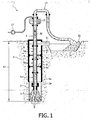
- figure 1 shows a schematic representation of a device according to the invention
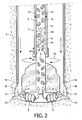
- figure 2 shows a schematic side view of a rotating drill head equipped with nozzles according to the invention.
- a device 1 for drilling a shaft 2 in a ground layer 3.
- Ground layer 3 preferably comprises rock, but may also comprise clay and/or related materials.
- Device 1 comprises a borehole casing 4 which can be arranged in ground 3 in known manner by means which are not shown.
- the diameter of borehole casing 4 is in principle all but unlimited, though preferably amounts to at least 1 m, more preferably at least 2 m, still more preferably at least 4 m and most preferably at least 6 m.
- Arranging borehole casing 4 in ground 3 can for instance take place by means of driving and/or drilling. Because borehole casing 4 supports on its underside 4a on a ground layer 3a, a substantially water-impermeable sealing is achieved.
- Borehole casing 4 generally comprises a thick-walled steel tube which is suitable for placing a drilling installation on the top side thereof and which remains substantially stationary during the drilling.
- Drill string 5 comprises a number of borehole casings 5a mutually connected by means of flanges. Hollow borehole casings 5a together form a central cavity 6.
- Drill string 5 is provided on the underside with a drill head 7 with cutting tools 8, for instance in the form of cutting discs.
- drill string 5 can if desired be provided with weighting collars (not shown), although this is not essential.
- drill string 5 is preferably provided with a number of stabilizers 9 which are arranged distributed in axial direction and which support against inner wall 4b of borehole casing 4.
- Device 1 also comprises means for maintaining a water column 10 in borehole casing 4, for instance in the form of a pump (not shown) with sufficient rise height and flow rate (typically for instance 1000 m3/h) so as to maintain the highest possible water level 11 in borehole casing 4.
- Device 1 further comprises means for setting drill string 5 into rotation in borehole casing 4.
- Such means preferably comprise a transmission in the form of a swivel 15 provided with a drive (not separately shown).
- the drill head is also set into rotation in drilling direction 20 (see figure 2 ), whereby ground 3 is crushed by the action of cutting tools 8.
- borehole casing 4 and drill string 5 run practically vertically in the shown figures, they can be adjusted to any angle relative to the ground surface, this from a jack-up platform or pontoon or from the shore when the device forms part of for instance a vehicle.
- a water column 10 is arranged in the space between the substantially coaxially disposed borehole casing 4 and drill string 5.
- This water column 10 provides for a pressure difference 12 between the upper side of drill string 5 at the position of water level 11 and the underside of drill string 5 at the position of cutting tools 8, wherein the pressure is of course higher on the underside. Owing to this pressure difference 12 and because borehole casing 5 is open on the underside, so that a throughfeed is possible to cavity 6, water and loosened ground material 31 flow in the direction indicated by arrows 22 and 23 into cavity 6.
- the shown preferred variant also comprises means for injecting air under a second pressure into the hollow drill string 5 at the position of drill head 7.
- These means comprise feed lines 16 which are arranged on drill string 5 and which are connected at the one outer end to a compressor 17 and which debouch at the other outer end into cavity 6 of drill string 5 via air inlet valves 18 (see also figure 2 ).
- Compressor 17 ensures that air is carried under a certain pressure through lines 16 in the direction indicated by arrows 19 and enters flow 30 (indicated by arrows 40).
- the second pressure produced by compressor 17 preferably lies between 2 and 50 bar, more preferably between 4 and 30 bar, and most preferably between 6 and 20 bar.
- Device 1 is further provided with one or more nozzles 25 (see figure 2 ) for injecting a first fluid, preferably water, under a first pressure into ground layers 3 at the position of drill head 7.
- Drill string 5 and/or borehole casing 4 and/or drill head 7 are provided with conduits (not shown) for feeding the first fluid to the nozzles.
- the conduits are connected to pressure means such as a pump or compressor for bringing the first fluid under pressure.
- the nozzles are preferably mounted on drill head 7 so that they co-rotate with the drill head, although mounting on for instance drill string 5 and/or on borehole casing 5a is likewise possible.
- Nozzles 25 are suitable for injecting the water under a first pressure of at least 200 bar, preferably at least 350 bar, more preferably at least 500 bar and most preferably at least 650 bar.
- the nozzles are directed substantially radially outward, whereby water jets 26 are injected into ground layer 3 at a greater depth than the lower outer end 4a of borehole casing 4.
- Extra ground material 3b is hereby removed or at least weakened at the position of underside 4a of borehole casing 4, whereby borehole casing 4 can move deeper into the ground 3.
- An underreamer construction is hereby no longer necessary.
- An additional advantage of injecting water under high pressure is that additional material (such as ground material 3b) is hereby loosened, whereby more loosened ground material reaches cavity 6 in the direction of arrows 22 and 23, and the drilling efficiency is increased.
- the transmission is designed such that it can transfer a first fluid flow under high pressure from the stationary to the rotating part of the device.
- Transmission 5 is therefore preferably suitable for withstanding an internal pressure of at least 200 bar, more preferably at least 350 bar, still more preferably at least 500 bar and most -preferably at least 650 bar, and is preferably leak-proof at such pressures.
- Swived 15 is further suitable for transmitting the necessary torque from the stationary to the rotating part of the device in order to transmit the second pressure to conduits 19, as well as for discharging the water - ground material mixture (30, 31).
- Swivel 15 is further suitable for retaining these properties under the influence of the vibrations which inevitably occur during the drilling, and which only increase as drill head 7 penetrates further into ground layers 3.
- the placing and orientation of nozzles 25 can be chosen as a function of the type of ground. It is therefore advantageous to mount nozzles 25 releasably on drill head 7 and/or drill string 5 so that they can be easily displaced. It is also advantageous to mount nozzles 25 movably, for instance pivotally, on drill head 7 and/or drill string 5, so that the fluid jets can be aimed in simple manner. It is further advantageous to place nozzles 25 such that they can approach relatively closely the ground layers for cutting. The cutting efficiency of nozzles decreases quickly under water, and is generally already negligible after several decimetres.
- the device according to the invention preferably further comprises means which make it possible to choose which nozzles must be activated at which moment, this subject to the properties of the ground layer for drilling.
- the feed lines for the first and second fluid can be long, particularly in the case of drilling at great depth. These lines are preferably carried substantially without bends from the upper side of device 1 to the lower part of drill string 5 (and/or drill head 7). Pressure losses are hereby prevented as far as possible.
- the invented device and method are particularly suitable for drilling shafts of relatively large diameters in composite grounds so as to enable forming and/or arranging of foundation piles therein.
- the device and method provide a new method of (hydraulic) underreaming.
- Arranging nozzles on the underside of the drill head ensures that cutting tools are less likely to become stuck fast in the ground layers.
- Arranging nozzles on the side of the drill head ensures that the diameter of the borehole under the borehole casing is increased, so that use of a vulnerable underreamer is no longer necessary.
Landscapes
- Engineering & Computer Science (AREA)
- Life Sciences & Earth Sciences (AREA)
- Geology (AREA)
- Mining & Mineral Resources (AREA)
- Physics & Mathematics (AREA)
- Environmental & Geological Engineering (AREA)
- Fluid Mechanics (AREA)
- General Life Sciences & Earth Sciences (AREA)
- Geochemistry & Mineralogy (AREA)
- Mechanical Engineering (AREA)
- Earth Drilling (AREA)
Priority Applications (1)
| Application Number | Priority Date | Filing Date | Title |
|---|---|---|---|
| PL10708787T PL2408992T3 (pl) | 2009-03-19 | 2010-03-18 | Sposób oraz urządzenie do szybów wiertniczych w warstwach gruntu składającego się ze skały, gliny i/lub podobnych materiałów |
Applications Claiming Priority (2)
| Application Number | Priority Date | Filing Date | Title |
|---|---|---|---|
| BE2009/0177A BE1018567A4 (nl) | 2009-03-19 | 2009-03-19 | Werkwijze en inrichting voor het boren van schachten in uit rots, klei en/of aanverwante materialen bestaande grondlagen. |
| PCT/EP2010/053514 WO2010106124A2 (en) | 2009-03-19 | 2010-03-18 | Method and device for drilling shafts in ground layers consisting of rock, clay and/or related materials |
Publications (2)
| Publication Number | Publication Date |
|---|---|
| EP2408992A2 EP2408992A2 (en) | 2012-01-25 |
| EP2408992B1 true EP2408992B1 (en) | 2015-10-21 |
Family
ID=41228315
Family Applications (1)
| Application Number | Title | Priority Date | Filing Date |
|---|---|---|---|
| EP10708787.6A Active EP2408992B1 (en) | 2009-03-19 | 2010-03-18 | Method and device for drilling shafts in ground layers consisting of rock, clay and/or related materials |
Country Status (8)
| Country | Link |
|---|---|
| US (1) | US9080389B2 (pl) |
| EP (1) | EP2408992B1 (pl) |
| AU (1) | AU2010224821B2 (pl) |
| BE (1) | BE1018567A4 (pl) |
| CA (1) | CA2755764C (pl) |
| DK (1) | DK2408992T3 (pl) |
| PL (1) | PL2408992T3 (pl) |
| WO (1) | WO2010106124A2 (pl) |
Families Citing this family (10)
| Publication number | Priority date | Publication date | Assignee | Title |
|---|---|---|---|---|
| BE1020365A4 (nl) * | 2012-01-02 | 2013-08-06 | Geosea N V | Inrichting en werkwijze voor het boren van schachten in een uit rots, klei en/of aanverwante materialen bestaande ondergrond. |
| KR101396911B1 (ko) | 2012-06-11 | 2014-05-19 | (주)부마씨이 | 연속굴반기의 에어챔버 분리형 드릴비트 조립체 및 이를 구비한 연속굴반기 |
| CN102900357B (zh) * | 2012-09-27 | 2016-01-20 | 三一重工股份有限公司 | 卤水采集方法 |
| MY189199A (en) | 2013-02-07 | 2022-01-31 | Dyno Nobel Inc | Systems for delivering explosives and methods related thereto |
| DK2999540T3 (en) * | 2013-05-20 | 2018-07-30 | Jtg And Partners Pty Ltd | A GRINDING APPLIANCE |
| CN103510866A (zh) * | 2013-09-10 | 2014-01-15 | 安徽三山机械制造有限公司 | 一种双出气通道的牙轮钻机 |
| CN104018786A (zh) * | 2014-05-12 | 2014-09-03 | 成都科创佳思科技有限公司 | 一种建筑用钻杆 |
| KR101652352B1 (ko) * | 2014-09-24 | 2016-09-01 | 삼성중공업 주식회사 | 굴삭 펌프 장치 |
| CN108086930B (zh) * | 2018-01-29 | 2024-03-26 | 吉林大学 | 松软岩土地层反循环跟管钻具及钻进工艺 |
| CN110984862A (zh) * | 2019-12-30 | 2020-04-10 | 通号建设集团有限公司 | 一种富厚砂层地质静压桩引孔装置及施工方法 |
Citations (2)
| Publication number | Priority date | Publication date | Assignee | Title |
|---|---|---|---|---|
| US2720381A (en) * | 1949-05-02 | 1955-10-11 | Thomas E Quick | Method and apparatus for hydraulic reaming of oil wells |
| WO1995033119A1 (en) * | 1994-05-27 | 1995-12-07 | Eric Clifford Braumann | Drilling apparatus |
Family Cites Families (7)
| Publication number | Priority date | Publication date | Assignee | Title |
|---|---|---|---|---|
| DE124203C (pl) * | ||||
| US3454119A (en) * | 1967-03-16 | 1969-07-08 | John Mcclinton | Jet-type reamer for use with drill pipe strings |
| US3674100A (en) * | 1970-08-12 | 1972-07-04 | Norman D Becker | Method and apparatus for drilling and casing a large diameter borehole |
| US4534426A (en) * | 1983-08-24 | 1985-08-13 | Unique Oil Tools, Inc. | Packer weighted and pressure differential method and apparatus for Big Hole drilling |
| US5212891A (en) * | 1991-01-25 | 1993-05-25 | The Charles Machine Works, Inc. | Soft excavator |
| DE4138356A1 (de) * | 1991-11-21 | 1993-05-27 | Gu Tiefbau Ag | Bohrvorrichtung fuer den tiefbau sowie verfahren zum herstellen von stabilisierenden saeulen oder aehnlichen gebilden in erdreich |
| US5586609A (en) * | 1994-12-15 | 1996-12-24 | Telejet Technologies, Inc. | Method and apparatus for drilling with high-pressure, reduced solid content liquid |
-
2009
- 2009-03-19 BE BE2009/0177A patent/BE1018567A4/nl not_active IP Right Cessation
-
2010
- 2010-03-18 PL PL10708787T patent/PL2408992T3/pl unknown
- 2010-03-18 CA CA2755764A patent/CA2755764C/en active Active
- 2010-03-18 EP EP10708787.6A patent/EP2408992B1/en active Active
- 2010-03-18 AU AU2010224821A patent/AU2010224821B2/en active Active
- 2010-03-18 DK DK10708787.6T patent/DK2408992T3/en active
- 2010-03-18 WO PCT/EP2010/053514 patent/WO2010106124A2/en not_active Ceased
- 2010-03-18 US US13/257,256 patent/US9080389B2/en active Active
Patent Citations (2)
| Publication number | Priority date | Publication date | Assignee | Title |
|---|---|---|---|---|
| US2720381A (en) * | 1949-05-02 | 1955-10-11 | Thomas E Quick | Method and apparatus for hydraulic reaming of oil wells |
| WO1995033119A1 (en) * | 1994-05-27 | 1995-12-07 | Eric Clifford Braumann | Drilling apparatus |
Also Published As
| Publication number | Publication date |
|---|---|
| AU2010224821A1 (en) | 2011-10-27 |
| BE1018567A4 (nl) | 2011-03-01 |
| CA2755764C (en) | 2017-11-21 |
| EP2408992A2 (en) | 2012-01-25 |
| WO2010106124A2 (en) | 2010-09-23 |
| PL2408992T3 (pl) | 2016-06-30 |
| AU2010224821B2 (en) | 2015-11-19 |
| US20120118644A1 (en) | 2012-05-17 |
| CA2755764A1 (en) | 2010-09-23 |
| WO2010106124A3 (en) | 2011-03-24 |
| DK2408992T3 (en) | 2016-02-01 |
| US9080389B2 (en) | 2015-07-14 |
Similar Documents
| Publication | Publication Date | Title |
|---|---|---|
| EP2408992B1 (en) | Method and device for drilling shafts in ground layers consisting of rock, clay and/or related materials | |
| CN110566114B (zh) | 旋挖集束式潜孔锤的硬岩钻进成桩施工方法 | |
| US8757289B2 (en) | Underwater drilling arrangement and method for making a bore in a bed of a water body | |
| US3965687A (en) | Apparatus for anchoring a structure to the floor of a body of water | |
| EP2615239B1 (en) | Device and method for drilling shafts in a ground consisting of rock, clay and/or related materials | |
| JP5049913B2 (ja) | 削孔機 | |
| KR101868086B1 (ko) | 천공 및 그라우팅 로드장치 | |
| CA2617432A1 (en) | Method and device for producing a cased string bore | |
| EP4416366B1 (en) | A detachable fluidisation device | |
| EP1600560B1 (en) | A method and device for forming a pile | |
| JP3940764B2 (ja) | ドレーンパイプ工法および地盤穿孔装置 | |
| JP4115091B2 (ja) | 回転圧入鋼管杭の施工方法 | |
| EP3252263B1 (en) | Device and method for drilling a large diameter borehole | |
| KR100880365B1 (ko) | 산업시설용 수중구조물의 수중설치를 위한 확공굴착용굴착장치 | |
| CN115748792B (zh) | 一种带减阻系统的桶型基础及铰吸式沉贯安装方法 | |
| WO2008072950A2 (en) | Foundation system for the forming of a foundation pile in the ground | |
| CN101196005A (zh) | 钻吸桩结构及其施工方法 | |
| KR101546231B1 (ko) | 자천공 해상친환경 말뚝 시공 방법 | |
| EP3260650B1 (en) | Device and method for drilling a shaft in a substrate | |
| CN112878900A (zh) | 一种穿越碎石地层的钻进工具 | |
| WO2023218396A1 (en) | Method of installation of a drill pile and the drill pill | |
| JP2005097853A (ja) | 上下可動式回転テーブルを備えた掘削装置と二重管方式による鋼管杭の施工法ならびに基礎杭構築のための掘進方法 | |
| Nakayama | Large diameter drilling operations of multi head down the hole hammer drill through boulders and granite | |
| KR20190031822A (ko) | 교각기초 구축을 위한 수중 지반 굴착장치 | |
| JPH11229739A (ja) | 加圧水による斜杭削孔工法および加圧水供給装置 |
Legal Events
| Date | Code | Title | Description |
|---|---|---|---|
| PUAI | Public reference made under article 153(3) epc to a published international application that has entered the european phase |
Free format text: ORIGINAL CODE: 0009012 |
|
| 17P | Request for examination filed |
Effective date: 20111019 |
|
| AK | Designated contracting states |
Kind code of ref document: A2 Designated state(s): AT BE BG CH CY CZ DE DK EE ES FI FR GB GR HR HU IE IS IT LI LT LU LV MC MK MT NL NO PL PT RO SE SI SK SM TR |
|
| DAX | Request for extension of the european patent (deleted) | ||
| 17Q | First examination report despatched |
Effective date: 20131021 |
|
| GRAP | Despatch of communication of intention to grant a patent |
Free format text: ORIGINAL CODE: EPIDOSNIGR1 |
|
| INTG | Intention to grant announced |
Effective date: 20150616 |
|
| GRAS | Grant fee paid |
Free format text: ORIGINAL CODE: EPIDOSNIGR3 |
|
| GRAA | (expected) grant |
Free format text: ORIGINAL CODE: 0009210 |
|
| AK | Designated contracting states |
Kind code of ref document: B1 Designated state(s): AT BE BG CH CY CZ DE DK EE ES FI FR GB GR HR HU IE IS IT LI LT LU LV MC MK MT NL NO PL PT RO SE SI SK SM TR |
|
| REG | Reference to a national code |
Ref country code: GB Ref legal event code: FG4D |
|
| REG | Reference to a national code |
Ref country code: CH Ref legal event code: EP |
|
| REG | Reference to a national code |
Ref country code: AT Ref legal event code: REF Ref document number: 756737 Country of ref document: AT Kind code of ref document: T Effective date: 20151115 |
|
| REG | Reference to a national code |
Ref country code: IE Ref legal event code: FG4D |
|
| REG | Reference to a national code |
Ref country code: DE Ref legal event code: R096 Ref document number: 602010028371 Country of ref document: DE |
|
| REG | Reference to a national code |
Ref country code: DK Ref legal event code: T3 Effective date: 20160126 |
|
| REG | Reference to a national code |
Ref country code: LT Ref legal event code: MG4D |
|
| REG | Reference to a national code |
Ref country code: NL Ref legal event code: FP |
|
| REG | Reference to a national code |
Ref country code: AT Ref legal event code: MK05 Ref document number: 756737 Country of ref document: AT Kind code of ref document: T Effective date: 20151021 |
|
| REG | Reference to a national code |
Ref country code: FR Ref legal event code: PLFP Year of fee payment: 7 |
|
| PG25 | Lapsed in a contracting state [announced via postgrant information from national office to epo] |
Ref country code: IS Free format text: LAPSE BECAUSE OF FAILURE TO SUBMIT A TRANSLATION OF THE DESCRIPTION OR TO PAY THE FEE WITHIN THE PRESCRIBED TIME-LIMIT Effective date: 20160221 Ref country code: IT Free format text: LAPSE BECAUSE OF FAILURE TO SUBMIT A TRANSLATION OF THE DESCRIPTION OR TO PAY THE FEE WITHIN THE PRESCRIBED TIME-LIMIT Effective date: 20151021 Ref country code: NO Free format text: LAPSE BECAUSE OF FAILURE TO SUBMIT A TRANSLATION OF THE DESCRIPTION OR TO PAY THE FEE WITHIN THE PRESCRIBED TIME-LIMIT Effective date: 20160121 Ref country code: ES Free format text: LAPSE BECAUSE OF FAILURE TO SUBMIT A TRANSLATION OF THE DESCRIPTION OR TO PAY THE FEE WITHIN THE PRESCRIBED TIME-LIMIT Effective date: 20151021 Ref country code: HR Free format text: LAPSE BECAUSE OF FAILURE TO SUBMIT A TRANSLATION OF THE DESCRIPTION OR TO PAY THE FEE WITHIN THE PRESCRIBED TIME-LIMIT Effective date: 20151021 Ref country code: LT Free format text: LAPSE BECAUSE OF FAILURE TO SUBMIT A TRANSLATION OF THE DESCRIPTION OR TO PAY THE FEE WITHIN THE PRESCRIBED TIME-LIMIT Effective date: 20151021 |
|
| PG25 | Lapsed in a contracting state [announced via postgrant information from national office to epo] |
Ref country code: GR Free format text: LAPSE BECAUSE OF FAILURE TO SUBMIT A TRANSLATION OF THE DESCRIPTION OR TO PAY THE FEE WITHIN THE PRESCRIBED TIME-LIMIT Effective date: 20160122 Ref country code: PT Free format text: LAPSE BECAUSE OF FAILURE TO SUBMIT A TRANSLATION OF THE DESCRIPTION OR TO PAY THE FEE WITHIN THE PRESCRIBED TIME-LIMIT Effective date: 20160222 Ref country code: SE Free format text: LAPSE BECAUSE OF FAILURE TO SUBMIT A TRANSLATION OF THE DESCRIPTION OR TO PAY THE FEE WITHIN THE PRESCRIBED TIME-LIMIT Effective date: 20151021 Ref country code: FI Free format text: LAPSE BECAUSE OF FAILURE TO SUBMIT A TRANSLATION OF THE DESCRIPTION OR TO PAY THE FEE WITHIN THE PRESCRIBED TIME-LIMIT Effective date: 20151021 Ref country code: AT Free format text: LAPSE BECAUSE OF FAILURE TO SUBMIT A TRANSLATION OF THE DESCRIPTION OR TO PAY THE FEE WITHIN THE PRESCRIBED TIME-LIMIT Effective date: 20151021 Ref country code: LV Free format text: LAPSE BECAUSE OF FAILURE TO SUBMIT A TRANSLATION OF THE DESCRIPTION OR TO PAY THE FEE WITHIN THE PRESCRIBED TIME-LIMIT Effective date: 20151021 |
|
| REG | Reference to a national code |
Ref country code: DE Ref legal event code: R097 Ref document number: 602010028371 Country of ref document: DE |
|
| PG25 | Lapsed in a contracting state [announced via postgrant information from national office to epo] |
Ref country code: CZ Free format text: LAPSE BECAUSE OF FAILURE TO SUBMIT A TRANSLATION OF THE DESCRIPTION OR TO PAY THE FEE WITHIN THE PRESCRIBED TIME-LIMIT Effective date: 20151021 |
|
| PLBE | No opposition filed within time limit |
Free format text: ORIGINAL CODE: 0009261 |
|
| STAA | Information on the status of an ep patent application or granted ep patent |
Free format text: STATUS: NO OPPOSITION FILED WITHIN TIME LIMIT |
|
| PG25 | Lapsed in a contracting state [announced via postgrant information from national office to epo] |
Ref country code: SK Free format text: LAPSE BECAUSE OF FAILURE TO SUBMIT A TRANSLATION OF THE DESCRIPTION OR TO PAY THE FEE WITHIN THE PRESCRIBED TIME-LIMIT Effective date: 20151021 Ref country code: SM Free format text: LAPSE BECAUSE OF FAILURE TO SUBMIT A TRANSLATION OF THE DESCRIPTION OR TO PAY THE FEE WITHIN THE PRESCRIBED TIME-LIMIT Effective date: 20151021 Ref country code: RO Free format text: LAPSE BECAUSE OF FAILURE TO SUBMIT A TRANSLATION OF THE DESCRIPTION OR TO PAY THE FEE WITHIN THE PRESCRIBED TIME-LIMIT Effective date: 20151021 Ref country code: EE Free format text: LAPSE BECAUSE OF FAILURE TO SUBMIT A TRANSLATION OF THE DESCRIPTION OR TO PAY THE FEE WITHIN THE PRESCRIBED TIME-LIMIT Effective date: 20151021 |
|
| 26N | No opposition filed |
Effective date: 20160722 |
|
| PG25 | Lapsed in a contracting state [announced via postgrant information from national office to epo] |
Ref country code: MC Free format text: LAPSE BECAUSE OF FAILURE TO SUBMIT A TRANSLATION OF THE DESCRIPTION OR TO PAY THE FEE WITHIN THE PRESCRIBED TIME-LIMIT Effective date: 20151021 Ref country code: LU Free format text: LAPSE BECAUSE OF FAILURE TO SUBMIT A TRANSLATION OF THE DESCRIPTION OR TO PAY THE FEE WITHIN THE PRESCRIBED TIME-LIMIT Effective date: 20160318 |
|
| REG | Reference to a national code |
Ref country code: CH Ref legal event code: PL |
|
| PG25 | Lapsed in a contracting state [announced via postgrant information from national office to epo] |
Ref country code: SI Free format text: LAPSE BECAUSE OF FAILURE TO SUBMIT A TRANSLATION OF THE DESCRIPTION OR TO PAY THE FEE WITHIN THE PRESCRIBED TIME-LIMIT Effective date: 20151021 |
|
| REG | Reference to a national code |
Ref country code: IE Ref legal event code: MM4A |
|
| PG25 | Lapsed in a contracting state [announced via postgrant information from national office to epo] |
Ref country code: IE Free format text: LAPSE BECAUSE OF NON-PAYMENT OF DUE FEES Effective date: 20160318 Ref country code: LI Free format text: LAPSE BECAUSE OF NON-PAYMENT OF DUE FEES Effective date: 20160331 Ref country code: CH Free format text: LAPSE BECAUSE OF NON-PAYMENT OF DUE FEES Effective date: 20160331 |
|
| REG | Reference to a national code |
Ref country code: FR Ref legal event code: PLFP Year of fee payment: 8 |
|
| PG25 | Lapsed in a contracting state [announced via postgrant information from national office to epo] |
Ref country code: MT Free format text: LAPSE BECAUSE OF FAILURE TO SUBMIT A TRANSLATION OF THE DESCRIPTION OR TO PAY THE FEE WITHIN THE PRESCRIBED TIME-LIMIT Effective date: 20151021 |
|
| REG | Reference to a national code |
Ref country code: FR Ref legal event code: PLFP Year of fee payment: 9 |
|
| PG25 | Lapsed in a contracting state [announced via postgrant information from national office to epo] |
Ref country code: CY Free format text: LAPSE BECAUSE OF FAILURE TO SUBMIT A TRANSLATION OF THE DESCRIPTION OR TO PAY THE FEE WITHIN THE PRESCRIBED TIME-LIMIT Effective date: 20151021 Ref country code: HU Free format text: LAPSE BECAUSE OF FAILURE TO SUBMIT A TRANSLATION OF THE DESCRIPTION OR TO PAY THE FEE WITHIN THE PRESCRIBED TIME-LIMIT; INVALID AB INITIO Effective date: 20100318 |
|
| PG25 | Lapsed in a contracting state [announced via postgrant information from national office to epo] |
Ref country code: MT Free format text: LAPSE BECAUSE OF FAILURE TO SUBMIT A TRANSLATION OF THE DESCRIPTION OR TO PAY THE FEE WITHIN THE PRESCRIBED TIME-LIMIT Effective date: 20160331 Ref country code: MK Free format text: LAPSE BECAUSE OF FAILURE TO SUBMIT A TRANSLATION OF THE DESCRIPTION OR TO PAY THE FEE WITHIN THE PRESCRIBED TIME-LIMIT Effective date: 20151021 Ref country code: TR Free format text: LAPSE BECAUSE OF FAILURE TO SUBMIT A TRANSLATION OF THE DESCRIPTION OR TO PAY THE FEE WITHIN THE PRESCRIBED TIME-LIMIT Effective date: 20151021 |
|
| PG25 | Lapsed in a contracting state [announced via postgrant information from national office to epo] |
Ref country code: BG Free format text: LAPSE BECAUSE OF FAILURE TO SUBMIT A TRANSLATION OF THE DESCRIPTION OR TO PAY THE FEE WITHIN THE PRESCRIBED TIME-LIMIT Effective date: 20151021 |
|
| REG | Reference to a national code |
Ref country code: DE Ref legal event code: R082 Ref document number: 602010028371 Country of ref document: DE Representative=s name: ARNOLD & SIEDSMA, DE Ref country code: DE Ref legal event code: R081 Ref document number: 602010028371 Country of ref document: DE Owner name: DEME OFFSHORE BE NV, BE Free format text: FORMER OWNER: GEOSEA NV, ZWIJNDRECHT, BE |
|
| REG | Reference to a national code |
Ref country code: GB Ref legal event code: 732E Free format text: REGISTERED BETWEEN 20200305 AND 20200311 |
|
| REG | Reference to a national code |
Ref country code: NL Ref legal event code: HC Owner name: DEME OFFSHORE HOLDING N.V.; NL Free format text: DETAILS ASSIGNMENT: CHANGE OF OWNER(S), CHANGE OF OWNER(S) NAME; FORMER OWNER NAME: GEOSEA NV Effective date: 20200612 Ref country code: NL Ref legal event code: PD Owner name: DEME OFFSHORE BE N.V.; BE Free format text: DETAILS ASSIGNMENT: CHANGE OF OWNER(S), ASSIGNMENT; FORMER OWNER NAME: DEME OFFSHORE HOLDING N.V. Effective date: 20200612 |
|
| REG | Reference to a national code |
Ref country code: BE Ref legal event code: HC Owner name: DEME OFFSHORE HOLDING N.V.; BE Free format text: DETAILS ASSIGNMENT: CHANGE OF OWNER(S), CHANGEMENT DE NOM DU PROPRIETAIRE Effective date: 20200514 Ref country code: BE Ref legal event code: PD Owner name: DEME OFFSHORE BE N.V.; BE Free format text: DETAILS ASSIGNMENT: CHANGE OF OWNER(S), CESSION Effective date: 20200514 |
|
| P01 | Opt-out of the competence of the unified patent court (upc) registered |
Effective date: 20230526 |
|
| PGFP | Annual fee paid to national office [announced via postgrant information from national office to epo] |
Ref country code: BE Payment date: 20241210 Year of fee payment: 16 Ref country code: NL Payment date: 20241211 Year of fee payment: 16 |
|
| PGFP | Annual fee paid to national office [announced via postgrant information from national office to epo] |
Ref country code: FR Payment date: 20241219 Year of fee payment: 16 |
|
| PGFP | Annual fee paid to national office [announced via postgrant information from national office to epo] |
Ref country code: DE Payment date: 20241210 Year of fee payment: 16 |
|
| PGFP | Annual fee paid to national office [announced via postgrant information from national office to epo] |
Ref country code: GB Payment date: 20250214 Year of fee payment: 16 |
|
| PGFP | Annual fee paid to national office [announced via postgrant information from national office to epo] |
Ref country code: PL Payment date: 20250302 Year of fee payment: 16 |
|
| PGFP | Annual fee paid to national office [announced via postgrant information from national office to epo] |
Ref country code: DK Payment date: 20251223 Year of fee payment: 17 |