EP2408056A1 - Electrode assembly and rechargeable battery including the same - Google Patents
Electrode assembly and rechargeable battery including the same Download PDFInfo
- Publication number
- EP2408056A1 EP2408056A1 EP11173258A EP11173258A EP2408056A1 EP 2408056 A1 EP2408056 A1 EP 2408056A1 EP 11173258 A EP11173258 A EP 11173258A EP 11173258 A EP11173258 A EP 11173258A EP 2408056 A1 EP2408056 A1 EP 2408056A1
- Authority
- EP
- European Patent Office
- Prior art keywords
- tab
- electrode
- positive electrode
- width
- electrode assembly
- Prior art date
- Legal status (The legal status is an assumption and is not a legal conclusion. Google has not performed a legal analysis and makes no representation as to the accuracy of the status listed.)
- Granted
Links
Images



Classifications
-
- H—ELECTRICITY
- H01—ELECTRIC ELEMENTS
- H01M—PROCESSES OR MEANS, e.g. BATTERIES, FOR THE DIRECT CONVERSION OF CHEMICAL ENERGY INTO ELECTRICAL ENERGY
- H01M50/00—Constructional details or processes of manufacture of the non-active parts of electrochemical cells other than fuel cells, e.g. hybrid cells
- H01M50/50—Current conducting connections for cells or batteries
- H01M50/543—Terminals
-
- H—ELECTRICITY
- H01—ELECTRIC ELEMENTS
- H01M—PROCESSES OR MEANS, e.g. BATTERIES, FOR THE DIRECT CONVERSION OF CHEMICAL ENERGY INTO ELECTRICAL ENERGY
- H01M10/00—Secondary cells; Manufacture thereof
- H01M10/04—Construction or manufacture in general
- H01M10/0431—Cells with wound or folded electrodes
-
- H—ELECTRICITY
- H01—ELECTRIC ELEMENTS
- H01M—PROCESSES OR MEANS, e.g. BATTERIES, FOR THE DIRECT CONVERSION OF CHEMICAL ENERGY INTO ELECTRICAL ENERGY
- H01M50/00—Constructional details or processes of manufacture of the non-active parts of electrochemical cells other than fuel cells, e.g. hybrid cells
- H01M50/10—Primary casings; Jackets or wrappings
- H01M50/102—Primary casings; Jackets or wrappings characterised by their shape or physical structure
- H01M50/107—Primary casings; Jackets or wrappings characterised by their shape or physical structure having curved cross-section, e.g. round or elliptic
-
- H—ELECTRICITY
- H01—ELECTRIC ELEMENTS
- H01M—PROCESSES OR MEANS, e.g. BATTERIES, FOR THE DIRECT CONVERSION OF CHEMICAL ENERGY INTO ELECTRICAL ENERGY
- H01M50/00—Constructional details or processes of manufacture of the non-active parts of electrochemical cells other than fuel cells, e.g. hybrid cells
- H01M50/50—Current conducting connections for cells or batteries
-
- H—ELECTRICITY
- H01—ELECTRIC ELEMENTS
- H01M—PROCESSES OR MEANS, e.g. BATTERIES, FOR THE DIRECT CONVERSION OF CHEMICAL ENERGY INTO ELECTRICAL ENERGY
- H01M50/00—Constructional details or processes of manufacture of the non-active parts of electrochemical cells other than fuel cells, e.g. hybrid cells
- H01M50/50—Current conducting connections for cells or batteries
- H01M50/528—Fixed electrical connections, i.e. not intended for disconnection
-
- H—ELECTRICITY
- H01—ELECTRIC ELEMENTS
- H01M—PROCESSES OR MEANS, e.g. BATTERIES, FOR THE DIRECT CONVERSION OF CHEMICAL ENERGY INTO ELECTRICAL ENERGY
- H01M50/00—Constructional details or processes of manufacture of the non-active parts of electrochemical cells other than fuel cells, e.g. hybrid cells
- H01M50/50—Current conducting connections for cells or batteries
- H01M50/531—Electrode connections inside a battery casing
- H01M50/534—Electrode connections inside a battery casing characterised by the material of the leads or tabs
-
- H—ELECTRICITY
- H01—ELECTRIC ELEMENTS
- H01M—PROCESSES OR MEANS, e.g. BATTERIES, FOR THE DIRECT CONVERSION OF CHEMICAL ENERGY INTO ELECTRICAL ENERGY
- H01M50/00—Constructional details or processes of manufacture of the non-active parts of electrochemical cells other than fuel cells, e.g. hybrid cells
- H01M50/50—Current conducting connections for cells or batteries
- H01M50/531—Electrode connections inside a battery casing
- H01M50/538—Connection of several leads or tabs of wound or folded electrode stacks
-
- H—ELECTRICITY
- H01—ELECTRIC ELEMENTS
- H01M—PROCESSES OR MEANS, e.g. BATTERIES, FOR THE DIRECT CONVERSION OF CHEMICAL ENERGY INTO ELECTRICAL ENERGY
- H01M50/00—Constructional details or processes of manufacture of the non-active parts of electrochemical cells other than fuel cells, e.g. hybrid cells
- H01M50/50—Current conducting connections for cells or batteries
- H01M50/543—Terminals
- H01M50/552—Terminals characterised by their shape
- H01M50/559—Terminals adapted for cells having curved cross-section, e.g. round, elliptic or button cells
- H01M50/56—Cup shaped terminals
-
- Y—GENERAL TAGGING OF NEW TECHNOLOGICAL DEVELOPMENTS; GENERAL TAGGING OF CROSS-SECTIONAL TECHNOLOGIES SPANNING OVER SEVERAL SECTIONS OF THE IPC; TECHNICAL SUBJECTS COVERED BY FORMER USPC CROSS-REFERENCE ART COLLECTIONS [XRACs] AND DIGESTS
- Y02—TECHNOLOGIES OR APPLICATIONS FOR MITIGATION OR ADAPTATION AGAINST CLIMATE CHANGE
- Y02E—REDUCTION OF GREENHOUSE GAS [GHG] EMISSIONS, RELATED TO ENERGY GENERATION, TRANSMISSION OR DISTRIBUTION
- Y02E60/00—Enabling technologies; Technologies with a potential or indirect contribution to GHG emissions mitigation
- Y02E60/10—Energy storage using batteries
-
- Y—GENERAL TAGGING OF NEW TECHNOLOGICAL DEVELOPMENTS; GENERAL TAGGING OF CROSS-SECTIONAL TECHNOLOGIES SPANNING OVER SEVERAL SECTIONS OF THE IPC; TECHNICAL SUBJECTS COVERED BY FORMER USPC CROSS-REFERENCE ART COLLECTIONS [XRACs] AND DIGESTS
- Y02—TECHNOLOGIES OR APPLICATIONS FOR MITIGATION OR ADAPTATION AGAINST CLIMATE CHANGE
- Y02P—CLIMATE CHANGE MITIGATION TECHNOLOGIES IN THE PRODUCTION OR PROCESSING OF GOODS
- Y02P70/00—Climate change mitigation technologies in the production process for final industrial or consumer products
- Y02P70/50—Manufacturing or production processes characterised by the final manufactured product
Definitions
- Embodiments relate to an electrode assembly and a rechargeable battery including the same.
- Rechargeable batteries may be charged and discharged, unlike primary batteries that cannot be charged.
- Small capacity rechargeable batteries maybe used for small portable electronic devices e.g., mobile phones, laptop computers, and camcorders.
- Large capacity batteries may be used as power sources for, e.g., driving motors of hybrid vehicles, etc.
- the rechargeable battery may include an electrode assembly made of a positive electrode, a negative electrode, and a separator interposed therebetween.
- the electrode assembly may have a stacked structure in which the positive electrode, the separator, and the negative electrode are sequentially deposited, or a jelly-roll structure in which the positive electrode, the separator, and the negative electrode are spiral-wound, according to the use and the object thereof.
- the electrode assembly of the jelly-roll structure may be accommodated in a case of, e.g., a cylindrical type, a prismatic type, a pouch type, etc.
- a cross-section of the electrode assembly of the jelly-roll structure may be, e.g., circular or oval, and may include electrode tabs respectively coupled to the positive electrode and the negative electrode.
- a multi-tab including a plurality of electrode tabs may be used, as the demand for high power rechargeable batteries has recently increased.
- Embodiments are directed to an electrode assembly and a rechargeable battery including the same.
- an electrode assembly including a first electrode, a second electrode, and a separator interposed therebetween, wherein the first electrode, the second electrode, and the separator are spiral-wound in a jelly-roll structure, the first electrode includes at least two first uncoated regions separated from each other and a first tab coupled to one of the first uncoated regions and a second tab coupled to another of the first uncoated regions, the first tab and the second tab protruding from one side of the jelly-roll structure, the first tab is disposed near a center of the jelly-roll structure and the second tab is disposed near an outer circumference of the jelly-roll structure, and a width of the first tab is smaller than a width of the second tab. That is, the first tab is disposed at a center position of the jelly-roll structure and the second tab is disposed relatively closer to an outer circumference of the jelly-roll structure.
- the first electrode may have a band shape, and the two first uncoated regions may be disposed on end edges of the first electrode.
- the first electrode may have a band shape, and the one of the first uncoated regions may be on a center portion of the first electrode and the other of the first uncoated regions may be on an end edge of the first electrode.
- the width of the first tab equals 2 ⁇ r x 0,05...0,08. That is, the width of the first tab may equal 2 ⁇ r x 0,06...0,07; in particular 2 ⁇ r x 0,065, r being a radius of the bottom surface of the elly-roll structure.
- the width of the first tab may be about 2,8 mm to about 7 mm.
- width of the first tab may be 2,8 mm to 7 mm.
- the width of the second tab may equal 2 ⁇ r x 0,055...0,085. That is, the width of the second tab may equal 2 ⁇ r x 0,065...0,075, in particular the width of the second tab may equal 2 ⁇ r x 0,07; r being a radius of the bottom surface of the jelly-roll structure.
- the width of the second tab may be about 5.1 mm to about 11 mm.
- the width of the second tab may be 5,1 mm to 11 mm.
- a thickness of the first tab may be smaller than a thickness of the second tab.
- the thickness of the first tab may be about 0,05 mm to about 0,15 mm.
- the thickness of the first tab may be 0,05 mm to 0,15 mm
- the thickness of the second tab may be about 0,1 mm to about 0,2 mm.
- the thickness of the second tab may be 0,1 mm to 0,2 mm.
- the first electrode may be a positive electrode.
- the second electrode may include at least two second uncoated regions and a third tab on one of the second uncoated regions and a fourth tab on another of the second uncoated regions, the third tab and the fourth tab protruding to a side opposite to the one side from which the first tab and the second tab protrude, the third tab may be disposed near a center of the jelly-roll structure and the fourth tab may be disposed near an outer circumference of the jelly-roll structure, and a width of the third tab may be smaller than a width of the fourth tab. That is, the third tab is disposed at a center position of the jelly-roll structure and the fourth tab is disposed relatively closer to an outer circumference of the jelly-roll structure.
- the width of the third tab equals 2 ⁇ r x 0,05...0,08. That is, the width of the third tab may equal 2 ⁇ r x 0,06...0,07, in particular 2 ⁇ r x 0,065, r being a radius of the bottom surface of the elly-roll structure.
- the width of the fourth tab may equal 2 ⁇ r x 0,055...0,085; preferably 2 ⁇ r x 0,065...0,075; in particular 2 ⁇ r x 0,07, r being a radius of the bottom surface of the jelly-roll structure.
- a rechargeable battery including an electrode assembly, the electrode assembly including a first electrode, a second electrode, and a separator interposed therebetween; a case for receiving the electrode assembly, and a cap assembly coupled with the case and electrically connected to the electrode assembly, wherein the first electrode, the second electrode, and the separator are spiral-wound in a jelly-roll structure having a cylindrical shape, the first electrode includes at least two first uncoated regions separated from each other and a first tab coupled to one of the first uncoated regions and a second tab coupled to another of the first uncoated regions, the first tab and the second tab protruding from one side of the elly-roll structure, the first tab is disposed near a center of the elly-roll structure and the second tab is disposed near an outer circumference of the jelly-roll structure, and a width of the first tab is smaller than a width of the second tab.
- the width of the first tab may equal 2 ⁇ r x 0,065
- the width of the second tab may equal 2 ⁇ r x 0,07
- r may be a radius of a bottom surface of the jelly-roll structure.
- the width of the first tab may be about 2.8 mm to about 7 mm, and the width of the second tab may be about 5.1 mm to about 11 mm.
- a thickness of the first tab may be smaller than a thickness of the second tab.
- the second electrode may include at least two second uncoated regions and a third tab on one of the second uncoated regions and a fourth tab on another of the second uncoated regions, the third tab and the fourth tab protruding to a side opposite to the one side from which the first tab and the second tab protrude, and the third tab may be disposed near a center of the jelly-roll structure and the fourth tab may be disposed near an outer circumference of the jelly-roll structure, and a width of the third tab may be smaller than a width of the fourth tab.
- the width of the third tab may equal 2 ⁇ r x 0,065, the width of the fourth tab may equal 2 ⁇ r x 0,07, and r may be a radius of a bottom surface of the jelly-roll structure.
- a thickness of the third tab may be smaller than a thickness of the fourth tab.
- FIG. 1 illustrates a cut-away perspective view of a rechargeable battery according to an embodiment
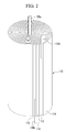
- FIG. 2 illustrates a perspective view of an electrode assembly of FIG. 1 ;
- FIG. 3 illustrates a schematic view showing an arrangement of a positive electrode tab of the electrode assembly of FIG. 2 ;
- FIG. 4 illustrates a schematic perspective view of the electrode assembly of FIG. 2 .
- FIG. 5 illustrates a schematic view of an electrode assembly according to another embodiment
- FIG. 1 illustrates a cut-away perspective view of a rechargeable battery according to an embodiment.
- a rechargeable battery 100 may include an electrode assembly 110 for generating a current, a case 120 for receiving the electrode assembly 110, and a cap assembly 140 coupled to the case 120 and being electrically connected to the electrode assembly 110.
- the electrode assembly 110 may include a first electrode 112, a second electrode 113, and a separator 114 interposed therebetween.
- the first electrode 112 may be a positive electrode and the second electrode 113 may be a negative electrode, however a polarity of the first electrode and the second electrode may be reversed.
- the positive electrode 112, the negative electrode 113, and the separator 114 may be connected in one direction thereby forming a band shape.
- the electrode assembly 110 may be formed in a jelly-roll structure in which the positive electrode 112, the negative electrode 113, and the separator 114 are continuously deposited and spiral-wound. In an implementation, a longitudinal cross section of the jelly-roll structure may be round.
- the positive electrode 112 may include a coating portion in which a positive electrode active material is coated on a current collector made of, e.g., aluminum.
- the positive electrode 112 may include a positive electrode uncoated region 112a where the active material is not coated.
- the negative electrode 113 may include a coating portion in which a negative electrode active material is coated on a current collector made of, e.g., copper or aluminum.
- the negative electrode 113 may include a negative electrode uncoated region 113a where the active material is not coated.
- a first positive electrode tab 135a and a second positive electrode tab 135b may be formed in or coupled to the positive electrode uncoated region 112a.
- a first negative electrode tab 136a and a second negative electrode tab 136b may be formed in or coupled to the negative electrode uncoated region 113a.
- the case 120 may have a cylindrical shape with one side thereof open to facilitation insertion of the electrode assembly 110 therethrough.
- the case 120 may be made of a conductive metal, e.g., aluminum, an aluminum alloy, or nickel-plated steel.
- the case 120 may be connected to the negative electrode tabs 136a and 136b, thereby functioning as a negative electrode terminal of the rechargeable battery 100.
- the cap assembly 140 may be fixed through, e.g., clamping, after fitting the same in the opened side of the case 120. In this process, a beading portion 123 and a clamping portion 125 may be formed along a circumference of an upper portion of the case 120.
- the cap assembly 140 may include a cap plate 143, a vent plate 160, a gasket 144, and a safety plate 141.
- the cap plate 143 may include a protrusion 143a protruding upwardly and an exhaust port 143b penetrating inside the case 120. Also, a notch 161 may be formed in the vent plate 160 under the cap plate 143. The notch 161 may be fractured when a pressure inside the case 120 exceeds a predetermined pressure, thereby suppressing an explosion caused an excess increase of the inner pressure of the rechargeable battery 100.
- the vent plate 160 may be electrically connected to the positive electrode 112 through the positive electrode tabs 135a and 135b.
- the positive electrode tabs 135a and 135b may be directly connected to the vent plate 160, however the embodiments are not limited thereto; and the vent plate 160 may include a middle member (not illustrated) and may be connected to the positive electrode tab 135a and 135b through the middle member.
- the safety plate 141 may be disposed between the cap plate 143 and the vent plate 160 and may include a positive temperature coefficient element.
- the positive temperature coefficient element may be an element whose electrical resistance may be quickly increased if a temperature of the element exceeds a predetermined temperature, thereby interrupting a flow of a charge or discharge current when a temperature of the rechargeable battery 100 reaches or exceeds a predetermined temperature.
- the gasket 144 may enclose or surround a circumference of the cap plate 143, the vent plate 160, and the safety plate 141.
- the gasket 144 may be made of an insulating material, thereby insulating the cap assembly 140 from the case 120.
- the cap assembly 140 and the circumferential structure is merely an exemplary structure, and the embodiments are not limited to this structure.
- FIG. 2 illustrates a perspective view of an electrode assembly of FIG. 1 .
- FIG. 3 illustrates a schematic view showing an arrangement of a positive electrode tab of the electrode assembly of FIG. 2 .
- the electrode assembly 110 according to the present embodiment will be described with reference to these drawings.
- the electrode assembly 110 may have the jelly-roll structure in which the separator 114, the positive electrode 112, the separator 114, and the negative electrode 113 are sequentially deposited and spiral-wound.
- the electrode assembly 110 may have a cylindrical shape.
- the electrode assembly 110 may have a band shape in which the positive electrode 112 and the negative electrode 113 are extended in one direction for forming the jelly-roll structure.
- the positive electrode 112 and the negative electrode 113 may respectively include the coating region where the active material is coated and the uncoated region (112a and 113a) where the active material is not coated.
- the positive electrode 112 and the negative electrode 113 may further include the positive electrode tabs 135a and 135b and the negative electrode tabs 136a and 136b, respectively, on the uncoated regions and protruding to one or opposing sides of the electrode assembly 110.
- the positive electrode tabs 135a and 135b and the negative electrode tabs 136a and 136b may be made of a conductive metal, e.g., aluminum or nickel.
- the positive electrode tabs 135a and 135b and the negative electrode tabs 136a and 136b may protrude to opposite sides of the electrode assembly 110, however the embodiments are not limited thereto.
- a structure of the positive electrode 112 and the negative electrode 113 may be similar to each other such that the descriptions thereof focus on the positive electrode 112 and the positive electrode tabs 135a and 135b according to the present embodiment with reference to the figures.
- the positive electrode uncoated regions 112a may be formed on end edges of the positive electrode 112; and the first positive electrode tab 135a and the second positive electrode tab 135b may be respectively formed on the positive electrode uncoated regions 112a.
- the positive electrode 112 is spiral-wound along with the negative electrode 113 and the separator 114 thereby forming the electrode assembly 110 having the jelly-roll structure
- the first positive electrode tab 135a may be disposed at a center portion of the electrode assembly 110 and the second positive electrode tab 135 may be disposed at an outer circumference of the electrode assembly 110, as illustrated in FIG. 2 .
- the electrode assembly 110 may be formed with the cylindrical jelly-roll structure such that the center portion of the electrode assembly 110 has a tighter curvature than that of the outer circumference.
- inner stress may be applied to the center portion of the electrode assembly 110 according to the formation of the tight curvature.
- the first positive electrode tab 135a may be disposed at the center portion of the electrode assembly 110 such that the inner stress may be further increased. When the inner stress generated according to the formation of the tight curvature and the first positive electrode tab 135a is considerable, the electrode assembly 110 may be deformed.
- a width w 1 of the first positive electrode tab 135a disposed at the center portion of the electrode assembly 110 may be smaller than a width w 2 of the second positive electrode tab 135b at the outer circumference of the electrode assembly 110.
- the widths of the first positive electrode tab 135a and the second positive electrode tab 135b may be different from each other such that the inner stress generated due to the tight curvature at the center portion may be minimized; and deformation of the electrode assembly 110 according to the inner stress may be suppressed.
- output current may be maximized through the second positive electrode tab 135b such that the high power may be maintained.
- FIG. 4 illustrates a schematic perspective view of the electrode assembly of FIG. 2 .
- a radius of a bottom surface of the jelly-roll structure of the cylinder is referred to as "r”
- a relation equation of the width w 1 and w 2 of the first positive electrode tab 135a and the second positive electrode tab 135b for r may be represented.
- the relation equation in proportion to the radius or circumference of the jelly-roll structure may be represented as 2 ⁇ r x a.
- a may be a constant determined according to a position of the positive electrode tab 135a and 135b; and a may be different for the first positive electrode tab 135a and the second positive electrode tab 135b.
- a may be about 0,065 when the first positive electrode tab 135a is positioned at the center portion of the jelly-roll structure and may be about 0,07 when the second positive electrode tab 135b is positioned at the outer circumference of the jelly-roll structure.
- the first positive electrode tab 135a and the second positive electrode tab 135b when applied to a small battery having the jelly-roll structure with a bottom surface radius of about 7 mm to 10 mm, the first positive electrode tab 135a may have a width w 1 of about 2.8 mm to about 4 mm; and the second positive electrode tab 135b may have a width w 2 of about 3 mm to about 4.4 mm.
- the first positive electrode tab 135a and the second positive electrode tab 135b When the first positive electrode tab 135a and the second positive electrode tab 135b are applied to a small battery having the jelly-roll structure with a bottom surface radius of about 12.5 mm to about 25 mm, the first positive electrode tab 135a may have a width w 1 of about 5.1 mm to about 10 mm; and the second positive electrode tab 135b may have a width w 2 of about 5.5 mm to about 11 mm.
- the width w 2 of the second positive electrode tab 135b may be larger to maximize the output current through the second positive electrode tab 135b.
- the width w 1 of the first positive electrode tab 135a may be smaller to minimize the inner stress of the electrode assembly 110.
- the width w 1 and w 2 of the first positive electrode tab 135a and the second positive electrode tab 135b are not limited thereto, and may be determined as appropriate values according to process conditions.
- the width w 1 of the first positive electrode tab 135a may be determined as an appropriate value, e.g., about 2.8 mm to about 10 mm, preferably about 2.80 mm to about 7 mm, while the width w 2 of the second positive electrode tab 135b may be determined as an appropriate value, e.g., about 3 mm to about 11 mm, preferably about 5.1 mm to about 11 mm.
- the width w 1 of the first positive electrode tab 135a may be smaller than the width w 2 of the second positive electrode tab 135b. Also, the width may be controlled by considering a size of the electrode assembly 110 and process conditions according to the desired output.
- thicknesses of the first positive electrode tab 135a and the second positive electrode tab 135b may be different from each other.
- the thickness of the first positive electrode tab 135a may be about 0,05 mm to about 0,15 mm and the thickness of the second positive electrode tab 135b may be larger than the thickness of the first positive electrode tab 135a, e.g., about 0,1 mm to about 0,2 mm.
- the thickness of the first positive electrode tab 135a may be smaller than the thickness of the second positive electrode tab 135b such that the inner stress may be decreased at the center portion of the electrode assembly 110 and deformation according thereto may be suppressed.
- the output current through the second positive electrode tab 135b may be maximized.
- the structure of the positive electrode tabs 135a and 135b are described focusing on the positive electrode 112, however this may be equally applied to the negative electrode 113 and negative electrode tabs 136a and 136b.
- a width of the first negative electrode tab 136a disposed at the center portion of the electrode assembly 110 of the jelly-roll structure may be smaller than that of the second negative electrode tab 136b disposed at the outer circumference of the electrode assembly 110.
- a thickness of the first negative electrode tab 136a may be smaller than a thickness of the second negative electrode tab 136b.
- the negative electrode tabs 136a and 136b may have the same range of widths and thicknesses as the positive electrode tabs 135a and 135b.
- FIG. 5 illustrates a schematic view of an electrode assembly according to another embodiment.
- FIG. 5 illustrates an expanded view of a positive electrode 112' of the electrode assembly according to another embodiment.
- a repeated description of the same configurations as those of the previous embodiment is omitted.
- the positive electrode 112' may have an elongated band shape.
- the positive electrode 112' may include a coating region in which the active material is coated and a positive electrode uncoated region 112a' in which the active material is not coated.
- the positive electrode uncoated region 112a' may be formed on end edges and on a center portion of the unfolded positive electrode 112'.
- a first positive electrode tab 135a' and a second positive electrode tab 135b' may be formed on or coupled to the positive electrode uncoated region 112a'.
- the first positive electrode tab 135a' may be disposed at a center portion of the electrode assembly and the second positive electrode tab 135b' may be relatively closer to an outer circumference of the electrode assembly.
- a width w 3 of the first positive electrode tab 135a' near the center portion of the electrode assembly may be smaller than a width w 4 of the second positive electrode tab 135b' near the outer circumference of the electrode assembly.
- the width w 3 of the first positive electrode tab 135a' may be similar to the width w 1 of the first positive electrode tab 135a in the previous embodiment.
- the width w 4 of the second positive electrode tab 135b' may be determined as a value similarly to the width w 2 of the second positive electrode tab 135b of the previous embodiment when considering the disposed position thereof.
- a thickness of the first positive electrode tab 135a' may be smaller than a thickness of the second positive electrode tab 135b'.
- the thickness of the first positive electrode tab 135a' may be smaller than the thickness of the second positive electrode tab 135b' such that inner stress may be decreased at the center portion of the electrode assembly and deformation according thereto may be suppressed. Also, output current through the second positive electrode tab 135b' may be maximized.
- the structure of the positive electrode tabs 135a' and 135b' is described focusing on the positive electrode 112', however this may be equally applied to a negative electrode and negative electrode tabs (not illustrated).
- a corresponding negative electrode may have the electrode structure of the present embodiment.
- a corresponding negative electrode may have the electrode structure of the previous embodiment.
- the positive electrode and the negative electrode may each have two tabs. However, in an implementation, the positive electrode and negative electrode may have additional tabs according to a desired power demand of the rechargeable battery.
- the width of the positive electrode tab or negative electrode tab nearest to the center portion of the electrode assembly may be the smallest.
- the width of the positive electrode tabs and/or the negative electrode tabs may gradually increase away from the center portion of the electrode assembly toward the outer circumference.
- the thickness of the positive electrode tab or the negative electrode tab nearest the outer circumference of the electrode assembly may be largest.
- the thickness of the positive electrode tabs and/or the negative electrode tabs may gradually increase toward the outer circumference of the electrode assembly. Accordingly, the thickness of the positive electrode tabs and/or the negative electrode tabs closest to the center portion of the electrode assembly may be thinnest; and the positive electrode tab or the negative electrode tab closest to the outer circumference portion of the electrode assembly may be thickest.
- inner stress may be minimized in the center portion of the electrode assembly.
- one of the electrode tabs may be disposed on the center portion of the electrode assembly without an increase in inner stress.
- deformation of the electrode assembly may be prevented.
- the embodiments provide an electrode assembly including a plurality of electrode tabs with different widths, thereby improving a structure of the electrode tab and minimizing inner stress.
- the embodiments provide a rechargeable battery including an electrode assembly having a plurality of electrode tabs with different widths.
- a structure of the electrode tab may be improved such that low resistance and high power may be maintained while simultaneously minimizing inner stress of the electrode assembly may be minimized.
Landscapes
- Chemical & Material Sciences (AREA)
- Chemical Kinetics & Catalysis (AREA)
- Electrochemistry (AREA)
- General Chemical & Material Sciences (AREA)
- Engineering & Computer Science (AREA)
- Manufacturing & Machinery (AREA)
- Secondary Cells (AREA)
- Connection Of Batteries Or Terminals (AREA)
- Battery Electrode And Active Subsutance (AREA)
Abstract
Description
- Embodiments relate to an electrode assembly and a rechargeable battery including the same.
- Rechargeable batteries may be charged and discharged, unlike primary batteries that cannot be charged. Small capacity rechargeable batteries maybe used for small portable electronic devices e.g., mobile phones, laptop computers, and camcorders. Large capacity batteries may be used as power sources for, e.g., driving motors of hybrid vehicles, etc.
- In general, the rechargeable battery may include an electrode assembly made of a positive electrode, a negative electrode, and a separator interposed therebetween. The electrode assembly may have a stacked structure in which the positive electrode, the separator, and the negative electrode are sequentially deposited, or a jelly-roll structure in which the positive electrode, the separator, and the negative electrode are spiral-wound, according to the use and the object thereof.
- The electrode assembly of the jelly-roll structure may be accommodated in a case of, e.g., a cylindrical type, a prismatic type, a pouch type, etc. A cross-section of the electrode assembly of the jelly-roll structure may be, e.g., circular or oval, and may include electrode tabs respectively coupled to the positive electrode and the negative electrode. A multi-tab including a plurality of electrode tabs may be used, as the demand for high power rechargeable batteries has recently increased.
- The above information disclosed in this Background section is only for enhancement of understanding of the background of the described technology and therefore it may contain information that does not form the prior art that is already known in this country to a person of ordinary skill in the art.
- Embodiments are directed to an electrode assembly and a rechargeable battery including the same.
- At least one of the above and other features and advantages may be realized by providing an electrode assembly including a first electrode, a second electrode, and a separator interposed therebetween, wherein the first electrode, the second electrode, and the separator are spiral-wound in a jelly-roll structure, the first electrode includes at least two first uncoated regions separated from each other and a first tab coupled to one of the first uncoated regions and a second tab coupled to another of the first uncoated regions, the first tab and the second tab protruding from one side of the jelly-roll structure, the first tab is disposed near a center of the jelly-roll structure and the second tab is disposed near an outer circumference of the jelly-roll structure, and a width of the first tab is smaller than a width of the second tab. That is, the first tab is disposed at a center position of the jelly-roll structure and the second tab is disposed relatively closer to an outer circumference of the jelly-roll structure.
- The first electrode may have a band shape, and the two first uncoated regions may be disposed on end edges of the first electrode.
- The first electrode may have a band shape, and the one of the first uncoated regions may be on a center portion of the first electrode and the other of the first uncoated regions may be on an end edge of the first electrode.
- Preferably, the width of the first tab equals 2πr x 0,05...0,08. That is, the width of the first tab may equal 2πr x 0,06...0,07; in particular 2πr x 0,065, r being a radius of the bottom surface of the elly-roll structure.
- The width of the first tab may be about 2,8 mm to about 7 mm. Preferably, width of the first tab may be 2,8 mm to 7 mm.
- The width of the second tab may equal 2πr x 0,055...0,085. That is, the width of the second tab may equal 2πr x 0,065...0,075, in particular the width of the second tab may equal 2πr x 0,07; r being a radius of the bottom surface of the jelly-roll structure.
- The width of the second tab may be about 5.1 mm to about 11 mm.
Preferably, the width of the second tab may be 5,1 mm to 11 mm. - A thickness of the first tab may be smaller than a thickness of the second tab.
- The thickness of the first tab may be about 0,05 mm to about 0,15 mm.
Preferably, the thickness of the first tab may be 0,05 mm to 0,15 mm - The thickness of the second tab may be about 0,1 mm to about 0,2 mm.
Preferably, the thickness of the second tab may be 0,1 mm to 0,2 mm. - The first electrode may be a positive electrode.
- The second electrode may include at least two second uncoated regions and a third tab on one of the second uncoated regions and a fourth tab on another of the second uncoated regions, the third tab and the fourth tab protruding to a side opposite to the one side from which the first tab and the second tab protrude, the third tab may be disposed near a center of the jelly-roll structure and the fourth tab may be disposed near an outer circumference of the jelly-roll structure, and a width of the third tab may be smaller than a width of the fourth tab. That is, the third tab is disposed at a center position of the jelly-roll structure and the fourth tab is disposed relatively closer to an outer circumference of the jelly-roll structure.
- Preferably, the width of the third tab equals 2πr x 0,05...0,08. That is, the width of the third tab may equal 2πr x 0,06...0,07, in particular 2πr x 0,065, r being a radius of the bottom surface of the elly-roll structure.
- The width of the fourth tab may equal 2πr x 0,055...0,085; preferably 2πr x 0,065...0,075; in particular 2πr x 0,07, r being a radius of the bottom surface of the jelly-roll structure.
- At least one of the above and other features and advantages may also be realized by providing a rechargeable battery including an electrode assembly, the electrode assembly including a first electrode, a second electrode, and a separator interposed therebetween; a case for receiving the electrode assembly, and a cap assembly coupled with the case and electrically connected to the electrode assembly, wherein the first electrode, the second electrode, and the separator are spiral-wound in a jelly-roll structure having a cylindrical shape, the first electrode includes at least two first uncoated regions separated from each other and a first tab coupled to one of the first uncoated regions and a second tab coupled to another of the first uncoated regions, the first tab and the second tab protruding from one side of the elly-roll structure, the first tab is disposed near a center of the elly-roll structure and the second tab is disposed near an outer circumference of the jelly-roll structure, and a width of the first tab is smaller than a width of the second tab.
- The width of the first tab may equal 2πr x 0,065, the width of the second tab may equal 2πr x 0,07, and r may be a radius of a bottom surface of the jelly-roll structure.
- The width of the first tab may be about 2.8 mm to about 7 mm, and the width of the second tab may be about 5.1 mm to about 11 mm.
- A thickness of the first tab may be smaller than a thickness of the second tab.
- The second electrode may include at least two second uncoated regions and a third tab on one of the second uncoated regions and a fourth tab on another of the second uncoated regions, the third tab and the fourth tab protruding to a side opposite to the one side from which the first tab and the second tab protrude, and the third tab may be disposed near a center of the jelly-roll structure and the fourth tab may be disposed near an outer circumference of the jelly-roll structure, and a width of the third tab may be smaller than a width of the fourth tab.
- The width of the third tab may equal 2πr x 0,065, the width of the fourth tab may equal 2πr x 0,07, and r may be a radius of a bottom surface of the jelly-roll structure.
- A thickness of the third tab may be smaller than a thickness of the fourth tab.
- The above and other features and advantages will become more apparent to those of ordinary skill in the art by describing in detail exemplary embodiments with reference to the attached drawings, in which:
-
FIG. 1 illustrates a cut-away perspective view of a rechargeable battery according to an embodiment; -
FIG. 2 illustrates a perspective view of an electrode assembly ofFIG. 1 ; -
FIG. 3 illustrates a schematic view showing an arrangement of a positive electrode tab of the electrode assembly ofFIG. 2 ; -
FIG. 4 illustrates a schematic perspective view of the electrode assembly ofFIG. 2 . -
FIG. 5 illustrates a schematic view of an electrode assembly according to another embodiment; and - Example embodiments will now be described more fully hereinafter with reference to the accompanying drawings; however, they may be embodied in different forms and should not be construed as limited to the embodiments set forth herein. Rather, these embodiments are provided so that this disclosure will be thorough and complete, and will fully convey the scope of the invention to those skilled in the art.
- In the drawing figures, the dimensions of layers and regions may be exaggerated for clarity of illustration. It will also be understood that when a layer or element is referred to as being "on" another element, it can be directly on the other element, or intervening elements may also be present. Further, it will be understood that when an element is referred to as being "under" another element, it can be directly under, and one or more intervening elements may also be present. In addition, it will also be understood that when an element is referred to as being "between" two elements, it can be the only element between the two elements, or one or more intervening elements may also be present. Like reference numerals refer to like elements throughout.
-
FIG. 1 illustrates a cut-away perspective view of a rechargeable battery according to an embodiment. Referring toFIG. 1 , arechargeable battery 100 according to the present embodiment may include anelectrode assembly 110 for generating a current, acase 120 for receiving theelectrode assembly 110, and acap assembly 140 coupled to thecase 120 and being electrically connected to theelectrode assembly 110. - The
electrode assembly 110 may include afirst electrode 112, asecond electrode 113, and aseparator 114 interposed therebetween. In an implementation, thefirst electrode 112 may be a positive electrode and thesecond electrode 113 may be a negative electrode, however a polarity of the first electrode and the second electrode may be reversed. Thepositive electrode 112, thenegative electrode 113, and theseparator 114 may be connected in one direction thereby forming a band shape. Theelectrode assembly 110 may be formed in a jelly-roll structure in which thepositive electrode 112, thenegative electrode 113, and theseparator 114 are continuously deposited and spiral-wound. In an implementation, a longitudinal cross section of the jelly-roll structure may be round. - The
positive electrode 112 may include a coating portion in which a positive electrode active material is coated on a current collector made of, e.g., aluminum. Thepositive electrode 112 may include a positive electrodeuncoated region 112a where the active material is not coated. Thenegative electrode 113 may include a coating portion in which a negative electrode active material is coated on a current collector made of, e.g., copper or aluminum. Thenegative electrode 113 may include a negative electrodeuncoated region 113a where the active material is not coated. A firstpositive electrode tab 135a and a secondpositive electrode tab 135b may be formed in or coupled to the positive electrodeuncoated region 112a. A firstnegative electrode tab 136a and a secondnegative electrode tab 136b may be formed in or coupled to the negative electrodeuncoated region 113a. - In an implementation, the
case 120 may have a cylindrical shape with one side thereof open to facilitation insertion of theelectrode assembly 110 therethrough. Thecase 120 may be made of a conductive metal, e.g., aluminum, an aluminum alloy, or nickel-plated steel. Thecase 120 may be connected to thenegative electrode tabs rechargeable battery 100. - The
cap assembly 140 may be fixed through, e.g., clamping, after fitting the same in the opened side of thecase 120. In this process, abeading portion 123 and a clampingportion 125 may be formed along a circumference of an upper portion of thecase 120. Thecap assembly 140 may include acap plate 143, avent plate 160, a gasket 144, and asafety plate 141. - The
cap plate 143 may include aprotrusion 143a protruding upwardly and anexhaust port 143b penetrating inside thecase 120. Also, anotch 161 may be formed in thevent plate 160 under thecap plate 143. Thenotch 161 may be fractured when a pressure inside thecase 120 exceeds a predetermined pressure, thereby suppressing an explosion caused an excess increase of the inner pressure of therechargeable battery 100. Thevent plate 160 may be electrically connected to thepositive electrode 112 through thepositive electrode tabs positive electrode tabs vent plate 160, however the embodiments are not limited thereto; and thevent plate 160 may include a middle member (not illustrated) and may be connected to thepositive electrode tab - The
safety plate 141 may be disposed between thecap plate 143 and thevent plate 160 and may include a positive temperature coefficient element. The positive temperature coefficient element may be an element whose electrical resistance may be quickly increased if a temperature of the element exceeds a predetermined temperature, thereby interrupting a flow of a charge or discharge current when a temperature of therechargeable battery 100 reaches or exceeds a predetermined temperature. - The gasket 144 may enclose or surround a circumference of the
cap plate 143, thevent plate 160, and thesafety plate 141. The gasket 144 may be made of an insulating material, thereby insulating thecap assembly 140 from thecase 120. - The
cap assembly 140 and the circumferential structure is merely an exemplary structure, and the embodiments are not limited to this structure. -
FIG. 2 illustrates a perspective view of an electrode assembly ofFIG. 1 .FIG. 3 illustrates a schematic view showing an arrangement of a positive electrode tab of the electrode assembly ofFIG. 2 . Theelectrode assembly 110 according to the present embodiment will be described with reference to these drawings. - As described above, the
electrode assembly 110 according to the present embodiment may have the jelly-roll structure in which theseparator 114, thepositive electrode 112, theseparator 114, and thenegative electrode 113 are sequentially deposited and spiral-wound. In an implementation, theelectrode assembly 110 may have a cylindrical shape. - In the present embodiment, the
electrode assembly 110 may have a band shape in which thepositive electrode 112 and thenegative electrode 113 are extended in one direction for forming the jelly-roll structure. Thepositive electrode 112 and thenegative electrode 113 may respectively include the coating region where the active material is coated and the uncoated region (112a and 113a) where the active material is not coated. Thepositive electrode 112 and thenegative electrode 113 may further include thepositive electrode tabs negative electrode tabs electrode assembly 110. Thepositive electrode tabs negative electrode tabs positive electrode tabs negative electrode tabs electrode assembly 110, however the embodiments are not limited thereto. - In an implementation, a structure of the
positive electrode 112 and thenegative electrode 113 may be similar to each other such that the descriptions thereof focus on thepositive electrode 112 and thepositive electrode tabs - As illustrated in
FIG. 3 , the positive electrodeuncoated regions 112a may be formed on end edges of thepositive electrode 112; and the firstpositive electrode tab 135a and the secondpositive electrode tab 135b may be respectively formed on the positive electrodeuncoated regions 112a. When thepositive electrode 112 is spiral-wound along with thenegative electrode 113 and theseparator 114 thereby forming theelectrode assembly 110 having the jelly-roll structure, the firstpositive electrode tab 135a may be disposed at a center portion of theelectrode assembly 110 and the second positive electrode tab 135 may be disposed at an outer circumference of theelectrode assembly 110, as illustrated inFIG. 2 . - In an implementation, the
electrode assembly 110 may be formed with the cylindrical jelly-roll structure such that the center portion of theelectrode assembly 110 has a tighter curvature than that of the outer circumference. As described above, inner stress may be applied to the center portion of theelectrode assembly 110 according to the formation of the tight curvature. In addition, the firstpositive electrode tab 135a may be disposed at the center portion of theelectrode assembly 110 such that the inner stress may be further increased. When the inner stress generated according to the formation of the tight curvature and the firstpositive electrode tab 135a is considerable, theelectrode assembly 110 may be deformed. - In an implementation, a width w1 of the first
positive electrode tab 135a disposed at the center portion of theelectrode assembly 110 may be smaller than a width w2 of the secondpositive electrode tab 135b at the outer circumference of theelectrode assembly 110. As described above, the widths of the firstpositive electrode tab 135a and the secondpositive electrode tab 135b may be different from each other such that the inner stress generated due to the tight curvature at the center portion may be minimized; and deformation of theelectrode assembly 110 according to the inner stress may be suppressed. In addition, output current may be maximized through the secondpositive electrode tab 135b such that the high power may be maintained. -
FIG. 4 illustrates a schematic perspective view of the electrode assembly ofFIG. 2 . Hereafter, a detailed description of the widths w1 and w2 of thepositive electrode tab FIG. 4 , when a radius of a bottom surface of the jelly-roll structure of the cylinder is referred to as "r", a relation equation of the width w1 and w2 of the firstpositive electrode tab 135a and the secondpositive electrode tab 135b for r may be represented. For example, the relation equation in proportion to the radius or circumference of the jelly-roll structure may be represented as 2πr x a. Here, a may be a constant determined according to a position of thepositive electrode tab positive electrode tab 135a and the secondpositive electrode tab 135b. For example, a may be about 0,065 when the firstpositive electrode tab 135a is positioned at the center portion of the jelly-roll structure and may be about 0,07 when the secondpositive electrode tab 135b is positioned at the outer circumference of the jelly-roll structure. - For example, when the first
positive electrode tab 135a and the secondpositive electrode tab 135b are applied to a small battery having the jelly-roll structure with a bottom surface radius of about 7 mm to 10 mm, the firstpositive electrode tab 135a may have a width w1 of about 2.8 mm to about 4 mm; and the secondpositive electrode tab 135b may have a width w2 of about 3 mm to about 4.4 mm. When the firstpositive electrode tab 135a and the secondpositive electrode tab 135b are applied to a small battery having the jelly-roll structure with a bottom surface radius of about 12.5 mm to about 25 mm, the firstpositive electrode tab 135a may have a width w1 of about 5.1 mm to about 10 mm; and the secondpositive electrode tab 135b may have a width w2 of about 5.5 mm to about 11 mm. - In a small battery, the width w2 of the second
positive electrode tab 135b may be larger to maximize the output current through the secondpositive electrode tab 135b. In a large battery, the width w1 of the firstpositive electrode tab 135a may be smaller to minimize the inner stress of theelectrode assembly 110. However, the width w1 and w2 of the firstpositive electrode tab 135a and the secondpositive electrode tab 135b are not limited thereto, and may be determined as appropriate values according to process conditions. In an implementation, the width w1 of the firstpositive electrode tab 135a may be determined as an appropriate value, e.g., about 2.8 mm to about 10 mm, preferably about 2.80 mm to about 7 mm, while the width w2 of the secondpositive electrode tab 135b may be determined as an appropriate value, e.g., about 3 mm to about 11 mm, preferably about 5.1 mm to about 11 mm. - As described above, in the present embodiment, the width w1 of the first
positive electrode tab 135a may be smaller than the width w2 of the secondpositive electrode tab 135b. Also, the width may be controlled by considering a size of theelectrode assembly 110 and process conditions according to the desired output. - In an implementation, thicknesses of the first
positive electrode tab 135a and the secondpositive electrode tab 135b may be different from each other. For example, the thickness of the firstpositive electrode tab 135a may be about 0,05 mm to about 0,15 mm and the thickness of the secondpositive electrode tab 135b may be larger than the thickness of the firstpositive electrode tab 135a, e.g., about 0,1 mm to about 0,2 mm. As described above, the thickness of the firstpositive electrode tab 135a may be smaller than the thickness of the secondpositive electrode tab 135b such that the inner stress may be decreased at the center portion of theelectrode assembly 110 and deformation according thereto may be suppressed. Also, the output current through the secondpositive electrode tab 135b may be maximized. - As described above, the structure of the
positive electrode tabs positive electrode 112, however this may be equally applied to thenegative electrode 113 andnegative electrode tabs negative electrode tab 136a disposed at the center portion of theelectrode assembly 110 of the jelly-roll structure may be smaller than that of the secondnegative electrode tab 136b disposed at the outer circumference of theelectrode assembly 110. In addition, a thickness of the firstnegative electrode tab 136a may be smaller than a thickness of the secondnegative electrode tab 136b. In an implementation, thenegative electrode tabs positive electrode tabs -
FIG. 5 illustrates a schematic view of an electrode assembly according to another embodiment. For example,FIG. 5 illustrates an expanded view of a positive electrode 112' of the electrode assembly according to another embodiment. A repeated description of the same configurations as those of the previous embodiment is omitted. - Referring to
FIG. 5 , the positive electrode 112' may have an elongated band shape. The positive electrode 112' may include a coating region in which the active material is coated and a positive electrodeuncoated region 112a' in which the active material is not coated. The positive electrodeuncoated region 112a' may be formed on end edges and on a center portion of the unfolded positive electrode 112'. A firstpositive electrode tab 135a' and a secondpositive electrode tab 135b' may be formed on or coupled to the positive electrodeuncoated region 112a'. When the positive electrode 112' is spiral-wound along with the negative electrode and separator thereby forming the electrode assembly having the jelly-roll shape, the firstpositive electrode tab 135a' may be disposed at a center portion of the electrode assembly and the secondpositive electrode tab 135b' may be relatively closer to an outer circumference of the electrode assembly. - In the present embodiment, a width w3 of the first
positive electrode tab 135a' near the center portion of the electrode assembly may be smaller than a width w4 of the secondpositive electrode tab 135b' near the outer circumference of the electrode assembly. In an implementation, the width w3 of the firstpositive electrode tab 135a' may be similar to the width w1 of the firstpositive electrode tab 135a in the previous embodiment. Also, the width w4 of the secondpositive electrode tab 135b' may be determined as a value similarly to the width w2 of the secondpositive electrode tab 135b of the previous embodiment when considering the disposed position thereof. - Like the previous embodiment, a thickness of the first
positive electrode tab 135a' may be smaller than a thickness of the secondpositive electrode tab 135b'. - As described above, the thickness of the first
positive electrode tab 135a' may be smaller than the thickness of the secondpositive electrode tab 135b' such that inner stress may be decreased at the center portion of the electrode assembly and deformation according thereto may be suppressed. Also, output current through the secondpositive electrode tab 135b' may be maximized. - In the above description, the structure of the
positive electrode tabs 135a' and 135b' is described focusing on the positive electrode 112', however this may be equally applied to a negative electrode and negative electrode tabs (not illustrated). - When a positive electrode has the electrode structure of the previous embodiment, a corresponding negative electrode may have the electrode structure of the present embodiment. When a positive electrode has the electrode structure of the present embodiment, a corresponding negative electrode may have the electrode structure of the previous embodiment.
- The positive electrode and the negative electrode may each have two tabs. However, in an implementation, the positive electrode and negative electrode may have additional tabs according to a desired power demand of the rechargeable battery. When forming at least three positive electrode tabs or negative electrode tabs, the width of the positive electrode tab or negative electrode tab nearest to the center portion of the electrode assembly may be the smallest. The width of the positive electrode tabs and/or the negative electrode tabs may gradually increase away from the center portion of the electrode assembly toward the outer circumference. Thus, the thickness of the positive electrode tab or the negative electrode tab nearest the outer circumference of the electrode assembly may be largest.
- In addition, the thickness of the positive electrode tabs and/or the negative electrode tabs may gradually increase toward the outer circumference of the electrode assembly. Accordingly, the thickness of the positive electrode tabs and/or the negative electrode tabs closest to the center portion of the electrode assembly may be thinnest; and the positive electrode tab or the negative electrode tab closest to the outer circumference portion of the electrode assembly may be thickest.
- According to the embodiments, despite a difference of curvature between a center portion and an outer circumferential portion of the jelly-roll structure, inner stress may be minimized in the center portion of the electrode assembly. For example, even when a multi-tab is used according to the demand for high power, one of the electrode tabs may be disposed on the center portion of the electrode assembly without an increase in inner stress. Thus, deformation of the electrode assembly may be prevented.
- The embodiments provide an electrode assembly including a plurality of electrode tabs with different widths, thereby improving a structure of the electrode tab and minimizing inner stress.
- The embodiments provide a rechargeable battery including an electrode assembly having a plurality of electrode tabs with different widths.
- According to the embodiments, a structure of the electrode tab may be improved such that low resistance and high power may be maintained while simultaneously minimizing inner stress of the electrode assembly may be minimized.
- Exemplary embodiments have been disclosed herein, and although specific terms are employed, they are used and are to be interpreted in a generic and descriptive sense only and not for purpose of limitation. Accordingly, it will be understood by those of ordinary skill in the art that various changes in form and details may be made without departing from the scope of the present invention as set forth in the following claims.
Claims (15)
- An electrode assembly, comprising:a first electrode (112),a second electrode (113), anda separator (114) interposed therebetween,wherein:the first electrode (112), the second electrode (113), and the separator (114) are spiral-wound in a jelly-roll structure,the first electrode (112) includes at least two first uncoated regions (112a) separated from each other and a first tab (135a) coupled to one of the first uncoated regions(112a) and a second tab (135b) coupled to another of the first uncoated regions (112a), the first tab (135a) and the second tab (135b) protruding from one side of the jelly-roll structure,the first tab (135a) is disposed at a center position of the jelly-roll structure and the second tab (135b) is disposed relatively closer to an outer circumference of the jelly-roll structure, anda width of the first tab (135a) is smaller than a width of the second tab (135b).
- The electrode assembly as claimed in claim 1, wherein:the first electrode (112) has a band shape, andthe two first uncoated regions (112a) are disposed on end edges of the first electrode (112).
- The electrode assembly as claimed in any of the preceding claims, wherein:the first electrode (112) has a band shape, andthe one of the first uncoated regions (112a) is on a center portion of the first electrode (112) and the other of the first uncoated regions (112a) is on an end edge of the first electrode (112).
- The electrode assembly as claimed in any of the preceding claims, wherein the width of the first tab (135a) equals 2πr x 0,05...0,08; r being a radius of the bottom surface of the jelly-roll structure.
- The electrode assembly as claimed in any of the preceding claims, wherein the width of the first tab (135a) is 2,8 mm to 7 mm.
- The electrode assembly as claimed in any of the preceding claims, wherein the width of the second tab (135b) equals 2πr x 0,055...0,085; r being a radius of the bottom surface of the jelly-roll structure.
- The electrode assembly as claimed in any of the preceding claims, wherein the width of the second tab (135b) is 5,1 mm to 11 mm.
- The electrode assembly as claimed in any of the preceding claims, wherein a thickness of the first tab (135a) is smaller than a thickness of the second tab (135b).
- The electrode assembly as claimed in any of the preceding claims, wherein the thickness of the first tab (135a) is 0,05 mm to 0,15 mm.
- The electrode assembly as claimed in any of the preceding claims, wherein the thickness of the second tab (135b) is 0,1 mm to 0,2 mm.
- The electrode assembly as claimed in any of the preceding claims, wherein the first electrode (112) is a positive electrode.
- The electrode assembly as claimed in any of the preceding claims, wherein:the second electrode (113) includes at least two second uncoated regions (113a) and a third tab (136a) on one of the second uncoated regions (113a) and a fourth tab (136b) on another of the second uncoated regions (113a), the third tab (136a) and the fourth tab (136b) protruding to a side opposite to the one side from which the first tab (135a) and the second tab (135b) protrude,the third tab (136a) is disposed at a center position of the jelly-roll structure and the fourth tab (136b) is disposed relatively closer to an outer circumference of the jelly-roll structure, anda width of the third tab (136a) is smaller than a width of the fourth tab (136b).
- The electrode assembly as claimed in claim 12, wherein the width of the third tab (136a) equals 2πr x 0,05...0,08; r being a radius of the bottom surface of the jelly-roll structure.
- The electrode assembly as claimed in any of the claims 12 and 13, wherein the width of the fourth tab(136b) equals 2πr x 0,055...0,085; r being a radius of the bottom surface of the jelly-roll structure.
- The rechargeable battery as claimed in any of the claims 12 to 14, wherein a thickness of the third tab (136a) is smaller than a thickness of the fourth tab (136b).
Applications Claiming Priority (1)
| Application Number | Priority Date | Filing Date | Title |
|---|---|---|---|
| KR1020100067089A KR101147237B1 (en) | 2010-07-12 | 2010-07-12 | Electrode assembly and rechargeable battery including the same |
Publications (3)
| Publication Number | Publication Date |
|---|---|
| EP2408056A1 true EP2408056A1 (en) | 2012-01-18 |
| EP2408056A3 EP2408056A3 (en) | 2012-04-11 |
| EP2408056B1 EP2408056B1 (en) | 2015-09-02 |
Family
ID=44971160
Family Applications (1)
| Application Number | Title | Priority Date | Filing Date |
|---|---|---|---|
| EP11173258.2A Active EP2408056B1 (en) | 2010-07-12 | 2011-07-08 | Electrode assembly and rechargeable battery including the same |
Country Status (5)
| Country | Link |
|---|---|
| US (1) | US9012053B2 (en) |
| EP (1) | EP2408056B1 (en) |
| JP (1) | JP5457331B2 (en) |
| KR (1) | KR101147237B1 (en) |
| CN (1) | CN102332554A (en) |
Cited By (1)
| Publication number | Priority date | Publication date | Assignee | Title |
|---|---|---|---|---|
| WO2014135288A1 (en) * | 2013-03-06 | 2014-09-12 | Thyssenkrupp System Engineering Gmbh | Method and apparatus for cutting an electrode tape |
Families Citing this family (38)
| Publication number | Priority date | Publication date | Assignee | Title |
|---|---|---|---|---|
| KR101336444B1 (en) * | 2011-06-16 | 2013-12-04 | 삼성에스디아이 주식회사 | Electrode assembly and secondary battery using the same |
| JP5849234B2 (en) * | 2011-09-14 | 2016-01-27 | パナソニックIpマネジメント株式会社 | Nonaqueous electrolyte secondary battery |
| KR101584298B1 (en) * | 2013-05-29 | 2016-01-11 | 주식회사 엘지화학 | Electrode assembly and secondary battery including the same |
| JP6075638B2 (en) * | 2013-09-30 | 2017-02-08 | 株式会社Gsユアサ | battery |
| KR102234292B1 (en) | 2014-04-09 | 2021-03-31 | 삼성에스디아이 주식회사 | Electrode assembly and secondary battery comprising the same |
| WO2016079943A1 (en) * | 2014-11-21 | 2016-05-26 | 三洋電機株式会社 | Non-aqueous electrolyte secondary battery |
| WO2016098291A1 (en) * | 2014-12-16 | 2016-06-23 | 三洋電機株式会社 | Cylindrical battery |
| KR101784743B1 (en) * | 2015-01-23 | 2017-11-06 | 삼성에스디아이 주식회사 | Rechargeable battery |
| KR102368090B1 (en) * | 2015-01-28 | 2022-02-24 | 삼성에스디아이 주식회사 | Electrode assembly and rechargeable battery having electrode ta1p |
| KR102368092B1 (en) * | 2015-01-28 | 2022-02-24 | 삼성에스디아이 주식회사 | Electrode assembly and rechargeable battery having electrode tap |
| KR102368089B1 (en) * | 2015-01-28 | 2022-02-24 | 삼성에스디아이 주식회사 | Electrode assembly and rechargeable battery having electrode tap |
| KR102422277B1 (en) * | 2015-05-08 | 2022-07-18 | 삼성에스디아이 주식회사 | Electrode assembly and rechargeable battery having electrode tap |
| KR102459618B1 (en) | 2015-09-23 | 2022-10-27 | 삼성에스디아이 주식회사 | secondary battery |
| KR102384021B1 (en) | 2015-09-24 | 2022-04-07 | 삼성에스디아이 주식회사 | Electrode assembly and secondary battery having the same |
| KR102502194B1 (en) | 2015-10-27 | 2023-02-20 | 삼성에스디아이 주식회사 | Rechargeable battery having electrode tap and fabricating method thereof |
| CN105470558B (en) * | 2015-12-16 | 2018-01-02 | 山东精工电子科技有限公司 | Cylindrical lithium ion battery and preparation method thereof |
| CN205376656U (en) * | 2016-01-20 | 2016-07-06 | 宁德新能源科技有限公司 | Secondary battery |
| KR102245118B1 (en) * | 2016-05-09 | 2021-04-28 | 주식회사 엘지화학 | Secondary battery |
| KR102264701B1 (en) | 2016-07-20 | 2021-06-11 | 삼성에스디아이 주식회사 | Rechargeable battery |
| KR102105172B1 (en) * | 2017-01-03 | 2020-04-27 | 주식회사 엘지화학 | Battery Cell Capable of Measuring Inner Temperature thereof |
| DE202018007009U1 (en) | 2017-04-14 | 2025-12-18 | Lg Energy Solution, Ltd. | Secondary battery and manufacturing |
| KR102316338B1 (en) | 2017-04-14 | 2021-10-22 | 주식회사 엘지에너지솔루션 | Electrode assembly |
| WO2018190691A1 (en) | 2017-04-14 | 2018-10-18 | 주식회사 엘지화학 | Secondary battery and secondary battery manufacturing method |
| KR102179486B1 (en) * | 2017-06-02 | 2020-11-16 | 주식회사 엘지화학 | Secondary battery |
| JP7225111B2 (en) * | 2017-10-27 | 2023-02-20 | 三洋電機株式会社 | Method for manufacturing non-aqueous electrolyte secondary battery |
| DE102018210177A1 (en) * | 2018-06-22 | 2019-12-24 | Bayerische Motoren Werke Aktiengesellschaft | Windable electrode |
| KR102097107B1 (en) * | 2018-07-20 | 2020-04-03 | 주식회사 엘지화학 | Electrode assembly and rechargeable battery comprising the same |
| KR102535006B1 (en) * | 2018-09-04 | 2023-05-22 | 주식회사 엘지에너지솔루션 | Cylindrical Secondary Battery Comprising Case with Groove |
| CN111463367B (en) * | 2019-01-22 | 2024-09-06 | 宁德时代新能源科技股份有限公司 | Secondary battery and battery module |
| KR102757243B1 (en) * | 2019-02-01 | 2025-01-17 | 주식회사 엘지에너지솔루션 | Cylindrical secondary battery and method manufacturing the same |
| KR102954989B1 (en) * | 2019-06-03 | 2026-04-22 | 삼성에스디아이 주식회사 | Secondary battery |
| CN110518186A (en) * | 2019-09-03 | 2019-11-29 | 江西迪比科股份有限公司 | A kind of Double-pole lug low internal resistance Li-ion secondary cell |
| JP7749920B2 (en) * | 2021-01-18 | 2025-10-07 | 株式会社Gsユアサ | Energy storage element |
| DE102021111821A1 (en) | 2021-05-06 | 2022-11-10 | Bayerische Motoren Werke Aktiengesellschaft | Electrode and electrochemical storage cell |
| KR102867159B1 (en) * | 2021-11-02 | 2025-10-01 | 주식회사 엘지에너지솔루션 | Cylindrical secondary battery with excellent structural safety and manufacturing method thereof |
| CN117013205A (en) * | 2022-04-29 | 2023-11-07 | 宁德时代新能源科技股份有限公司 | Cylindrical electrode assembly, battery cell, battery, electric equipment and manufacturing method |
| CN121693813A (en) | 2023-08-30 | 2026-03-17 | 松下知识产权经营株式会社 | Nonaqueous electrolyte secondary battery |
| CN118231962A (en) * | 2023-10-31 | 2024-06-21 | 比亚迪股份有限公司 | Battery cells, battery packs and electrical equipment |
Citations (6)
| Publication number | Priority date | Publication date | Assignee | Title |
|---|---|---|---|---|
| JPH09213361A (en) * | 1996-01-30 | 1997-08-15 | Furukawa Battery Co Ltd:The | Manufacture of spiral plate group |
| EP1207565A2 (en) * | 2000-11-17 | 2002-05-22 | Japan Storage Battery Co., Ltd. | Battery with spirally wound electrode assembly |
| JP2004199938A (en) * | 2002-12-17 | 2004-07-15 | Toshiba Corp | Non-aqueous electrolyte secondary battery |
| US20050142436A1 (en) * | 2003-12-24 | 2005-06-30 | Naoto Arai | Set of electrode plates for rolled electrochemical component and a cell comprising such electrode plates |
| JP2005209494A (en) * | 2004-01-23 | 2005-08-04 | Shin Kobe Electric Mach Co Ltd | Lead acid storage battery |
| EP1717894A1 (en) * | 2005-04-25 | 2006-11-02 | Samsung SDI Co., Ltd. | Cylindrical lithium secondary battery and method of fabricating the same |
Family Cites Families (19)
| Publication number | Priority date | Publication date | Assignee | Title |
|---|---|---|---|---|
| US2291110A (en) | 1940-02-27 | 1942-07-28 | Baldwin Locomotive Works | Leakage control for adjustable guide vanes |
| US3507703A (en) | 1967-03-08 | 1970-04-21 | North American Rockwell | Alkali metal-air high energydensity fuel cell |
| US3607417A (en) | 1967-12-04 | 1971-09-21 | Ionics | Battery cell |
| US4816352A (en) | 1984-06-21 | 1989-03-28 | Gordon Arnold Z | Electrochemical cell aqueous electrolyte and method |
| JP3540585B2 (en) * | 1997-12-17 | 2004-07-07 | 三洋電機株式会社 | Cylindrical battery |
| JP4359941B2 (en) | 1998-02-19 | 2009-11-11 | ソニー株式会社 | Non-aqueous electrolyte secondary battery |
| JPH11317218A (en) * | 1998-04-30 | 1999-11-16 | Toyota Central Res & Dev Lab Inc | Sheet electrode |
| JP3754220B2 (en) * | 1999-03-01 | 2006-03-08 | 三洋電機株式会社 | Cylindrical secondary battery |
| JP3119259B2 (en) * | 1999-03-31 | 2000-12-18 | 日本電気株式会社 | Non-aqueous electrolyte secondary battery |
| JP2001185119A (en) * | 1999-12-27 | 2001-07-06 | Sanyo Electric Co Ltd | Non-aqueous electrolyte secondary battery |
| JP2001202945A (en) * | 2000-01-18 | 2001-07-27 | Furukawa Battery Co Ltd:The | Lithium secondary battery |
| AU2002316379A1 (en) | 2001-06-25 | 2003-01-08 | Celltech Power, Inc. | Electrode layer arrangements in an electrochemical device |
| KR100412093B1 (en) | 2001-10-16 | 2003-12-24 | 삼성에스디아이 주식회사 | Electrode jelly-roll of secondary cell |
| JP3698320B2 (en) * | 2002-06-03 | 2005-09-21 | 日産自動車株式会社 | Assembled battery |
| KR100509606B1 (en) * | 2003-02-19 | 2005-08-22 | 삼성에스디아이 주식회사 | Jelly-roll type battery unit and winding method thereof and lithum secondary battery using the same |
| KR20060022128A (en) * | 2004-09-06 | 2006-03-09 | 삼성에스디아이 주식회사 | Cylindrical Lithium Ion Secondary Battery and Winding Electrode Assembly Used Thereof |
| KR100614391B1 (en) | 2004-09-24 | 2006-08-21 | 삼성에스디아이 주식회사 | Secondary Battery with Jelly Roll-type Electrode Assembly |
| CN2845189Y (en) * | 2005-06-15 | 2006-12-06 | 东莞新能源电子科技有限公司 | Lithium-ion secondary battery with high-rate discharge characteristics |
| US20100178559A1 (en) * | 2009-01-14 | 2010-07-15 | Ou Mao | Nickel-copper clad tabs for rechargeable battery electrodes and methods of manufacturing |
-
2010
- 2010-07-12 KR KR1020100067089A patent/KR101147237B1/en active Active
- 2010-11-25 JP JP2010262807A patent/JP5457331B2/en active Active
-
2011
- 2011-05-26 US US13/067,360 patent/US9012053B2/en active Active
- 2011-07-01 CN CN2011101893927A patent/CN102332554A/en active Pending
- 2011-07-08 EP EP11173258.2A patent/EP2408056B1/en active Active
Patent Citations (6)
| Publication number | Priority date | Publication date | Assignee | Title |
|---|---|---|---|---|
| JPH09213361A (en) * | 1996-01-30 | 1997-08-15 | Furukawa Battery Co Ltd:The | Manufacture of spiral plate group |
| EP1207565A2 (en) * | 2000-11-17 | 2002-05-22 | Japan Storage Battery Co., Ltd. | Battery with spirally wound electrode assembly |
| JP2004199938A (en) * | 2002-12-17 | 2004-07-15 | Toshiba Corp | Non-aqueous electrolyte secondary battery |
| US20050142436A1 (en) * | 2003-12-24 | 2005-06-30 | Naoto Arai | Set of electrode plates for rolled electrochemical component and a cell comprising such electrode plates |
| JP2005209494A (en) * | 2004-01-23 | 2005-08-04 | Shin Kobe Electric Mach Co Ltd | Lead acid storage battery |
| EP1717894A1 (en) * | 2005-04-25 | 2006-11-02 | Samsung SDI Co., Ltd. | Cylindrical lithium secondary battery and method of fabricating the same |
Cited By (1)
| Publication number | Priority date | Publication date | Assignee | Title |
|---|---|---|---|---|
| WO2014135288A1 (en) * | 2013-03-06 | 2014-09-12 | Thyssenkrupp System Engineering Gmbh | Method and apparatus for cutting an electrode tape |
Also Published As
| Publication number | Publication date |
|---|---|
| KR101147237B1 (en) | 2012-05-18 |
| CN102332554A (en) | 2012-01-25 |
| EP2408056B1 (en) | 2015-09-02 |
| US9012053B2 (en) | 2015-04-21 |
| EP2408056A3 (en) | 2012-04-11 |
| JP2012023011A (en) | 2012-02-02 |
| US20120009450A1 (en) | 2012-01-12 |
| KR20120006389A (en) | 2012-01-18 |
| JP5457331B2 (en) | 2014-04-02 |
Similar Documents
| Publication | Publication Date | Title |
|---|---|---|
| EP2408056B1 (en) | Electrode assembly and rechargeable battery including the same | |
| EP3147987B1 (en) | Secondary battery | |
| US9118061B2 (en) | Secondary battery | |
| US9812695B2 (en) | Secondary battery | |
| EP2385566A1 (en) | Rechargeable battery assembly | |
| EP4243163A1 (en) | Secondary battery | |
| US9887412B2 (en) | Rechargeable battery having upper insulator member | |
| US9028993B2 (en) | Secondary battery | |
| EP3273510B1 (en) | Rechargeable battery | |
| EP4216345A1 (en) | Secondary battery | |
| US20150037637A1 (en) | Rechargeable battery | |
| EP3048656A1 (en) | Rechargeable battery | |
| CN119542665A (en) | Cylindrical secondary battery | |
| US20210226306A1 (en) | Method for producing electrode tab having thickness difference, and rechargeable battery comprising same | |
| US9419252B2 (en) | Rechargeable battery | |
| US8465869B2 (en) | Rechargeable battery | |
| CN119768951A (en) | Electrode assembly and secondary battery including the same | |
| EP4451435A2 (en) | Secondary battery | |
| US10186702B2 (en) | Rechargeable battery | |
| US20240186661A1 (en) | Secondary battery | |
| US20260066472A1 (en) | Battery case and secondary battery including same | |
| US20260081272A1 (en) | Secondary battery and method of manufacturing same | |
| US20250391963A1 (en) | Secondary battery and method of manufacturing same | |
| US20250140891A1 (en) | Rechargeable battery | |
| KR20200087983A (en) | Electrode Assembly and Secondary Battery Comprising the Same |
Legal Events
| Date | Code | Title | Description |
|---|---|---|---|
| AK | Designated contracting states |
Kind code of ref document: A1 Designated state(s): AL AT BE BG CH CY CZ DE DK EE ES FI FR GB GR HR HU IE IS IT LI LT LU LV MC MK MT NL NO PL PT RO RS SE SI SK SM TR |
|
| AX | Request for extension of the european patent |
Extension state: BA ME |
|
| PUAI | Public reference made under article 153(3) epc to a published international application that has entered the european phase |
Free format text: ORIGINAL CODE: 0009012 |
|
| PUAB | Information related to the publication of an a document modified or deleted |
Free format text: ORIGINAL CODE: 0009199EPPU |
|
| PUAF | Information related to the publication of a search report (a3 document) modified or deleted |
Free format text: ORIGINAL CODE: 0009199SEPU |
|
| REG | Reference to a national code |
Ref country code: DE Ref legal event code: R079 Ref document number: 602011019314 Country of ref document: DE Free format text: PREVIOUS MAIN CLASS: H01M0012060000 Ipc: H01M0010040000 |
|
| PUAL | Search report despatched |
Free format text: ORIGINAL CODE: 0009013 |
|
| D17D | Deferred search report published (deleted) | ||
| RIC1 | Information provided on ipc code assigned before grant |
Ipc: H01M 10/04 20060101AFI20120224BHEP Ipc: H01M 2/26 20060101ALI20120224BHEP Ipc: H01M 2/02 20060101ALI20120224BHEP |
|
| AK | Designated contracting states |
Kind code of ref document: A3 Designated state(s): AL AT BE BG CH CY CZ DE DK EE ES FI FR GB GR HR HU IE IS IT LI LT LU LV MC MK MT NL NO PL PT RO RS SE SI SK SM TR |
|
| AX | Request for extension of the european patent |
Extension state: BA ME |
|
| 17P | Request for examination filed |
Effective date: 20120329 |
|
| 17Q | First examination report despatched |
Effective date: 20140805 |
|
| GRAP | Despatch of communication of intention to grant a patent |
Free format text: ORIGINAL CODE: EPIDOSNIGR1 |
|
| INTG | Intention to grant announced |
Effective date: 20150417 |
|
| GRAS | Grant fee paid |
Free format text: ORIGINAL CODE: EPIDOSNIGR3 |
|
| GRAA | (expected) grant |
Free format text: ORIGINAL CODE: 0009210 |
|
| AK | Designated contracting states |
Kind code of ref document: B1 Designated state(s): AL AT BE BG CH CY CZ DE DK EE ES FI FR GB GR HR HU IE IS IT LI LT LU LV MC MK MT NL NO PL PT RO RS SE SI SK SM TR |
|
| REG | Reference to a national code |
Ref country code: GB Ref legal event code: FG4D |
|
| REG | Reference to a national code |
Ref country code: AT Ref legal event code: REF Ref document number: 747121 Country of ref document: AT Kind code of ref document: T Effective date: 20150915 Ref country code: CH Ref legal event code: EP |
|
| REG | Reference to a national code |
Ref country code: IE Ref legal event code: FG4D |
|
| REG | Reference to a national code |
Ref country code: DE Ref legal event code: R096 Ref document number: 602011019314 Country of ref document: DE |
|
| REG | Reference to a national code |
Ref country code: AT Ref legal event code: MK05 Ref document number: 747121 Country of ref document: AT Kind code of ref document: T Effective date: 20150902 |
|
| PG25 | Lapsed in a contracting state [announced via postgrant information from national office to epo] |
Ref country code: LT Free format text: LAPSE BECAUSE OF FAILURE TO SUBMIT A TRANSLATION OF THE DESCRIPTION OR TO PAY THE FEE WITHIN THE PRESCRIBED TIME-LIMIT Effective date: 20150902 Ref country code: LV Free format text: LAPSE BECAUSE OF FAILURE TO SUBMIT A TRANSLATION OF THE DESCRIPTION OR TO PAY THE FEE WITHIN THE PRESCRIBED TIME-LIMIT Effective date: 20150902 Ref country code: NO Free format text: LAPSE BECAUSE OF FAILURE TO SUBMIT A TRANSLATION OF THE DESCRIPTION OR TO PAY THE FEE WITHIN THE PRESCRIBED TIME-LIMIT Effective date: 20151202 Ref country code: GR Free format text: LAPSE BECAUSE OF FAILURE TO SUBMIT A TRANSLATION OF THE DESCRIPTION OR TO PAY THE FEE WITHIN THE PRESCRIBED TIME-LIMIT Effective date: 20151203 Ref country code: FI Free format text: LAPSE BECAUSE OF FAILURE TO SUBMIT A TRANSLATION OF THE DESCRIPTION OR TO PAY THE FEE WITHIN THE PRESCRIBED TIME-LIMIT Effective date: 20150902 |
|
| REG | Reference to a national code |
Ref country code: LT Ref legal event code: MG4D Ref country code: NL Ref legal event code: MP Effective date: 20150902 |
|
| PG25 | Lapsed in a contracting state [announced via postgrant information from national office to epo] |
Ref country code: AT Free format text: LAPSE BECAUSE OF FAILURE TO SUBMIT A TRANSLATION OF THE DESCRIPTION OR TO PAY THE FEE WITHIN THE PRESCRIBED TIME-LIMIT Effective date: 20150902 Ref country code: RS Free format text: LAPSE BECAUSE OF FAILURE TO SUBMIT A TRANSLATION OF THE DESCRIPTION OR TO PAY THE FEE WITHIN THE PRESCRIBED TIME-LIMIT Effective date: 20150902 Ref country code: ES Free format text: LAPSE BECAUSE OF FAILURE TO SUBMIT A TRANSLATION OF THE DESCRIPTION OR TO PAY THE FEE WITHIN THE PRESCRIBED TIME-LIMIT Effective date: 20150902 Ref country code: SE Free format text: LAPSE BECAUSE OF FAILURE TO SUBMIT A TRANSLATION OF THE DESCRIPTION OR TO PAY THE FEE WITHIN THE PRESCRIBED TIME-LIMIT Effective date: 20150902 Ref country code: PL Free format text: LAPSE BECAUSE OF FAILURE TO SUBMIT A TRANSLATION OF THE DESCRIPTION OR TO PAY THE FEE WITHIN THE PRESCRIBED TIME-LIMIT Effective date: 20150902 |
|
| PG25 | Lapsed in a contracting state [announced via postgrant information from national office to epo] |
Ref country code: NL Free format text: LAPSE BECAUSE OF FAILURE TO SUBMIT A TRANSLATION OF THE DESCRIPTION OR TO PAY THE FEE WITHIN THE PRESCRIBED TIME-LIMIT Effective date: 20150902 Ref country code: EE Free format text: LAPSE BECAUSE OF FAILURE TO SUBMIT A TRANSLATION OF THE DESCRIPTION OR TO PAY THE FEE WITHIN THE PRESCRIBED TIME-LIMIT Effective date: 20150902 Ref country code: IS Free format text: LAPSE BECAUSE OF FAILURE TO SUBMIT A TRANSLATION OF THE DESCRIPTION OR TO PAY THE FEE WITHIN THE PRESCRIBED TIME-LIMIT Effective date: 20160102 Ref country code: IT Free format text: LAPSE BECAUSE OF FAILURE TO SUBMIT A TRANSLATION OF THE DESCRIPTION OR TO PAY THE FEE WITHIN THE PRESCRIBED TIME-LIMIT Effective date: 20150902 Ref country code: CZ Free format text: LAPSE BECAUSE OF FAILURE TO SUBMIT A TRANSLATION OF THE DESCRIPTION OR TO PAY THE FEE WITHIN THE PRESCRIBED TIME-LIMIT Effective date: 20150902 Ref country code: SK Free format text: LAPSE BECAUSE OF FAILURE TO SUBMIT A TRANSLATION OF THE DESCRIPTION OR TO PAY THE FEE WITHIN THE PRESCRIBED TIME-LIMIT Effective date: 20150902 |
|
| PG25 | Lapsed in a contracting state [announced via postgrant information from national office to epo] |
Ref country code: PT Free format text: LAPSE BECAUSE OF FAILURE TO SUBMIT A TRANSLATION OF THE DESCRIPTION OR TO PAY THE FEE WITHIN THE PRESCRIBED TIME-LIMIT Effective date: 20160104 Ref country code: RO Free format text: LAPSE BECAUSE OF FAILURE TO SUBMIT A TRANSLATION OF THE DESCRIPTION OR TO PAY THE FEE WITHIN THE PRESCRIBED TIME-LIMIT Effective date: 20150902 |
|
| REG | Reference to a national code |
Ref country code: DE Ref legal event code: R097 Ref document number: 602011019314 Country of ref document: DE |
|
| REG | Reference to a national code |
Ref country code: FR Ref legal event code: PLFP Year of fee payment: 6 |
|
| PLBE | No opposition filed within time limit |
Free format text: ORIGINAL CODE: 0009261 |
|
| STAA | Information on the status of an ep patent application or granted ep patent |
Free format text: STATUS: NO OPPOSITION FILED WITHIN TIME LIMIT |
|
| 26N | No opposition filed |
Effective date: 20160603 |
|
| PG25 | Lapsed in a contracting state [announced via postgrant information from national office to epo] |
Ref country code: DK Free format text: LAPSE BECAUSE OF FAILURE TO SUBMIT A TRANSLATION OF THE DESCRIPTION OR TO PAY THE FEE WITHIN THE PRESCRIBED TIME-LIMIT Effective date: 20150902 Ref country code: SI Free format text: LAPSE BECAUSE OF FAILURE TO SUBMIT A TRANSLATION OF THE DESCRIPTION OR TO PAY THE FEE WITHIN THE PRESCRIBED TIME-LIMIT Effective date: 20150902 |
|
| PG25 | Lapsed in a contracting state [announced via postgrant information from national office to epo] |
Ref country code: BE Free format text: LAPSE BECAUSE OF FAILURE TO SUBMIT A TRANSLATION OF THE DESCRIPTION OR TO PAY THE FEE WITHIN THE PRESCRIBED TIME-LIMIT Effective date: 20150902 |
|
| REG | Reference to a national code |
Ref country code: CH Ref legal event code: PL |
|
| PG25 | Lapsed in a contracting state [announced via postgrant information from national office to epo] |
Ref country code: MC Free format text: LAPSE BECAUSE OF FAILURE TO SUBMIT A TRANSLATION OF THE DESCRIPTION OR TO PAY THE FEE WITHIN THE PRESCRIBED TIME-LIMIT Effective date: 20150902 |
|
| PG25 | Lapsed in a contracting state [announced via postgrant information from national office to epo] |
Ref country code: CH Free format text: LAPSE BECAUSE OF NON-PAYMENT OF DUE FEES Effective date: 20160731 Ref country code: LI Free format text: LAPSE BECAUSE OF NON-PAYMENT OF DUE FEES Effective date: 20160731 |
|
| REG | Reference to a national code |
Ref country code: IE Ref legal event code: MM4A |
|
| REG | Reference to a national code |
Ref country code: FR Ref legal event code: PLFP Year of fee payment: 7 |
|
| PG25 | Lapsed in a contracting state [announced via postgrant information from national office to epo] |
Ref country code: IE Free format text: LAPSE BECAUSE OF NON-PAYMENT OF DUE FEES Effective date: 20160708 |
|
| PG25 | Lapsed in a contracting state [announced via postgrant information from national office to epo] |
Ref country code: LU Free format text: LAPSE BECAUSE OF NON-PAYMENT OF DUE FEES Effective date: 20160708 |
|
| PG25 | Lapsed in a contracting state [announced via postgrant information from national office to epo] |
Ref country code: SM Free format text: LAPSE BECAUSE OF FAILURE TO SUBMIT A TRANSLATION OF THE DESCRIPTION OR TO PAY THE FEE WITHIN THE PRESCRIBED TIME-LIMIT Effective date: 20150902 Ref country code: HU Free format text: LAPSE BECAUSE OF FAILURE TO SUBMIT A TRANSLATION OF THE DESCRIPTION OR TO PAY THE FEE WITHIN THE PRESCRIBED TIME-LIMIT; INVALID AB INITIO Effective date: 20110708 Ref country code: CY Free format text: LAPSE BECAUSE OF FAILURE TO SUBMIT A TRANSLATION OF THE DESCRIPTION OR TO PAY THE FEE WITHIN THE PRESCRIBED TIME-LIMIT Effective date: 20150902 |
|
| PG25 | Lapsed in a contracting state [announced via postgrant information from national office to epo] |
Ref country code: TR Free format text: LAPSE BECAUSE OF FAILURE TO SUBMIT A TRANSLATION OF THE DESCRIPTION OR TO PAY THE FEE WITHIN THE PRESCRIBED TIME-LIMIT Effective date: 20150902 Ref country code: MK Free format text: LAPSE BECAUSE OF FAILURE TO SUBMIT A TRANSLATION OF THE DESCRIPTION OR TO PAY THE FEE WITHIN THE PRESCRIBED TIME-LIMIT Effective date: 20150902 Ref country code: MT Free format text: LAPSE BECAUSE OF NON-PAYMENT OF DUE FEES Effective date: 20160731 Ref country code: HR Free format text: LAPSE BECAUSE OF FAILURE TO SUBMIT A TRANSLATION OF THE DESCRIPTION OR TO PAY THE FEE WITHIN THE PRESCRIBED TIME-LIMIT Effective date: 20150902 |
|
| REG | Reference to a national code |
Ref country code: FR Ref legal event code: PLFP Year of fee payment: 8 |
|
| PG25 | Lapsed in a contracting state [announced via postgrant information from national office to epo] |
Ref country code: BG Free format text: LAPSE BECAUSE OF FAILURE TO SUBMIT A TRANSLATION OF THE DESCRIPTION OR TO PAY THE FEE WITHIN THE PRESCRIBED TIME-LIMIT Effective date: 20150902 |
|
| PG25 | Lapsed in a contracting state [announced via postgrant information from national office to epo] |
Ref country code: AL Free format text: LAPSE BECAUSE OF FAILURE TO SUBMIT A TRANSLATION OF THE DESCRIPTION OR TO PAY THE FEE WITHIN THE PRESCRIBED TIME-LIMIT Effective date: 20150902 |
|
| P01 | Opt-out of the competence of the unified patent court (upc) registered |
Effective date: 20230528 |
|
| PGFP | Annual fee paid to national office [announced via postgrant information from national office to epo] |
Ref country code: GB Payment date: 20250626 Year of fee payment: 15 |
|
| PGFP | Annual fee paid to national office [announced via postgrant information from national office to epo] |
Ref country code: FR Payment date: 20250623 Year of fee payment: 15 |
|
| PGFP | Annual fee paid to national office [announced via postgrant information from national office to epo] |
Ref country code: DE Payment date: 20250624 Year of fee payment: 15 |