EP3048656A1 - Rechargeable battery - Google Patents
Rechargeable battery Download PDFInfo
- Publication number
- EP3048656A1 EP3048656A1 EP15195228.0A EP15195228A EP3048656A1 EP 3048656 A1 EP3048656 A1 EP 3048656A1 EP 15195228 A EP15195228 A EP 15195228A EP 3048656 A1 EP3048656 A1 EP 3048656A1
- Authority
- EP
- European Patent Office
- Prior art keywords
- tab
- electrode
- electrode assembly
- rechargeable battery
- thickness
- Prior art date
- Legal status (The legal status is an assumption and is not a legal conclusion. Google has not performed a legal analysis and makes no representation as to the accuracy of the status listed.)
- Granted
Links
- 239000011149 active material Substances 0.000 claims description 13
- 239000010949 copper Substances 0.000 claims description 6
- 229910052782 aluminium Inorganic materials 0.000 claims description 5
- XAGFODPZIPBFFR-UHFFFAOYSA-N aluminium Chemical compound [Al] XAGFODPZIPBFFR-UHFFFAOYSA-N 0.000 claims description 5
- RYGMFSIKBFXOCR-UHFFFAOYSA-N Copper Chemical compound [Cu] RYGMFSIKBFXOCR-UHFFFAOYSA-N 0.000 claims description 4
- 229910052802 copper Inorganic materials 0.000 claims description 4
- 239000000463 material Substances 0.000 description 11
- 238000003466 welding Methods 0.000 description 6
- 239000004677 Nylon Substances 0.000 description 5
- 229920001778 nylon Polymers 0.000 description 5
- 230000000712 assembly Effects 0.000 description 4
- 238000000429 assembly Methods 0.000 description 4
- 238000004804 winding Methods 0.000 description 4
- 230000007423 decrease Effects 0.000 description 3
- 238000007599 discharging Methods 0.000 description 3
- 229910052751 metal Inorganic materials 0.000 description 3
- 239000002184 metal Substances 0.000 description 3
- 229920000642 polymer Polymers 0.000 description 3
- 239000011248 coating agent Substances 0.000 description 2
- 238000000576 coating method Methods 0.000 description 2
- 239000003792 electrolyte Substances 0.000 description 2
- 238000000034 method Methods 0.000 description 2
- 229920000139 polyethylene terephthalate Polymers 0.000 description 2
- 239000005020 polyethylene terephthalate Substances 0.000 description 2
- HBBGRARXTFLTSG-UHFFFAOYSA-N Lithium ion Chemical compound [Li+] HBBGRARXTFLTSG-UHFFFAOYSA-N 0.000 description 1
- -1 Polyethylene Terephthalate Polymers 0.000 description 1
- 239000002131 composite material Substances 0.000 description 1
- 238000011161 development Methods 0.000 description 1
- 230000018109 developmental process Effects 0.000 description 1
- 229910001416 lithium ion Inorganic materials 0.000 description 1
- 229920006254 polymer film Polymers 0.000 description 1
Images


Classifications
-
- H—ELECTRICITY
- H01—ELECTRIC ELEMENTS
- H01M—PROCESSES OR MEANS, e.g. BATTERIES, FOR THE DIRECT CONVERSION OF CHEMICAL ENERGY INTO ELECTRICAL ENERGY
- H01M50/00—Constructional details or processes of manufacture of the non-active parts of electrochemical cells other than fuel cells, e.g. hybrid cells
- H01M50/50—Current conducting connections for cells or batteries
- H01M50/531—Electrode connections inside a battery casing
- H01M50/538—Connection of several leads or tabs of wound or folded electrode stacks
-
- H—ELECTRICITY
- H01—ELECTRIC ELEMENTS
- H01M—PROCESSES OR MEANS, e.g. BATTERIES, FOR THE DIRECT CONVERSION OF CHEMICAL ENERGY INTO ELECTRICAL ENERGY
- H01M10/00—Secondary cells; Manufacture thereof
- H01M10/04—Construction or manufacture in general
- H01M10/0431—Cells with wound or folded electrodes
-
- H—ELECTRICITY
- H01—ELECTRIC ELEMENTS
- H01M—PROCESSES OR MEANS, e.g. BATTERIES, FOR THE DIRECT CONVERSION OF CHEMICAL ENERGY INTO ELECTRICAL ENERGY
- H01M10/00—Secondary cells; Manufacture thereof
- H01M10/05—Accumulators with non-aqueous electrolyte
- H01M10/052—Li-accumulators
-
- H—ELECTRICITY
- H01—ELECTRIC ELEMENTS
- H01M—PROCESSES OR MEANS, e.g. BATTERIES, FOR THE DIRECT CONVERSION OF CHEMICAL ENERGY INTO ELECTRICAL ENERGY
- H01M10/00—Secondary cells; Manufacture thereof
- H01M10/05—Accumulators with non-aqueous electrolyte
- H01M10/058—Construction or manufacture
- H01M10/0587—Construction or manufacture of accumulators having only wound construction elements, i.e. wound positive electrodes, wound negative electrodes and wound separators
-
- H—ELECTRICITY
- H01—ELECTRIC ELEMENTS
- H01M—PROCESSES OR MEANS, e.g. BATTERIES, FOR THE DIRECT CONVERSION OF CHEMICAL ENERGY INTO ELECTRICAL ENERGY
- H01M4/00—Electrodes
- H01M4/02—Electrodes composed of, or comprising, active material
- H01M4/36—Selection of substances as active materials, active masses, active liquids
- H01M4/38—Selection of substances as active materials, active masses, active liquids of elements or alloys
-
- H—ELECTRICITY
- H01—ELECTRIC ELEMENTS
- H01M—PROCESSES OR MEANS, e.g. BATTERIES, FOR THE DIRECT CONVERSION OF CHEMICAL ENERGY INTO ELECTRICAL ENERGY
- H01M50/00—Constructional details or processes of manufacture of the non-active parts of electrochemical cells other than fuel cells, e.g. hybrid cells
- H01M50/10—Primary casings, jackets or wrappings of a single cell or a single battery
- H01M50/102—Primary casings, jackets or wrappings of a single cell or a single battery characterised by their shape or physical structure
- H01M50/105—Pouches or flexible bags
-
- H—ELECTRICITY
- H01—ELECTRIC ELEMENTS
- H01M—PROCESSES OR MEANS, e.g. BATTERIES, FOR THE DIRECT CONVERSION OF CHEMICAL ENERGY INTO ELECTRICAL ENERGY
- H01M50/00—Constructional details or processes of manufacture of the non-active parts of electrochemical cells other than fuel cells, e.g. hybrid cells
- H01M50/10—Primary casings, jackets or wrappings of a single cell or a single battery
- H01M50/116—Primary casings, jackets or wrappings of a single cell or a single battery characterised by the material
- H01M50/117—Inorganic material
- H01M50/119—Metals
-
- H—ELECTRICITY
- H01—ELECTRIC ELEMENTS
- H01M—PROCESSES OR MEANS, e.g. BATTERIES, FOR THE DIRECT CONVERSION OF CHEMICAL ENERGY INTO ELECTRICAL ENERGY
- H01M50/00—Constructional details or processes of manufacture of the non-active parts of electrochemical cells other than fuel cells, e.g. hybrid cells
- H01M50/10—Primary casings, jackets or wrappings of a single cell or a single battery
- H01M50/116—Primary casings, jackets or wrappings of a single cell or a single battery characterised by the material
- H01M50/121—Organic material
-
- H—ELECTRICITY
- H01—ELECTRIC ELEMENTS
- H01M—PROCESSES OR MEANS, e.g. BATTERIES, FOR THE DIRECT CONVERSION OF CHEMICAL ENERGY INTO ELECTRICAL ENERGY
- H01M50/00—Constructional details or processes of manufacture of the non-active parts of electrochemical cells other than fuel cells, e.g. hybrid cells
- H01M50/10—Primary casings, jackets or wrappings of a single cell or a single battery
- H01M50/116—Primary casings, jackets or wrappings of a single cell or a single battery characterised by the material
- H01M50/124—Primary casings, jackets or wrappings of a single cell or a single battery characterised by the material having a layered structure
- H01M50/126—Primary casings, jackets or wrappings of a single cell or a single battery characterised by the material having a layered structure comprising three or more layers
-
- H—ELECTRICITY
- H01—ELECTRIC ELEMENTS
- H01M—PROCESSES OR MEANS, e.g. BATTERIES, FOR THE DIRECT CONVERSION OF CHEMICAL ENERGY INTO ELECTRICAL ENERGY
- H01M50/00—Constructional details or processes of manufacture of the non-active parts of electrochemical cells other than fuel cells, e.g. hybrid cells
- H01M50/50—Current conducting connections for cells or batteries
- H01M50/528—Fixed electrical connections, i.e. not intended for disconnection
-
- H—ELECTRICITY
- H01—ELECTRIC ELEMENTS
- H01M—PROCESSES OR MEANS, e.g. BATTERIES, FOR THE DIRECT CONVERSION OF CHEMICAL ENERGY INTO ELECTRICAL ENERGY
- H01M50/00—Constructional details or processes of manufacture of the non-active parts of electrochemical cells other than fuel cells, e.g. hybrid cells
- H01M50/50—Current conducting connections for cells or batteries
- H01M50/531—Electrode connections inside a battery casing
- H01M50/534—Electrode connections inside a battery casing characterised by the material of the leads or tabs
-
- H—ELECTRICITY
- H01—ELECTRIC ELEMENTS
- H01M—PROCESSES OR MEANS, e.g. BATTERIES, FOR THE DIRECT CONVERSION OF CHEMICAL ENERGY INTO ELECTRICAL ENERGY
- H01M50/00—Constructional details or processes of manufacture of the non-active parts of electrochemical cells other than fuel cells, e.g. hybrid cells
- H01M50/50—Current conducting connections for cells or batteries
- H01M50/531—Electrode connections inside a battery casing
- H01M50/536—Electrode connections inside a battery casing characterised by the method of fixing the leads to the electrodes, e.g. by welding
-
- H—ELECTRICITY
- H01—ELECTRIC ELEMENTS
- H01M—PROCESSES OR MEANS, e.g. BATTERIES, FOR THE DIRECT CONVERSION OF CHEMICAL ENERGY INTO ELECTRICAL ENERGY
- H01M50/00—Constructional details or processes of manufacture of the non-active parts of electrochemical cells other than fuel cells, e.g. hybrid cells
- H01M50/50—Current conducting connections for cells or batteries
- H01M50/543—Terminals
- H01M50/547—Terminals characterised by the disposition of the terminals on the cells
- H01M50/55—Terminals characterised by the disposition of the terminals on the cells on the same side of the cell
-
- H—ELECTRICITY
- H01—ELECTRIC ELEMENTS
- H01M—PROCESSES OR MEANS, e.g. BATTERIES, FOR THE DIRECT CONVERSION OF CHEMICAL ENERGY INTO ELECTRICAL ENERGY
- H01M50/00—Constructional details or processes of manufacture of the non-active parts of electrochemical cells other than fuel cells, e.g. hybrid cells
- H01M50/50—Current conducting connections for cells or batteries
- H01M50/543—Terminals
- H01M50/552—Terminals characterised by their shape
- H01M50/553—Terminals adapted for prismatic, pouch or rectangular cells
- H01M50/557—Plate-shaped terminals
-
- H—ELECTRICITY
- H01—ELECTRIC ELEMENTS
- H01M—PROCESSES OR MEANS, e.g. BATTERIES, FOR THE DIRECT CONVERSION OF CHEMICAL ENERGY INTO ELECTRICAL ENERGY
- H01M50/00—Constructional details or processes of manufacture of the non-active parts of electrochemical cells other than fuel cells, e.g. hybrid cells
- H01M50/50—Current conducting connections for cells or batteries
- H01M50/543—Terminals
- H01M50/564—Terminals characterised by their manufacturing process
- H01M50/566—Terminals characterised by their manufacturing process by welding, soldering or brazing
-
- H—ELECTRICITY
- H01—ELECTRIC ELEMENTS
- H01M—PROCESSES OR MEANS, e.g. BATTERIES, FOR THE DIRECT CONVERSION OF CHEMICAL ENERGY INTO ELECTRICAL ENERGY
- H01M2220/00—Batteries for particular applications
- H01M2220/20—Batteries in motive systems, e.g. vehicle, ship, plane
-
- H—ELECTRICITY
- H01—ELECTRIC ELEMENTS
- H01M—PROCESSES OR MEANS, e.g. BATTERIES, FOR THE DIRECT CONVERSION OF CHEMICAL ENERGY INTO ELECTRICAL ENERGY
- H01M2220/00—Batteries for particular applications
- H01M2220/30—Batteries in portable systems, e.g. mobile phone, laptop
-
- Y—GENERAL TAGGING OF NEW TECHNOLOGICAL DEVELOPMENTS; GENERAL TAGGING OF CROSS-SECTIONAL TECHNOLOGIES SPANNING OVER SEVERAL SECTIONS OF THE IPC; TECHNICAL SUBJECTS COVERED BY FORMER USPC CROSS-REFERENCE ART COLLECTIONS [XRACs] AND DIGESTS
- Y02—TECHNOLOGIES OR APPLICATIONS FOR MITIGATION OR ADAPTATION AGAINST CLIMATE CHANGE
- Y02E—REDUCTION OF GREENHOUSE GAS [GHG] EMISSIONS, RELATED TO ENERGY GENERATION, TRANSMISSION OR DISTRIBUTION
- Y02E60/00—Enabling technologies; Technologies with a potential or indirect contribution to GHG emissions mitigation
- Y02E60/10—Energy storage using batteries
-
- Y—GENERAL TAGGING OF NEW TECHNOLOGICAL DEVELOPMENTS; GENERAL TAGGING OF CROSS-SECTIONAL TECHNOLOGIES SPANNING OVER SEVERAL SECTIONS OF THE IPC; TECHNICAL SUBJECTS COVERED BY FORMER USPC CROSS-REFERENCE ART COLLECTIONS [XRACs] AND DIGESTS
- Y02—TECHNOLOGIES OR APPLICATIONS FOR MITIGATION OR ADAPTATION AGAINST CLIMATE CHANGE
- Y02P—CLIMATE CHANGE MITIGATION TECHNOLOGIES IN THE PRODUCTION OR PROCESSING OF GOODS
- Y02P70/00—Climate change mitigation technologies in the production process for final industrial or consumer products
- Y02P70/50—Manufacturing or production processes characterised by the final manufactured product
Definitions
- Embodiments relate to a rechargeable battery.
- Rechargeable batteries are batteries that may be repeatedly charged and discharged, unlike primary batteries.
- Small-capacitance rechargeable batteries may be used for small portable electronic devices such as a mobile phone, a laptop computer, and a camcorder, and large-capacitance batteries may be used as a power source for driving a motor in hybrid vehicles and electric vehicles.
- Embodiments may be realized by providing a rechargeable battery, including an electrode assembly including wound electrodes with a separator therebetween; a pouch housing the electrode assembly; and lead tabs connected to the electrodes and drawn out of the pouch, the lead tabs including an inner tab having a first thickness, connected to the electrode, and drawn out of the electrode assembly.
- the lead tabs may include an outer tab having a second thickness larger than the first thickness, connected to the inner tab outside the electrode assembly, and drawn out of the pouch.
- the second thickness may be larger than the first thickness and smaller than ten times the first thickness.
- the second thickness may be larger than the first thickness and smaller than five times the first thickness.
- the inner tab may have a first width
- the outer tab may have a second width larger than the first width
- the second width may be larger than 0.9 times the first width and smaller than 1.5 times the first width.
- the electrode assembly may have a first length in a longitudinal direction of a spiral-wound center, and the inner tab may be drawn out in the longitudinal direction of the spiral-wound center.
- the inner tab may have a second length in the longitudinal direction of the spiral-wound center, and the second length may be larger than zero and smaller than half of the first length.
- the lead tabs may include a first electrode tab connected to a first electrode of the electrodes and a second electrode tab connected to a second electrode.
- the inner tab may include an inner tab of the first electrode tab and an inner tab of the second electrode tab; a first tab gap defined by the inner tab of the first electrode tab and the inner tab of the second electrode tab may be fixed, and a second tab gap defined by an outer tab of the first electrode tab and an outer tab of the second electrode tab may be variable.
- a first electrode may include aluminum and a second electrode may include copper, and in the inner tab, an inner tab of the first electrode may include aluminum and may be connected to the first electrode and an inner tab of the second electrode may include copper and may be connected to the second electrode.
- the inner tab of the lead tab may be welded to uncoated regions not coated with an active material in the first electrode and the second electrode.
- the inner tab of the lead tab may be welded to current collectors exposed by removing an active material from the first electrode and the second electrode.
- the electrode assembly may further include an insulating tape covering its outer side.
- the inner tab of the lead tab may protrude out of the insulating tape.
- the inner tab of the lead tab may be drawn out in a direction perpendicular to a longitudinal direction of a spiral-wound center of the electrode assembly.
- the lead tabs may include a first electrode tab connected to a first electrode of the electrodes and a second electrode tab connected to a second electrode, a first tab gap defined by an inner tab of the first electrode tab and an inner tab of the second electrode tab may be fixed in the longitudinal direction of the spiral-wound center, and a second tab gap defined by an outer tab of the first electrode tab and an outer tab of the second electrode tab may be variable in the longitudinal direction of the spiral-wound center.
- the lead tabs may include a first electrode tab connected to a first electrode of the electrodes and a second electrode tab connected to a second electrode, and the inner tab may be welded to an uncoated region at a portion on at least one of the first electrode and the second electrode.
- FIG. 1 illustrates an exploded perspective view of a rechargeable battery according to a first exemplary embodiment
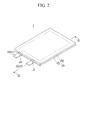
- FIG. 2 illustrates a perspective view of an assembly of the rechargeable battery of FIG. 1
- a rechargeable battery 1 according to a first exemplary embodiment may include an electrode assembly 110 for charging and discharging, a case (for example, referred to as a "pouch 120" hereafter) housing the electrode assembly 110 and an electrolyte, and a lead tab connected to the electrode assembly 110 and drawn, e.g., extending, out of the pouch 120.
- a case for example, referred to as a "pouch 120" hereafter
- a lead tab connected to the electrode assembly 110 and drawn, e.g., extending, out of the pouch 120.
- the electrode assembly 110 may be formed in a jelly-roll type by winding a first electrode 11 (for convenience, referred to as a "positive electrode”) and a second electrode 12 (for convenience, referred to as a "negative electrode”) with a separator 13 therebetween.
- the separator 13 may be a polymer film transmitting lithium ions.
- the first electrode 11, separator 13 and the second electrode 12 may be stacked.
- the lead tab may include a first electrode tab 14 connected to the first electrode 11 and a second electrode tab 15 connected to the second electrode 12.
- the first electrode tab (for convenience, referred to as a "positive electrode tab") may be connected to the positive electrode 11 and the second electrode tab (for convenience, referred to as a "negative electrode tab”) may be connected to the negative electrode 12.
- FIG 3 illustrates a cross-sectional view taken along III - III in FIG. 2
- FIG. 4 illustrates a cross-sectional view of disassembled electrodes used in the electrode assembly of FIG. 3 .
- the separator 13 is not shown in FIG. 4 .
- the positive electrode 11 may have a coated region 11a formed by coating a current collector 11c that may be a metallic thin plate 11c with an active material, and an uncoated region 11b that may be an exposed current collector not coated with an active material.
- the current collector 11c of the positive electrode 11 may be made of Al and the positive electrode tab 14 connected to the positive electrode 11 may be made of Al.
- the negative electrode 11 may have a coated region 12a formed by coating a current collector 12c that may be a metallic thin plate with an active material different from the active material of the positive electrode 11, and an uncoated region 12b that may be an exposed current collector not coated with an active material.
- the current collector 12 of the negative electrode 12 may be made of Cu
- the negative electrode tab 15 connected to the negative electrode 12 may be made of Cu.
- the positive and negative electrode tabs 14 and 15 may include respectively inner tabs 141 and 151 connected to the positive and negative electrodes 11 and 12 and drawn out of the electrode assembly 110, and outer tabs 142 and 152 connected to the inner tabs 141 and 151 outside the electrode assembly 110 and drawn out of the pouch 120.
- the inner tabs 141 and 151 of the positive and negative electrode tabs 14 and 15 may be welded to the uncoated regions 11b and 12b not coated with an active material of the positive and negative electrodes 11 and 12 and may be drawn out of the electrode assembly 110, and the outer tabs 142 and 152 may be welded to the inner tabs 141 and 151 outside the electrode assembly 110.
- FIG. 5 illustrates a side view schematically of the connection relationship between a lead tab and the electrode assembly of FIG. 3 .
- the negative electrode tab 15 will be described without the positive electrode tab 14.
- the inner tab 151 may have a first thickness t1 and the outer tab 152 may have a second thickness t2 larger than the first thickness t1.
- the second thickness t2 of the outer tab 152 may be set larger than the first thickness t1 of the inner tab 151 and smaller than ten times the first thickness t1 (t1 ⁇ t2 ⁇ 10t1).
- the inner tab 151 may be provided for the electrode assembly 110 and may have the first thickness t1 that may be relatively small, and flatness of the electrode assembly 100 may be improved.
- the second thickness t2 of the outer tab 152 may be set larger than the first thickness t1 of the inner tab 151 and smaller than five times the first thickness t1 (t1 ⁇ t2 ⁇ 5t1).
- the thickness difference between the outer tab 152 and the inner tab 151 may be reduced, and the thickness difference between the welding portions of the outer tab 152 and the inner tab 151 may be reduced.
- the positive and negative electrode tabs 14 and 15 may be drawn out from the same side (the left side in FIGS. 1 to 3 ) of the electrode assembly 110. In an embodiment, the positive and negative electrode tabs may be disposed on opposite sides (the left and right sides in FIGS. 1 to 3 ) of the electrode assembly.
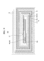
- FIG. 6 illustrates a top plan view schematically of the connection relationship between the lead tab and the electrode assembly of FIG. 3 .
- the electrode assembly 110 may have a first length L1 in the longitudinal direction (x-axis direction) of a spiral-wound center.
- the inner tab 151 may be drawn out in the longitudinal direction (x-axis direction) of the spiral-wound center of the electrode assembly 110.
- the inner tabs 141 and 151 may have a second length L2 in the longitudinal direction (x-axis direction) of the spiral-wound center.
- the second length L2 of the inner tabs 141 and 151 may be set smaller than a half of the first length L1 of the electrode assembly 110 (0 ⁇ L2 ⁇ L1/2).
- the second length L2 of the inner tabs 141 and 151 may be reduced within a range allowing for a sufficient current for charging and discharging of the electrode assembly 110.
- the inner tabs 141 and 151 and the outer tabs 142 and 152 may define a first width W1 in a direction (y-axis direction) crossing the longitudinal direction of the spiral-wound center of the electrode assembly 110.
- the inner tab 151 may be set to have the first width W1 and the outer tab 152 may be set to have the second width W2 larger than the first width W1.
- the second width W2 of the outer tab 142 and 152 may be set larger than 0.9 times the first width W1 of the inner tabs 141 and 151 and smaller than 1.5 times the first width W1 (0.9W1 ⁇ W2 ⁇ 1.5W1).
- the inner tab 141 of the positive electrode tab 14 and the inner tab 151 of the negative electrode tab 15 may define a first tab gap G1 in the y-axis direction
- the outer tab 142 of the positive electrode tab 14 and the outer tab 152 of the negative electrode tab 15 may define a second tag gap G2 in the y-axis direction.
- the inner tabs 141 and 151 may be connected to the electrode assembly 110, and the first tab gap G1 may be fixed and the second tab gap G2 may depend on the second width W2 of the outer tabs 142 and 152 and the welding positions of the outer tabs 142 and 152 with respect to the inner tabs 141 and 151.
- the second width W2 may be variable with respect to the first width W1, and the welding positions of the outer tabs 142 and the 152 may be changed in the y-axis direction from the inner tabs 141 and 151.
- a second tab gap G2 may be variously set in the electrode assemblies 110 having the same size, and there may not be a need for changing the design of the current collectors 11c and 12c of the positive and negative electrodes 11 and 12.
- the electrode assembly 110 may further include an insulating tape covering its wound outer side.
- the inner tabs 141 and 151 may protrude out of the insulating tape 19, and they may be welded to the outer tabs 142 and 152 after taping.
- FIG. 7 illustrates a cross-sectional view of a method of connecting an inner tab to an electrode.
- an inner tab 241 of a lead tab 24 may be welded to a current collector 21c exposed by removing a coated region 212 (compare the top and middle drawings of FIG. 7 ) made of an active material from an electrode 21.
- the capacity of the coated region 212 may further increase at the electrode 21.
- the pouch 120 may house the electrode assembly 110 and the outer side of the pouch 120 may be thermally bonded, and the rechargeable battery 1 may be achieved.
- the outer tabs 142 and 152 of the positive and negative electrode tabs 14 and 15 may be coated with insulating members 143 and 153 and drawn out of the pouch 120 through the thermal-bonding portion.
- the insulating members 143 and 153 may electrically insulate the outer tabs 142 and 152 of the positive and negative electrode tabs 14 and 15 and may electrically insulate the outer tabs 142 and 152 of the positive and negative electrode tabs 14 and 15 and the pouch 120 from each other.
- the pouch 120 may have a multilayered sheet structure covering the outer side of the electrode assembly 110.
- the pouch 120 may include a polymer sheet 121 that may form the inner side of the pouch 120 and may perform insulating and thermal bonding, a PET (Polyethylene Terephthalate) sheet that may perform protection by forming an outer side, a nylon sheet or a PET-nylon composite sheet 122 (hereafter, a "nylon sheet” may be exemplified, e.g., may be used, for convenience), and a metal sheet 123 that may provide mechanical strength.
- the metal sheet 123 may be disposed between the polymer sheet 121 and the nylon sheet 122, and for example, it may be an aluminum sheet.
- the pouch 120 may include a first exterior material 201 receiving the electrode assembly 110 and a second exterior material 202 covering the electrode assembly 110 and thermally bonded to the first exterior material 201 outside the electrode assembly 110.
- the first and second exterior materials 201 and 202 may be formed by the polymer sheet 121, the nylon sheet 122, and the metal sheet 123 in the same layered structure.
- first exterior material 201 may be concave to receive the electrode assembly 110, and the second exterior material 202 may be flat to cover the electrode assembly 110 inside the first exterior material 201.
- the second exterior material may be connected to the first exterior material.
- a second exemplary embodiment is described hereafter. Different components from the components of the first exemplary embodiment will be described.
- FIG. 8 illustrates an exploded perspective view of a rechargeable battery according to a second exemplary embodiment.
- a rechargeable battery 3 according to the second exemplary embodiment may house an electrode assembly 310 and an electrolyte in a pouch 130 formed by thermally bonding a first exterior material 301 and a second exterior material 302.
- Lead tabs for example, inner tabs 341 and 351 of positive and negative electrode tabs 34 and 35 may be drawn out in a direction (y-axis direction) perpendicular to the longitudinal direction (x-axis or winding axis direction) of the spiral-wound center of the electrode assembly 310.
- the positive and negative electrodes 31 and 32 may have uncoated regions 31b and 32b at the spiral-wound ends.
- the inner tabs 341 and 351 may be welded to the uncoated regions 31b and 32b, and the outer tabs 342 and 352 may be welded to the ends of the inner tabs 341 and 351.
- the uncoated regions 31b and 32b of the positive and negative electrodes 31 and 32 may be formed by removing portions of coated regions 31a and 32a, as shown in FIG. 7 , and connected to the inner tabs 341 and 351.
- An insulating tape 39 may be attached to the ends of the positive and negative electrodes 31 and 32 between the welding portions of the uncoated regions 31b and 32b and the inner tabs 341 and 351.
- FIG. 9 illustrates a cross-sectional view of an electrode assembly in a rechargeable battery according to a third exemplary embodiment.
- an inner tab 441 of a positive electrode tab 44 may have a first thickness and may be welded to an uncoated region 41b on a portion of a positive electrode 41
- an inner tab 451 of a negative electrode tab 45 may have a first thickness and may be welded to an uncoated region 42b at the start end of a negative electrode 42.
- the inner tab 441 may be welded, corresponding to the thickness of a coated region 41a welded and removed at the uncoated region 41b at a portion of the positive electrode 41, and it may not increase the thickness of the electrode assembly 410.
- An outer tab having a second thickness may be welded to the ends of the inner tabs 441 and 451 (see the first exemplary embodiment).
- the inner tabs 441 and 451 of the positive and negative electrode tabs 44 and 45 may have the first thickness that may be relatively small, may be disposed inside the electrode assembly 410, and may be connected to the outer tabs outside the electrode assembly 410, and the flatness of the electrode assembly 410 may be improved.
- the inner tabs 441 and 451 and the outer tabs may define a first width W41 in the longitudinal direction of the spiral-wound center of the electrode assembly 410.
- the inner tab 451 may be set to have the first width W41 and the outer tab 452 may be set to have the second width W42 that may be larger than the first width W41.
- the inner tabs 441 and 451 may be connected to the electrode assembly 410, and the first tab gap G41 may be fixed and the second tab gap G42 may depend on the second width W2 of the outer tabs and the welding positions of the outer tabs with respect to the inner tabs 441 and 451.
- rechargeable batteries having a pouch are equally applied to angular rechargeable batteries and may improve the flatness of electrode assemblies and the capacity of cells. It may be possible to easily adjust the tab gaps between lead tabs in electrode assemblies.
- rechargeable batteries may include an electrode assembly for charging and discharging, a pouch housing the electrode assembly, and a lead tab drawn out of the pouch from the electrode assembly.
- the electrode assembly may be formed by welding a lead tab to an uncoated region and winding an electrode plate.
- the portion with the lead tab may be thicker than the other portion in the electrode assembly.
- the position of the lead tab may reduce flatness of the rechargeable battery, and the increase in thickness, for example, due to the lead tab, may decrease the capacity of a cell and may deform the electrode assembly.
- a lead tab may be welded to the outermost side of an electrode assembly, a pouch housing the electrode assembly may deform outward in the shape of the lead tab, and the external appearance of the cell may be deteriorated.
- the electrode assembly may be manufactured by winding the electrode plate with the lead tab connected, and the tab gap between lead tabs (for example, a cathode tab and an anode tab) may be fixed in the electrode assembly.
- the tab gaps may not be adjusted to be different in electrode assemblies having the same size, and it may be necessary to redesign the electrode plate to change the tab gaps.
- a rechargeable battery that may have improved flatness of an electrode assembly, capacity of a cell, and external appearance of the cell, even if a lead tab is on a side.
- a rechargeable battery that may allow for easy adjustment of tab gaps between lead tabs in an electrode assembly.
- a lead tab may be composed of a thin inner tab and a thick outer tab and the inner tab may be disposed inside an electrode and drawn out of the electrode assembly, and it may be possible to improve flatness of the electrode assembly and the external appearance of a cell.
- the thickness of a lead tab may be smaller inside than outside the electrode assembly, it may be possible to increase the area coated with an active material in comparison to a conventional electrode assembly with a lead tab inside the electrode assembly, and the capacity of a cell may be increased.
- An outer tab that may be wider than an inner tab may be welded to the inner tab outside the electrode assembly, and it may be possible to easily adjust the tab gaps defined by outer tabs.
- Embodiments relate to a rechargeable battery that may have a lead tab, which may be connected to an electrode assembly, outside a pouch.
- embodiments of the invention can provide a rechargeable battery, comprising: an electrode assembly including first and second electrodes with a separator therebetween; a pouch housing the electrode assembly; and a first lead tab connected to the first electrode and drawn out of the pouch, wherein the first lead tab includes a first inner tab having a first thickness, connected to the first electrode, and drawn out of the electrode assembly.
- the first lead tab can include a first outer tab having a second thickness larger than the first thickness, connected to the first inner tab outside the electrode assembly, and drawn out of the pouch.
- first electrode, separator and the second electrode are wound (e.g. spirally wound). In other embodiments, the first electrode, separator and the second electrode may be stacked.
- the rechargeable battery comprises a second lead tab connected to the second electrode and drawn out of the pouch, wherein the second lead tab includes a second inner tab having a first thickness, connected to the second electrode, and drawn out of the electrode assembly.
- the second lead tab includes a second outer tab having a second thickness larger than the first thickness, connected to the first inner tab outside the electrode assembly, and drawn out of the pouch.
- the second lead tab may have corresponding dimensions (e.g. the same length, width and/or thickness) to the first lead tab.
- the electrode assembly may have long sides and short sides, with a longitudinal direction being defined as being generally parallel to the long sides.
- the first and second lead tabs may extend in various directions, for example either parallel or perpendicular to the longitudinal direction.
- embodiments of the invention can provide a rechargeable battery that has thinner lead tabs inside the electrode assembly than the lead tabs that protrude outside the pouch.
- the inner lead tabs may be thinner than the outer lead tabs.
Abstract
Description
- Embodiments relate to a rechargeable battery.
- A demand for rechargeable batteries as an energy source may increase with technical developments of mobile devices. Rechargeable batteries are batteries that may be repeatedly charged and discharged, unlike primary batteries.
- Small-capacitance rechargeable batteries may be used for small portable electronic devices such as a mobile phone, a laptop computer, and a camcorder, and large-capacitance batteries may be used as a power source for driving a motor in hybrid vehicles and electric vehicles.
- Embodiments may be realized by providing a rechargeable battery, including an electrode assembly including wound electrodes with a separator therebetween; a pouch housing the electrode assembly; and lead tabs connected to the electrodes and drawn out of the pouch, the lead tabs including an inner tab having a first thickness, connected to the electrode, and drawn out of the electrode assembly.
- The lead tabs may include an outer tab having a second thickness larger than the first thickness, connected to the inner tab outside the electrode assembly, and drawn out of the pouch.
- The second thickness may be larger than the first thickness and smaller than ten times the first thickness.
- The second thickness may be larger than the first thickness and smaller than five times the first thickness.
- In a direction perpendicular to a longitudinal direction of a spiral-wound center of the electrode assembly, the inner tab may have a first width, and the outer tab may have a second width larger than the first width.
- The second width may be larger than 0.9 times the first width and smaller than 1.5 times the first width.
- The electrode assembly may have a first length in a longitudinal direction of a spiral-wound center, and the inner tab may be drawn out in the longitudinal direction of the spiral-wound center.
- The inner tab may have a second length in the longitudinal direction of the spiral-wound center, and the second length may be larger than zero and smaller than half of the first length.
- The lead tabs may include a first electrode tab connected to a first electrode of the electrodes and a second electrode tab connected to a second electrode.
- The inner tab may include an inner tab of the first electrode tab and an inner tab of the second electrode tab; a first tab gap defined by the inner tab of the first electrode tab and the inner tab of the second electrode tab may be fixed, and a second tab gap defined by an outer tab of the first electrode tab and an outer tab of the second electrode tab may be variable.
- In the electrodes, a first electrode may include aluminum and a second electrode may include copper, and in the inner tab, an inner tab of the first electrode may include aluminum and may be connected to the first electrode and an inner tab of the second electrode may include copper and may be connected to the second electrode.
- The inner tab of the lead tab may be welded to uncoated regions not coated with an active material in the first electrode and the second electrode.
- The inner tab of the lead tab may be welded to current collectors exposed by removing an active material from the first electrode and the second electrode.
- The electrode assembly may further include an insulating tape covering its outer side.
- The inner tab of the lead tab may protrude out of the insulating tape.
- The inner tab of the lead tab may be drawn out in a direction perpendicular to a longitudinal direction of a spiral-wound center of the electrode assembly.
- The lead tabs may include a first electrode tab connected to a first electrode of the electrodes and a second electrode tab connected to a second electrode, a first tab gap defined by an inner tab of the first electrode tab and an inner tab of the second electrode tab may be fixed in the longitudinal direction of the spiral-wound center, and a second tab gap defined by an outer tab of the first electrode tab and an outer tab of the second electrode tab may be variable in the longitudinal direction of the spiral-wound center.
- The lead tabs may include a first electrode tab connected to a first electrode of the electrodes and a second electrode tab connected to a second electrode, and the inner tab may be welded to an uncoated region at a portion on at least one of the first electrode and the second electrode.
- According to an aspect of the invention, there is provided a rechargeable battery as set out in
claim 1. Preferred features are set out in claims 2 to 15. - Features will become apparent to those of skill in the art by describing in detail exemplary embodiments with reference to the attached drawings in which:
-
FIG. 1 illustrates an exploded perspective view of a rechargeable battery according to a first exemplary embodiment; -
FIG. 2 illustrates a perspective view of an assembly of the rechargeable battery ofFIG. 1 ; -
FIG 3 illustrates a cross-sectional view taken along III - III inFIG. 2 ; -
FIG. 4 illustrates a cross-sectional view of disassembled electrodes used in the electrode assembly ofFIG. 3 ; -
FIG. 5 illustrates a side view schematically of the connection relationship between a lead tab and the electrode assembly ofFIG. 3 ; -
FIG. 6 illustrates a top plan view schematically of the connection relationship between the lead tab and the electrode assembly ofFIG. 3 ; -
FIG. 7 illustrates a cross-sectional view of a method of connecting an inner tab to an electrode; -
FIG. 8 illustrates an exploded perspective view of a rechargeable battery according to a second exemplary embodiment; and -
FIG. 9 illustrates a cross-sectional view of an electrode assembly in a rechargeable battery according to a third exemplary embodiment. - Example embodiments will now be described more fully hereinafter with reference to the accompanying drawings; however, they may be embodied in different forms and should not be construed as limited to the embodiments set forth herein. Rather, these embodiments are provided so that this disclosure will be thorough and complete, and will fully convey exemplary implementations to those skilled in the art.
- In the drawing figures, the dimensions of layers and regions may be exaggerated for clarity of illustration. Like reference numerals refer to like elements throughout.
-
FIG. 1 illustrates an exploded perspective view of a rechargeable battery according to a first exemplary embodiment, andFIG. 2 illustrates a perspective view of an assembly of the rechargeable battery ofFIG. 1 . Referring toFIGS. 1 and2 , arechargeable battery 1 according to a first exemplary embodiment may include anelectrode assembly 110 for charging and discharging, a case (for example, referred to as a "pouch 120" hereafter) housing theelectrode assembly 110 and an electrolyte, and a lead tab connected to theelectrode assembly 110 and drawn, e.g., extending, out of thepouch 120. - The
electrode assembly 110 may be formed in a jelly-roll type by winding a first electrode 11 (for convenience, referred to as a "positive electrode") and a second electrode 12 (for convenience, referred to as a "negative electrode") with aseparator 13 therebetween. Theseparator 13 may be a polymer film transmitting lithium ions. In other embodiments, thefirst electrode 11,separator 13 and thesecond electrode 12 may be stacked. - The lead tab may include a
first electrode tab 14 connected to thefirst electrode 11 and asecond electrode tab 15 connected to thesecond electrode 12. The first electrode tab (for convenience, referred to as a "positive electrode tab") may be connected to thepositive electrode 11 and the second electrode tab (for convenience, referred to as a "negative electrode tab") may be connected to thenegative electrode 12. -
FIG 3 illustrates a cross-sectional view taken along III - III inFIG. 2 , andFIG. 4 illustrates a cross-sectional view of disassembled electrodes used in the electrode assembly ofFIG. 3 . For convenience, theseparator 13 is not shown inFIG. 4 . - Referring to
FIGS. 3 and 4 , thepositive electrode 11 may have a coatedregion 11a formed by coating acurrent collector 11c that may be a metallicthin plate 11c with an active material, and anuncoated region 11b that may be an exposed current collector not coated with an active material. For example, thecurrent collector 11c of thepositive electrode 11 may be made of Al and thepositive electrode tab 14 connected to thepositive electrode 11 may be made of Al. - The
negative electrode 11 may have a coatedregion 12a formed by coating acurrent collector 12c that may be a metallic thin plate with an active material different from the active material of thepositive electrode 11, and anuncoated region 12b that may be an exposed current collector not coated with an active material. For example, thecurrent collector 12 of thenegative electrode 12 may be made of Cu, and thenegative electrode tab 15 connected to thenegative electrode 12 may be made of Cu. - The positive and
negative electrode tabs inner tabs negative electrodes electrode assembly 110, andouter tabs inner tabs electrode assembly 110 and drawn out of thepouch 120. - Referring to
FIGS. 1 and4 , theinner tabs negative electrode tabs uncoated regions negative electrodes electrode assembly 110, and theouter tabs inner tabs electrode assembly 110. -
FIG. 5 illustrates a side view schematically of the connection relationship between a lead tab and the electrode assembly ofFIG. 3 . For convenience, thenegative electrode tab 15 will be described without thepositive electrode tab 14. Referring toFIG. 5 , theinner tab 151 may have a first thickness t1 and theouter tab 152 may have a second thickness t2 larger than the first thickness t1. - For example, the second thickness t2 of the
outer tab 152 may be set larger than the first thickness t1 of theinner tab 151 and smaller than ten times the first thickness t1 (t1 < t2 < 10t1). Theinner tab 151 may be provided for theelectrode assembly 110 and may have the first thickness t1 that may be relatively small, and flatness of the electrode assembly 100 may be improved. - In an embodiment, the second thickness t2 of the
outer tab 152 may be set larger than the first thickness t1 of theinner tab 151 and smaller than five times the first thickness t1 (t1 < t2 < 5t1). The thickness difference between theouter tab 152 and theinner tab 151 may be reduced, and the thickness difference between the welding portions of theouter tab 152 and theinner tab 151 may be reduced. - The positive and
negative electrode tabs FIGS. 1 to 3 ) of theelectrode assembly 110. In an embodiment, the positive and negative electrode tabs may be disposed on opposite sides (the left and right sides inFIGS. 1 to 3 ) of the electrode assembly. -
FIG. 6 illustrates a top plan view schematically of the connection relationship between the lead tab and the electrode assembly ofFIG. 3 . Referring toFIGS. 5 and 6 , theelectrode assembly 110 may have a first length L1 in the longitudinal direction (x-axis direction) of a spiral-wound center. Theinner tab 151 may be drawn out in the longitudinal direction (x-axis direction) of the spiral-wound center of theelectrode assembly 110. - The
inner tabs inner tabs inner tabs electrode assembly 110. - As the second length L2 of the
inner tabs electrode assembly 110, for example, due to the first thickness t1 of theinner tabs electrode assembly 110, may be minimized. - The
inner tabs outer tabs electrode assembly 110. Theinner tab 151 may be set to have the first width W1 and theouter tab 152 may be set to have the second width W2 larger than the first width W1. - For example, the second width W2 of the
outer tab inner tabs - The
inner tab 141 of thepositive electrode tab 14 and theinner tab 151 of thenegative electrode tab 15 may define a first tab gap G1 in the y-axis direction, and theouter tab 142 of thepositive electrode tab 14 and theouter tab 152 of thenegative electrode tab 15 may define a second tag gap G2 in the y-axis direction. - The
inner tabs electrode assembly 110, and the first tab gap G1 may be fixed and the second tab gap G2 may depend on the second width W2 of theouter tabs outer tabs inner tabs - The second width W2 may be variable with respect to the first width W1, and the welding positions of the
outer tabs 142 and the 152 may be changed in the y-axis direction from theinner tabs electrode assemblies 110 having the same size, and there may not be a need for changing the design of thecurrent collectors negative electrodes - The
electrode assembly 110 may further include an insulating tape covering its wound outer side. Theinner tabs tape 19, and they may be welded to theouter tabs -
FIG. 7 illustrates a cross-sectional view of a method of connecting an inner tab to an electrode. Referring toFIG. 7 , aninner tab 241 of alead tab 24 may be welded to acurrent collector 21c exposed by removing a coated region 212 (compare the top and middle drawings ofFIG. 7 ) made of an active material from anelectrode 21. The capacity of thecoated region 212 may further increase at theelectrode 21. - Referring to
FIGS. 1 and2 , thepouch 120 may house theelectrode assembly 110 and the outer side of thepouch 120 may be thermally bonded, and therechargeable battery 1 may be achieved. Theouter tabs negative electrode tabs members pouch 120 through the thermal-bonding portion. The insulatingmembers outer tabs negative electrode tabs outer tabs negative electrode tabs pouch 120 from each other. - The
pouch 120 may have a multilayered sheet structure covering the outer side of theelectrode assembly 110. For example, thepouch 120 may include apolymer sheet 121 that may form the inner side of thepouch 120 and may perform insulating and thermal bonding, a PET (Polyethylene Terephthalate) sheet that may perform protection by forming an outer side, a nylon sheet or a PET-nylon composite sheet 122 (hereafter, a "nylon sheet" may be exemplified, e.g., may be used, for convenience), and ametal sheet 123 that may provide mechanical strength. Themetal sheet 123 may be disposed between thepolymer sheet 121 and thenylon sheet 122, and for example, it may be an aluminum sheet. - The
pouch 120 may include a firstexterior material 201 receiving theelectrode assembly 110 and a secondexterior material 202 covering theelectrode assembly 110 and thermally bonded to the firstexterior material 201 outside theelectrode assembly 110. The first and secondexterior materials polymer sheet 121, thenylon sheet 122, and themetal sheet 123 in the same layered structure. - For example, the first
exterior material 201 may be concave to receive theelectrode assembly 110, and the secondexterior material 202 may be flat to cover theelectrode assembly 110 inside the firstexterior material 201. In an embodiment, the second exterior material may be connected to the first exterior material. - A second exemplary embodiment is described hereafter. Different components from the components of the first exemplary embodiment will be described.
-
FIG. 8 illustrates an exploded perspective view of a rechargeable battery according to a second exemplary embodiment. Referring toFIG. 8 , arechargeable battery 3 according to the second exemplary embodiment may house anelectrode assembly 310 and an electrolyte in apouch 130 formed by thermally bonding a firstexterior material 301 and a secondexterior material 302. - Lead tabs, for example,
inner tabs negative electrode tabs electrode assembly 310. For this purpose, the positive and negative electrodes 31 and 32 may haveuncoated regions inner tabs uncoated regions outer tabs 342 and 352 may be welded to the ends of theinner tabs - The
uncoated regions coated regions FIG. 7 , and connected to theinner tabs tape 39 may be attached to the ends of the positive and negative electrodes 31 and 32 between the welding portions of theuncoated regions inner tabs -
FIG. 9 illustrates a cross-sectional view of an electrode assembly in a rechargeable battery according to a third exemplary embodiment. Referring toFIG. 9 , in anelectrode assembly 410 of a rechargeable battery according to the third exemplary embodiment, aninner tab 441 of apositive electrode tab 44 may have a first thickness and may be welded to anuncoated region 41b on a portion of apositive electrode 41, and aninner tab 451 of anegative electrode tab 45 may have a first thickness and may be welded to anuncoated region 42b at the start end of anegative electrode 42. - The
inner tab 441 may be welded, corresponding to the thickness of acoated region 41a welded and removed at theuncoated region 41b at a portion of thepositive electrode 41, and it may not increase the thickness of theelectrode assembly 410. An outer tab having a second thickness may be welded to the ends of theinner tabs 441 and 451 (see the first exemplary embodiment). - The
inner tabs negative electrode tabs electrode assembly 410, and may be connected to the outer tabs outside theelectrode assembly 410, and the flatness of theelectrode assembly 410 may be improved. - The
inner tabs electrode assembly 410. Theinner tab 451 may be set to have the first width W41 and the outer tab 452 may be set to have the second width W42 that may be larger than the first width W41. - The
inner tabs electrode assembly 410, and the first tab gap G41 may be fixed and the second tab gap G42 may depend on the second width W2 of the outer tabs and the welding positions of the outer tabs with respect to theinner tabs - Although exemplary embodiments have described rechargeable batteries having a pouch, they are equally applied to angular rechargeable batteries and may improve the flatness of electrode assemblies and the capacity of cells. It may be possible to easily adjust the tab gaps between lead tabs in electrode assemblies.
- By way of summation and review, rechargeable batteries may include an electrode assembly for charging and discharging, a pouch housing the electrode assembly, and a lead tab drawn out of the pouch from the electrode assembly. The electrode assembly may be formed by welding a lead tab to an uncoated region and winding an electrode plate.
- The portion with the lead tab may be thicker than the other portion in the electrode assembly. The position of the lead tab may reduce flatness of the rechargeable battery, and the increase in thickness, for example, due to the lead tab, may decrease the capacity of a cell and may deform the electrode assembly.
- A lead tab may be welded to the outermost side of an electrode assembly, a pouch housing the electrode assembly may deform outward in the shape of the lead tab, and the external appearance of the cell may be deteriorated.
- The electrode assembly may be manufactured by winding the electrode plate with the lead tab connected, and the tab gap between lead tabs (for example, a cathode tab and an anode tab) may be fixed in the electrode assembly. The tab gaps may not be adjusted to be different in electrode assemblies having the same size, and it may be necessary to redesign the electrode plate to change the tab gaps.
- Provided is a rechargeable battery that may have improved flatness of an electrode assembly, capacity of a cell, and external appearance of the cell, even if a lead tab is on a side. Provided is a rechargeable battery that may allow for easy adjustment of tab gaps between lead tabs in an electrode assembly.
- As described above, according to an exemplary embodiment, a lead tab may be composed of a thin inner tab and a thick outer tab and the inner tab may be disposed inside an electrode and drawn out of the electrode assembly, and it may be possible to improve flatness of the electrode assembly and the external appearance of a cell.
- The thickness of a lead tab may be smaller inside than outside the electrode assembly, it may be possible to increase the area coated with an active material in comparison to a conventional electrode assembly with a lead tab inside the electrode assembly, and the capacity of a cell may be increased.
- An outer tab that may be wider than an inner tab may be welded to the inner tab outside the electrode assembly, and it may be possible to easily adjust the tab gaps defined by outer tabs.
- Embodiments relate to a rechargeable battery that may have a lead tab, which may be connected to an electrode assembly, outside a pouch.
- As discussed above, embodiments of the invention can provide a rechargeable battery, comprising: an electrode assembly including first and second electrodes with a separator therebetween; a pouch housing the electrode assembly; and a first lead tab connected to the first electrode and drawn out of the pouch, wherein the first lead tab includes a first inner tab having a first thickness, connected to the first electrode, and drawn out of the electrode assembly. The first lead tab can include a first outer tab having a second thickness larger than the first thickness, connected to the first inner tab outside the electrode assembly, and drawn out of the pouch.
- In some embodiments, the first electrode, separator and the second electrode are wound (e.g. spirally wound). In other embodiments, the first electrode, separator and the second electrode may be stacked.
- In some embodiments, the rechargeable battery comprises a second lead tab connected to the second electrode and drawn out of the pouch, wherein the second lead tab includes a second inner tab having a first thickness, connected to the second electrode, and drawn out of the electrode assembly. In some such embodiments, the second lead tab includes a second outer tab having a second thickness larger than the first thickness, connected to the first inner tab outside the electrode assembly, and drawn out of the pouch. The second lead tab may have corresponding dimensions (e.g. the same length, width and/or thickness) to the first lead tab.
- The electrode assembly may have long sides and short sides, with a longitudinal direction being defined as being generally parallel to the long sides. The first and second lead tabs may extend in various directions, for example either parallel or perpendicular to the longitudinal direction.
- Hence, embodiments of the invention can provide a rechargeable battery that has thinner lead tabs inside the electrode assembly than the lead tabs that protrude outside the pouch. In other words, the inner lead tabs may be thinner than the outer lead tabs.
- Example embodiments have been disclosed herein, and although specific terms are employed, they are used and are to be interpreted in a generic and descriptive sense only and not for purpose of limitation. In some instances, as would be apparent to one of skill in the art as of the filing of the present application, features, characteristics, and/or elements described in connection with a particular embodiment may be used singly or in combination with features, characteristics, and/or elements described in connection with other embodiments unless otherwise specifically indicated. Accordingly, it will be understood by those of skill in the art that various changes in form and details may be made without departing from the scope of the present invention as set forth in the following claims.
Claims (15)
- A rechargeable battery, comprising:an electrode assembly including a first electrode and a second electrode with a separator therebetween;a pouch housing the electrode assembly; anda first lead tab connected to the first electrode and extending out of the pouch,wherein the first lead tab includes a first inner tab having a first thickness, connected to the first electrode, and extending out of the electrode assembly; and a first outer tab having a second thickness larger than the first thickness, connected to the first inner tab outside the electrode assembly, and extending out of the pouch.
- The rechargeable battery as claimed in claim 1, wherein the first electrode, separator and the second electrode are wound.
- The rechargeable battery as claimed in claim 1 or 2, wherein the second thickness is larger than the first thickness and smaller than ten times the first thickness.
- The rechargeable battery as claimed in any one of claims 1 to 3, wherein the second thickness is larger than the first thickness and smaller than five times the first thickness.
- The rechargeable battery as claimed in any one of claims 1 to 4, wherein, in a direction perpendicular to a longitudinal direction of the electrode assembly, the inner tab has a first width, and the outer tab has a second width larger than the first width;
optionally wherein the second width is larger than 0.9 times the first width and smaller than 1.5 times the first width. - The rechargeable battery as claimed in any one of claims 1 to 5, wherein the electrode assembly has a first length in a longitudinal direction of the electrode assembly, and the first inner tab extends in the longitudinal direction.
- The rechargeable battery as claimed in claim 6, wherein the first inner tab has a second length in the longitudinal direction, and the second length is larger than zero and smaller than half of the first length.
- The rechargeable battery as claimed in any one of claims 1 to 7, further comprising:a second lead tab connected to the second electrode and extending out of the pouch,wherein the second lead tab includes a second inner tab having a first thickness, connected to the second electrode, and extending out of the electrode assembly; and a second outer tab having a second thickness larger than the first thickness, connected to the first inner tab outside the electrode assembly, and extending out of the pouch.
- The rechargeable battery as claimed in claim 8, wherein the second lead tab has corresponding dimensions to the first lead tab.
- The rechargeable battery as claimed in claim 8 or 9, wherein:a first tab gap defined by the first inner tab and the second inner tab is fixed, anda second tab gap defined by the first outer tab and the second outer tab of the second electrode tab is variable.
- The rechargeable battery as claimed in claim 10, wherein the first and second inner tabs extend out in a direction parallel to a longitudinal direction of the electrode assembly, and the first and second tab gaps are gaps in a direction perpendicular to the longitudinal direction of the electrode assembly; or
wherein the first and second inner tabs extend out in a direction perpendicular to a longitudinal direction of the electrode assembly, and the first and second tab gaps are gaps in a direction parallel to the longitudinal direction of the electrode assembly. - The rechargeable battery as claimed in any one of claims 8 to 11, wherein the first electrode includes aluminum and the second electrode includes copper, and the first inner tab comprises aluminum and the second inner tab comprises copper.
- The rechargeable battery as claimed in any one of claims 8 to 12, wherein the first inner tab is welded to an uncoated region of the first electrode that is not coated with an active material, and the second inner tab is welded to an uncoated region of the second electrode that is not coated with an active material.
- The rechargeable battery as claimed in any one of claims 8 to 13, wherein the first and second inner tabs are welded to current collectors exposed by removing an active material from the first electrode and the second electrode.
- The rechargeable battery as claimed in any one of claims 1 to 14, wherein the electrode assembly further includes an insulating tape covering its outer side;
optionally wherein the first inner tab protrudes out of the insulating tape.
Applications Claiming Priority (1)
| Application Number | Priority Date | Filing Date | Title |
|---|---|---|---|
| KR1020150011561A KR101784743B1 (en) | 2015-01-23 | 2015-01-23 | Rechargeable battery |
Publications (2)
| Publication Number | Publication Date |
|---|---|
| EP3048656A1 true EP3048656A1 (en) | 2016-07-27 |
| EP3048656B1 EP3048656B1 (en) | 2018-10-31 |
Family
ID=54557339
Family Applications (1)
| Application Number | Title | Priority Date | Filing Date |
|---|---|---|---|
| EP15195228.0A Active EP3048656B1 (en) | 2015-01-23 | 2015-11-18 | Rechargeable battery |
Country Status (4)
| Country | Link |
|---|---|
| US (1) | US20160218386A1 (en) |
| EP (1) | EP3048656B1 (en) |
| KR (1) | KR101784743B1 (en) |
| CN (1) | CN105826509B (en) |
Cited By (2)
| Publication number | Priority date | Publication date | Assignee | Title |
|---|---|---|---|---|
| EP3512019A4 (en) * | 2016-09-09 | 2020-05-13 | Samsung SDI Co., Ltd. | Secondary battery |
| US20220059909A1 (en) * | 2019-01-21 | 2022-02-24 | Samsung Electronics Co., Ltd. | Battery including adhesive layer formed on extended region of separator of electrode assembly, and electronic device comprising same |
Families Citing this family (7)
| Publication number | Priority date | Publication date | Assignee | Title |
|---|---|---|---|---|
| CN205376656U (en) * | 2016-01-20 | 2016-07-06 | 宁德新能源科技有限公司 | Secondary battery |
| CN106025377B (en) * | 2016-08-01 | 2019-02-12 | 东莞新能源科技有限公司 | A kind of takeup type battery core |
| KR102167431B1 (en) * | 2016-08-19 | 2020-10-19 | 주식회사 엘지화학 | Battery Cell Assembly Combined by Single Electrode Lead with Different Thickness |
| KR102654626B1 (en) * | 2016-10-27 | 2024-04-04 | 삼성에스디아이 주식회사 | Secondary battery |
| KR102124640B1 (en) * | 2016-12-21 | 2020-06-18 | 주식회사 엘지화학 | Electrode Assembly Comprising Electrode Lead Coupled to Long Side Portion |
| KR20200134062A (en) * | 2019-05-21 | 2020-12-01 | 삼성에스디아이 주식회사 | Rechargeable battery |
| KR20220072353A (en) | 2020-11-25 | 2022-06-02 | 에스케이온 주식회사 | Electrode, Manufacturing method for electrode, and Secondary cell having the same |
Citations (3)
| Publication number | Priority date | Publication date | Assignee | Title |
|---|---|---|---|---|
| EP1901387A2 (en) * | 2006-09-08 | 2008-03-19 | NEC TOKIN Corporation | Method for production of stacked battery |
| EP2325927A1 (en) * | 2009-11-18 | 2011-05-25 | Samsung SDI Co., Ltd | Secondary battery |
| US20130224562A1 (en) * | 2012-02-29 | 2013-08-29 | Semiconductor Energy Laboratory Co., Ltd. | Power storage device |
Family Cites Families (15)
| Publication number | Priority date | Publication date | Assignee | Title |
|---|---|---|---|---|
| JP3729164B2 (en) * | 2002-08-05 | 2005-12-21 | 日産自動車株式会社 | Automotive battery |
| JP4211322B2 (en) * | 2002-08-26 | 2009-01-21 | 日産自動車株式会社 | Multilayer battery, battery pack, battery module and electric vehicle |
| JP4175215B2 (en) * | 2003-08-08 | 2008-11-05 | 日産自動車株式会社 | Bipolar battery, assembled battery, composite assembled battery, and vehicle using assembled battery or composite assembled battery |
| US7745042B2 (en) * | 2004-01-09 | 2010-06-29 | Panasonic Corporation | Lithium ion secondary battery |
| KR101023870B1 (en) * | 2009-01-08 | 2011-03-22 | 삼성에스디아이 주식회사 | Pouch Type Lithium Secondary battery |
| KR101367751B1 (en) * | 2009-09-28 | 2014-02-26 | 주식회사 엘지화학 | secondary battery and manufacturing method thereof |
| US8889286B2 (en) * | 2009-10-01 | 2014-11-18 | Samsung Sdi Co., Ltd. | Secondary battery and method of fabricating secondary battery |
| US8435669B2 (en) * | 2009-10-08 | 2013-05-07 | Tdk Corporation | Electro-chemical device and method for manufacturing the same |
| KR101165507B1 (en) * | 2009-11-27 | 2012-07-13 | 삼성에스디아이 주식회사 | Secondary Battery |
| EP2634832B1 (en) * | 2010-06-21 | 2015-08-05 | Kabushiki Kaisha Toshiba | Battery |
| KR101147237B1 (en) * | 2010-07-12 | 2012-05-18 | 삼성에스디아이 주식회사 | Electrode assembly and rechargeable battery including the same |
| KR20120009577A (en) * | 2010-07-19 | 2012-02-02 | 주식회사 엘지화학 | Secondary electric cell with differential lead structure |
| KR101100948B1 (en) * | 2010-07-29 | 2011-12-29 | 삼성에스디아이 주식회사 | Secondary battery |
| KR20120031606A (en) * | 2010-09-27 | 2012-04-04 | 주식회사 엘지화학 | Electrode lead whose protection layer for anti-corrosion is selectively formed, and secondary battery comprising thereof |
| US20120183825A1 (en) * | 2011-01-14 | 2012-07-19 | Seung-Hun Lee | Secondary battery and method of manufacturing the same |
-
2015
- 2015-01-23 KR KR1020150011561A patent/KR101784743B1/en active IP Right Grant
- 2015-07-23 US US14/806,689 patent/US20160218386A1/en not_active Abandoned
- 2015-08-21 CN CN201510520272.9A patent/CN105826509B/en active Active
- 2015-11-18 EP EP15195228.0A patent/EP3048656B1/en active Active
Patent Citations (3)
| Publication number | Priority date | Publication date | Assignee | Title |
|---|---|---|---|---|
| EP1901387A2 (en) * | 2006-09-08 | 2008-03-19 | NEC TOKIN Corporation | Method for production of stacked battery |
| EP2325927A1 (en) * | 2009-11-18 | 2011-05-25 | Samsung SDI Co., Ltd | Secondary battery |
| US20130224562A1 (en) * | 2012-02-29 | 2013-08-29 | Semiconductor Energy Laboratory Co., Ltd. | Power storage device |
Cited By (3)
| Publication number | Priority date | Publication date | Assignee | Title |
|---|---|---|---|---|
| EP3512019A4 (en) * | 2016-09-09 | 2020-05-13 | Samsung SDI Co., Ltd. | Secondary battery |
| US20220059909A1 (en) * | 2019-01-21 | 2022-02-24 | Samsung Electronics Co., Ltd. | Battery including adhesive layer formed on extended region of separator of electrode assembly, and electronic device comprising same |
| US11949127B2 (en) * | 2019-01-21 | 2024-04-02 | Samsung Electronics Co., Ltd. | Battery including adhesive layer formed on extended region of separator of electrode assembly, and electronic device comprising same |
Also Published As
| Publication number | Publication date |
|---|---|
| CN105826509A (en) | 2016-08-03 |
| KR101784743B1 (en) | 2017-11-06 |
| KR20160091199A (en) | 2016-08-02 |
| CN105826509B (en) | 2019-11-08 |
| EP3048656B1 (en) | 2018-10-31 |
| US20160218386A1 (en) | 2016-07-28 |
Similar Documents
| Publication | Publication Date | Title |
|---|---|---|
| EP3048656B1 (en) | Rechargeable battery | |
| JP5779828B2 (en) | Electrode assembly having step, battery cell, battery pack and device including the same | |
| JP5508313B2 (en) | Electrode assembly and secondary battery using the same | |
| US9269984B2 (en) | Electrode assembly and rechargeable battery using the same | |
| US10026934B2 (en) | Flexible rechargeable battery | |
| US20200028200A1 (en) | Method for producing an electrode unit for a battery cell and electrode unit | |
| US10374249B2 (en) | Rechargeable battery | |
| EP2445048B1 (en) | Rechargeable battery | |
| US8021781B2 (en) | Jelly-roll type electrode assembly and secondary battery employing the same | |
| KR102275332B1 (en) | Rechargeable battery | |
| EP3065204B1 (en) | Rechargeable battery | |
| US9819046B2 (en) | Rechargeable battery | |
| CN105977516B (en) | Rechargeable battery | |
| US8703342B2 (en) | Electrode assembly, rechargeable battery including the same, and method of manufacturing an electrode thereof | |
| KR20180032083A (en) | Rechageable battery | |
| US10177351B2 (en) | Rechargeable battery | |
| US20150255775A1 (en) | Stepwise electrode assembly including one-sided negative electrode | |
| EP3211688A1 (en) | Rechargeable battery | |
| CN105576190B (en) | Rechargeable battery | |
| US20160268580A1 (en) | Rechargeable battery | |
| US11495832B2 (en) | Electrochemical cell | |
| US11329338B2 (en) | Rechargeable battery | |
| US20170069902A1 (en) | Secondary battery | |
| KR20170049275A (en) | Electrode assembly and rechargeable battery including the same | |
| JP2019114397A (en) | Manufacturing method for power storage element, and power storage element |
Legal Events
| Date | Code | Title | Description |
|---|---|---|---|
| PUAI | Public reference made under article 153(3) epc to a published international application that has entered the european phase |
Free format text: ORIGINAL CODE: 0009012 |
|
| AK | Designated contracting states |
Kind code of ref document: A1 Designated state(s): AL AT BE BG CH CY CZ DE DK EE ES FI FR GB GR HR HU IE IS IT LI LT LU LV MC MK MT NL NO PL PT RO RS SE SI SK SM TR |
|
| AX | Request for extension of the european patent |
Extension state: BA ME |
|
| 17P | Request for examination filed |
Effective date: 20170123 |
|
| RBV | Designated contracting states (corrected) |
Designated state(s): AL AT BE BG CH CY CZ DE DK EE ES FI FR GB GR HR HU IE IS IT LI LT LU LV MC MK MT NL NO PL PT RO RS SE SI SK SM TR |
|
| 17Q | First examination report despatched |
Effective date: 20170802 |
|
| GRAP | Despatch of communication of intention to grant a patent |
Free format text: ORIGINAL CODE: EPIDOSNIGR1 |
|
| RIC1 | Information provided on ipc code assigned before grant |
Ipc: H01M 10/04 20060101ALN20180523BHEP Ipc: H01M 2/22 20060101ALI20180523BHEP Ipc: H01M 2/02 20060101AFI20180523BHEP Ipc: H01M 2/30 20060101ALN20180523BHEP Ipc: H01M 2/26 20060101ALI20180523BHEP |
|
| INTG | Intention to grant announced |
Effective date: 20180614 |
|
| GRAS | Grant fee paid |
Free format text: ORIGINAL CODE: EPIDOSNIGR3 |
|
| GRAA | (expected) grant |
Free format text: ORIGINAL CODE: 0009210 |
|
| AK | Designated contracting states |
Kind code of ref document: B1 Designated state(s): AL AT BE BG CH CY CZ DE DK EE ES FI FR GB GR HR HU IE IS IT LI LT LU LV MC MK MT NL NO PL PT RO RS SE SI SK SM TR |
|
| REG | Reference to a national code |
Ref country code: CH Ref legal event code: EP Ref country code: GB Ref legal event code: FG4D |
|
| REG | Reference to a national code |
Ref country code: AT Ref legal event code: REF Ref document number: 1060460 Country of ref document: AT Kind code of ref document: T Effective date: 20181115 |
|
| REG | Reference to a national code |
Ref country code: DE Ref legal event code: R096 Ref document number: 602015019014 Country of ref document: DE |
|
| REG | Reference to a national code |
Ref country code: IE Ref legal event code: FG4D |
|
| REG | Reference to a national code |
Ref country code: NL Ref legal event code: MP Effective date: 20181031 |
|
| REG | Reference to a national code |
Ref country code: LT Ref legal event code: MG4D |
|
| REG | Reference to a national code |
Ref country code: AT Ref legal event code: MK05 Ref document number: 1060460 Country of ref document: AT Kind code of ref document: T Effective date: 20181031 |
|
| PG25 | Lapsed in a contracting state [announced via postgrant information from national office to epo] |
Ref country code: BG Free format text: LAPSE BECAUSE OF FAILURE TO SUBMIT A TRANSLATION OF THE DESCRIPTION OR TO PAY THE FEE WITHIN THE PRESCRIBED TIME-LIMIT Effective date: 20190131 Ref country code: FI Free format text: LAPSE BECAUSE OF FAILURE TO SUBMIT A TRANSLATION OF THE DESCRIPTION OR TO PAY THE FEE WITHIN THE PRESCRIBED TIME-LIMIT Effective date: 20181031 Ref country code: LT Free format text: LAPSE BECAUSE OF FAILURE TO SUBMIT A TRANSLATION OF THE DESCRIPTION OR TO PAY THE FEE WITHIN THE PRESCRIBED TIME-LIMIT Effective date: 20181031 Ref country code: NO Free format text: LAPSE BECAUSE OF FAILURE TO SUBMIT A TRANSLATION OF THE DESCRIPTION OR TO PAY THE FEE WITHIN THE PRESCRIBED TIME-LIMIT Effective date: 20190131 Ref country code: AT Free format text: LAPSE BECAUSE OF FAILURE TO SUBMIT A TRANSLATION OF THE DESCRIPTION OR TO PAY THE FEE WITHIN THE PRESCRIBED TIME-LIMIT Effective date: 20181031 Ref country code: LV Free format text: LAPSE BECAUSE OF FAILURE TO SUBMIT A TRANSLATION OF THE DESCRIPTION OR TO PAY THE FEE WITHIN THE PRESCRIBED TIME-LIMIT Effective date: 20181031 Ref country code: IS Free format text: LAPSE BECAUSE OF FAILURE TO SUBMIT A TRANSLATION OF THE DESCRIPTION OR TO PAY THE FEE WITHIN THE PRESCRIBED TIME-LIMIT Effective date: 20190228 Ref country code: ES Free format text: LAPSE BECAUSE OF FAILURE TO SUBMIT A TRANSLATION OF THE DESCRIPTION OR TO PAY THE FEE WITHIN THE PRESCRIBED TIME-LIMIT Effective date: 20181031 Ref country code: HR Free format text: LAPSE BECAUSE OF FAILURE TO SUBMIT A TRANSLATION OF THE DESCRIPTION OR TO PAY THE FEE WITHIN THE PRESCRIBED TIME-LIMIT Effective date: 20181031 Ref country code: PL Free format text: LAPSE BECAUSE OF FAILURE TO SUBMIT A TRANSLATION OF THE DESCRIPTION OR TO PAY THE FEE WITHIN THE PRESCRIBED TIME-LIMIT Effective date: 20181031 |
|
| PG25 | Lapsed in a contracting state [announced via postgrant information from national office to epo] |
Ref country code: SE Free format text: LAPSE BECAUSE OF FAILURE TO SUBMIT A TRANSLATION OF THE DESCRIPTION OR TO PAY THE FEE WITHIN THE PRESCRIBED TIME-LIMIT Effective date: 20181031 Ref country code: AL Free format text: LAPSE BECAUSE OF FAILURE TO SUBMIT A TRANSLATION OF THE DESCRIPTION OR TO PAY THE FEE WITHIN THE PRESCRIBED TIME-LIMIT Effective date: 20181031 Ref country code: GR Free format text: LAPSE BECAUSE OF FAILURE TO SUBMIT A TRANSLATION OF THE DESCRIPTION OR TO PAY THE FEE WITHIN THE PRESCRIBED TIME-LIMIT Effective date: 20190201 Ref country code: NL Free format text: LAPSE BECAUSE OF FAILURE TO SUBMIT A TRANSLATION OF THE DESCRIPTION OR TO PAY THE FEE WITHIN THE PRESCRIBED TIME-LIMIT Effective date: 20181031 Ref country code: RS Free format text: LAPSE BECAUSE OF FAILURE TO SUBMIT A TRANSLATION OF THE DESCRIPTION OR TO PAY THE FEE WITHIN THE PRESCRIBED TIME-LIMIT Effective date: 20181031 Ref country code: PT Free format text: LAPSE BECAUSE OF FAILURE TO SUBMIT A TRANSLATION OF THE DESCRIPTION OR TO PAY THE FEE WITHIN THE PRESCRIBED TIME-LIMIT Effective date: 20190301 |
|
| REG | Reference to a national code |
Ref country code: CH Ref legal event code: PL |
|
| PG25 | Lapsed in a contracting state [announced via postgrant information from national office to epo] |
Ref country code: IT Free format text: LAPSE BECAUSE OF FAILURE TO SUBMIT A TRANSLATION OF THE DESCRIPTION OR TO PAY THE FEE WITHIN THE PRESCRIBED TIME-LIMIT Effective date: 20181031 Ref country code: CZ Free format text: LAPSE BECAUSE OF FAILURE TO SUBMIT A TRANSLATION OF THE DESCRIPTION OR TO PAY THE FEE WITHIN THE PRESCRIBED TIME-LIMIT Effective date: 20181031 Ref country code: LU Free format text: LAPSE BECAUSE OF NON-PAYMENT OF DUE FEES Effective date: 20181118 Ref country code: DK Free format text: LAPSE BECAUSE OF FAILURE TO SUBMIT A TRANSLATION OF THE DESCRIPTION OR TO PAY THE FEE WITHIN THE PRESCRIBED TIME-LIMIT Effective date: 20181031 |
|
| REG | Reference to a national code |
Ref country code: DE Ref legal event code: R097 Ref document number: 602015019014 Country of ref document: DE |
|
| REG | Reference to a national code |
Ref country code: BE Ref legal event code: MM Effective date: 20181130 |
|
| REG | Reference to a national code |
Ref country code: IE Ref legal event code: MM4A |
|
| PG25 | Lapsed in a contracting state [announced via postgrant information from national office to epo] |
Ref country code: LI Free format text: LAPSE BECAUSE OF NON-PAYMENT OF DUE FEES Effective date: 20181130 Ref country code: CH Free format text: LAPSE BECAUSE OF NON-PAYMENT OF DUE FEES Effective date: 20181130 Ref country code: SM Free format text: LAPSE BECAUSE OF FAILURE TO SUBMIT A TRANSLATION OF THE DESCRIPTION OR TO PAY THE FEE WITHIN THE PRESCRIBED TIME-LIMIT Effective date: 20181031 Ref country code: EE Free format text: LAPSE BECAUSE OF FAILURE TO SUBMIT A TRANSLATION OF THE DESCRIPTION OR TO PAY THE FEE WITHIN THE PRESCRIBED TIME-LIMIT Effective date: 20181031 Ref country code: RO Free format text: LAPSE BECAUSE OF FAILURE TO SUBMIT A TRANSLATION OF THE DESCRIPTION OR TO PAY THE FEE WITHIN THE PRESCRIBED TIME-LIMIT Effective date: 20181031 Ref country code: SK Free format text: LAPSE BECAUSE OF FAILURE TO SUBMIT A TRANSLATION OF THE DESCRIPTION OR TO PAY THE FEE WITHIN THE PRESCRIBED TIME-LIMIT Effective date: 20181031 Ref country code: MC Free format text: LAPSE BECAUSE OF FAILURE TO SUBMIT A TRANSLATION OF THE DESCRIPTION OR TO PAY THE FEE WITHIN THE PRESCRIBED TIME-LIMIT Effective date: 20181031 |
|
| PLBE | No opposition filed within time limit |
Free format text: ORIGINAL CODE: 0009261 |
|
| STAA | Information on the status of an ep patent application or granted ep patent |
Free format text: STATUS: NO OPPOSITION FILED WITHIN TIME LIMIT |
|
| 26N | No opposition filed |
Effective date: 20190801 |
|
| PG25 | Lapsed in a contracting state [announced via postgrant information from national office to epo] |
Ref country code: IE Free format text: LAPSE BECAUSE OF NON-PAYMENT OF DUE FEES Effective date: 20181118 Ref country code: SI Free format text: LAPSE BECAUSE OF FAILURE TO SUBMIT A TRANSLATION OF THE DESCRIPTION OR TO PAY THE FEE WITHIN THE PRESCRIBED TIME-LIMIT Effective date: 20181031 |
|
| PG25 | Lapsed in a contracting state [announced via postgrant information from national office to epo] |
Ref country code: BE Free format text: LAPSE BECAUSE OF NON-PAYMENT OF DUE FEES Effective date: 20181130 |
|
| PG25 | Lapsed in a contracting state [announced via postgrant information from national office to epo] |
Ref country code: MT Free format text: LAPSE BECAUSE OF NON-PAYMENT OF DUE FEES Effective date: 20181118 |
|
| PG25 | Lapsed in a contracting state [announced via postgrant information from national office to epo] |
Ref country code: TR Free format text: LAPSE BECAUSE OF FAILURE TO SUBMIT A TRANSLATION OF THE DESCRIPTION OR TO PAY THE FEE WITHIN THE PRESCRIBED TIME-LIMIT Effective date: 20181031 |
|
| PG25 | Lapsed in a contracting state [announced via postgrant information from national office to epo] |
Ref country code: MK Free format text: LAPSE BECAUSE OF NON-PAYMENT OF DUE FEES Effective date: 20181031 Ref country code: HU Free format text: LAPSE BECAUSE OF FAILURE TO SUBMIT A TRANSLATION OF THE DESCRIPTION OR TO PAY THE FEE WITHIN THE PRESCRIBED TIME-LIMIT; INVALID AB INITIO Effective date: 20151118 Ref country code: CY Free format text: LAPSE BECAUSE OF FAILURE TO SUBMIT A TRANSLATION OF THE DESCRIPTION OR TO PAY THE FEE WITHIN THE PRESCRIBED TIME-LIMIT Effective date: 20181031 |
|
| REG | Reference to a national code |
Ref country code: DE Ref legal event code: R079 Ref document number: 602015019014 Country of ref document: DE Free format text: PREVIOUS MAIN CLASS: H01M0002020000 Ipc: H01M0050100000 |
|
| P01 | Opt-out of the competence of the unified patent court (upc) registered |
Effective date: 20230528 |
|
| PGFP | Annual fee paid to national office [announced via postgrant information from national office to epo] |
Ref country code: GB Payment date: 20231102 Year of fee payment: 9 |
|
| PGFP | Annual fee paid to national office [announced via postgrant information from national office to epo] |
Ref country code: FR Payment date: 20231108 Year of fee payment: 9 Ref country code: DE Payment date: 20231031 Year of fee payment: 9 |