US8465869B2 - Rechargeable battery - Google Patents
Rechargeable battery Download PDFInfo
- Publication number
- US8465869B2 US8465869B2 US12/654,557 US65455709A US8465869B2 US 8465869 B2 US8465869 B2 US 8465869B2 US 65455709 A US65455709 A US 65455709A US 8465869 B2 US8465869 B2 US 8465869B2
- Authority
- US
- United States
- Prior art keywords
- core
- electrode assembly
- rechargeable battery
- support portions
- avoidance
- Prior art date
- Legal status (The legal status is an assumption and is not a legal conclusion. Google has not performed a legal analysis and makes no representation as to the accuracy of the status listed.)
- Active, expires
Links
Images


Classifications
-
- H—ELECTRICITY
- H01—ELECTRIC ELEMENTS
- H01M—PROCESSES OR MEANS, e.g. BATTERIES, FOR THE DIRECT CONVERSION OF CHEMICAL ENERGY INTO ELECTRICAL ENERGY
- H01M10/00—Secondary cells; Manufacture thereof
- H01M10/04—Construction or manufacture in general
- H01M10/0431—Cells with wound or folded electrodes
-
- H—ELECTRICITY
- H01—ELECTRIC ELEMENTS
- H01M—PROCESSES OR MEANS, e.g. BATTERIES, FOR THE DIRECT CONVERSION OF CHEMICAL ENERGY INTO ELECTRICAL ENERGY
- H01M10/00—Secondary cells; Manufacture thereof
- H01M10/05—Accumulators with non-aqueous electrolyte
- H01M10/058—Construction or manufacture
- H01M10/0587—Construction or manufacture of accumulators having only wound construction elements, i.e. wound positive electrodes, wound negative electrodes and wound separators
-
- H—ELECTRICITY
- H01—ELECTRIC ELEMENTS
- H01M—PROCESSES OR MEANS, e.g. BATTERIES, FOR THE DIRECT CONVERSION OF CHEMICAL ENERGY INTO ELECTRICAL ENERGY
- H01M10/00—Secondary cells; Manufacture thereof
- H01M10/04—Construction or manufacture in general
- H01M10/0422—Cells or battery with cylindrical casing
-
- Y—GENERAL TAGGING OF NEW TECHNOLOGICAL DEVELOPMENTS; GENERAL TAGGING OF CROSS-SECTIONAL TECHNOLOGIES SPANNING OVER SEVERAL SECTIONS OF THE IPC; TECHNICAL SUBJECTS COVERED BY FORMER USPC CROSS-REFERENCE ART COLLECTIONS [XRACs] AND DIGESTS
- Y02—TECHNOLOGIES OR APPLICATIONS FOR MITIGATION OR ADAPTATION AGAINST CLIMATE CHANGE
- Y02E—REDUCTION OF GREENHOUSE GAS [GHG] EMISSIONS, RELATED TO ENERGY GENERATION, TRANSMISSION OR DISTRIBUTION
- Y02E60/00—Enabling technologies; Technologies with a potential or indirect contribution to GHG emissions mitigation
- Y02E60/10—Energy storage using batteries
-
- Y—GENERAL TAGGING OF NEW TECHNOLOGICAL DEVELOPMENTS; GENERAL TAGGING OF CROSS-SECTIONAL TECHNOLOGIES SPANNING OVER SEVERAL SECTIONS OF THE IPC; TECHNICAL SUBJECTS COVERED BY FORMER USPC CROSS-REFERENCE ART COLLECTIONS [XRACs] AND DIGESTS
- Y02—TECHNOLOGIES OR APPLICATIONS FOR MITIGATION OR ADAPTATION AGAINST CLIMATE CHANGE
- Y02P—CLIMATE CHANGE MITIGATION TECHNOLOGIES IN THE PRODUCTION OR PROCESSING OF GOODS
- Y02P70/00—Climate change mitigation technologies in the production process for final industrial or consumer products
- Y02P70/50—Manufacturing or production processes characterised by the final manufactured product
Definitions
- Embodiments relate to a rechargeable battery. More particularly, embodiments relate to a rechargeable battery having an improved core structure.
- a rechargeable battery is capable of being repeatedly charged and discharged, unlike a primary battery.
- a low-capacity single cell rechargeable battery may generally be used for a portable small electronic device, e.g., a mobile phone, a laptop computer, or a camcorder.
- a large capacity rechargeable battery may be formed of a plurality of cells connected in a pack. The large capacity rechargeable battery has been widely used for a power source for, e.g., driving a motor of a hybrid electric vehicle.
- Rechargeable batteries have been manufactured in various shapes, e.g., a cylindrical shape and a rectangular shape. A plurality of such rechargeable batteries may be coupled in series so as to form a large capacity rechargeable battery module to be used to, e.g., drive a motor of an electric vehicle that requires large power.
- the rechargeable battery may include an electrode assembly having a positive electrode, a negative electrode and a separator therebetween, a case for housing the electrode assembly and a cap assembly for closing and sealing the case.
- the positive electrode and the negative electrode may form a band shape extending in one direction, and an uncoated region may be formed at one end of the positive electrode and the negative electrode along their lengths.
- the positive electrode uncoated region and the negative electrode uncoated region may be disposed in different directions.
- a negative electrode current collecting plate may be coupled to the negative electrode uncoated region, and a positive electrode current collecting plate may be coupled to the positive electrode uncoated region.
- the positive electrode current collecting plate may be electrically connected to the cap assembly to provide an external current path.
- the electrode assembly may expand and contract repeatedly, such that charge and discharge efficiencies may be deteriorated, thereby reducing the output of the rechargeable battery. Also, life-span may decrease and an unstable reaction may occur. Accordingly, overall life-span of the rechargeable battery may be reduced.
- Embodiments are therefore directed to a rechargeable battery, which substantially overcomes the problems due to the limitations and disadvantages of the related art.
- a rechargeable battery including an electrode assembly having an inner surface and including a positive electrode, a negative electrode, and a separator interposed therebetween, a case having a space for internally housing the electrode assembly, a cap assembly coupled to the case and electrically connected to the electrode assembly, and a core inside the electrode assembly.
- the core may have a length and include a plurality of support portions contacting the inner surface of the electrode assembly, and may have a plurality of avoidance surfaces between the support portions and separated from the inner surface of the electrode assembly.
- the rechargeable battery may further include a buffer space between the avoidance surfaces and the inner surface of the electrode assembly.
- the core may include a hollow portion penetrating the core along its length.
- the core may have outer edges and surfaces between the outer edges, the support portions may include the outer edges of the core and the avoidance surfaces may include the surfaces between the outer edges.
- the avoidance surfaces may be planar.
- the support portions may include a curved surface in contact with the inner surface of the electrode assembly.
- the avoidance surfaces may include a curved surface curved away from the inner surface of the electrode assembly.
- the support portions may be at ends of the core, the avoidance surfaces may include recess portions and the recess portions may be disposed along the length of the core between the support portions.
- the core may include a center axis and a distance from the center axis of the core to the recess portions may be shorter than a distance from the center axis of the core to the support portions.
- the core may have a center axis, and a distance from the recess portions to the center of the core and a distance between the recess portions may decrease from an end of one of the recess portions toward a center of the recess portion.
- the avoidance surfaces may include a hole extending along a length of the core.
- the core may have two ends, support portions may be disposed at the ends of the core, and a hole may extend between along the length of the core the support portions.
- the core may have two ends and large cross-section members having a large horizontal cross-section at both ends of the core, and an elastic deforming member having a horizontal cross-section smaller than the horizontal cross-section of the large cross-section members extending along the length of the core between the large cross-section members.
- the electrode assembly may have a spiral shape.
- the case may have a cylinder shape.
- FIG. 1 illustrates an exploded perspective view of a rechargeable battery according to an embodiment
- FIG. 2 illustrates a perspective view of a core of a rechargeable battery according to embodiment
- FIG. 3 illustrates a horizontal cross-sectional view of the core shown in FIG. 2 taken along the line III-III;
- FIG. 4 illustrates a graph showing variation of fractional capacity according to capacity throughput of a rechargeable battery according to an embodiment
- FIG. 5A to FIG. 5C illustrate perspective views of cores according to an embodiment
- FIG. 6 illustrates a perspective view of a core of a rechargeable battery according to another embodiment
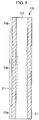
- FIG. 7 illustrates a horizontal cross-sectional view of the core shown in FIG. 6 taken along the line VII-VII;
- FIG. 8 illustrates a vertical cross-sectional view of the core shown in FIG. 7 taken along the line VIII-VIII;
- FIG. 9 illustrates a perspective view of a core of a rechargeable battery according to yet another embodiment
- FIG. 10 illustrates a horizontal cross-sectional view of the core of FIG. 9 taken along the line X-X;
- FIG. 11 illustrates a perspective view of a core of a rechargeable battery according to yet another embodiment
- FIG. 12 illustrates a horizontal cross-sectional view of the core of FIG. 11 taken along the line XII-XII;
- FIG. 13 illustrates a perspective view of a core of a rechargeable battery according to still another embodiment
- FIG. 14 illustrates a horizontal cross-sectional view of the core of FIG. 13 taken along the line XIV-XIV.
- each of the expressions “at least one,” “one or more,” and “and/or” are open-ended expressions that are both conjunctive and disjunctive in operation.
- each of the expressions “at least one of A, B, and C,” “at least one of A, B, or C,” “one or more of A, B, and C,” “one or more of A, B, or C” and “A, B, and/or C” includes the following meanings: A alone; B alone; C alone; both A and B together; both A and C together; both B and C together; and all three of A, B, and C together.
- the expression “or” is not an “exclusive or” unless it is used in conjunction with the term “either.”
- the expression “A, B, or C” includes A alone; B alone; C alone; both A and B together; both A and C together; both B and C together; and all three of A, B, and C together
- the expression “either A, B, or C” means one of A alone, B alone, and C alone, and does not mean any of both A and B together; both A and C together; both B and C together; and all three of A, B, and C together.
- a metal may represent a single compound, e.g., aluminum, or multiple compounds in combination, e.g., aluminum mixed with nickel.
- FIG. 1 illustrates an exploded perspective view of a rechargeable battery according to an embodiment.
- a rechargeable battery 100 may include an electrode assembly 110 having a positive electrode 112 , a negative electrode 113 and a separator 114 interposed therebetween, and having a case 120 having an opening at one end thereof for housing the electrode assembly 110 along with an electrolyte solution.
- a cap assembly 140 for closing and sealing the case 120 may be disposed at the opening of the case 120 with a gasket 144 therebetween.
- the case 120 may include conductive metal, e.g., aluminum, aluminum alloy or nickel-plated steel.
- the case 120 may be formed in a cylindrical shape having an internal space for housing the electrode assembly 110 . After inserting the cap assembly 140 into the case 120 , the cap assembly 140 may be fixed in the case 120 by clamping. During clamping, a binding member 123 and a clamping member 125 may be formed in the case.
- the electrode assembly 110 may be formed in a cylindrical shape by winding the positive electrode 112 , the separator 114 and the negative electrode 113 in a spiral shape after stacking the positive electrode 112 , the separator 114 and the negative electrode 113 .
- the structure of the electrode assembly 110 is not limited thereto.
- the electrode assembly 110 may be formed in other shapes, e.g., a rectangular shape.
- the electrode assembly 110 may include a space at the center thereof, and a core 160 may be disposed in the space to maintain the shape of the center of the electrode assembly 110 .
- a positive electrode uncoated region 112 a may be formed at a top end of the positive electrode 112 , and may not be coated with positive electrode active material.
- the positive electrode uncoated region 112 a may be electrically connected to a positive electrode current collecting plate 138 .
- a negative electrode uncoated region 113 a may be formed at a bottom end of the negative electrode 113 , and may not be coated with negative electrode active material.
- the negative electrode uncoated region 113 a may be electrically connected to a negative electrode current collecting plate 132 .
- the negative electrode 113 may include a current collector made of, e.g., copper or aluminum, coated with negative electrode active material.
- the positive electrode 112 may include a current collector made of, e.g., aluminum, coated with positive electrode active material.
- the negative electrode active material may include, e.g., carbon-based active material, silicon-based active material or titanium-based active material.
- the positive electrode active material may include, e.g., carbon-based active material, nickel-based active material, manganese-based active material, cobalt-based active material, ternary-based active material or olivine-based active material.
- the positive electrode current collecting plate 138 may be disposed at an upper part, and the negative electrode current collecting plate 132 may be disposed at a lower part in an embodiment, the embodiments are not limited thereto.
- the positive electrode current collecting plate 138 may be disposed at the lower part and the negative electrode current collecting plate 132 may be disposed at the upper part.
- the cap assembly 140 may include a cap upper 143 and a vent plate 142 .
- the cap upper 143 may include a protruding outer terminal 143 a and a vent 143 b .
- the vent plate 142 may include a notch 142 a disposed under the cap upper 143 .
- the notch 142 a may break at a predetermined pressure in order to discharge excessive gas pressure.
- the vent plate 142 may also interrupt an electric connection of the electrode assembly 110 and the cap upper 143 at the predetermined pressure.
- a positive temperature coefficient element 141 may be disposed between the cap upper 143 and the vent plate 142 .
- the positive temperature coefficient element 141 may increase electrical resistance thereof infinitely if it exceeds a predetermined temperature. Thus, if the rechargeable battery 100 reaches a temperature higher than a predetermined value, the positive temperature coefficient element 141 may interrupt flow of charge and discharge current.
- a convex member 142 b may be formed at the center of the vent plate 142 .
- the convex member 142 b may protrude in a downward direction.
- a sub-plate 147 may be attached at a bottom surface of the convex member 142 b through, e.g., welding.
- a cap lower 146 may be disposed between the vent plate 142 and the sub-plate 147 .
- the cap lower 146 may have, e.g., a circular shape.
- the cap lower 146 may include a hole at a center thereof to order to insert the convex member 142 b therein.
- An insulating member 145 may be disposed between the cap lower 146 and the vent plate 142 .
- the insulating member 145 may insulate the cap lower 146 from the vent plate 142 .
- the insulating member 145 may include a hole at a center thereof to insert the convex member 142 b therein. Accordingly, the convex member 142 b of the vent plate 142 may be easily joined with the sub-plate 147 through the holes.
- the sub-plate 147 may be coupled to the convex member 142 b and the cap lower 146 , and the cap lower 146 may be electrically connected to the electrode assembly 110 through a lead member 150 .
- the vent plate 142 may couple to the cap upper 143 to transfer current to the outer terminal 143 a of the cap upper 143 .
- FIG. 2 illustrates a perspective view of a core of a rechargeable battery according to an embodiment.
- FIG. 3 illustrates a horizontal cross-sectional view of the core shown in FIG. 2 taken along the line III-III.
- the core 160 may have, e.g., a rectangular pillar shape.
- a hollow portion 162 may be formed inside the core 160 .
- the hollow portion 162 may penetrate the core 160 along its length.
- the hollow portion 162 may have a hexagon cross-section and may extend from one end of the core 160 to the other end. However, the embodiments are not limited thereto.
- the hollow portion 162 may have a cross-section formed in various suitable shapes, e.g., a polygonal shape, an oval shape, etc.
- the hollow portion 162 may provide a gas passage.
- the core 160 having the rectangular pillar shape may include a support portion 161 .
- An edge of the core 160 contacting the inner surface of the electrode assembly 110 may form the support portion 161 .
- An outer surface of the core 160 may be planar, and portions thereof may be separated from an inner surface of the electrode assembly 110 to form an avoidance surface 165 .
- a buffer space 164 may be formed between the avoidance surface 165 and the inner surface of the electrode assembly 110 .
- the buffer space 164 may function as a buffer when the electrode assembly 110 expands.
- the electrode assembly 110 may gradually expand. Accordingly, the spiral-wound electrode assembly 110 may expand not only externally but also internally. However, since the core 160 may be disposed inside the electrode assembly 110 and may support the electrode assembly 110 , the core 160 may contact the electrode assembly 110 . Therefore, the positive electrode 112 and the negative electrode 113 inside the electrode assembly 110 may be compressed.
- the active material layers may be squeezed. As a result, the rechargeable battery may not be properly charged or discharged. Therefore, the output of the rechargeable battery 100 may deteriorate, and a life-span thereof may be shortened.
- a space may be formed between the electrode assembly 110 and the case 120 according to an embodiment, it may be possible to prevent stress from being concentrated. In contrast, if no space is formed inside the electrode assembly 110 , concentration of stress may seriously deteriorate the positive electrode 112 and the negative electrode 113 . Therefore, overall performance of the rechargeable battery 100 may deteriorate.
- the core 160 is formed to have the rectangular pillar shape of an embodiment, only the support portion, which includes an edge of the rectangular pillar, may contact the inner surface of the electrode assembly 110 . Therefore, the buffer space 164 may be formed between the avoidance surface 165 and the electrode assembly 110 .
- the electrode assembly 110 may expand in the buffer space 164 , stress may be concentrated only at a part contacting with the support portion 161 , and stress may be reduced at the other part by the buffer space 164 . Accordingly, stress may be significantly reduced between the core 160 and the electrode assembly 110 .
- FIG. 4 illustrates a graph showing variation of fractional capacity according to capacity throughput of a triangular (trigonal) pillar core, a rectangular (square) pillar core, and a comparative circular (cylindrical) pillar core.
- the fractional capacity variation according to the capacity throughput is widely used to analyze a life-span of a rechargeable battery. Therefore, a detailed description thereof is omitted.
- the graph shows that the comparative circular pillar core has a fractional throughput that abruptly drops due to deterioration in the electrode assembly as the capacity throughput increases.
- the graph shows that decrease of fractional throughput of the triangular pillar core and the rectangular pillar core may be reduced because deterioration may be reduced in rechargeable batteries including the triangular pillar core and the rectangular pillar core.
- the stress concentration may be significantly reduced in a rechargeable battery according to an embodiment. Therefore, it may be possible to overcome a problem of deterioration of the overall output of the rechargeable battery. Further, the life-span may be improved by preventing the deterioration of the rechargeable battery.
- FIG. 5A to FIG. 5C illustrate perspective views of cores according to embodiments.
- a core may be formed not only in a rectangular pillar core but also in a polygonal pillar core. If the core is formed in a polygonal pillar shape, the edges of the pillar may function as a support portion and an external surface between the edges may function as an avoidance surface.
- a core 191 may be formed in a triangular pillar shape.
- Three support portions 191 a and three avoidance surfaces 191 b may be formed.
- a core 192 may be formed in a pentagonal pillar shape.
- Five support portions 192 a and five avoidance surfaces 192 b may be formed.
- a core 193 may be a hexagonal pillar shape.
- Six support portions 193 a and six avoidance surfaces 193 b are formed.
- FIG. 6 illustrates a perspective view of a core of a rechargeable battery according to another embodiment.
- FIG. 7 illustrates a horizontal cross-sectional view of the core shown in FIG. 6 taken along the line VII-VII.
- a core 210 according to the embodiment may have a rectangular pillar shape and a hollow portion 212 that penetrates the core 210 along its length.
- the core 210 may include holes 217 penetrating an outer surface of the core 210 to the hollow portion 212 .
- the holes 217 may extend along a length of the core, but not the entire length, i.e., both ends of the holes 217 may be disposed inward from ends of the core 210 .
- the holes 217 may be centered along the length of the core 210 .
- the holes 217 may be formed on the avoidance surface 215 to penetrate from the avoidance surface 215 to the hollow portion 212 .
- a plurality of holes 217 may be disposed at a predetermined interval along an external circumference of the core 210 .
- four holes 217 may be arranged at a uniform interval along a circumference of the core 210 .
- one hole 217 may be formed at each avoidance surface 215 .
- the number of holes 217 may be controlled according to the width and shape of the holes 217 .
- the core 210 may be elastically deformed due to the holes 217 .
- the core 210 may be elastically deformed when the electrode assembly 110 pressurizes the core 210 due to expansion of the electrode assembly 110 . Therefore, stress between the core 210 and the electrode assembly 110 may be advantageously reduced.
- a section of the core 210 without holes 217 may have a large cross-section member 210 a having a horizontal cross-sectional area larger than other parts of the core.
- the large cross-section member 210 a may be formed at both ends of the core 210 .
- An elastic deforming member 210 b may be formed between the large cross-section members 210 a .
- the elastic deforming member 210 b may have a horizontal cross-section smaller than the horizontal cross-section of the large cross-section members 210 a .
- the elastic deforming member 210 b may be elastically deformed because the elastic deforming member 210 b may have a smaller horizontal cross-section than the large cross-section member 210 a due to the holes 217 .
- the elastic deforming member 210 b when the electrode assembly 110 expands, the elastic deforming member 210 b may be deformed and bent inwardly, as shown by dashed lines. Since the center portion of the electrode assembly 110 may deform more than peripheral portions when the electrode assembly 110 expands, the elastic deforming member 210 b according to an embodiment may allow the core 210 to deform according to the deformation of the electrode assembly 110 . Therefore, it may prevent stress from excessively concentrating at the support portion 211 .
- a positive electrode current collecting plate 138 and a negative electrode current collecting plate 132 may be fixed at ends of the electrode assembly 110 through, e.g., welding. If the ends of the electrode assembly 110 were to deform inwardly due to deformation at the ends of the core 210 , the electrode assembly 110 may separate from the current collecting plates 132 and 138 . Therefore, the holes 217 may not extend all the way to ends of the core 210 in an embodiment in order to prevent the ends of the electrode assembly 110 from deforming.
- FIG. 9 illustrates a perspective view of a core of a rechargeable battery according to another embodiment.
- FIG. 10 illustrates a horizontal cross-sectional view of the core of FIG. 9 taken along the line X-X.
- a core 230 according to the embodiment may have a hexagon pillar shape and may include a hollow portion 232 that penetrates the core 230 along its length.
- the core 230 may include support portions 231 including edges and avoidance surfaces 235 including surfaces between the support portions 231 .
- Holes 237 may be formed at each edge of the core 230 .
- the holes 237 may penetrate from an outer side of the core 230 to the hollow portion 232 .
- the holes 237 may extend along a length of the core 230 .
- the holes 237 may not extend along the entire length of the core 230 , i.e., both ends of the holes 237 may be disposed inward from the ends of the core 230 .
- the holes 237 are centered along a length of the core 230 .
- Portions with the holes 237 may not contact the electrode assembly 110 . That is, the support portion 231 may not be formed where the core 230 includes the holes 237 . The support portions 231 may be formed only at the ends of the core 230 . Therefore, stress may be generated only at the ends of the electrode assembly 110 . Thus, the stress may be minimized at inner portions of the electrode assembly 110 .
- the holes 237 of the core 230 may allow the core 230 to be elastically deformed. Therefore, the stress between the core 230 and the electrode assembly 110 may be further reduced.
- FIG. 11 illustrates a perspective view of a core of a rechargeable battery according to yet another embodiment.
- FIG. 12 illustrates a horizontal cross-sectional view of the core of FIG. 11 taken along the line XII-XII.
- a core 240 may have a rectangular pillar shape and may include a hollow portion 242 penetrating the core 240 along its length.
- the core 240 may include support portions 241 including edges of the core 240 and avoidance surfaces 245 including surfaces between the edges.
- the support portions 241 may be formed at both ends of the core 240 and recess portions 247 may be formed between the support portions 241 along the length of the core 240 .
- the recess portions 247 may be formed by, e.g., cutting off the edges of the core 240 .
- the recess portions 247 may be formed by cutting off a center portion of the edge, shown by dashed lines, with both ends of the edge remaining on the core 240 .
- the recess portions 247 may form a trench structure in an arc toward an inner side of the core 240 . If a distance D 1 denotes a distance from a center axis 0 of the core 240 to the support portion 241 and a distance D 2 denotes a distance from the center axis 0 to the recess portion 247 , as shown in FIG. 12 , the distance D 1 may be longer than the distance D 2 . Since the recess portion 247 may have an arc shape, the distance D 2 may gradually decrease along a length of the core 240 from an outer end to a center.
- the recess portion 247 at the edge of the core 240 may make the core 240 contact the electrode assembly 110 only at the support portions 241 at ends of the core 240 . Therefore, it may be possible to minimize stress between the core 240 and the electrode assembly 110 . Since a buffer space 244 may also be formed between the recess portion 247 and the electrode assembly 110 , stress may be further minimized by accommodating the expanding electrode assembly 110 . Accordingly, the life-span of a rechargeable battery may be improved by preventing deterioration of the electrode assembly 110 . Deterioration of power output of the rechargeable battery may also be reduced.
- FIG. 13 illustrates a perspective view of a core of a rechargeable battery according to still another embodiment.
- FIG. 14 illustrates a horizontal cross-sectional view of the core of FIG. 13 taken along the line XIV-XIV.
- the core 260 according to the embodiment may have a pillar shape and may include a hollow portion 262 penetrating the core 260 along its length.
- An outer surface of the core 260 may have an arc shape and may include support portions 261 having a rounded outer surface and avoidance surfaces 265 having an inwardly curved surface curved away from an inner surface of the electrode assembly and toward an inner side of the core 260 .
- the support portions 261 may have a rounded outer surface. Curvature of the rounded outer surface of the support portions 261 may be identical to the curvature of an inner circle formed by an inner side surface of the electrode assembly 110 .
- a contact area of the rounded support portions 261 and the electrode assembly 110 may increase compared to an edge, stress generated between the support 261 and the electrode assembly 260 may not be great because the electrode assembly 110 may expand in a space formed between the electrode assembly 110 and the avoidance surfaces 265 .
- the support portion 261 is an edge, stress may be concentrated because the electrode assembly 110 and the support portion 261 contact each other along a line.
- the support portion 261 is curved, the electrode assembly 110 and the support portion 261 contact each other along a curved surface. Therefore, the stress may be distributed.
- the avoidance surface 265 may be curved toward a center of the core 260 , it may be possible to form a buffer space 264 wider than an avoidance surface formed in a plane. Therefore, since a space for accommodating the expanded electrode assembly 110 may become wider, it may be possible to further reduce stress between the electrode assembly 110 and the core 260 .
- an inner side of the hollow portion 262 may be curved toward a center of the core 260 . Therefore, it may be possible to increase curvature of the avoidance surface 265 by forming the hollow portion 262 to be curved as much as the curved avoidance surface 265 .
- a method of manufacturing a rechargeable battery may include forming an electrode assembly having an inner surface and including a positive electrode, a negative electrode, and a separator interposed therebetween, providing the electrode assembly in a case having a space for internally housing the electrode assembly, coupling a cap assembly to the case and electrically connected to the electrode assembly, and providing a core inside the electrode assembly, wherein the core has a length and includes a plurality of support portions contacting the inner surface of the electrode assembly, and a plurality of avoidance surfaces between the support portions and separated from the inner surface of the electrode assembly. Due to the support portions and the avoidance surfaces of the core, the core may contact the electrode assembly only at the support portions and a buffer space may be formed between the avoidance surface and the electrode assembly.
- stress may be concentrated only at the support portions when the electrode assembly expands, and the avoidance surface may form a buffer space to house expansion of the electrode assembly. Accordingly, it may be possible to minimize deterioration of the electrode assembly caused by concentration of stress. As a result, it may be possible to prevent reduction of output of the rechargeable battery and to improve life-span of the rechargeable battery.
- holes formed on the avoidance surfaces may allow the core to be elastically deformed. Therefore, it may be possible to reduce stress caused by expansion of the electrode assembly. Further, concentration of stress may be prevented through forming support portions at both ends of the core and holes between support portions and forming a recess portion.
Landscapes
- Engineering & Computer Science (AREA)
- Manufacturing & Machinery (AREA)
- Chemical & Material Sciences (AREA)
- Chemical Kinetics & Catalysis (AREA)
- Electrochemistry (AREA)
- General Chemical & Material Sciences (AREA)
- Secondary Cells (AREA)
- Battery Mounting, Suspending (AREA)
Abstract
Description
Claims (14)
Applications Claiming Priority (2)
| Application Number | Priority Date | Filing Date | Title |
|---|---|---|---|
| KR1020080134829A KR101065422B1 (en) | 2008-12-26 | 2008-12-26 | Secondary battery |
| KR10-2008-0134829 | 2008-12-26 |
Publications (2)
| Publication Number | Publication Date |
|---|---|
| US20100167120A1 US20100167120A1 (en) | 2010-07-01 |
| US8465869B2 true US8465869B2 (en) | 2013-06-18 |
Family
ID=42285345
Family Applications (1)
| Application Number | Title | Priority Date | Filing Date |
|---|---|---|---|
| US12/654,557 Active 2031-03-29 US8465869B2 (en) | 2008-12-26 | 2009-12-23 | Rechargeable battery |
Country Status (2)
| Country | Link |
|---|---|
| US (1) | US8465869B2 (en) |
| KR (1) | KR101065422B1 (en) |
Families Citing this family (3)
| Publication number | Priority date | Publication date | Assignee | Title |
|---|---|---|---|---|
| US20100273036A1 (en) * | 2006-10-17 | 2010-10-28 | Eveready Battery Company, Inc. | Lithium-Iron Disulfide Cell Design with Core Reinforcement |
| US8852798B2 (en) * | 2010-11-03 | 2014-10-07 | Samsung Sdi Co., Ltd. | Rechargeable battery including elastic member comprising tapering wall |
| KR20250121825A (en) * | 2024-02-05 | 2025-08-12 | 삼성에스디아이 주식회사 | Cylinder type rechargeable battery |
Citations (8)
| Publication number | Priority date | Publication date | Assignee | Title |
|---|---|---|---|---|
| JPH09180698A (en) | 1995-12-23 | 1997-07-11 | Sony Corp | Sealed non-aqueous electrolyte prismatic secondary battery |
| JP2002042854A (en) | 2000-07-24 | 2002-02-08 | Japan Storage Battery Co Ltd | Battery |
| JP2007188855A (en) | 2005-12-14 | 2007-07-26 | Sony Corp | Battery and center pin |
| US20070269711A1 (en) * | 2004-11-08 | 2007-11-22 | Sony Corporation | Battery and Center Pin |
| KR20080010576A (en) | 2006-07-27 | 2008-01-31 | 삼성에스디아이 주식회사 | Secondary battery |
| KR20080028583A (en) | 2006-09-27 | 2008-04-01 | 피에이치 유 도날드 | Core Structure for Rectangular Lithium Secondary Battery |
| US7879484B2 (en) * | 2005-03-30 | 2011-02-01 | Samsung Sdi Co., Ltd. | Cylindrical lithium ion secondary battery |
| US7919206B2 (en) * | 2008-02-20 | 2011-04-05 | Samsung Sdi Co., Ltd. | Electrode assembly and secondary battery using the same |
-
2008
- 2008-12-26 KR KR1020080134829A patent/KR101065422B1/en active Active
-
2009
- 2009-12-23 US US12/654,557 patent/US8465869B2/en active Active
Patent Citations (8)
| Publication number | Priority date | Publication date | Assignee | Title |
|---|---|---|---|---|
| JPH09180698A (en) | 1995-12-23 | 1997-07-11 | Sony Corp | Sealed non-aqueous electrolyte prismatic secondary battery |
| JP2002042854A (en) | 2000-07-24 | 2002-02-08 | Japan Storage Battery Co Ltd | Battery |
| US20070269711A1 (en) * | 2004-11-08 | 2007-11-22 | Sony Corporation | Battery and Center Pin |
| US7879484B2 (en) * | 2005-03-30 | 2011-02-01 | Samsung Sdi Co., Ltd. | Cylindrical lithium ion secondary battery |
| JP2007188855A (en) | 2005-12-14 | 2007-07-26 | Sony Corp | Battery and center pin |
| KR20080010576A (en) | 2006-07-27 | 2008-01-31 | 삼성에스디아이 주식회사 | Secondary battery |
| KR20080028583A (en) | 2006-09-27 | 2008-04-01 | 피에이치 유 도날드 | Core Structure for Rectangular Lithium Secondary Battery |
| US7919206B2 (en) * | 2008-02-20 | 2011-04-05 | Samsung Sdi Co., Ltd. | Electrode assembly and secondary battery using the same |
Also Published As
| Publication number | Publication date |
|---|---|
| KR101065422B1 (en) | 2011-09-16 |
| KR20100076701A (en) | 2010-07-06 |
| US20100167120A1 (en) | 2010-07-01 |
Similar Documents
| Publication | Publication Date | Title |
|---|---|---|
| US20220255201A1 (en) | Flexible battery | |
| KR100536253B1 (en) | Secondary battery | |
| US8734974B2 (en) | Rechargeable battery | |
| US8697275B2 (en) | Rechargeable battery having an extendable case region | |
| US8597809B2 (en) | Rechargeable battery | |
| KR101147237B1 (en) | Electrode assembly and rechargeable battery including the same | |
| JP5606851B2 (en) | Battery and battery module | |
| KR102885306B1 (en) | Rechargeable battery | |
| US8568929B2 (en) | Electrode assembly including separators having crossing pores and rechargeable battery | |
| US20100151317A1 (en) | Rechargeable battery | |
| EP2048723B1 (en) | Battery module | |
| KR102397122B1 (en) | Battery Module | |
| JP2007019017A (en) | Secondary battery | |
| EP4243163A1 (en) | Secondary battery | |
| US7846578B2 (en) | Rechargeable battery | |
| JP5186647B2 (en) | Secondary battery | |
| US20080248383A1 (en) | Battery module | |
| US8465869B2 (en) | Rechargeable battery | |
| US7794872B2 (en) | Secondary battery | |
| KR101502928B1 (en) | Rechargeabel battery | |
| KR20050095950A (en) | Electrodes assembly and secondary battery using the same | |
| US20260066505A1 (en) | Cap assembly and secondary battery including same | |
| US20250202080A1 (en) | Secondary battery |
Legal Events
| Date | Code | Title | Description |
|---|---|---|---|
| AS | Assignment |
Owner name: SB LIMOTIVE CO., LTD.,KOREA, REPUBLIC OF Free format text: ASSIGNMENT OF ASSIGNORS INTEREST;ASSIGNORS:HAN, DAE-WON;KIM, YONG-SAM;REEL/FRAME:023732/0188 Effective date: 20091222 Owner name: SB LIMOTIVE CO., LTD., KOREA, REPUBLIC OF Free format text: ASSIGNMENT OF ASSIGNORS INTEREST;ASSIGNORS:HAN, DAE-WON;KIM, YONG-SAM;REEL/FRAME:023732/0188 Effective date: 20091222 |
|
| FEPP | Fee payment procedure |
Free format text: PAYOR NUMBER ASSIGNED (ORIGINAL EVENT CODE: ASPN); ENTITY STATUS OF PATENT OWNER: LARGE ENTITY |
|
| AS | Assignment |
Owner name: SAMSUNG SDI CO., LTD., KOREA, REPUBLIC OF Free format text: ASSIGNMENT OF ASSIGNORS INTEREST;ASSIGNOR:SB LIMOTIVE CO. LTD.;REEL/FRAME:029584/0111 Effective date: 20121130 Owner name: ROBERT BOSCH GMBH, GERMANY Free format text: ASSIGNMENT OF ASSIGNORS INTEREST;ASSIGNOR:SB LIMOTIVE CO. LTD.;REEL/FRAME:029584/0111 Effective date: 20121130 |
|
| STCF | Information on status: patent grant |
Free format text: PATENTED CASE |
|
| FPAY | Fee payment |
Year of fee payment: 4 |
|
| MAFP | Maintenance fee payment |
Free format text: PAYMENT OF MAINTENANCE FEE, 8TH YEAR, LARGE ENTITY (ORIGINAL EVENT CODE: M1552); ENTITY STATUS OF PATENT OWNER: LARGE ENTITY Year of fee payment: 8 |
|
| MAFP | Maintenance fee payment |
Free format text: PAYMENT OF MAINTENANCE FEE, 12TH YEAR, LARGE ENTITY (ORIGINAL EVENT CODE: M1553); ENTITY STATUS OF PATENT OWNER: LARGE ENTITY Year of fee payment: 12 |