EP2407902A2 - System und Verfahren zur Konfiguration eines Simulationsmodells mit einem Werkzeug zur automatischen Eingangs-/Ausgangszuordnung - Google Patents
System und Verfahren zur Konfiguration eines Simulationsmodells mit einem Werkzeug zur automatischen Eingangs-/Ausgangszuordnung Download PDFInfo
- Publication number
- EP2407902A2 EP2407902A2 EP11172294A EP11172294A EP2407902A2 EP 2407902 A2 EP2407902 A2 EP 2407902A2 EP 11172294 A EP11172294 A EP 11172294A EP 11172294 A EP11172294 A EP 11172294A EP 2407902 A2 EP2407902 A2 EP 2407902A2
- Authority
- EP
- European Patent Office
- Prior art keywords
- model
- block
- output variable
- variable
- component
- Prior art date
- Legal status (The legal status is an assumption and is not a legal conclusion. Google has not performed a legal analysis and makes no representation as to the accuracy of the status listed.)
- Ceased
Links
Images


Classifications
-
- G—PHYSICS
- G06—COMPUTING OR CALCULATING; COUNTING
- G06F—ELECTRIC DIGITAL DATA PROCESSING
- G06F30/00—Computer-aided design [CAD]
- G06F30/20—Design optimisation, verification or simulation
Definitions
- Embodiments are generally related to the simulation of dynamic or static systems and processes composed of a number of component sub-models with input and output variables. Embodiments also relate in general to the field of computers and similar technologies and, in particular, to software utilized in this field. Embodiments are additionally related to methods for configuring a simulation model with respect to an engine, plant, and/or other processes and systems.
- FIGS. 1(a) and 1(b) illustrate typical engine configurations that include various components.
- an internal combustion engine system 100 is depicted, which can include physical components such as a compressor 102, a charge air cooler 104, an EGR cooler 108, an EGR valve 110, an engine 112, a turbine 114, a wastegate valve 116, a turbo-shaft 113, and so forth.
- FIG. 1(a) thus generally illustrates an example engine 112 with a number of components.
- FIG. 1(b) illustrates an engine system 101 that includes more components including compressors 102 and 103, turbines 114 and 105, heat exchangers 104 and 108, valves 110, 115, 116, and an internal combustion engine 117.
- the configurations depicted in FIGS. 1(a) and 1(b) thus indicate that processes (e.g., internal combustion engines) have a number of components that typically correspond to physical devices such as compressors, heat exchangers, etc.
- a simulation model can be designed and implemented in order to study and analyze the behavior of such processes.
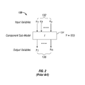
- Computational simulation models associated with a particular process can be constructed utilizing a mathematical sub-model representing each of the physical components.
- Each sub-model generally possesses a number of input variables and generates respective output variables as is shown schematically in the graphical diagram 130 shown in FIG. 2 .
- output variables 136 e.g., y1....yn
- output variables 136 e.g., y1....yn
- FIG. 3 illustrates a high-level flow chart of operations of a prior art method 300 for configuring engine models.
- a process layout such as the layouts/configurations shown in FIG. 1(a) or FIG. 1(b) can be utilized as a starting point of the procedure.
- a user can select required component sub-models from a component library.
- a user manually assigns all input variables with output variables from other component sub-models.
- a user manually introduces overall model readouts and assigns them with specific output variables. Performing all these steps results in a configured simulation model as indicated at block 310.
- Simulation models are generally implemented using graphical modeling tools or in lines of code.
- the input and output variable assignment as indicated in block 306 in FIG. 3 , as well as the creation of overall model readouts, as depicted at block 308 of FIG. 3 , can be carried out by creating graphical connections or using some form of pointers/tags.
- the difficulty in such an approach is that such operations currently must be performed manually.
- Such a manual assignment of input/output variables and the creation of overall model readouts is labor-intensive, cumbersome, and error prone, even for models with low complexity. Additionally, faults can be easily introduced during the configuration process, resulting in the simulation model to crash or produce incorrect results.
- a method and system for configuring a model of a process includes providing a model of a process that follows a particular sequence.
- a model includes a plurality of component sub-models, wherein each component sub-model among the component sub-models includes one or more input variables and one or more output variables.
- Such a method and system also generally include automatically assigning one or more input variables to one or more output variables based on information associated with the particular sequence of the process.
- a category and a search direction can be defined with respect to one or more of the input variables.
- the category can also be defined with respect to one or more of the output variables.
- a reference parameter can also be provided to connect one or more of the input variables to one or more of the output variables.
- each component sub-model can be configured to include one or more of the input variables and one or more of the output variables.
- Each component sub-model can also be embedded in a component block with one or more inport connectors and one or more outport connectors. Such inport and outport connectors generally connect the component block in the particular sequence of the process.
- one or more of the output variables can be assigned to the one or more of the input variables closest within the particular sequence of the process to one or more of the input variables in the search direction and which contains the same category as the input variable(s). This connection of output to input variables is carried out by assigning the reference parameter of the output variable to the input variable.
- An overall model readout can be automatically created by placing a readout block at a desired location in the particular sequence of the process and selecting a category of a readout signal to be readout. Also, relative to the readout block within the particular sequence of the process, the closest output variable which has the same category as that of the selected readout signal can be assigned to the overall model readout utilizing a connecting reference parameter.
- FIG. 4 illustrates a high-level flow chart of operations of an improved method 400 for configuring process models, in accordance with the disclosed embodiments.
- a process layout such as, for example, the layouts/configurations depicted in FIGS. 1(a) or 1(b) can be used as a starting point of the procedure.
- a user selects one or more required component blocks from a component library.
- a user can manually connect the component blocks in sequence of the process (i.e., according to the process layout).
- an automatic model configuration tool can be executed, which assigns all input variables with output variables and generates over model readouts. Performing all these steps can result in a configured simulation model, as indicated at block 418.
- the steps indicated at blocks 414 and 416 are very different from those of in prior art approaches such as, for example, the approach of the method 300 of FIG. 3 . While the method 300 depicted in FIG. 3 is manual, labor-intensive, and error prone, the method 400 is systematic, efficient, automated, and error free. In the prior art such as that depicted in FIG. 3 , the user selected component sub-models from a component library and then manually configured the input/output variables. The outputs of the model were also created manually via the approach described earlier with respect to FIG. 3 . With the methodology shown in FIG.
- the method 400 is automatic, efficient, and error free.
- FIG. 5 illustrates a block diagram depicting the format of an example component block 500, in accordance with the disclosed embodiments.
- the component block 500 generally includes an inport connector 510 and an outport connector 514.
- the component block 500 further includes a component sub-model 504, which is analogous to, for example, the component sub-model 134 shown in FIG. 2 .
- Input variables 506 and 508 can be provided to the component sub-model 504, which in turn produces an output variable 512.
- the number of input and output variables depends on the type of component (e.g. compressor, valve, etc).
- Each input variable such as, for example, input variables 506, 508, etc., can be assigned to or associated with a category (e.g., temperature, pressure, etc.) and a search direction (e.g., upstream or downstream of the process path), and a particular field can be provided to assign a connecting reference parameter (e.g., "ref par" in FIG. 5 ), which is shown as an empty field with respect to input variables 506 and 508.
- Every output variable such as, for example, output variable 512 shown in FIG. 5 is assigned to or associated with a category (e.g., temperature, pressure, etc.) and a unique connecting reference parameter such as, for example, "xyz" shown in FIG. 5 .
- Each component sub-model such as, for example, component sub-model 504 and its input variables 506, 508, etc. and output variable(s) 512 are embedded in the component block 500 with the inport connector 510 and the outport connector 514.
- FIG. 5 the structure depicted in FIG. 5 is predefined in the component library and requires no user interaction.
- the structural definition i.e. number of input and output variables and their categories etc.
- the user can then simply select predefined component blocks from the library and connects such predefined components in the sequence of the process through inport and outport connectors such as, for example inport connector 510 and outport connector 514.
- FIG. 6 depicts a diagram of a software topology 600, which allows for the automatic input and output assignments and the creation of readout signals, in accordance with the disclosed embodiments.
- the diagram depicted in FIG. 6 illustrates the structural preparations necessary so that the automated procedure described herein can be executed.
- the diagram of the software topology 600 depicts an excerpt of an example process model with three connected component blocks 602, 604, and 606 and a readout block 605. Note that blocks 602, 604, and 606 shown in FIG. 6 are generally analogous or similar to the component block 500 shown in FIG. 5 .
- component block 602 includes input variables 611 and 613 to component sub-model 603. An output variable 615 output from component sub-model 603 is also shown in FIG.
- Component block 604 includes input variables 617 and 619 to component sub-model 609 and output variables 621 and 623 thereof. That is, output variables 621 and 623 are shown in FIG. 6 just to the right of the component sub-model 609 and hence, are output from the component sub-model 609.
- component block 606 includes input variables 625 and 627 to component sub-model 607 and output variable 629 thereof.
- the component block 602 contains the component sub-model 603 with an input variable 611 of the category "pressure” and search direction "downstream".
- the connecting reference parameter of the input variable 611 is not assigned and hence empty at the start of the input/output assignment.
- the algorithm automatically searches in the specified search direction (e.g. downstream for input variable 611) along the process path for an output variable of a matching category as the current input variable.
- the downstream search reaches component block 604 containing component sub-model 609 with output variable 621, which matches the category of input variable 611 (i.e. "pressure”).
- the input and output variables are "connected” by assigning the unique connecting reference parameters of the output variable to the input variable.
- the connecting reference parameter "xxx" of output variable 621 is assigned.
- the input variables 625 and 627 of component block 606 can be assigned with reference parameters.
- the search direction is upstream of the process path and input variable 625 is assigned with output variable 621 while input variable 627 and output variable 615 are connected.
- the overall model readouts 608 can be specified by placing readout blocks such as the readout block 605 at particular locations in the process flow, where the user requires the model to provide readouts of certain process variables.
- the readout block 605 includes boxes such as boxes 631, 633 and 635, which can be "checked” in order to set the readout of a process variable active by selecting a particular category.
- the category associated with the box 631 is "pressure”
- the category associated with box 633 is "temperature”.
- the category of "pressure” is shown as selected via the "checked" box 631.
- Readout block 605 also displays several fields 637, 639, and 641, which for every active readout signal contains the connecting reference parameter of corresponding output variables. These fields are initially empty.
- the category For each active readout signal, the category is read. Note that in contrast to the automatic input/output assignment, the search direction where the matching output variable is located is not "a priori" known for the readout signals and is set to upstream per default. Similar to the input and output variable assignment, the disclosed approach automatically implements searching in this specified search direction along the process path for an output variable of the matching category as the readout signal. Once the output variable is found, its connecting reference parameter is read and an overall model readout is created to which this reference parameter is assigned. Once all active readout signals have been processed subsequently to having executed the input/output variable assignment, the model configuration is complete.
- the readout signal with category "pressure” is set active by checked box 631.
- the search direction is upstream by default, the search reaches block component 604 containing component sub-model 609 with output variable 621.
- Output variable 621 matches the category of the active readout signal and hence its reference parameter "xxx" is assigned to the readout signal in box 637. Additionally, the overall model readout 608 is created and the reference parameter "xxx" is assigned.
- the default search direction (e.g., upstream) may need to be reversed (e.g., set to downstream) in case it is determined that the required output variable is located downstream of the readout block such as readout block 605. (Note that the search direction is only reversed to downstream once and never back again (which is the default)).
- the upstream search for example, arrives at a component block, which has an input variable that is assigned to the downstream output variable with the identical category as the readout signal.
- FIG. 7 illustrates a high-level flow chart of operations illustrating logical operational steps of a method 700 for the automatic assignment of output variables to input variables, in accordance with the disclosed embodiments.
- a process model can be loaded to determine all input and output variables and the process sequence of the component blocks.
- a loop over all input variables is initiated by selecting the next input variable.
- an operation can be implemented to get the category and search direction of the current input variable.
- the starting point of the search can be defined to be the component block to which the input variable belongs.
- an operation can be implemented to determine the next component block along the specified direction of the process path.
- all output variables of the current component block are returned.
- a test can be implemented to determine if the current component block has an output variable with the matching category as the current input variable. If the answer is "no", then the operations shown at block 710 and 712 are repeated and so on. If the answer is "yes”, then as illustrated at block 716, the unique reference parameter of the matching output variable can be assigned to the current input variable in order to connect the two variables. Then, as indicated at block 718, a test can be performed to determine if all input variables have been processed.
- block 720 also refers to the corresponding flow chart shown in FIG. 8 with respect to determining all readout signals and assigning overall model readouts.
- FIG. 8 illustrates a high-level flow chart of operations depicting logical operational steps of a method 800 for creating overall model readouts based on active readout signals specified by a user, in accordance with the disclosed embodiments.
- an operation can be processed to determine all active readout signals in the loaded process model.
- a loop over all active readout signals can be initiated by selecting the next active readout signal.
- an operation can be implemented to get or retrieve the category of the active readout signal.
- an operation can be processed to define the starting point of search to be the readout block to which the active signal belongs.
- an operation can be implemented to define the search direction to be "upstream" by default.
- an operation can be implemented to determine the next component block along the specified direction of the process path. Thereafter, as illustrated at block 814, an operation can be implemented to return all output variables of the current component block. Then, as described at block 816, a test can be performed to determine if the search direction is upstream. If the answer is "yes”, then the operation indicated at block 817 is implemented. If the answer is "no", then the operation depicted at block 818 can be implemented.
- the operation illustrated at block 817 involves determining if the current component block has an input variable assigned to a downstream output variable with the identical category as the readout signal. If the answer is "yes”, then the operation indicated at block 819 can be implemented. If the answer is "no”, then the operation depicted at block 818 is processed. As indicated at block 819, once the required variable comes from the downstream direction, the search direction is set to "downstream” and the current component is reset to an initial starting point (i.e., original readout block).
- the operation described at block 818 involves determining if the current component block has an output variable with an identical category as the readout signal. Assuming the answer is "no”, then the operation indicated at block 812 is processed. Assuming the answer is "yes”, then as depicted at block 820, an operation can be processed to get the connecting reference parameter of the matching output variable. Thereafter, as illustrated at block 824, the overall model readout for the active readout signal can be created and the matching reference parameter assigned to it. Then, as depicted at block 826, a test can be performed to determine if all active readout signals have been processed. If the answer is "no", then the loop over all active readout signals continues with operations beginning at block 804, 806, etc. If the answer is "yes”, then as illustrated at block 828, the model configuration is completed.
- FIGS. 9-10 are provided as exemplary diagrams of data-processing environments in which embodiments of the present invention may be implemented. It should be appreciated that FIGS. 9-10 are only exemplary and are not intended to assert or imply any limitation with regard to the environments in which aspects or embodiments of the disclosed embodiments may be implemented. Many modifications to the depicted environments may be made without departing from the spirit and scope of the disclosed embodiments.
- a data-processing system 900 that includes, for example, a central processor 901, a main memory 912, an input/output controller 903, a keyboard 902, an input device 905 (e.g., a pointing device such as a mouse, track ball, pen device, etc), a display device 906, a mass storage 907 (e.g., a hard disk), and a USB (Universal Serial Bus) peripheral connection 911.
- a rendering device 908 e.g., printer, scanner, fax machine, etc
- a rendering device 908 may be associated with the data-processing system 900 as desired.
- the various components of data-processing system 900 can communicate electronically through a system bus 910 or similar architecture.
- the system bus 910 may be, for example, a subsystem that transfers data between, for example, computer components within data-processing system 900 or to and from other data-processing devices, components, computers, etc.
- FIG. 10 illustrates a computer software system 950 for directing the operation of the data-processing system 900 depicted in FIG. 9 .
- Software application 954 stored in main memory 912 and on mass storage 907, generally includes a kernel or operating system 951 and a shell or interface 953.
- One or more application programs, such as software application 954 may be "loaded” (i.e., transferred from mass storage 907 into the main memory 912) for execution by the data-processing system 900.
- the data-processing system 900 receives user commands and data through user interface 953; these inputs may then be acted upon by the data-processing system 900 in accordance with instructions from operating system module 951 and/or software application 954.
- program modules include, but are not limited to, routines, subroutines, software applications, programs, objects, components, data structures, etc., that perform particular tasks or implement particular abstract data types and instructions.
- program modules include, but are not limited to, routines, subroutines, software applications, programs, objects, components, data structures, etc., that perform particular tasks or implement particular abstract data types and instructions.
- program modules include, but are not limited to, routines, subroutines, software applications, programs, objects, components, data structures, etc., that perform particular tasks or implement particular abstract data types and instructions.
- program modules include, but are not limited to, routines, subroutines, software applications, programs, objects, components, data structures, etc., that perform particular tasks or implement particular abstract data types and instructions.
- program modules include, but are not limited to, routines, subroutines, software applications, programs, objects, components, data structures, etc., that perform particular tasks or implement particular abstract data types and instructions.
- program modules include, but are not limited to, routines, sub
- module may refer to a collection of routines and data structures that perform a particular task or implements a particular abstract data type. Modules may be composed of two parts: an interface, which lists the constants, data types, variable, and routines that can be accessed by other modules or routines; and an implementation, which is typically private (accessible only to that module) and which includes source code that actually implements the routines in the module.
- the term module may also simply refer to an application such as a computer program designed to assist in the performance of a specific task such as word processing, accounting, inventory management, etc.
- the interface 953, which is preferably a graphical user interface (GUI), can serve to display results, whereupon a user may supply additional inputs or terminate a particular session.
- operating system 951 and interface 953 can be implemented in the context of a "Windows" system such as that offered via a Mac personal computer or a Microsoft Windows environment. It can be appreciated, of course, that other types of operating systems and interfaces may be alternatively utilized. For example, rather than a traditional "Windows" system, other operation systems such as, for example, Linux may also be employed with respect to operating system 951 and interface 953.
- the software application 954 can include, for example, a simulation model generation module 952 for configuring a simulation model with respect to a particular process and/or system. Simulation model generation module 952 can include instructions, for example, such as those of methods 400, 700 and 800 discussed herein with respect to FIGS 4 , 7 , and 8 .
- programs defining functions with respect to the disclosed embodiments may be delivered to a data storage system or a computer system via a variety of signal-bearing media, which include, without limitation, non-writable storage media (e.g., CD-ROM), writable storage media (e.g., hard disk drive, read/write CD ROM, optical media), system memory such as, but not limited to, Random Access Memory (RAM), and communication media such as computer and telephone networks including, for example, Ethernet, the Internet, wireless networks, other networked systems.
- non-writable storage media e.g., CD-ROM
- writable storage media e.g., hard disk drive, read/write CD ROM, optical media
- system memory such as, but not limited to, Random Access Memory (RAM)
- RAM Random Access Memory
- communication media such as computer and telephone networks including, for example, Ethernet, the Internet, wireless networks, other networked systems.
Landscapes
- Engineering & Computer Science (AREA)
- Physics & Mathematics (AREA)
- Theoretical Computer Science (AREA)
- Computer Hardware Design (AREA)
- Evolutionary Computation (AREA)
- Geometry (AREA)
- General Engineering & Computer Science (AREA)
- General Physics & Mathematics (AREA)
- Stored Programmes (AREA)
- Testing And Monitoring For Control Systems (AREA)
- Feedback Control In General (AREA)
- Programmable Controllers (AREA)
Applications Claiming Priority (2)
| Application Number | Priority Date | Filing Date | Title |
|---|---|---|---|
| US36446610P | 2010-07-15 | 2010-07-15 | |
| US12/879,640 US8543362B2 (en) | 2010-07-15 | 2010-09-10 | System and method for configuring a simulation model utilizing a tool for automatic input/output assignment |
Publications (2)
| Publication Number | Publication Date |
|---|---|
| EP2407902A2 true EP2407902A2 (de) | 2012-01-18 |
| EP2407902A3 EP2407902A3 (de) | 2012-02-22 |
Family
ID=44533826
Family Applications (1)
| Application Number | Title | Priority Date | Filing Date |
|---|---|---|---|
| EP11172294A Ceased EP2407902A3 (de) | 2010-07-15 | 2011-06-30 | System und Verfahren zur Konfiguration eines Simulationsmodells mit einem Werkzeug zur automatischen Eingangs-/Ausgangszuordnung |
Country Status (2)
| Country | Link |
|---|---|
| US (1) | US8543362B2 (de) |
| EP (1) | EP2407902A3 (de) |
Cited By (2)
| Publication number | Priority date | Publication date | Assignee | Title |
|---|---|---|---|---|
| CN110855916A (zh) * | 2019-11-22 | 2020-02-28 | 中国电子科技集团公司第四十四研究所 | 一种输出通道数可变的模拟信号读出电路阵列及读取方法 |
| GB2616058A (en) * | 2022-02-25 | 2023-08-30 | Arrival Ltd | Computer-Implemented Methods of Executable workflow Generation |
Families Citing this family (6)
| Publication number | Priority date | Publication date | Assignee | Title |
|---|---|---|---|---|
| US9677493B2 (en) | 2011-09-19 | 2017-06-13 | Honeywell Spol, S.R.O. | Coordinated engine and emissions control system |
| US9650934B2 (en) | 2011-11-04 | 2017-05-16 | Honeywell spol.s.r.o. | Engine and aftertreatment optimization system |
| US10002164B2 (en) * | 2012-06-01 | 2018-06-19 | Ansys, Inc. | Systems and methods for context based search of simulation objects |
| US9146545B2 (en) | 2012-11-27 | 2015-09-29 | Honeywell International Inc. | Multivariable control system for setpoint design |
| EP3051367B1 (de) | 2015-01-28 | 2020-11-25 | Honeywell spol s.r.o. | Ansatz und system zur handhabung von einschränkungen für gemessene störungen mit unsicherer vorschau |
| US10415492B2 (en) | 2016-01-29 | 2019-09-17 | Garrett Transportation I Inc. | Engine system with inferential sensor |
Citations (1)
| Publication number | Priority date | Publication date | Assignee | Title |
|---|---|---|---|---|
| US9442702B1 (en) * | 2012-04-30 | 2016-09-13 | The Mathworks, Inc. | Overriding an interface in a graphical block diagram modeling environment |
Family Cites Families (14)
| Publication number | Priority date | Publication date | Assignee | Title |
|---|---|---|---|---|
| US7337102B2 (en) | 2003-12-29 | 2008-02-26 | The Mathworks, Inc. | Hierarchical references or links in modeling environments |
| US7162404B2 (en) | 2003-04-28 | 2007-01-09 | International Business Machines Corporation | Method, system and program product for configuring a simulation model of a digital design |
| US7530052B2 (en) | 2004-05-14 | 2009-05-05 | National Instruments Corporation | Creating and executing a graphical program with first model of computation that includes a structure supporting second model of computation |
| US7925477B2 (en) | 2004-09-20 | 2011-04-12 | The Mathworks, Inc. | Method and system for transferring data between a discrete event environment and an external environment |
| US7797674B1 (en) * | 2004-12-28 | 2010-09-14 | The Mathworks, Inc. | Independent component-wide parameter specification for graphical languages |
| US7437277B2 (en) | 2005-08-11 | 2008-10-14 | International Business Machines Corporation | Model independent simulation |
| US20070288885A1 (en) | 2006-05-17 | 2007-12-13 | The Mathworks, Inc. | Action languages for unified modeling language model |
| US8046202B1 (en) * | 2006-07-17 | 2011-10-25 | The Mathworks, Inc. | Generation of intermediate representations based on user specified elements in a graphical model that enable simulation, propagation and code generation |
| US7975233B2 (en) * | 2006-07-24 | 2011-07-05 | National Instruments Corporation | Automatic conversion of a textual language into a graphical program representation |
| US8108784B2 (en) * | 2006-08-04 | 2012-01-31 | National Instruments Corporation | Configuring icons to represent data transfer functionality |
| US8028242B2 (en) * | 2006-08-04 | 2011-09-27 | National Instruments Corporation | Diagram with configurable wires |
| US7698668B2 (en) | 2006-10-10 | 2010-04-13 | Honeywell International Inc. | Automatic translation of simulink models into the input language of a model checker |
| US7996782B2 (en) * | 2007-06-08 | 2011-08-09 | National Instruments Corporation | Data transfer indicator icon in a diagram |
| US8161380B2 (en) * | 2008-06-26 | 2012-04-17 | International Business Machines Corporation | Pipeline optimization based on polymorphic schema knowledge |
-
2010
- 2010-09-10 US US12/879,640 patent/US8543362B2/en active Active
-
2011
- 2011-06-30 EP EP11172294A patent/EP2407902A3/de not_active Ceased
Patent Citations (1)
| Publication number | Priority date | Publication date | Assignee | Title |
|---|---|---|---|---|
| US9442702B1 (en) * | 2012-04-30 | 2016-09-13 | The Mathworks, Inc. | Overriding an interface in a graphical block diagram modeling environment |
Cited By (3)
| Publication number | Priority date | Publication date | Assignee | Title |
|---|---|---|---|---|
| CN110855916A (zh) * | 2019-11-22 | 2020-02-28 | 中国电子科技集团公司第四十四研究所 | 一种输出通道数可变的模拟信号读出电路阵列及读取方法 |
| CN110855916B (zh) * | 2019-11-22 | 2021-12-24 | 中国电子科技集团公司第四十四研究所 | 一种输出通道数可变的模拟信号读出电路阵列及读取方法 |
| GB2616058A (en) * | 2022-02-25 | 2023-08-30 | Arrival Ltd | Computer-Implemented Methods of Executable workflow Generation |
Also Published As
| Publication number | Publication date |
|---|---|
| EP2407902A3 (de) | 2012-02-22 |
| US8543362B2 (en) | 2013-09-24 |
| US20120016647A1 (en) | 2012-01-19 |
Similar Documents
| Publication | Publication Date | Title |
|---|---|---|
| US8543362B2 (en) | System and method for configuring a simulation model utilizing a tool for automatic input/output assignment | |
| RU2433470C1 (ru) | Система и способ поддержки проектирования изделий | |
| US11454188B2 (en) | Systems and methods for rescaling executable simulation models | |
| CA2768445C (en) | Process for development of monitoring tools | |
| CN117521183B (zh) | 基于低代码化航空发动机零维仿真方法、设备、介质和产品 | |
| WO2007001108A1 (en) | System for providing feature-oriented software product line engineering environment | |
| CN112597584B (zh) | 基于数字孪生的数字样机构建及模型转换方法及装置 | |
| WO2019103775A1 (en) | Method and apparatus for automated suggestion of additional sensors or inputs from equipment or systems | |
| CN116384319A (zh) | 电子元件的布局方法及装置 | |
| US7289937B2 (en) | Method and apparatus for machine vector loop extraction | |
| EP3608786B1 (de) | Systeme und verfahren zur anforderungskettenbildung und anwendungen davon | |
| JP5047144B2 (ja) | マップ作成支援装置およびその方法並びにプログラム | |
| EP4332816A1 (de) | Modellierungssystem für virtuelles 3d-modell | |
| Reed et al. | Towards an automated full-turbofan engine numerical simulation | |
| KR101672763B1 (ko) | 시뮬레이션 인터페이스 생성방법 및 실시간 시뮬레이션 장치 | |
| Sampath et al. | High fidelity system simulation of aerospace vehicles using NPSS | |
| Asefa | A Review of Automatic Generation of Test Cases from Use Case Specification | |
| US20070083280A1 (en) | Method and system for three dimensional work instructions for modification processes | |
| CN113806860A (zh) | 基于仿真的故障特征提取系统、方法、存储介质及设备 | |
| CN120874396B (zh) | 基于模型的动力系统故障模式及影响分析方法 | |
| JP2005352670A (ja) | シミュレーション装置及び検査装置 | |
| US20250307122A1 (en) | Method for Generating a Simulation Code to Test a Control Logic Code | |
| Kurtulus | Development of a Tool for Inverse Aerodynamic Design and Optimisation of Turbomachinery Aerofoils | |
| O'Connell et al. | Software Tools for Efficient Model-Based Design of Energy Optimized Aircraft | |
| Keuth et al. | Successful integration of a model based calibration methodology for non-standard corrections and protection functions |
Legal Events
| Date | Code | Title | Description |
|---|---|---|---|
| 17P | Request for examination filed |
Effective date: 20110630 |
|
| AK | Designated contracting states |
Kind code of ref document: A2 Designated state(s): AL AT BE BG CH CY CZ DE DK EE ES FI FR GB GR HR HU IE IS IT LI LT LU LV MC MK MT NL NO PL PT RO RS SE SI SK SM TR |
|
| AX | Request for extension of the european patent |
Extension state: BA ME |
|
| PUAI | Public reference made under article 153(3) epc to a published international application that has entered the european phase |
Free format text: ORIGINAL CODE: 0009012 |
|
| PUAL | Search report despatched |
Free format text: ORIGINAL CODE: 0009013 |
|
| RIC1 | Information provided on ipc code assigned before grant |
Ipc: G06F 17/50 20060101AFI20120102BHEP |
|
| AK | Designated contracting states |
Kind code of ref document: A3 Designated state(s): AL AT BE BG CH CY CZ DE DK EE ES FI FR GB GR HR HU IE IS IT LI LT LU LV MC MK MT NL NO PL PT RO RS SE SI SK SM TR |
|
| AX | Request for extension of the european patent |
Extension state: BA ME |
|
| RIC1 | Information provided on ipc code assigned before grant |
Ipc: G06F 17/50 20060101AFI20120113BHEP |
|
| 17Q | First examination report despatched |
Effective date: 20120215 |
|
| RAP1 | Party data changed (applicant data changed or rights of an application transferred) |
Owner name: HONEYWELL INTERNATIONAL INC. |
|
| STAA | Information on the status of an ep patent application or granted ep patent |
Free format text: STATUS: THE APPLICATION HAS BEEN REFUSED |
|
| 18R | Application refused |
Effective date: 20180715 |