EP2407790B1 - Halter und analysegerät für einen reaktionsbehälter - Google Patents
Halter und analysegerät für einen reaktionsbehälter Download PDFInfo
- Publication number
- EP2407790B1 EP2407790B1 EP10750714.7A EP10750714A EP2407790B1 EP 2407790 B1 EP2407790 B1 EP 2407790B1 EP 10750714 A EP10750714 A EP 10750714A EP 2407790 B1 EP2407790 B1 EP 2407790B1
- Authority
- EP
- European Patent Office
- Prior art keywords
- reaction container
- retaining
- reaction
- level difference
- section
- Prior art date
- Legal status (The legal status is an assumption and is not a legal conclusion. Google has not performed a legal analysis and makes no representation as to the accuracy of the status listed.)
- Active
Links
Images

Classifications
-
- G—PHYSICS
- G01—MEASURING; TESTING
- G01N—INVESTIGATING OR ANALYSING MATERIALS BY DETERMINING THEIR CHEMICAL OR PHYSICAL PROPERTIES
- G01N35/00—Automatic analysis not limited to methods or materials provided for in any single one of groups G01N1/00 - G01N33/00; Handling materials therefor
- G01N35/02—Automatic analysis not limited to methods or materials provided for in any single one of groups G01N1/00 - G01N33/00; Handling materials therefor using a plurality of sample containers moved by a conveyor system past one or more treatment or analysis stations
- G01N35/025—Automatic analysis not limited to methods or materials provided for in any single one of groups G01N1/00 - G01N33/00; Handling materials therefor using a plurality of sample containers moved by a conveyor system past one or more treatment or analysis stations having a carousel or turntable for reaction cells or cuvettes
-
- B—PERFORMING OPERATIONS; TRANSPORTING
- B01—PHYSICAL OR CHEMICAL PROCESSES OR APPARATUS IN GENERAL
- B01L—CHEMICAL OR PHYSICAL LABORATORY APPARATUS FOR GENERAL USE
- B01L7/00—Heating or cooling apparatus; Heat insulating devices
-
- B—PERFORMING OPERATIONS; TRANSPORTING
- B01—PHYSICAL OR CHEMICAL PROCESSES OR APPARATUS IN GENERAL
- B01L—CHEMICAL OR PHYSICAL LABORATORY APPARATUS FOR GENERAL USE
- B01L9/00—Supporting devices; Holding devices
-
- B—PERFORMING OPERATIONS; TRANSPORTING
- B01—PHYSICAL OR CHEMICAL PROCESSES OR APPARATUS IN GENERAL
- B01L—CHEMICAL OR PHYSICAL LABORATORY APPARATUS FOR GENERAL USE
- B01L2300/00—Additional constructional details
- B01L2300/18—Means for temperature control
- B01L2300/1805—Conductive heating, heat from thermostatted solids is conducted to receptacles, e.g. heating plates, blocks
- B01L2300/1827—Conductive heating, heat from thermostatted solids is conducted to receptacles, e.g. heating plates, blocks using resistive heater
-
- G—PHYSICS
- G01—MEASURING; TESTING
- G01N—INVESTIGATING OR ANALYSING MATERIALS BY DETERMINING THEIR CHEMICAL OR PHYSICAL PROPERTIES
- G01N35/00—Automatic analysis not limited to methods or materials provided for in any single one of groups G01N1/00 - G01N33/00; Handling materials therefor
- G01N2035/00346—Heating or cooling arrangements
- G01N2035/00356—Holding samples at elevated temperature (incubation)
Definitions
- the present invention relates to: a reaction container holder for keeping a plurality of reaction containers at a constant temperature, each reaction container housing a reaction liquid of a reagent and a specimen; and an analyzer comprising the reaction container holder.
- analyzers analyze a specimen by optically measuring a reaction liquid obtained by reaction between a specimen and a reagent while keeping the reaction liquid at a temperature as high as a human's body temperature .
- the analyzers include a reaction container holder which rotates while keeping a plurality of reaction containers for housing a reaction liquid at a constant temperature (see Patent Literature 1, for example) .
- a reaction container holder it is known to include a retaining member having a plurality of retaining sections for retaining reaction containers, and a circular rotating member for detachably fixing the retaining member from above and rotating, where the retaining member can be removed from the rotating member for the cleaning of the retaining member.
- Patent Literature 1 Japanese Laid-Open Publication No. 2008-58250
- US 6 562 298 B1 relates to a structure for a determination of an item of interest in a sample.
- US 6 562 298 B1 discloses reagent containers that are directly engaged with a reagent carousel.
- the reagent carousel may be maintained within a thermostatically controlled environment.
- EP 0 353 592 A2 discloses a semi-automated biological sample analyzer and subsystems to simultaneously perform a plurality of enzyme immuno assays for human IgE class antibodies specific to a panel of preselected allergens in each of a plurality of biological samples.
- a carousel is provided to position and hold a plurality of reaction cartridges.
- the carousel and cartridges contain structures which cooperate to precisely position the cartridges in each of three separate dimensions so that each cartridge is positioned uniformly.
- US 4 056361 A discloses a carrier and a vial or other container, the carrier having a container locating pocket, in which the container is located, with an upwardly opening inlet through which the container can be lowered into the pocket in any position of angular displacement about the container axis, the container having a plane, bottom cam surface which interacts with a complementary cam surface of the pocket, when the container is lowered into the pocket, in such manner that said container when fully home in the pocket occupies a predetermined position of angular displacement about the container axis.
- US 2004/265173 A1 discloses an automated analyzer for analyzing a specific component in a specimen.
- the analyzer includes a rotor, a specimen dispenser, a temperature controlling element, a stirrer, and a data analyzer.
- the rotor is provided with a plurality of specimen container holders for holding the specimen container containing the specimen, and a plurality of reaction container holders that correspond with each of the specimen container holders and hold the sealed reaction containers containing the reagent for reacting with the specimen.
- the specimen dispenser removes the specimen from the specimen container and dispenses the specimen into the reaction container.
- a temperature controlling element maintains the temperatures of the reaction container at a constant temperature.
- the stirrer uses magnetic force to stir a mixed solution of the reagent and the specimen in the reaction container.
- the data analyzer analyzes the mixed solution.
- the present invention is intended to solve such a problem as described above. It is an objective of the present invention to provide: a reaction container holder capable of inhibiting the lowering of the transfer efficiency of the heat transferred from the rotating member to the bottom surface of the reaction container; and an analyzer comprising the reaction container holder.
- reaction container holder according to claim 1.
- Preferred embodiments are subject of the dependent claims.
- the level difference section is a convex portion formed at the outer edge of the rotating member along the circumferential direction, and engages with the retaining section when the retaining member is fixed to the rotating member.
- the level difference section is formed in a trapezoidal pyramid, or a trapezoidal cone, with a narrowing upper part.
- the retaining section comprises a protruding piece, which is a downward protrusion of a side wall on an outer periphery side thereof, and the protruding piece fits tightly with the level difference section when the retaining member is fixed to the rotating member.
- the level difference section comprises an elastic heat transferring material coated on an upper surface of the level difference thereof.
- An analyzer according to the present invention for measuring optical properties of a reaction liquid of a reagent and a specimen housed in the reaction container, to analyze the reaction liquid is characterized in that the analyzer optically analyzes the reaction liquid by using the reaction container holder according to the present invention, thereby solving the problem and achieving the objective as described above.
- the gap produced between the bottom part of the reaction container and the rotating member can be reduced, thereby inhibiting the lowering of the transfer efficiency of the heat transferred from the rotating member to the bottom surface of the reaction container.
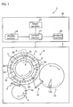
- FIG 1 is a schematic view illustrating a configuration of an analyzer according to the Embodiments of the present invention.
- An analyzer 1 according to the Embodiments includes a measuring section 2 and a control apparatus 20.
- the measuring section 2 dispenses each of a specimen and a reagent into a reaction container 7, and optically measures a reaction caused in the reaction container 7.
- the control apparatus 20 performs the overall control of the analyzer 1 including the measuring section 2, and analyzes a measurement result in the measuring section 2.
- the measuring section 2 includes a specimen table 4, a specimen dispensing mechanism 5, a reaction container holder 6, a stirring apparatus 10, a photometry apparatus 11, a washing apparatus 12, a reagent table 13 and a reagent dispensing mechanism 14.
- the specimen table 4 is rotated in the direction of the arrow by a driving means (not shown), and a specimen container 4a having a specimen housed therein is detachably stored in the specimen table 4.
- the specimen dispensing mechanism 5 is a means for dispensing a specimen into a plurality of reaction containers 7 retained in the reaction container holder 6, and the specimen dispensing mechanism 5 dispenses a specimen from a plurality of specimen containers 4a of the specimen table 4 successively into the reaction containers 7.
- the reaction container holder 6 is rotated in the direction of the arrow by a driving means (not shown), and the reaction container holder 6 retains and keeps a plurality of reaction containers 7 at a constant temperature to keep a liquid sample, containing a reagent and a sample, dispensed into the reaction containers 7 at a constant temperature.
- the reaction container holder 6 includes a retaining member 8 and a rotating member 9.
- the retaining member 8 consists of a plurality of retaining member units 8A, each retaining member unit 8A being detachably fixed along the circumferential direction of the rotating member 9 by a screw 6a.
- the retaining member unit 8A includes a plurality of container retaining sections 8b for retaining the reaction containers 7 of a substantially rectangular parallelepiped shape.
- the rotating member 9 is a circular member which is rotated by a driving mechanism (not shown), with a vertical line along the center of the reaction container holder 6 as an axis of rotation.
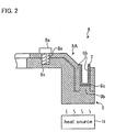
- the rotating member 9 includes a level difference section 9b, as illustrated in Figure 2 .
- the level difference section 9b is a convex portion of a substantially rectangular parallelepiped shape formed at the outer edge of the rotating member 9 along the circumferential direction.
- an upper surface 9c of the level difference section 9b when the retaining member unit 8A is fixed, the upper surface 9c of a level difference is positioned within the container retaining section 8b and above the bottom part of the container retaining section 8b.
- a heat source H is provided below the rotating member 9. Heat generated from the heat source H is transferred to the reaction container 7 through the rotating member 9.
- the stirring apparatus 10 stirs a liquid sample containing a reagent and a specimen housed in a reaction container 7.
- the photometry apparatus 11 includes a light source for emitting analysis light, the analysis light being for analyzing a reaction liquid obtained by reaction between a specimen and a reagent housed in a reaction container 7, and a light receiver for separating and receiving the analysis light, which is transmitted through the reaction liquid.
- the photometry apparatus 11 measures optical properties of the reaction liquid in the reaction container 7 and outputs a measurement result thereof to the control apparatus 20.
- the washing apparatus 12 washes inside the reaction container 7 which has finished the measurement performed by the photometry apparatus 11.
- the reagent table 13 is rotated in the direction of the arrow by a driving means (not shown), and a reagent container 13a housing a reagent is detachably stored therein.
- the reagent dispensing mechanism 14 is a means for dispensing a reagent into a plurality of reaction containers 7 retained by the reaction container holder 6, and the reagent dispensing mechanism 14 dispenses a reagent from a given reagent container 13a of the reagent table 13 successively into reaction containers 7.
- the control apparatus 20 includes a control section 21, an analysis section 22, an input section 23 and a display section 24.
- the control section 21 is connected with the measuring section 2 and the respective sections described above within the control apparatus 20, and is effectuated by a microcomputer or the like.
- the control section 21 controls the operation of respective sections of the analyzer 1.
- the analysis section 22 analyzes concentration of components of a specimen or the like on the basis of optical properties of a reaction liquid in a reaction container 7 measured by the photometry apparatus 11, and outputs an analysis result to the control section 21.
- the input section 23 is an operation section for performing operations of inputting an examination menu to the control section 21.
- the input section 23 is effectuated by a keyboard, a mouse or the like.
- the display section 24 displays analysis content, analysis results, warning or the like, and the display section 24 is effectuated by a display panel or the like.
- the reagent dispensing mechanism 14 successively dispenses a reagent from the reagent container 13a into the plurality of reaction containers 7 transported along the circumferential direction by the rotating reaction container holder 6.
- the reaction containers 7 with the dispensed reagent therein are transported by the reaction container holder 6 along the circumferential direction thereof, and the reaction containers 7 are successively dispensed with a specimen by the specimen dispensing mechanism 5 from a plurality of specimen containers 4a retained to the specimen table 4.
- the reaction containers 7 with the specimen dispensed therein are conveyed to the stirring apparatus 10 by the reaction container holder 6, and the dispensed reagent and specimen are successively stirred and they react with each other.
- the analysis light that has transmitted the reaction liquid is measured with regard to optical properties, and concentration of the components or the like is analyzed by the analysis section 22.
- the reaction containers 7 which have finished with the analysis are washed by the washing apparatus 12.
- the analyzer 1 successively performs such a series of analysis operations .
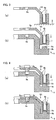
- the operator inserts reaction containers 7 into each of a plurality of container retaining sections 8b, allowing the retaining member units 8A to be upright on a flat working plane S, such as a desk.
- the reaction containers 7 are retained by the retaining member unit 8A in such a manner that the bottom surfaces of the reaction containers 7 are positioned near the bottom part of the container retaining sections 8b (see Figure 3(a) ).
- the reaction containers 7 may also be retained such that the bottom surfaces of the reaction containers 7 are retained at a position above the bottom part of the container retaining sections 8b, as illustrated in Figure 3(a) .
- the retaining member unit 8A is assembled into the rotating member 9 from above such that the container retaining section 8b is engaged with the level difference section 9b (see Figure 3(b) ).
- the operator begins to screw the screw 6a tight.
- the retaining member unit 8A begins to descend towards a position where the retaining member unit 8A is to be fixed with the rotating member 9, and during the descending, the upper surface 9c of the level difference section 9b touches the bottom surface of the reaction container 7 (see Figure 4(a) ).
- the level difference section 9b engages with the container retaining sections 8b such that the upper surface 9c is positioned above the bottom part of the container retaining sections 8b.
- the upper surface 9c of the level difference section 9b touches the bottom surface of the reaction container 7.
- the retaining member unit 8A descends while leaving the reaction container 7 on the upper surface 9c of the level difference section 9b.
- the retaining member unit 8A is fixed to the rotating member 9 (see Figure 4(b) ).
- the upper surface 9c of the level difference section 9b is positioned above the bottom part of the container retaining sections 8b within the container retaining sections 8b. Accordingly, even if the bottom surface of the reaction container 7 is retained at a position higher than the bottom part of the container retaining sections 8b, or even if the bottom part of the container retaining sections 8b is fixed at a position higher than a predetermined position with respect to the rotating member 9, the occurrence of the gap between the bottom part of the reaction container 7 and the rotating member 9 can be reduced. Therefore, the lowering of the transfer efficiency of the heat transferred from the rotating member 9 to the bottom surface of the reaction container 7 can be inhibited.
- the retaining member unit 8A is fixed to the rotating member 9 by engaging the container retaining sections 8b with the level difference section 9b, the retaining member 8 can be fixed at a correct position with respect to the rotating member 9.
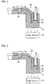
- the level difference section of the rotating member 9 is formed, for example, in a trapezoidal pyramid with a narrowing upper part, as the level difference section 9d illustrated in Figure 5 .
- the container retaining sections 8b and the level difference section 9d engage with each other by being guided by the inclined side surface of the level difference section 9d, making it possible to engage the container retaining sections 8b with the level difference section 9d with ease.
- the level difference section 9d may also be a trapezoidal cone with a narrowing upper part.
- the level difference section of the rotating member 9 is, for example, such that an upper surface 9h of a level difference section 9f is coated with an elastic heat transferring material 9g, as the level difference section 9f illustrated in Figure 6 .
- the heat transferring material 9g may also coat the upper surface 9h of the level difference section 9f, with an adhesive having heat conductivity.
- the heat transferring material 9g itself may also be adhered directly to the upper surface 9h of the level difference section 9f.
- the heat transferring material 9g is elastically deformed. As a result, the bottom surface of the reaction container 7 can be adhered to the level difference section 9f even better.
- a container retaining section 8b of a retaining member unit 8A includes a protruding piece 8e as illustrated in Figure 7 .
- the protruding piece 8e is a protruding portion of the lower part of a side wall 8d, which is the one closer to the outer periphery between the side walls 8c and 8d opposing with each other in a horizontal direction.
- the retaining member 8 is exemplified as consisting of a plurality of retaining member units 8A, the retaining member 8 may also be a single unit.
Landscapes
- Chemical & Material Sciences (AREA)
- Health & Medical Sciences (AREA)
- Chemical Kinetics & Catalysis (AREA)
- Clinical Laboratory Science (AREA)
- Analytical Chemistry (AREA)
- Life Sciences & Earth Sciences (AREA)
- Physics & Mathematics (AREA)
- Biochemistry (AREA)
- General Health & Medical Sciences (AREA)
- General Physics & Mathematics (AREA)
- Immunology (AREA)
- Pathology (AREA)
- Automatic Analysis And Handling Materials Therefor (AREA)
Claims (6)
- Ein Reaktionsbehälter-Halter (6), der Folgendes umfasst:ein Rückhalteelement (8), das eine Vielzahl von Rückhalteabschnitten (8b) zum Zurückhalten von Reaktionsbehältern (7) umfasst, wobei die Vielzahl von Rückhalteabschnitten (8b) vom Rückhalteelement (8) nicht entfernbar ist, wobei der Reaktionsbehälter (7) von den Rückhalteabschnitten (8b) getrennt ist und zur Aufnahme einer flüssigen Probe (sample) geeignet ist, die einen Reagens (reagent) und einen Prüfkörper (specimen) enthält; undein kreisförmiges rotierendes Element (9) zum lösbaren Befestigen des Halteelements (8) von oben und zum Drehen, wobeidas rotierende Element (9) einen Niveaudifferenzbereich (9b; 9d; 9f; 9i) umfasst, wobei eine obere Oberfläche des Niveaudifferenzbereichs (9b; 9d; 9f; 9i) über einem unteren Teil des Rückhalteabschnitts (8b) innerhalb des Rückhalteabschnitts (8b) positioniert ist, wenn das Rückhalteelement (8) befestigt ist, und wobei der Reaktionsbehälter-Halter (6) konfiguriert ist, um den Reaktionsbehälter (7) bei einer konstanten Temperatur zu halten, indem Wärme durch den Niveaudifferenzabschnitt (9b; 9d; 9f; 9i) des rotierenden Elements (9) zum Reaktionsbehälter (7) übertragen wird.
- Der Reaktionsbehälter-Halter (6) nach Anspruch 1, dadurch gekennzeichnet, dass der Niveaudifferenzabschnitt (9b; 9d; 9f; 9i) ein konvexer Abschnitt ist, der an der Außenkante des rotierenden Elements (9) entlang der Umfangsrichtung ausgebildet ist, und mit dem Halteabschnitt (8b) in Eingriff kommt, wenn das Rückhalteelement (8) am rotierenden Element (9) befestigt ist.
- Der Reaktionsbehälter-Halter (6) nach Anspruch 2, dadurch gekennzeichnet, dass der Niveaudifferenzabschnitt (9b; 9d; 9f; 9i) in einer trapezförmigen Pyramide oder einem trapezförmigen Kegel mit einem sich verengenden Oberteil ausgebildet ist.
- Der Reaktionsbehälter-Halter (6) nach Anspruch 1, dadurch gekennzeichnet, dass der Halteabschnitt (8b) ein vorstehendes Teil (8e) umfasst, das ein nach unten vorstehender Überstand einer Seitenwand auf einer Seite des äußeren Umfangs davon ist, und wobei das vorstehende Teil (8e) eng mit dem Niveaudifferenzabschnitt (9b; 9d; 9f; 9i) zusammenpasst, wenn das Halteelement (8) am rotierenden Element (9) befestigt ist.
- Der Reaktionsbehälter-Halter (6) nach irgendeinem der Ansprüche von 1 bis 4, dadurch gekennzeichnet, dass der Niveaudifferenzabschnitt (9b; 9d; 9f; 9i) ein elastisches wärmeübertragendes Material (9g) umfasst, das auf die Oberseite des Niveaudifferenzabschnitts (9b; 9d; 9f; 9i) aufgetragen ist.
- Ein Analysator (1) zum Messen von optischen Eigenschaften einer Reaktionsflüssigkeit eines Reagens und eines im Reaktionsbehälter (7) aufgenommenen Prüfkörpers, um die Reaktionsflüssigkeit zu analysieren, dadurch gekennzeichnet, dass der Analysator (1) den Reaktionsbehälter-Halter (6) nach irgendeinem der Ansprüche von 1 bis 5 umfasst und konfiguriert ist, um die Reaktionsflüssigkeit im Reaktionsbehälter-Halter (6) optisch zu analysieren.
Applications Claiming Priority (2)
| Application Number | Priority Date | Filing Date | Title |
|---|---|---|---|
| JP2009055559A JP5336889B2 (ja) | 2009-03-09 | 2009-03-09 | 反応容器ホルダおよび分析装置 |
| PCT/JP2010/053348 WO2010103960A1 (ja) | 2009-03-09 | 2010-03-02 | 反応容器ホルダおよび分析装置 |
Publications (3)
| Publication Number | Publication Date |
|---|---|
| EP2407790A1 EP2407790A1 (de) | 2012-01-18 |
| EP2407790A4 EP2407790A4 (de) | 2014-01-08 |
| EP2407790B1 true EP2407790B1 (de) | 2019-09-25 |
Family
ID=42728250
Family Applications (1)
| Application Number | Title | Priority Date | Filing Date |
|---|---|---|---|
| EP10750714.7A Active EP2407790B1 (de) | 2009-03-09 | 2010-03-02 | Halter und analysegerät für einen reaktionsbehälter |
Country Status (5)
| Country | Link |
|---|---|
| US (1) | US8496891B2 (de) |
| EP (1) | EP2407790B1 (de) |
| JP (1) | JP5336889B2 (de) |
| CN (1) | CN102341711B (de) |
| WO (1) | WO2010103960A1 (de) |
Cited By (1)
| Publication number | Priority date | Publication date | Assignee | Title |
|---|---|---|---|---|
| EP4163640A4 (de) * | 2020-06-08 | 2024-06-12 | Hitachi High-Tech Corporation | Automatische analysevorrichtung |
Families Citing this family (5)
| Publication number | Priority date | Publication date | Assignee | Title |
|---|---|---|---|---|
| JP5978039B2 (ja) * | 2012-07-24 | 2016-08-24 | 株式会社日立ハイテクノロジーズ | 自動分析装置 |
| AU2013202793B2 (en) * | 2012-07-31 | 2014-09-18 | Gen-Probe Incorporated | System, method and apparatus for automated incubation |
| PL126707U1 (pl) * | 2017-10-16 | 2019-04-23 | Kopec Dariusz | Blokada antykradzieżowa, zwłaszcza motocykla |
| CN108646043B (zh) * | 2018-07-25 | 2023-06-27 | 苏州长光华医生物医学工程有限公司 | 一种试剂瓶定位总成 |
| US12523673B2 (en) * | 2020-03-05 | 2026-01-13 | Hitachi High-Tech Corporation | Automatic analysis device |
Citations (2)
| Publication number | Priority date | Publication date | Assignee | Title |
|---|---|---|---|---|
| US4056361A (en) * | 1975-06-11 | 1977-11-01 | The Secretary Of State For Social Services In Her Britannic Majesty's Government Of The United Kingdom Of Great Britain And Northern Ireland | Vial or other container, and carrier therefor |
| US20040265173A1 (en) * | 2003-05-06 | 2004-12-30 | Tosoh Corporation | Automated analyzer |
Family Cites Families (12)
| Publication number | Priority date | Publication date | Assignee | Title |
|---|---|---|---|---|
| JPS58127360U (ja) * | 1982-02-24 | 1983-08-29 | オリンパス光学工業株式会社 | 恒温装置 |
| JPS60105967A (ja) * | 1983-11-15 | 1985-06-11 | Nippon Tectron Co Ltd | 自動分析装置における反応容器の保持構造 |
| JPS63208744A (ja) * | 1987-02-26 | 1988-08-30 | Toshiba Corp | 自動化学分析装置のドライ型恒温槽 |
| JPH01150858A (ja) * | 1987-12-08 | 1989-06-13 | Toshiba Corp | 自動化学分析装置のドライ恒温型反応槽 |
| US5320808A (en) * | 1988-08-02 | 1994-06-14 | Abbott Laboratories | Reaction cartridge and carousel for biological sample analyzer |
| JP2723922B2 (ja) * | 1988-09-07 | 1998-03-09 | 株式会社日立製作所 | 空気恒温槽を備えた自動分析装置 |
| US5856194A (en) * | 1996-09-19 | 1999-01-05 | Abbott Laboratories | Method for determination of item of interest in a sample |
| WO1999024160A1 (de) * | 1997-11-08 | 1999-05-20 | Chemspeed, Ltd. | Vorrichtung zur halterung von temperier- und schüttelbaren reaktionsgefässen |
| CN101449169A (zh) * | 2006-05-22 | 2009-06-03 | 奥林巴斯株式会社 | 分析装置 |
| GB2439527B (en) * | 2006-06-30 | 2009-05-27 | Asynt Ltd | Laboratory apparatus |
| JP2008058250A (ja) * | 2006-09-01 | 2008-03-13 | Olympus Corp | 分析装置 |
| JP2009042049A (ja) * | 2007-08-08 | 2009-02-26 | Olympus Corp | 自動分析装置 |
-
2009
- 2009-03-09 JP JP2009055559A patent/JP5336889B2/ja active Active
-
2010
- 2010-03-02 EP EP10750714.7A patent/EP2407790B1/de active Active
- 2010-03-02 WO PCT/JP2010/053348 patent/WO2010103960A1/ja not_active Ceased
- 2010-03-02 US US13/202,571 patent/US8496891B2/en active Active
- 2010-03-02 CN CN201080010782.7A patent/CN102341711B/zh active Active
Patent Citations (2)
| Publication number | Priority date | Publication date | Assignee | Title |
|---|---|---|---|---|
| US4056361A (en) * | 1975-06-11 | 1977-11-01 | The Secretary Of State For Social Services In Her Britannic Majesty's Government Of The United Kingdom Of Great Britain And Northern Ireland | Vial or other container, and carrier therefor |
| US20040265173A1 (en) * | 2003-05-06 | 2004-12-30 | Tosoh Corporation | Automated analyzer |
Cited By (1)
| Publication number | Priority date | Publication date | Assignee | Title |
|---|---|---|---|---|
| EP4163640A4 (de) * | 2020-06-08 | 2024-06-12 | Hitachi High-Tech Corporation | Automatische analysevorrichtung |
Also Published As
| Publication number | Publication date |
|---|---|
| CN102341711A (zh) | 2012-02-01 |
| CN102341711B (zh) | 2014-03-19 |
| JP5336889B2 (ja) | 2013-11-06 |
| EP2407790A4 (de) | 2014-01-08 |
| US20110311397A1 (en) | 2011-12-22 |
| JP2010210346A (ja) | 2010-09-24 |
| WO2010103960A1 (ja) | 2010-09-16 |
| EP2407790A1 (de) | 2012-01-18 |
| US8496891B2 (en) | 2013-07-30 |
Similar Documents
| Publication | Publication Date | Title |
|---|---|---|
| EP2407790B1 (de) | Halter und analysegerät für einen reaktionsbehälter | |
| US9329194B2 (en) | Automated analyzer for clinical laboratory | |
| EP0517092B1 (de) | Reagenzienpackung für Immunoassays | |
| US5145646A (en) | Reagent bottle and cap | |
| JP6170511B2 (ja) | 細胞を調製するためのシステム、装置及びデバイス | |
| US7959878B2 (en) | Unit cuvette for analyzing a biological fluid, automatic device for in vitro analysis | |
| CN103884851B (zh) | 用于管理散装液体和/或固体的系统 | |
| JP6120763B2 (ja) | 反応槽を搬送する装置およびプロセス | |
| EP3628402A1 (de) | Reagenzbehälterregal und probenanalysator | |
| JP6634222B2 (ja) | 体外診断分析方法およびシステム | |
| JP2019197052A (ja) | 試験試料に含有される干渉物質を分離するための検査室システムおよび方法 | |
| EP3745135A1 (de) | Probenmessvorrichtung und verfahren zum zirkulieren von luft bei der lagerung von reagenzien | |
| US8211313B2 (en) | System for processing magnetic particles | |
| US20200355713A1 (en) | Sample measuring apparatus, reagent container, and method of measuring sample | |
| KR20040097953A (ko) | 분석기와, 샘플 분석 방법과, 구성요소 이송 방법 및데스크탑형 분석기용 액체 이송 시스템 | |
| EP4471428A1 (de) | Automatische analysevorrichtung und automatisches analyseverfahren | |
| JP7233945B2 (ja) | 保管装置 | |
| CN107037225A (zh) | 容器收容支架及分析装置 | |
| US20240133688A1 (en) | Laboratory instrument | |
| JP5978039B2 (ja) | 自動分析装置 |
Legal Events
| Date | Code | Title | Description |
|---|---|---|---|
| PUAI | Public reference made under article 153(3) epc to a published international application that has entered the european phase |
Free format text: ORIGINAL CODE: 0009012 |
|
| 17P | Request for examination filed |
Effective date: 20110901 |
|
| AK | Designated contracting states |
Kind code of ref document: A1 Designated state(s): AT BE BG CH CY CZ DE DK EE ES FI FR GB GR HR HU IE IS IT LI LT LU LV MC MK MT NL NO PL PT RO SE SI SK SM TR |
|
| DAX | Request for extension of the european patent (deleted) | ||
| A4 | Supplementary search report drawn up and despatched |
Effective date: 20131205 |
|
| RIC1 | Information provided on ipc code assigned before grant |
Ipc: G01N 35/04 20060101AFI20131129BHEP Ipc: B01L 7/00 20060101ALI20131129BHEP Ipc: G01N 35/02 20060101ALI20131129BHEP Ipc: G01N 35/00 20060101ALI20131129BHEP Ipc: B01L 9/00 20060101ALI20131129BHEP |
|
| STAA | Information on the status of an ep patent application or granted ep patent |
Free format text: STATUS: EXAMINATION IS IN PROGRESS |
|
| 17Q | First examination report despatched |
Effective date: 20180725 |
|
| GRAP | Despatch of communication of intention to grant a patent |
Free format text: ORIGINAL CODE: EPIDOSNIGR1 |
|
| STAA | Information on the status of an ep patent application or granted ep patent |
Free format text: STATUS: GRANT OF PATENT IS INTENDED |
|
| INTG | Intention to grant announced |
Effective date: 20190503 |
|
| GRAS | Grant fee paid |
Free format text: ORIGINAL CODE: EPIDOSNIGR3 |
|
| GRAA | (expected) grant |
Free format text: ORIGINAL CODE: 0009210 |
|
| STAA | Information on the status of an ep patent application or granted ep patent |
Free format text: STATUS: THE PATENT HAS BEEN GRANTED |
|
| AK | Designated contracting states |
Kind code of ref document: B1 Designated state(s): AT BE BG CH CY CZ DE DK EE ES FI FR GB GR HR HU IE IS IT LI LT LU LV MC MK MT NL NO PL PT RO SE SI SK SM TR |
|
| REG | Reference to a national code |
Ref country code: GB Ref legal event code: FG4D |
|
| REG | Reference to a national code |
Ref country code: CH Ref legal event code: EP |
|
| REG | Reference to a national code |
Ref country code: DE Ref legal event code: R096 Ref document number: 602010061220 Country of ref document: DE |
|
| REG | Reference to a national code |
Ref country code: AT Ref legal event code: REF Ref document number: 1184321 Country of ref document: AT Kind code of ref document: T Effective date: 20191015 |
|
| REG | Reference to a national code |
Ref country code: IE Ref legal event code: FG4D |
|
| REG | Reference to a national code |
Ref country code: NL Ref legal event code: MP Effective date: 20190925 |
|
| PG25 | Lapsed in a contracting state [announced via postgrant information from national office to epo] |
Ref country code: HR Free format text: LAPSE BECAUSE OF FAILURE TO SUBMIT A TRANSLATION OF THE DESCRIPTION OR TO PAY THE FEE WITHIN THE PRESCRIBED TIME-LIMIT Effective date: 20190925 Ref country code: LT Free format text: LAPSE BECAUSE OF FAILURE TO SUBMIT A TRANSLATION OF THE DESCRIPTION OR TO PAY THE FEE WITHIN THE PRESCRIBED TIME-LIMIT Effective date: 20190925 Ref country code: SE Free format text: LAPSE BECAUSE OF FAILURE TO SUBMIT A TRANSLATION OF THE DESCRIPTION OR TO PAY THE FEE WITHIN THE PRESCRIBED TIME-LIMIT Effective date: 20190925 Ref country code: BG Free format text: LAPSE BECAUSE OF FAILURE TO SUBMIT A TRANSLATION OF THE DESCRIPTION OR TO PAY THE FEE WITHIN THE PRESCRIBED TIME-LIMIT Effective date: 20191225 Ref country code: NO Free format text: LAPSE BECAUSE OF FAILURE TO SUBMIT A TRANSLATION OF THE DESCRIPTION OR TO PAY THE FEE WITHIN THE PRESCRIBED TIME-LIMIT Effective date: 20191225 Ref country code: FI Free format text: LAPSE BECAUSE OF FAILURE TO SUBMIT A TRANSLATION OF THE DESCRIPTION OR TO PAY THE FEE WITHIN THE PRESCRIBED TIME-LIMIT Effective date: 20190925 |
|
| REG | Reference to a national code |
Ref country code: LT Ref legal event code: MG4D |
|
| PG25 | Lapsed in a contracting state [announced via postgrant information from national office to epo] |
Ref country code: LV Free format text: LAPSE BECAUSE OF FAILURE TO SUBMIT A TRANSLATION OF THE DESCRIPTION OR TO PAY THE FEE WITHIN THE PRESCRIBED TIME-LIMIT Effective date: 20190925 Ref country code: GR Free format text: LAPSE BECAUSE OF FAILURE TO SUBMIT A TRANSLATION OF THE DESCRIPTION OR TO PAY THE FEE WITHIN THE PRESCRIBED TIME-LIMIT Effective date: 20191226 |
|
| REG | Reference to a national code |
Ref country code: AT Ref legal event code: MK05 Ref document number: 1184321 Country of ref document: AT Kind code of ref document: T Effective date: 20190925 |
|
| PG25 | Lapsed in a contracting state [announced via postgrant information from national office to epo] |
Ref country code: AT Free format text: LAPSE BECAUSE OF FAILURE TO SUBMIT A TRANSLATION OF THE DESCRIPTION OR TO PAY THE FEE WITHIN THE PRESCRIBED TIME-LIMIT Effective date: 20190925 Ref country code: ES Free format text: LAPSE BECAUSE OF FAILURE TO SUBMIT A TRANSLATION OF THE DESCRIPTION OR TO PAY THE FEE WITHIN THE PRESCRIBED TIME-LIMIT Effective date: 20190925 Ref country code: PL Free format text: LAPSE BECAUSE OF FAILURE TO SUBMIT A TRANSLATION OF THE DESCRIPTION OR TO PAY THE FEE WITHIN THE PRESCRIBED TIME-LIMIT Effective date: 20190925 Ref country code: PT Free format text: LAPSE BECAUSE OF FAILURE TO SUBMIT A TRANSLATION OF THE DESCRIPTION OR TO PAY THE FEE WITHIN THE PRESCRIBED TIME-LIMIT Effective date: 20200127 Ref country code: EE Free format text: LAPSE BECAUSE OF FAILURE TO SUBMIT A TRANSLATION OF THE DESCRIPTION OR TO PAY THE FEE WITHIN THE PRESCRIBED TIME-LIMIT Effective date: 20190925 Ref country code: NL Free format text: LAPSE BECAUSE OF FAILURE TO SUBMIT A TRANSLATION OF THE DESCRIPTION OR TO PAY THE FEE WITHIN THE PRESCRIBED TIME-LIMIT Effective date: 20190925 Ref country code: IT Free format text: LAPSE BECAUSE OF FAILURE TO SUBMIT A TRANSLATION OF THE DESCRIPTION OR TO PAY THE FEE WITHIN THE PRESCRIBED TIME-LIMIT Effective date: 20190925 Ref country code: RO Free format text: LAPSE BECAUSE OF FAILURE TO SUBMIT A TRANSLATION OF THE DESCRIPTION OR TO PAY THE FEE WITHIN THE PRESCRIBED TIME-LIMIT Effective date: 20190925 |
|
| PG25 | Lapsed in a contracting state [announced via postgrant information from national office to epo] |
Ref country code: SM Free format text: LAPSE BECAUSE OF FAILURE TO SUBMIT A TRANSLATION OF THE DESCRIPTION OR TO PAY THE FEE WITHIN THE PRESCRIBED TIME-LIMIT Effective date: 20190925 Ref country code: SK Free format text: LAPSE BECAUSE OF FAILURE TO SUBMIT A TRANSLATION OF THE DESCRIPTION OR TO PAY THE FEE WITHIN THE PRESCRIBED TIME-LIMIT Effective date: 20190925 Ref country code: CZ Free format text: LAPSE BECAUSE OF FAILURE TO SUBMIT A TRANSLATION OF THE DESCRIPTION OR TO PAY THE FEE WITHIN THE PRESCRIBED TIME-LIMIT Effective date: 20190925 Ref country code: IS Free format text: LAPSE BECAUSE OF FAILURE TO SUBMIT A TRANSLATION OF THE DESCRIPTION OR TO PAY THE FEE WITHIN THE PRESCRIBED TIME-LIMIT Effective date: 20200224 |
|
| REG | Reference to a national code |
Ref country code: DE Ref legal event code: R097 Ref document number: 602010061220 Country of ref document: DE |
|
| PG2D | Information on lapse in contracting state deleted |
Ref country code: IS |
|
| PG25 | Lapsed in a contracting state [announced via postgrant information from national office to epo] |
Ref country code: DK Free format text: LAPSE BECAUSE OF FAILURE TO SUBMIT A TRANSLATION OF THE DESCRIPTION OR TO PAY THE FEE WITHIN THE PRESCRIBED TIME-LIMIT Effective date: 20190925 Ref country code: IS Free format text: LAPSE BECAUSE OF FAILURE TO SUBMIT A TRANSLATION OF THE DESCRIPTION OR TO PAY THE FEE WITHIN THE PRESCRIBED TIME-LIMIT Effective date: 20200126 |
|
| PLBE | No opposition filed within time limit |
Free format text: ORIGINAL CODE: 0009261 |
|
| STAA | Information on the status of an ep patent application or granted ep patent |
Free format text: STATUS: NO OPPOSITION FILED WITHIN TIME LIMIT |
|
| 26N | No opposition filed |
Effective date: 20200626 |
|
| PG25 | Lapsed in a contracting state [announced via postgrant information from national office to epo] |
Ref country code: MC Free format text: LAPSE BECAUSE OF FAILURE TO SUBMIT A TRANSLATION OF THE DESCRIPTION OR TO PAY THE FEE WITHIN THE PRESCRIBED TIME-LIMIT Effective date: 20190925 |
|
| REG | Reference to a national code |
Ref country code: CH Ref legal event code: PL |
|
| PG25 | Lapsed in a contracting state [announced via postgrant information from national office to epo] |
Ref country code: SI Free format text: LAPSE BECAUSE OF FAILURE TO SUBMIT A TRANSLATION OF THE DESCRIPTION OR TO PAY THE FEE WITHIN THE PRESCRIBED TIME-LIMIT Effective date: 20190925 |
|
| REG | Reference to a national code |
Ref country code: BE Ref legal event code: MM Effective date: 20200331 |
|
| PG25 | Lapsed in a contracting state [announced via postgrant information from national office to epo] |
Ref country code: LU Free format text: LAPSE BECAUSE OF NON-PAYMENT OF DUE FEES Effective date: 20200302 |
|
| PG25 | Lapsed in a contracting state [announced via postgrant information from national office to epo] |
Ref country code: LI Free format text: LAPSE BECAUSE OF NON-PAYMENT OF DUE FEES Effective date: 20200331 Ref country code: IE Free format text: LAPSE BECAUSE OF NON-PAYMENT OF DUE FEES Effective date: 20200302 Ref country code: CH Free format text: LAPSE BECAUSE OF NON-PAYMENT OF DUE FEES Effective date: 20200331 |
|
| PG25 | Lapsed in a contracting state [announced via postgrant information from national office to epo] |
Ref country code: BE Free format text: LAPSE BECAUSE OF NON-PAYMENT OF DUE FEES Effective date: 20200331 |
|
| PG25 | Lapsed in a contracting state [announced via postgrant information from national office to epo] |
Ref country code: TR Free format text: LAPSE BECAUSE OF FAILURE TO SUBMIT A TRANSLATION OF THE DESCRIPTION OR TO PAY THE FEE WITHIN THE PRESCRIBED TIME-LIMIT Effective date: 20190925 Ref country code: MT Free format text: LAPSE BECAUSE OF FAILURE TO SUBMIT A TRANSLATION OF THE DESCRIPTION OR TO PAY THE FEE WITHIN THE PRESCRIBED TIME-LIMIT Effective date: 20190925 Ref country code: CY Free format text: LAPSE BECAUSE OF FAILURE TO SUBMIT A TRANSLATION OF THE DESCRIPTION OR TO PAY THE FEE WITHIN THE PRESCRIBED TIME-LIMIT Effective date: 20190925 |
|
| PG25 | Lapsed in a contracting state [announced via postgrant information from national office to epo] |
Ref country code: MK Free format text: LAPSE BECAUSE OF FAILURE TO SUBMIT A TRANSLATION OF THE DESCRIPTION OR TO PAY THE FEE WITHIN THE PRESCRIBED TIME-LIMIT Effective date: 20190925 |
|
| P01 | Opt-out of the competence of the unified patent court (upc) registered |
Effective date: 20230529 |
|
| PGFP | Annual fee paid to national office [announced via postgrant information from national office to epo] |
Ref country code: DE Payment date: 20250327 Year of fee payment: 16 |
|
| PGFP | Annual fee paid to national office [announced via postgrant information from national office to epo] |
Ref country code: FR Payment date: 20250324 Year of fee payment: 16 |
|
| PGFP | Annual fee paid to national office [announced via postgrant information from national office to epo] |
Ref country code: GB Payment date: 20250326 Year of fee payment: 16 |