EP2407750A1 - Tape checking apparatus - Google Patents
Tape checking apparatus Download PDFInfo
- Publication number
- EP2407750A1 EP2407750A1 EP10750745A EP10750745A EP2407750A1 EP 2407750 A1 EP2407750 A1 EP 2407750A1 EP 10750745 A EP10750745 A EP 10750745A EP 10750745 A EP10750745 A EP 10750745A EP 2407750 A1 EP2407750 A1 EP 2407750A1
- Authority
- EP
- European Patent Office
- Prior art keywords
- tape
- roller
- measurement
- measuring device
- driving roller
- Prior art date
- Legal status (The legal status is an assumption and is not a legal conclusion. Google has not performed a legal analysis and makes no representation as to the accuracy of the status listed.)
- Granted
Links
Images


Classifications
-
- G—PHYSICS
- G01—MEASURING; TESTING
- G01B—MEASURING LENGTH, THICKNESS OR SIMILAR LINEAR DIMENSIONS; MEASURING ANGLES; MEASURING AREAS; MEASURING IRREGULARITIES OF SURFACES OR CONTOURS
- G01B21/00—Measuring arrangements or details thereof, where the measuring technique is not covered by the other groups of this subclass, unspecified or not relevant
- G01B21/02—Measuring arrangements or details thereof, where the measuring technique is not covered by the other groups of this subclass, unspecified or not relevant for measuring length, width, or thickness
- G01B21/08—Measuring arrangements or details thereof, where the measuring technique is not covered by the other groups of this subclass, unspecified or not relevant for measuring length, width, or thickness for measuring thickness
Definitions
- the present invention relates to a checking apparatus for checking endless tape such as garniture tape which is used, for example, in cigarette manufacturing.
- a manufacturing machine for manufacturing cigarettes uses an endless garniture tape to wrap shred tobacco in wrapping paper.
- the dimensional accuracy of the garniture tape greatly affects the quality of cigarettes.
- garniture tapes are measured in length, width, thickness, etc. prior to their use, and only the garniture tapes that meet the standards are used.
- the dimensions of the garniture tape are directly measured by the operator using a measuring tool, such as a scale, a slide gauge, and a micrometer.
- a measuring tool such as a scale, a slide gauge, and a micrometer.
- the results of the measurement can vary depending upon the operator's level of skill.
- Patent Document 1 a conventionally-known checking apparatus is automated to measure the length of an endless tape and the deflection (winding and deviation amounts) of the running tape.
- the above-mentioned checking apparatus is designed to suit the measurement mainly of a toothed belt, but is not intended at all to be used to measure the width and thickness of the toothed belt.
- variation in width and thickness of the garniture tape greatly affects the shred-tobacco wrapping performance, so that the checking apparatus disclosed in the above-mentioned publication is not suitable for measuring the garniture tape.
- a tape checking apparatus comprises a running path for guiding a run of an endless tape, the running path including a rotatable driving roller; a slide base arranged for moving toward and away from the driving roller; a roller train disposed in the slide base, the roller train forming a part of the running path and applying tensile force to the endless tape; and a length-measuring device and a thickness-measuring device interposed in the running path for measuring length and thickness of the endless tape, respectively.
- the thickness-measuring device includes a pinch roller for pressing the endless tape against a circumferential surface of the driving roller, and measures the thickness of the endless tape passing between the pinch roller and the driving roller.
- the tape checking apparatus not only the length but the thickness of the endless tape is automatically measured while the tape is running. Since the thickness-measuring device measures the thickness of the endless tape pinched between the driving roller and the pinch roller, warpage or distortion of the endless tape does not adversely affect the result of measurement.
- the slide base is movable in a horizontal direction, and the roller train extends in a vertical direction.
- the tape checking apparatus may further comprise a crown roller interposed in the running path to be located on the upstream side of the driving roller, for guiding the run of the endless tape.
- the tape checking apparatus may further comprise a width-measuring device for measuring width of the endless tape.
- the width-measuring device is placed in the running path where the endless tape runs from the crown roller towards the driving roller.
- the tape checking apparatus may further comprise a deflection-measuring device for measuring deflection of the endless tape.
- the deflection-measuring device is placed in the running path where the endless tape runs from the crown roller towards the driving roller.
- the endless tape is reliably guided by the crown roller to the width-measuring device and the deflection-measuring device, which ensures an accurate measurement of the width and deflection of the endless tape.
- the length-measuring device preferably includes a linear scale for measuring a distance between the driving roller and the roller train.
- the tape checking apparatus further comprises a guide roller disposed near the driving roller, for guiding the run of the endless tape.
- the guide roller determines a winding angle of the endless tape on the driving roller to 180 degrees or more, and the driving roller has a larger diameter than the guide roller.
- the tape checking apparatus further comprises a measurement controller for controlling a running speed of the endless tape and a measurement timing of each the measuring device.
- the measurement controller makes the endless tape run at a preparatory speed being faster than a speed during measurement time in which the length, width, deflection and thickness of the endless tape are measured. After an elapse of a certain period of time, the measurement controller commences the measurement of the length, width, deflection and thickness in a state where the running speed of the endless tape is reduced to and maintained at the measurement-time speed. Since the preparatory operation is carried out, in which the endless tape runs at a faster speed than the measurement-time speed, prior to the actual measurement, the endless tape applied with tension is stabilized in tension and running course. This ensures high accuracy of the subsequent actual measurement.
- the measurement controller may have a function to calibrate a measurement result of the deflection-measuring device immediately before measurement to a deflection amount of zero. In this case, the deflection amount of the endless tape can be accurately measured.
- the measurement controller may further include setting means for arbitrarily setting an interval of measurement of width, deflection and thickness of the endless tape. This makes it possible to perform the measurement with a required measuring accuracy.
- the tape checking apparatus is capable of automatically measuring not only the length but the thickness of the endless tape without manual operation.
- the thickness-measuring device measures the thickness of the endless tape pinched between the driving roller and the pinch roller, and therefore accurately measures the thickness of the endless tape, regardless of warpage or distortion of the endless tape.
- a tape checking apparatus 1 of FIG. 1 has a front slide base 4 that is used for simultaneous measurement of length, thickness, width and deflection of an endless tape such as a garniture tape and extends in a vertical direction.
- a roller train 3 is mounted on the front slide base 4 and extends in a vertical direction. More specifically, the roller train 3 includes rollers 31, 32, 33, 34, 35 and 36, in the order named from above downward. These rollers are vertically arranged with spaces in between and rotatably supported by the front slide base 4.
- the front slide base 4 is supported by upper and lower guide rails 6.
- the guide rails 6 extend in a horizontal direction.
- the front slide base 4, or the roller train 3, is therefore allowed to reciprocate along the guide rails 6 in the horizontal direction.
- a rear slide base 12 is placed on the right side of the front slide base 4.
- the rear slide base 12 extends parallel to the front slide base 4, that is, in the vertical direction, and is movably supported by the guide rails 6 as with the front slide base 4.
- a pair of fixed rails 8 are placed between the upper and lower guide rails 6. The fixed rails 8 extend close to and parallel with their respective guide rails 6.
- Holes 10 are formed in each of the fixed rails 8 at predetermined intervals in a longitudinal direction of the fixed rails 8.
- the rear slide base 12 is provided with holes 18 in its upper and lower portions. If the upper and lower holes 18 of the rear slide base 12 are made to coincide with predetermined holes 10 of their respective fixed rails 8, and stoppers, not shown, are inserted into the holes 18 and 10, the rear slide base 12 can be fixed at a desired position relative to the fixed rails 8.
- a disc-like switch handle 14 is rotatably installed in the center of the rear slide base 12 as viewed in the vertical direction through a handle shaft 20.
- the switch handle 14 has a stopper, not shown.
- the stopper holds the switch handle 14 at a predetermined rotation angle.
- a support platform 26 is situated under the rear slide base 12. The support platform 26 is movable in a vertical direction relative to the rear slide base 12 along with the rotation of the switch handle 14.
- a wire 22 is wound around the handle shaft 20 of the switch handle 14.
- the wire 22 connects the front slide base 4 and a weight 24 to each other.
- the weight 24 pulls the front slide base 4 towards the rear slide base 12 through the wire 22. From this state, if the switch handle 14 is rotated, the support platform 26 is raised up to the weight 24 to support the weight 24. At this point of time, the pulling of the front slide base 4 by the weight 24 is released.
- the front slide base 4 and the rear slide base 12 are independent of each other. For this reason, the front slide base 4 that is released from the pulling by the weight 24 can freely move along guide rails 6, which facilitate the exchange of a garniture tape T mentioned below.
- a driving roller 42 is located on the left side of the front slide base 4.
- the driving roller 42 is installed so that the highest point of a circumferential face thereof is on the same level in height as the highest point of a circumferential face of the roller 31 located at the top of the roller train 3.
- An electric motor 70 is connected to the driving roller 42. The electric motor 70 rotates the driving roller 42 clockwise as viewed in FIG. 1 .
- a crown roller 40 is also installed on the left side of the front slide base 4.
- the crown roller 40 is located between the driving roller 42 and the front slide base 4 to be situated nearer the driving roller 42 in relation to the front slide base 4.
- the crown roller 40 is installed so that the lowest point of a circumferential face thereof is on the same level in height as the lowest point of a circumferential face of the roller 36 located at the bottom of the roller train 3.
- a guide roller 43 is placed on the right side of the driving roller 42.
- the guide roller 43 has a smaller diameter than the driving roller 42, and is installed so that the axis thereof is on the same level in height as the axis of the driving roller 42.
- the driving roller 42, the rollers of the roller train 3, the crown roller 40 and the guide roller 43 define a running path L of an endless garniture tape T.
- the garniture tape T extends along the running path L.
- the garniture tape T has an upper horizontal section horizontally extending between the driving roller 42 and the roller 31, a lower horizontal section horizontally extending between the roller 36 and the crown roller 40, and a vertical section vertically extending between the crown roller 40 and the guide roller 43.
- the guide roller 43 serves to enlarge a winding angle of the garniture tape T relative to the driving roller 42.
- the garniture tape T In the state where the garniture tape T extends along the running path L, if the front slide base 4 is pulled by the weight 24 towards the rear slide base 12, the garniture tape T is applied with tensile force corresponding to the weight 24. If the driving roller 42 is rotated in this state, the garniture tape T runs in one direction along the running path L while being tensioned.
- a linear scale 28 is placed under the lower guide rail 6, and extends parallel to the guide rails 6.
- the linear scale 28 measures distance between the driving roller 42 and the front slide base 4. Once this distance is measured, the length of the running path L of the garniture tape T, namely, the length of the garniture tape T, can be measured.
- a width-measuring device 46 and a deflection-measuring device 48 are placed one above the other between the crown roller 40 and the guide roller 43.
- the width-measuring device 46 is capable of measuring the width of the garniture tape T
- the deflection-measuring device 48 is capable of measuring the deflection of the garniture tape T while the garniture tape T is running.
- the width-measuring device 46 and the deflection-measuring device 48 each have a light source and a CCD camera which are disposed across the vertical section of the garniture tape T. The width and deflection of the garniture tape T are measured on the basis of image data of the garniture tape T, which is photographed by the CCD camera.
- the crown roller 40 located upstream of the width-measuring device 46 and the deflection-measuring device 48 has a function to automatically correct a deviation of the garniture tape T from the running path L (centering function). This enables the width-measuring device 46 and the deflection-measuring device 48 to measure the width and deflection of the garniture tape T with more accuracy.
- a pinch roller 45 is set immediately above the driving roller 42.
- the pinch roller 45 is supported to be displaceable in the vertical direction, and pinches the garniture tape T between itself and the driving roller 42.
- a thickness-measuring device 44 is placed near the pinch roller 45.
- the thickness-measuring device 44 is also formed of a light source and a CCD camera which are disposed across the pinch roller 45.
- the thickness-measuring device 44 uses the CCD camera to photograph the garniture tape T passing between the driving roller 42 and the pinch roller 45, and measures the thickness of the garniture tape T on the basis of the image data obtained by the photographing.
- the garniture tape T is pinched between the driving roller 42 and the pinch roller 45, warpage or distortion of the garniture tape T does not affect the measurement, and therefore, the thickness of the garniture tape T is accurately measured.
- a measurement controller 60 is connected through serial communication lines not only to the electric motor 70, the linear scale 28, the width-measuring device 46, the deflection-measuring device 48 and the thickness-measuring device 44, but also to a switch 72 for starting an operation, a setting switch 74 for setting measurement intervals, a printer 76 for outputting a measurement result, and a display, not shown.
- the measurement controller 60 of the present embodiment exerts a function to control the running speed of the garniture tape T in addition to a function to control the measurement of the garniture tape T.
- the measurement controller 60 concurrently implements measurement control and speed control on the garniture tape T.
- the measurement controller 60 while controlling the running speed of the garniture tape T, the measurement controller 60 reads the detected signals (data) transmitted from the linear scale 28 and the measuring devices 44, 46 and 48, and starts the measurement of dimensions and deflection of the garniture tape T.
- the measurement controller 60 includes a timer, and further has a function to calibrate the deflection-measuring device 48.
- the measurement controller 60 implements the preparatory run of the garniture tape T for a predetermined duration prior to the start of the measurement.
- the duration of the preparatory run is measured by the timer.
- the speed of the preparatory run is set faster than the measurement-time speed of the garniture tape T during the measurement mentioned later.
- the preparatory run stabilizes the tension and running course of the garniture tape T provided with tensile force, and is thus effective to perform the subsequent measurement of the garniture tape T with high accuracy.
- the measurement controller 60 reduces the running speed of the garniture tape T to the measurement-time speed and maintains the running speed at the measurement-time speed. At this point of time, the measurement controller 60 indicates on a display, not shown, thereof that the measurement has been started.
- the measurement controller 60 automatically carries out an auto-zeroing function that zeros a deflection amount measured by the deflection-measuring device 48 and thus calibrates the deflection-measuring device 48.
- the timer measures the elapse of a given length of time, and the measurement controller 60 indicates on the display that the measurement is in process. Meanwhile, the detected signals transmitted from the linear scale 28, the width-measuring device 46, the deflection-measuring device 48 and the thickness-measuring device 44, namely, measured data, is read in at the measurement intervals preset by the setting switch 74, for example, every 100 ms.
- the measurement controller 60 further includes a calculation device.
- the calculation device calculates maximum and minimum values of the length, width, deflection, and thickness of the garniture tape T on the basis of measured data that has been read in, and then stores a calculation result in a memory.
- the measurement controller 60 stops the run of the garniture tape T, and indicates on the display a measurement result and that the measurement is finished. At the same time, the measurement controller 60 causes the printer 76 to print out the measurement result as occasion demands.
- the measurement controller 60 beforehand automatically calculates the measurement time on the basis of predetermined length and measurement-time speed of the garniture tape T.
- the measurement controller 60 may arbitrarily set the measurement intervals, or reading intervals, of each data, and also may easily vary a measurement accuracy if necessary.
- the measured data is read in every 100 ms, and the measurement-time speed of the garniture tape T is 6 m/min. If the measurement-time speed of the garniture tape T is doubled, the measured data is read in with respect to every 20 mm.
- the measurement of the garniture tape T is automatically carried out in the running process of the garniture tape T as described above, it is possible to resolve variations of the measurement result, which are unavoidable when a measurer uses measuring tools to perform measurement. It is also possible to measure the length, width, deflection and thickness of the garniture tape T simultaneously in a short period of time.
- a tape checking apparatus of a second embodiment will be described below with reference to FIG. 4 .
- the checking apparatus of the second embodiment further has a fixed roller train 5.
- the roller train 5 is disposed between the roller train 3 and the crown roller 40, extending parallel with the roller train 3.
- the roller train 5 includes four rollers 51, 52, 53 and 54.
- the rollers 51, 52, 53 and 54 are located between the rollers 31 and 32, between the rollers 32 and 33, between the rollers 34 and 35, and between the rollers 35 and 36, respectively.
- the garniture tape T can be hung alternately between the roller train 3 and the roller train 5 as shown in FIG. 4 . This enables to elongate the running path L, and even the garniture tape T increased in length can be measured in the same manner as in the first embodiment.
- the invention is not limited to the embodiments, and may be modified without deviating from the technical idea thereof.
- the invention is applicable not only to the measurement of the garniture tape but also to that of various kinds of endless tapes.
Abstract
Description
- The present invention relates to a checking apparatus for checking endless tape such as garniture tape which is used, for example, in cigarette manufacturing.
- A manufacturing machine for manufacturing cigarettes uses an endless garniture tape to wrap shred tobacco in wrapping paper. The dimensional accuracy of the garniture tape greatly affects the quality of cigarettes.
- On this account, garniture tapes are measured in length, width, thickness, etc. prior to their use, and only the garniture tapes that meet the standards are used. In general, the dimensions of the garniture tape are directly measured by the operator using a measuring tool, such as a scale, a slide gauge, and a micrometer. However, the results of the measurement can vary depending upon the operator's level of skill.
- Under the circumstances, a conventionally-known checking apparatus is automated to measure the length of an endless tape and the deflection (winding and deviation amounts) of the running tape (Patent Document 1).
-
- Patent Document 1: Unexamined Patent Publication No.
6-323801 - The above-mentioned checking apparatus is designed to suit the measurement mainly of a toothed belt, but is not intended at all to be used to measure the width and thickness of the toothed belt. In this respect, variation in width and thickness of the garniture tape greatly affects the shred-tobacco wrapping performance, so that the checking apparatus disclosed in the above-mentioned publication is not suitable for measuring the garniture tape.
- It is an object of the invention to provide a tape checking apparatus that is capable of measuring not only the length but thickness of an endless tape such as a garniture tape, and performing the measurement with accuracy.
- In order to achieve the object, a tape checking apparatus comprises a running path for guiding a run of an endless tape, the running path including a rotatable driving roller; a slide base arranged for moving toward and away from the driving roller; a roller train disposed in the slide base, the roller train forming a part of the running path and applying tensile force to the endless tape; and a length-measuring device and a thickness-measuring device interposed in the running path for measuring length and thickness of the endless tape, respectively. The thickness-measuring device includes a pinch roller for pressing the endless tape against a circumferential surface of the driving roller, and measures the thickness of the endless tape passing between the pinch roller and the driving roller.
- With the tape checking apparatus, not only the length but the thickness of the endless tape is automatically measured while the tape is running. Since the thickness-measuring device measures the thickness of the endless tape pinched between the driving roller and the pinch roller, warpage or distortion of the endless tape does not adversely affect the result of measurement.
- The slide base is movable in a horizontal direction, and the roller train extends in a vertical direction.
- The tape checking apparatus may further comprise a crown roller interposed in the running path to be located on the upstream side of the driving roller, for guiding the run of the endless tape.
- The tape checking apparatus may further comprise a width-measuring device for measuring width of the endless tape. The width-measuring device is placed in the running path where the endless tape runs from the crown roller towards the driving roller.
- The tape checking apparatus may further comprise a deflection-measuring device for measuring deflection of the endless tape. The deflection-measuring device is placed in the running path where the endless tape runs from the crown roller towards the driving roller.
- This makes it possible to measure not only the length and thickness but also the width and deflection of the endless tape. The endless tape is reliably guided by the crown roller to the width-measuring device and the deflection-measuring device, which ensures an accurate measurement of the width and deflection of the endless tape.
- The length-measuring device preferably includes a linear scale for measuring a distance between the driving roller and the roller train.
- The tape checking apparatus further comprises a guide roller disposed near the driving roller, for guiding the run of the endless tape. The guide roller determines a winding angle of the endless tape on the driving roller to 180 degrees or more, and the driving roller has a larger diameter than the guide roller.
- The tape checking apparatus further comprises a measurement controller for controlling a running speed of the endless tape and a measurement timing of each the measuring device. The measurement controller makes the endless tape run at a preparatory speed being faster than a speed during measurement time in which the length, width, deflection and thickness of the endless tape are measured. After an elapse of a certain period of time, the measurement controller commences the measurement of the length, width, deflection and thickness in a state where the running speed of the endless tape is reduced to and maintained at the measurement-time speed. Since the preparatory operation is carried out, in which the endless tape runs at a faster speed than the measurement-time speed, prior to the actual measurement, the endless tape applied with tension is stabilized in tension and running course. This ensures high accuracy of the subsequent actual measurement.
- The measurement controller may have a function to calibrate a measurement result of the deflection-measuring device immediately before measurement to a deflection amount of zero. In this case, the deflection amount of the endless tape can be accurately measured.
- The measurement controller may further include setting means for arbitrarily setting an interval of measurement of width, deflection and thickness of the endless tape. This makes it possible to perform the measurement with a required measuring accuracy.
- The tape checking apparatus is capable of automatically measuring not only the length but the thickness of the endless tape without manual operation. The thickness-measuring device measures the thickness of the endless tape pinched between the driving roller and the pinch roller, and therefore accurately measures the thickness of the endless tape, regardless of warpage or distortion of the endless tape.
-
-
FIG. 1 is an elevation view of a tape checking apparatus according to a first embodiment of the invention; -
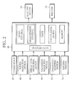
FIG. 2 is a block diagram schematically showing the tape checking apparatus ofFIG. 1 ; -
FIG. 3 is a graph showing the procedure of measurement performed by the tape checking apparatus shown inFIGS. 1 and2 ; and -
FIG. 4 is an elevation view of a tape checking apparatus according to a second embodiment of the invention. - A
tape checking apparatus 1 ofFIG. 1 has afront slide base 4 that is used for simultaneous measurement of length, thickness, width and deflection of an endless tape such as a garniture tape and extends in a vertical direction. Aroller train 3 is mounted on thefront slide base 4 and extends in a vertical direction. More specifically, theroller train 3 includesrollers front slide base 4. - The
front slide base 4 is supported by upper andlower guide rails 6. Theguide rails 6 extend in a horizontal direction. Thefront slide base 4, or theroller train 3, is therefore allowed to reciprocate along theguide rails 6 in the horizontal direction. - As viewed in
FIG. 1 , arear slide base 12 is placed on the right side of thefront slide base 4. Therear slide base 12 extends parallel to thefront slide base 4, that is, in the vertical direction, and is movably supported by theguide rails 6 as with thefront slide base 4. A pair of fixedrails 8 are placed between the upper andlower guide rails 6. Thefixed rails 8 extend close to and parallel with theirrespective guide rails 6. -
Holes 10 are formed in each of thefixed rails 8 at predetermined intervals in a longitudinal direction of thefixed rails 8. Therear slide base 12 is provided withholes 18 in its upper and lower portions. If the upper andlower holes 18 of therear slide base 12 are made to coincide withpredetermined holes 10 of their respectivefixed rails 8, and stoppers, not shown, are inserted into theholes rear slide base 12 can be fixed at a desired position relative to thefixed rails 8. - A disc-
like switch handle 14 is rotatably installed in the center of therear slide base 12 as viewed in the vertical direction through ahandle shaft 20. Theswitch handle 14 has a stopper, not shown. The stopper holds the switch handle 14 at a predetermined rotation angle. Asupport platform 26 is situated under therear slide base 12. Thesupport platform 26 is movable in a vertical direction relative to therear slide base 12 along with the rotation of theswitch handle 14. - As is apparent from
FIG. 1 , awire 22 is wound around thehandle shaft 20 of theswitch handle 14. Thewire 22 connects thefront slide base 4 and aweight 24 to each other. In the state shown in the drawing, theweight 24 pulls thefront slide base 4 towards therear slide base 12 through thewire 22. From this state, if the switch handle 14 is rotated, thesupport platform 26 is raised up to theweight 24 to support theweight 24. At this point of time, the pulling of thefront slide base 4 by theweight 24 is released. - The
front slide base 4 and therear slide base 12 are independent of each other. For this reason, thefront slide base 4 that is released from the pulling by theweight 24 can freely move alongguide rails 6, which facilitate the exchange of a garniture tape T mentioned below. - As viewed in
FIG. 1 , a drivingroller 42 is located on the left side of thefront slide base 4. The drivingroller 42 is installed so that the highest point of a circumferential face thereof is on the same level in height as the highest point of a circumferential face of theroller 31 located at the top of theroller train 3. Anelectric motor 70 is connected to the drivingroller 42. Theelectric motor 70 rotates the drivingroller 42 clockwise as viewed inFIG. 1 . - A
crown roller 40 is also installed on the left side of thefront slide base 4. Thecrown roller 40 is located between the drivingroller 42 and thefront slide base 4 to be situated nearer the drivingroller 42 in relation to thefront slide base 4. Thecrown roller 40 is installed so that the lowest point of a circumferential face thereof is on the same level in height as the lowest point of a circumferential face of theroller 36 located at the bottom of theroller train 3. - Above the
crown roller 40, aguide roller 43 is placed on the right side of the drivingroller 42. Theguide roller 43 has a smaller diameter than the drivingroller 42, and is installed so that the axis thereof is on the same level in height as the axis of the drivingroller 42. - As shown in
FIG. 1 , the drivingroller 42, the rollers of theroller train 3, thecrown roller 40 and theguide roller 43 define a running path L of an endless garniture tape T. The garniture tape T extends along the running path L. To be specific, the garniture tape T has an upper horizontal section horizontally extending between the drivingroller 42 and theroller 31, a lower horizontal section horizontally extending between theroller 36 and thecrown roller 40, and a vertical section vertically extending between thecrown roller 40 and theguide roller 43. Theguide roller 43 serves to enlarge a winding angle of the garniture tape T relative to the drivingroller 42. - In the state where the garniture tape T extends along the running path L, if the
front slide base 4 is pulled by theweight 24 towards therear slide base 12, the garniture tape T is applied with tensile force corresponding to theweight 24. If the drivingroller 42 is rotated in this state, the garniture tape T runs in one direction along the running path L while being tensioned. - Various measuring devices for measuring the dimensions of the garniture tape T and a deflection of the running garniture tape T will be described below.
- First of all, a
linear scale 28 is placed under thelower guide rail 6, and extends parallel to the guide rails 6. Thelinear scale 28 measures distance between the drivingroller 42 and thefront slide base 4. Once this distance is measured, the length of the running path L of the garniture tape T, namely, the length of the garniture tape T, can be measured. - A width-measuring
device 46 and a deflection-measuringdevice 48 are placed one above the other between thecrown roller 40 and theguide roller 43. The width-measuringdevice 46 is capable of measuring the width of the garniture tape T, whereas the deflection-measuringdevice 48 is capable of measuring the deflection of the garniture tape T while the garniture tape T is running. More specifically, the width-measuringdevice 46 and the deflection-measuringdevice 48 each have a light source and a CCD camera which are disposed across the vertical section of the garniture tape T. The width and deflection of the garniture tape T are measured on the basis of image data of the garniture tape T, which is photographed by the CCD camera. - The
crown roller 40 located upstream of the width-measuringdevice 46 and the deflection-measuringdevice 48 has a function to automatically correct a deviation of the garniture tape T from the running path L (centering function). This enables the width-measuringdevice 46 and the deflection-measuringdevice 48 to measure the width and deflection of the garniture tape T with more accuracy. - A
pinch roller 45 is set immediately above the drivingroller 42. Thepinch roller 45 is supported to be displaceable in the vertical direction, and pinches the garniture tape T between itself and the drivingroller 42. A thickness-measuringdevice 44 is placed near thepinch roller 45. The thickness-measuringdevice 44 is also formed of a light source and a CCD camera which are disposed across thepinch roller 45. The thickness-measuringdevice 44 uses the CCD camera to photograph the garniture tape T passing between the drivingroller 42 and thepinch roller 45, and measures the thickness of the garniture tape T on the basis of the image data obtained by the photographing. - Since the garniture tape T is pinched between the driving
roller 42 and thepinch roller 45, warpage or distortion of the garniture tape T does not affect the measurement, and therefore, the thickness of the garniture tape T is accurately measured. - As shown in
FIG. 2 , ameasurement controller 60 is connected through serial communication lines not only to theelectric motor 70, thelinear scale 28, the width-measuringdevice 46, the deflection-measuringdevice 48 and the thickness-measuringdevice 44, but also to aswitch 72 for starting an operation, a settingswitch 74 for setting measurement intervals, aprinter 76 for outputting a measurement result, and a display, not shown. After the operation-startingswitch 72 is turned ON, themeasurement controller 60 of the present embodiment exerts a function to control the running speed of the garniture tape T in addition to a function to control the measurement of the garniture tape T. In other words, themeasurement controller 60 concurrently implements measurement control and speed control on the garniture tape T. In other words, while controlling the running speed of the garniture tape T, themeasurement controller 60 reads the detected signals (data) transmitted from thelinear scale 28 and the measuringdevices measurement controller 60 includes a timer, and further has a function to calibrate the deflection-measuringdevice 48. - To be more specific, after the operation-starting
switch 72 is turned ON as shown inFIG. 3 , themeasurement controller 60 implements the preparatory run of the garniture tape T for a predetermined duration prior to the start of the measurement. The duration of the preparatory run is measured by the timer. The speed of the preparatory run is set faster than the measurement-time speed of the garniture tape T during the measurement mentioned later. The preparatory run stabilizes the tension and running course of the garniture tape T provided with tensile force, and is thus effective to perform the subsequent measurement of the garniture tape T with high accuracy. - When the preparatory run is ended, the
measurement controller 60 reduces the running speed of the garniture tape T to the measurement-time speed and maintains the running speed at the measurement-time speed. At this point of time, themeasurement controller 60 indicates on a display, not shown, thereof that the measurement has been started. - Thereafter, when an elapse of a predetermined time period is measured by the timer, the
measurement controller 60 automatically carries out an auto-zeroing function that zeros a deflection amount measured by the deflection-measuringdevice 48 and thus calibrates the deflection-measuringdevice 48. - When the measurement is ready, the timer measures the elapse of a given length of time, and the
measurement controller 60 indicates on the display that the measurement is in process. Meanwhile, the detected signals transmitted from thelinear scale 28, the width-measuringdevice 46, the deflection-measuringdevice 48 and the thickness-measuringdevice 44, namely, measured data, is read in at the measurement intervals preset by the settingswitch 74, for example, every 100 ms. - The
measurement controller 60 further includes a calculation device. The calculation device calculates maximum and minimum values of the length, width, deflection, and thickness of the garniture tape T on the basis of measured data that has been read in, and then stores a calculation result in a memory. - At the time point when the entire length of the garniture tape T, namely, the measured data of one round of the garniture tape T, is collected by the
measurement controller 60, that is, at the elapse of measurement time mentioned below, themeasurement controller 60 stops the run of the garniture tape T, and indicates on the display a measurement result and that the measurement is finished. At the same time, themeasurement controller 60 causes theprinter 76 to print out the measurement result as occasion demands. - Prior to the foregoing measurement, the
measurement controller 60 beforehand automatically calculates the measurement time on the basis of predetermined length and measurement-time speed of the garniture tape T. Themeasurement controller 60 may arbitrarily set the measurement intervals, or reading intervals, of each data, and also may easily vary a measurement accuracy if necessary. - For example, in order to measure every 10 mm of the garniture tape T, the measured data is read in every 100 ms, and the measurement-time speed of the garniture tape T is 6 m/min. If the measurement-time speed of the garniture tape T is doubled, the measured data is read in with respect to every 20 mm.
- Since the measurement of the garniture tape T is automatically carried out in the running process of the garniture tape T as described above, it is possible to resolve variations of the measurement result, which are unavoidable when a measurer uses measuring tools to perform measurement. It is also possible to measure the length, width, deflection and thickness of the garniture tape T simultaneously in a short period of time.
- A tape checking apparatus of a second embodiment will be described below with reference to
FIG. 4 . - The checking apparatus of the second embodiment further has a fixed
roller train 5. Theroller train 5 is disposed between theroller train 3 and thecrown roller 40, extending parallel with theroller train 3. - To be more specific, the
roller train 5 includes fourrollers rollers rollers rollers rollers rollers - With the
roller train 5, the garniture tape T can be hung alternately between theroller train 3 and theroller train 5 as shown inFIG. 4 . This enables to elongate the running path L, and even the garniture tape T increased in length can be measured in the same manner as in the first embodiment. - The invention is not limited to the embodiments, and may be modified without deviating from the technical idea thereof. For example, the invention is applicable not only to the measurement of the garniture tape but also to that of various kinds of endless tapes.
-
- 1
- tape checking apparatus
- 3
- roller train
- 4
- front slide base
- 5
- roller train
- 6
- guide rail
- 8
- fixed rail
- 10
- hole
- 12
- rear slide base
- 14
- switch handle
- 18
- hole
- 28
- linear scale
- 40
- crown roller
- 42
- driving roller
- 43
- guide roller
- 44
- thickness-measuring device
- 45
- pinch roller
- 46
- width-measuring device
- 48
- deflection-measuring device
- 60
- measurement controller
- 70
- motor
- L
- running path
- T
- garniture tape
Claims (10)
- A tape checking apparatus comprising:a running path for guiding a run of an endless tape, said running path including a rotatable driving roller;a slide base arranged for moving toward and away from the driving roller;a roller train disposed in said slide base, said roller train forming a part of said running path and applying tensile force to the endless tape; anda length-measuring device and a thickness-measuring device interposed in said running path for measuring length and thickness of the endless tape, respectively, wherein:said thickness-measuring device includes a pinch roller for pressing the endless tape against a circumferential surface of the driving roller, and measures the thickness of the endless tape passing between the pinch roller and the driving roller.
- The tape checking apparatus according to claim 1, wherein said slide base is movable in a horizontal direction, and said roller train extends in a vertical direction.
- The tape checking apparatus according to claim 2, further comprising:a crown roller interposed in the running path to be located on the upstream side of the driving roller, for guiding the run of the endless tape.
- The tape checking apparatus according to claim 3, further comprising:a width-measuring device for measuring width of the endless tape, wherein:said width-measuring device is placed in said running path where the endless tape runs from said crown roller towards the driving roller.
- The tape checking apparatus according to claim 3, further comprising:a deflection-measuring device for measuring deflection of the endless tape, wherein:said deflection-measuring device is placed in said running path where the endless tape runs from said crown roller towards the driving roller.
- The tape checking apparatus according to claim 1, wherein said length-measuring device includes a linear scale for measuring a distance between the driving roller and said roller train.
- The tape checking apparatus according to claim 1, further comprising:a guide roller disposed near the driving roller, for guiding the run of the endless tape, wherein:said guide roller determines a winding angle of the endless tape on the driving roller to 180 degrees or more, and the driving roller has a larger diameter than said guide roller.
- The tape checking apparatus according to claim 5, further comprising:a measurement controller for controlling a running speed of the endless tape and a measurement timing of each said measuring device, wherein:said measurement controller makes the endless tape run at a preparatory speed being faster than a speed during measurement time in which the length, width, deflection and thickness of the endless tape are measured; and after an elapse of a certain period of time, said measurement controller commences the measurement of the length, width, deflection and thickness in a state where the running speed of the endless tape is reduced to and maintained at the measurement-time speed.
- The tape checking apparatus according to claim 8, wherein said measurement controller has a function to calibrate a measurement result of said deflection-measuring device immediately before measurement to a deflection amount of zero.
- The tape checking apparatus according to claim 8, wherein said measurement controller includes setting means for arbitrarily setting an interval of measurement of width, deflection and thickness of the endless tape.
Applications Claiming Priority (2)
| Application Number | Priority Date | Filing Date | Title |
|---|---|---|---|
| JP2009061168 | 2009-03-13 | ||
| PCT/JP2010/053548 WO2010103991A1 (en) | 2009-03-13 | 2010-03-04 | Tape inspecting apparatus |
Publications (3)
| Publication Number | Publication Date |
|---|---|
| EP2407750A1 true EP2407750A1 (en) | 2012-01-18 |
| EP2407750A4 EP2407750A4 (en) | 2015-04-01 |
| EP2407750B1 EP2407750B1 (en) | 2018-01-24 |
Family
ID=42728281
Family Applications (1)
| Application Number | Title | Priority Date | Filing Date |
|---|---|---|---|
| EP10750745.1A Not-in-force EP2407750B1 (en) | 2009-03-13 | 2010-03-04 | Tape checking apparatus |
Country Status (5)
| Country | Link |
|---|---|
| US (1) | US8191279B2 (en) |
| EP (1) | EP2407750B1 (en) |
| JP (1) | JP5207419B2 (en) |
| BR (1) | BRPI1009395A2 (en) |
| WO (1) | WO2010103991A1 (en) |
Families Citing this family (1)
| Publication number | Priority date | Publication date | Assignee | Title |
|---|---|---|---|---|
| CN102175113B (en) * | 2011-01-19 | 2012-11-14 | 云南烟草科学研究院 | Tobacco combustion char length measuring instrument |
Citations (6)
| Publication number | Priority date | Publication date | Assignee | Title |
|---|---|---|---|---|
| US3019574A (en) * | 1959-04-09 | 1962-02-06 | American Mach & Foundry | Automatic cigarette catcher |
| EP0393589A1 (en) * | 1989-04-17 | 1990-10-24 | Omron Corporation | Continuous paper let-out apparatus |
| EP0726031A1 (en) * | 1995-02-09 | 1996-08-14 | Japan Tobacco Inc. | Cigarette rod manufacturing apparatus |
| US20030016959A1 (en) * | 2001-07-17 | 2003-01-23 | Oki Data Corporation | Image-forming apparatus |
| EP1424016A1 (en) * | 2002-11-29 | 2004-06-02 | Hauni Maschinenbau AG | Circulating conveyor belt for transporting a rod of the tobacco industry |
| US20080133051A1 (en) * | 2006-12-05 | 2008-06-05 | The Goodyear Tire & Rubber Company | Remote conveyor belt monitoring system and method |
Family Cites Families (9)
| Publication number | Priority date | Publication date | Assignee | Title |
|---|---|---|---|---|
| US2091177A (en) * | 1936-04-25 | 1937-08-24 | Plymouth Cordage Co | Combined displaying and dispensing device for linear articles |
| US3758954A (en) * | 1971-04-23 | 1973-09-18 | Steel Corp | Apparatus for measuring lengths of linear material |
| JPS6042046U (en) * | 1983-08-25 | 1985-03-25 | 松下電工株式会社 | emergency power supply |
| JPS6242046U (en) * | 1985-08-30 | 1987-03-13 | ||
| JPH0738804Y2 (en) * | 1989-11-08 | 1995-09-06 | バンドー化学株式会社 | Length measuring device for power transmission belts |
| SE466276B (en) * | 1990-05-17 | 1992-01-20 | Ericsson Telefon Ab L M | LENGTH SEATING EQUIPMENT FOR SEATING LONG-TREATED MATERIAL, LIKE CABLES |
| DE9102864U1 (en) * | 1991-03-09 | 1991-05-29 | Hacoba Textilmaschinen Gmbh & Co Kg, 5600 Wuppertal, De | |
| US5351531A (en) * | 1993-05-10 | 1994-10-04 | Kerr Measurement Systems, Inc. | Depth measurement of slickline |
| JPH06323801A (en) | 1993-05-17 | 1994-11-25 | Bando Chem Ind Ltd | Belt measuring device |
-
2010
- 2010-03-04 EP EP10750745.1A patent/EP2407750B1/en not_active Not-in-force
- 2010-03-04 BR BRPI1009395A patent/BRPI1009395A2/en not_active Application Discontinuation
- 2010-03-04 JP JP2011503786A patent/JP5207419B2/en not_active Expired - Fee Related
- 2010-03-04 WO PCT/JP2010/053548 patent/WO2010103991A1/en active Application Filing
-
2011
- 2011-07-05 US US13/176,545 patent/US8191279B2/en not_active Expired - Fee Related
Patent Citations (6)
| Publication number | Priority date | Publication date | Assignee | Title |
|---|---|---|---|---|
| US3019574A (en) * | 1959-04-09 | 1962-02-06 | American Mach & Foundry | Automatic cigarette catcher |
| EP0393589A1 (en) * | 1989-04-17 | 1990-10-24 | Omron Corporation | Continuous paper let-out apparatus |
| EP0726031A1 (en) * | 1995-02-09 | 1996-08-14 | Japan Tobacco Inc. | Cigarette rod manufacturing apparatus |
| US20030016959A1 (en) * | 2001-07-17 | 2003-01-23 | Oki Data Corporation | Image-forming apparatus |
| EP1424016A1 (en) * | 2002-11-29 | 2004-06-02 | Hauni Maschinenbau AG | Circulating conveyor belt for transporting a rod of the tobacco industry |
| US20080133051A1 (en) * | 2006-12-05 | 2008-06-05 | The Goodyear Tire & Rubber Company | Remote conveyor belt monitoring system and method |
Non-Patent Citations (1)
| Title |
|---|
| See also references of WO2010103991A1 * |
Also Published As
| Publication number | Publication date |
|---|---|
| EP2407750B1 (en) | 2018-01-24 |
| US8191279B2 (en) | 2012-06-05 |
| WO2010103991A1 (en) | 2010-09-16 |
| US20110258871A1 (en) | 2011-10-27 |
| JP5207419B2 (en) | 2013-06-12 |
| EP2407750A4 (en) | 2015-04-01 |
| BRPI1009395A2 (en) | 2016-03-08 |
| JPWO2010103991A1 (en) | 2012-09-13 |
Similar Documents
| Publication | Publication Date | Title |
|---|---|---|
| EP0649730A1 (en) | Method for adjusting a side of a strip of flexible material to a reference side and apparatus for feeding a belt strip on a rotating building drum | |
| CA2664410C (en) | Method and device for winding metal strips onto a coiling mandrel | |
| CN110422690B (en) | 3D printing flexible wire winding device and working method thereof | |
| CN112020753B (en) | Twisting device and method for determining or testing the lay length of a cable bundle, computer-implemented method, and computer program product and upgrade kit | |
| US8191279B2 (en) | Tape checking apparatus | |
| RU2542550C1 (en) | Device of correction of step of printing for plastic film | |
| CN208569644U (en) | A kind of quick barcode scanning test device based on slide unit | |
| EP2105397A2 (en) | Yarn unwinding assisting device for automatic winder | |
| JP2755532B2 (en) | Continuous winding device for strip-shaped wire and control method thereof | |
| JP2002166482A (en) | Apparatus for manufacturing long-sized endless toothed belt and method for counting number of teeth | |
| JP5684021B2 (en) | Electric wire processing equipment | |
| TW200916398A (en) | Wire winding method and wire winding machine | |
| CN210064656U (en) | Comprehensive detection device for ultrathin nanocrystalline strip | |
| US20050044948A1 (en) | System and method for automatically measuring and tracking a feature of material used during a manufacturing process | |
| JP2000039314A (en) | Cigarette inspecting device | |
| JP4317333B2 (en) | Adhesive force measuring machine | |
| EP2192066A3 (en) | Method and arrangement for controlling winder device operation | |
| CN203919755U (en) | For the splicing apparatus of superimposed splicing cord tape | |
| JP4426233B2 (en) | Cutting method and cutting apparatus | |
| KR102354545B1 (en) | A Sampling and Testing Equipment for Coil | |
| KR101431430B1 (en) | taping machine | |
| CN218854701U (en) | Composite control system with unified width reference and automatic alignment | |
| KR101320147B1 (en) | Side guide automatic control apparatus for preventing strip serpentine movement | |
| JP3857778B2 (en) | Transmission belt cutting device | |
| JP2997891B2 (en) | Web winding apparatus made of synthetic resin film and synthetic resin film manufacturing apparatus using the same |
Legal Events
| Date | Code | Title | Description |
|---|---|---|---|
| PUAI | Public reference made under article 153(3) epc to a published international application that has entered the european phase |
Free format text: ORIGINAL CODE: 0009012 |
|
| 17P | Request for examination filed |
Effective date: 20110708 |
|
| AK | Designated contracting states |
Kind code of ref document: A1 Designated state(s): AT BE BG CH CY CZ DE DK EE ES FI FR GB GR HR HU IE IS IT LI LT LU LV MC MK MT NL NO PL PT RO SE SI SK SM TR |
|
| DAX | Request for extension of the european patent (deleted) | ||
| A4 | Supplementary search report drawn up and despatched |
Effective date: 20150302 |
|
| RIC1 | Information provided on ipc code assigned before grant |
Ipc: G01B 21/08 20060101ALI20150224BHEP Ipc: A24C 5/14 20060101AFI20150224BHEP Ipc: B65G 15/00 20060101ALI20150224BHEP |
|
| REG | Reference to a national code |
Ref country code: DE Ref legal event code: R079 Ref document number: 602010048235 Country of ref document: DE Free format text: PREVIOUS MAIN CLASS: G01B0005020000 Ipc: G01B0021080000 |
|
| GRAP | Despatch of communication of intention to grant a patent |
Free format text: ORIGINAL CODE: EPIDOSNIGR1 |
|
| STAA | Information on the status of an ep patent application or granted ep patent |
Free format text: STATUS: GRANT OF PATENT IS INTENDED |
|
| RIC1 | Information provided on ipc code assigned before grant |
Ipc: G01B 21/08 20060101AFI20170831BHEP Ipc: B65G 15/00 20060101ALI20170831BHEP Ipc: A24C 5/14 20060101ALI20170831BHEP |
|
| INTG | Intention to grant announced |
Effective date: 20170914 |
|
| RIN1 | Information on inventor provided before grant (corrected) |
Inventor name: SUZUKI, NORIO Inventor name: HYODO, SHINICHI Inventor name: ARAKAWA, TOYOMI |
|
| GRAS | Grant fee paid |
Free format text: ORIGINAL CODE: EPIDOSNIGR3 |
|
| GRAA | (expected) grant |
Free format text: ORIGINAL CODE: 0009210 |
|
| STAA | Information on the status of an ep patent application or granted ep patent |
Free format text: STATUS: THE PATENT HAS BEEN GRANTED |
|
| AK | Designated contracting states |
Kind code of ref document: B1 Designated state(s): AT BE BG CH CY CZ DE DK EE ES FI FR GB GR HR HU IE IS IT LI LT LU LV MC MK MT NL NO PL PT RO SE SI SK SM TR |
|
| REG | Reference to a national code |
Ref country code: GB Ref legal event code: FG4D |
|
| REG | Reference to a national code |
Ref country code: CH Ref legal event code: EP |
|
| REG | Reference to a national code |
Ref country code: AT Ref legal event code: REF Ref document number: 966016 Country of ref document: AT Kind code of ref document: T Effective date: 20180215 Ref country code: CH Ref legal event code: NV Representative=s name: NOVAGRAAF INTERNATIONAL SA, CH |
|
| REG | Reference to a national code |
Ref country code: IE Ref legal event code: FG4D |
|
| REG | Reference to a national code |
Ref country code: DE Ref legal event code: R096 Ref document number: 602010048235 Country of ref document: DE |
|
| PGFP | Annual fee paid to national office [announced via postgrant information from national office to epo] |
Ref country code: CH Payment date: 20180321 Year of fee payment: 9 Ref country code: GB Payment date: 20180321 Year of fee payment: 9 |
|
| REG | Reference to a national code |
Ref country code: NL Ref legal event code: MP Effective date: 20180124 |
|
| REG | Reference to a national code |
Ref country code: LT Ref legal event code: MG4D |
|
| REG | Reference to a national code |
Ref country code: AT Ref legal event code: MK05 Ref document number: 966016 Country of ref document: AT Kind code of ref document: T Effective date: 20180124 |
|
| PG25 | Lapsed in a contracting state [announced via postgrant information from national office to epo] |
Ref country code: NL Free format text: LAPSE BECAUSE OF FAILURE TO SUBMIT A TRANSLATION OF THE DESCRIPTION OR TO PAY THE FEE WITHIN THE PRESCRIBED TIME-LIMIT Effective date: 20180124 |
|
| PG25 | Lapsed in a contracting state [announced via postgrant information from national office to epo] |
Ref country code: NO Free format text: LAPSE BECAUSE OF FAILURE TO SUBMIT A TRANSLATION OF THE DESCRIPTION OR TO PAY THE FEE WITHIN THE PRESCRIBED TIME-LIMIT Effective date: 20180424 Ref country code: FI Free format text: LAPSE BECAUSE OF FAILURE TO SUBMIT A TRANSLATION OF THE DESCRIPTION OR TO PAY THE FEE WITHIN THE PRESCRIBED TIME-LIMIT Effective date: 20180124 Ref country code: LT Free format text: LAPSE BECAUSE OF FAILURE TO SUBMIT A TRANSLATION OF THE DESCRIPTION OR TO PAY THE FEE WITHIN THE PRESCRIBED TIME-LIMIT Effective date: 20180124 Ref country code: HR Free format text: LAPSE BECAUSE OF FAILURE TO SUBMIT A TRANSLATION OF THE DESCRIPTION OR TO PAY THE FEE WITHIN THE PRESCRIBED TIME-LIMIT Effective date: 20180124 Ref country code: ES Free format text: LAPSE BECAUSE OF FAILURE TO SUBMIT A TRANSLATION OF THE DESCRIPTION OR TO PAY THE FEE WITHIN THE PRESCRIBED TIME-LIMIT Effective date: 20180124 Ref country code: CY Free format text: LAPSE BECAUSE OF FAILURE TO SUBMIT A TRANSLATION OF THE DESCRIPTION OR TO PAY THE FEE WITHIN THE PRESCRIBED TIME-LIMIT Effective date: 20180124 |
|
| PGFP | Annual fee paid to national office [announced via postgrant information from national office to epo] |
Ref country code: DE Payment date: 20180329 Year of fee payment: 9 |
|
| PG25 | Lapsed in a contracting state [announced via postgrant information from national office to epo] |
Ref country code: GR Free format text: LAPSE BECAUSE OF FAILURE TO SUBMIT A TRANSLATION OF THE DESCRIPTION OR TO PAY THE FEE WITHIN THE PRESCRIBED TIME-LIMIT Effective date: 20180425 Ref country code: BG Free format text: LAPSE BECAUSE OF FAILURE TO SUBMIT A TRANSLATION OF THE DESCRIPTION OR TO PAY THE FEE WITHIN THE PRESCRIBED TIME-LIMIT Effective date: 20180424 Ref country code: IS Free format text: LAPSE BECAUSE OF FAILURE TO SUBMIT A TRANSLATION OF THE DESCRIPTION OR TO PAY THE FEE WITHIN THE PRESCRIBED TIME-LIMIT Effective date: 20180524 Ref country code: PL Free format text: LAPSE BECAUSE OF FAILURE TO SUBMIT A TRANSLATION OF THE DESCRIPTION OR TO PAY THE FEE WITHIN THE PRESCRIBED TIME-LIMIT Effective date: 20180124 Ref country code: LV Free format text: LAPSE BECAUSE OF FAILURE TO SUBMIT A TRANSLATION OF THE DESCRIPTION OR TO PAY THE FEE WITHIN THE PRESCRIBED TIME-LIMIT Effective date: 20180124 Ref country code: SE Free format text: LAPSE BECAUSE OF FAILURE TO SUBMIT A TRANSLATION OF THE DESCRIPTION OR TO PAY THE FEE WITHIN THE PRESCRIBED TIME-LIMIT Effective date: 20180124 Ref country code: AT Free format text: LAPSE BECAUSE OF FAILURE TO SUBMIT A TRANSLATION OF THE DESCRIPTION OR TO PAY THE FEE WITHIN THE PRESCRIBED TIME-LIMIT Effective date: 20180124 |
|
| PGFP | Annual fee paid to national office [announced via postgrant information from national office to epo] |
Ref country code: IT Payment date: 20180427 Year of fee payment: 9 |
|
| REG | Reference to a national code |
Ref country code: DE Ref legal event code: R097 Ref document number: 602010048235 Country of ref document: DE |
|
| PG25 | Lapsed in a contracting state [announced via postgrant information from national office to epo] |
Ref country code: EE Free format text: LAPSE BECAUSE OF FAILURE TO SUBMIT A TRANSLATION OF THE DESCRIPTION OR TO PAY THE FEE WITHIN THE PRESCRIBED TIME-LIMIT Effective date: 20180124 Ref country code: RO Free format text: LAPSE BECAUSE OF FAILURE TO SUBMIT A TRANSLATION OF THE DESCRIPTION OR TO PAY THE FEE WITHIN THE PRESCRIBED TIME-LIMIT Effective date: 20180124 |
|
| PG25 | Lapsed in a contracting state [announced via postgrant information from national office to epo] |
Ref country code: MC Free format text: LAPSE BECAUSE OF FAILURE TO SUBMIT A TRANSLATION OF THE DESCRIPTION OR TO PAY THE FEE WITHIN THE PRESCRIBED TIME-LIMIT Effective date: 20180124 Ref country code: CZ Free format text: LAPSE BECAUSE OF FAILURE TO SUBMIT A TRANSLATION OF THE DESCRIPTION OR TO PAY THE FEE WITHIN THE PRESCRIBED TIME-LIMIT Effective date: 20180124 Ref country code: SM Free format text: LAPSE BECAUSE OF FAILURE TO SUBMIT A TRANSLATION OF THE DESCRIPTION OR TO PAY THE FEE WITHIN THE PRESCRIBED TIME-LIMIT Effective date: 20180124 Ref country code: SK Free format text: LAPSE BECAUSE OF FAILURE TO SUBMIT A TRANSLATION OF THE DESCRIPTION OR TO PAY THE FEE WITHIN THE PRESCRIBED TIME-LIMIT Effective date: 20180124 Ref country code: DK Free format text: LAPSE BECAUSE OF FAILURE TO SUBMIT A TRANSLATION OF THE DESCRIPTION OR TO PAY THE FEE WITHIN THE PRESCRIBED TIME-LIMIT Effective date: 20180124 |
|
| PLBE | No opposition filed within time limit |
Free format text: ORIGINAL CODE: 0009261 |
|
| STAA | Information on the status of an ep patent application or granted ep patent |
Free format text: STATUS: NO OPPOSITION FILED WITHIN TIME LIMIT |
|
| REG | Reference to a national code |
Ref country code: BE Ref legal event code: MM Effective date: 20180331 |
|
| REG | Reference to a national code |
Ref country code: IE Ref legal event code: MM4A |
|
| PG25 | Lapsed in a contracting state [announced via postgrant information from national office to epo] |
Ref country code: LU Free format text: LAPSE BECAUSE OF NON-PAYMENT OF DUE FEES Effective date: 20180304 |
|
| 26N | No opposition filed |
Effective date: 20181025 |
|
| PG25 | Lapsed in a contracting state [announced via postgrant information from national office to epo] |
Ref country code: IE Free format text: LAPSE BECAUSE OF NON-PAYMENT OF DUE FEES Effective date: 20180304 |
|
| PG25 | Lapsed in a contracting state [announced via postgrant information from national office to epo] |
Ref country code: BE Free format text: LAPSE BECAUSE OF NON-PAYMENT OF DUE FEES Effective date: 20180331 Ref country code: SI Free format text: LAPSE BECAUSE OF FAILURE TO SUBMIT A TRANSLATION OF THE DESCRIPTION OR TO PAY THE FEE WITHIN THE PRESCRIBED TIME-LIMIT Effective date: 20180124 |
|
| PG25 | Lapsed in a contracting state [announced via postgrant information from national office to epo] |
Ref country code: FR Free format text: LAPSE BECAUSE OF NON-PAYMENT OF DUE FEES Effective date: 20180324 |
|
| REG | Reference to a national code |
Ref country code: DE Ref legal event code: R119 Ref document number: 602010048235 Country of ref document: DE |
|
| REG | Reference to a national code |
Ref country code: CH Ref legal event code: PL |
|
| GBPC | Gb: european patent ceased through non-payment of renewal fee |
Effective date: 20190304 |
|
| PG25 | Lapsed in a contracting state [announced via postgrant information from national office to epo] |
Ref country code: CH Free format text: LAPSE BECAUSE OF NON-PAYMENT OF DUE FEES Effective date: 20190331 Ref country code: GB Free format text: LAPSE BECAUSE OF NON-PAYMENT OF DUE FEES Effective date: 20190304 Ref country code: LI Free format text: LAPSE BECAUSE OF NON-PAYMENT OF DUE FEES Effective date: 20190331 Ref country code: DE Free format text: LAPSE BECAUSE OF NON-PAYMENT OF DUE FEES Effective date: 20191001 Ref country code: MT Free format text: LAPSE BECAUSE OF NON-PAYMENT OF DUE FEES Effective date: 20180304 |
|
| PG25 | Lapsed in a contracting state [announced via postgrant information from national office to epo] |
Ref country code: IT Free format text: LAPSE BECAUSE OF NON-PAYMENT OF DUE FEES Effective date: 20190304 |
|
| PG25 | Lapsed in a contracting state [announced via postgrant information from national office to epo] |
Ref country code: TR Free format text: LAPSE BECAUSE OF FAILURE TO SUBMIT A TRANSLATION OF THE DESCRIPTION OR TO PAY THE FEE WITHIN THE PRESCRIBED TIME-LIMIT Effective date: 20180124 |
|
| PG25 | Lapsed in a contracting state [announced via postgrant information from national office to epo] |
Ref country code: PT Free format text: LAPSE BECAUSE OF FAILURE TO SUBMIT A TRANSLATION OF THE DESCRIPTION OR TO PAY THE FEE WITHIN THE PRESCRIBED TIME-LIMIT Effective date: 20180124 Ref country code: HU Free format text: LAPSE BECAUSE OF FAILURE TO SUBMIT A TRANSLATION OF THE DESCRIPTION OR TO PAY THE FEE WITHIN THE PRESCRIBED TIME-LIMIT; INVALID AB INITIO Effective date: 20100304 |
|
| PG25 | Lapsed in a contracting state [announced via postgrant information from national office to epo] |
Ref country code: MK Free format text: LAPSE BECAUSE OF NON-PAYMENT OF DUE FEES Effective date: 20180124 |