EP2407644B1 - Turbofantriebwerk mit Getriebe - Google Patents
Turbofantriebwerk mit Getriebe Download PDFInfo
- Publication number
- EP2407644B1 EP2407644B1 EP11173891.0A EP11173891A EP2407644B1 EP 2407644 B1 EP2407644 B1 EP 2407644B1 EP 11173891 A EP11173891 A EP 11173891A EP 2407644 B1 EP2407644 B1 EP 2407644B1
- Authority
- EP
- European Patent Office
- Prior art keywords
- drive
- brake
- gear
- engine
- planetary
- Prior art date
- Legal status (The legal status is an assumption and is not a legal conclusion. Google has not performed a legal analysis and makes no representation as to the accuracy of the status listed.)
- Active
Links
Images

Classifications
-
- F—MECHANICAL ENGINEERING; LIGHTING; HEATING; WEAPONS; BLASTING
- F01—MACHINES OR ENGINES IN GENERAL; ENGINE PLANTS IN GENERAL; STEAM ENGINES
- F01D—NON-POSITIVE DISPLACEMENT MACHINES OR ENGINES, e.g. STEAM TURBINES
- F01D21/00—Shutting-down of machines or engines, e.g. in emergency; Regulating, controlling, or safety means not otherwise provided for
- F01D21/006—Arrangements of brakes
-
- F—MECHANICAL ENGINEERING; LIGHTING; HEATING; WEAPONS; BLASTING
- F02—COMBUSTION ENGINES; HOT-GAS OR COMBUSTION-PRODUCT ENGINE PLANTS
- F02C—GAS-TURBINE PLANTS; AIR INTAKES FOR JET-PROPULSION PLANTS; CONTROLLING FUEL SUPPLY IN AIR-BREATHING JET-PROPULSION PLANTS
- F02C7/00—Features, components parts, details or accessories, not provided for in, or of interest apart form groups F02C1/00 - F02C6/00; Air intakes for jet-propulsion plants
- F02C7/36—Power transmission arrangements between the different shafts of the gas turbine plant, or between the gas-turbine plant and the power user
-
- F—MECHANICAL ENGINEERING; LIGHTING; HEATING; WEAPONS; BLASTING
- F02—COMBUSTION ENGINES; HOT-GAS OR COMBUSTION-PRODUCT ENGINE PLANTS
- F02K—JET-PROPULSION PLANTS
- F02K3/00—Plants including a gas turbine driving a compressor or a ducted fan
- F02K3/02—Plants including a gas turbine driving a compressor or a ducted fan in which part of the working fluid by-passes the turbine and combustion chamber
- F02K3/04—Plants including a gas turbine driving a compressor or a ducted fan in which part of the working fluid by-passes the turbine and combustion chamber the plant including ducted fans, i.e. fans with high volume, low pressure outputs, for augmenting the jet thrust, e.g. of double-flow type
- F02K3/06—Plants including a gas turbine driving a compressor or a ducted fan in which part of the working fluid by-passes the turbine and combustion chamber the plant including ducted fans, i.e. fans with high volume, low pressure outputs, for augmenting the jet thrust, e.g. of double-flow type with front fan
-
- F—MECHANICAL ENGINEERING; LIGHTING; HEATING; WEAPONS; BLASTING
- F05—INDEXING SCHEMES RELATING TO ENGINES OR PUMPS IN VARIOUS SUBCLASSES OF CLASSES F01-F04
- F05D—INDEXING SCHEME FOR ASPECTS RELATING TO NON-POSITIVE-DISPLACEMENT MACHINES OR ENGINES, GAS-TURBINES OR JET-PROPULSION PLANTS
- F05D2260/00—Function
- F05D2260/90—Braking
-
- F—MECHANICAL ENGINEERING; LIGHTING; HEATING; WEAPONS; BLASTING
- F05—INDEXING SCHEMES RELATING TO ENGINES OR PUMPS IN VARIOUS SUBCLASSES OF CLASSES F01-F04
- F05D—INDEXING SCHEME FOR ASPECTS RELATING TO NON-POSITIVE-DISPLACEMENT MACHINES OR ENGINES, GAS-TURBINES OR JET-PROPULSION PLANTS
- F05D2270/00—Control
- F05D2270/01—Purpose of the control system
- F05D2270/09—Purpose of the control system to cope with emergencies
-
- Y—GENERAL TAGGING OF NEW TECHNOLOGICAL DEVELOPMENTS; GENERAL TAGGING OF CROSS-SECTIONAL TECHNOLOGIES SPANNING OVER SEVERAL SECTIONS OF THE IPC; TECHNICAL SUBJECTS COVERED BY FORMER USPC CROSS-REFERENCE ART COLLECTIONS [XRACs] AND DIGESTS
- Y10—TECHNICAL SUBJECTS COVERED BY FORMER USPC
- Y10T—TECHNICAL SUBJECTS COVERED BY FORMER US CLASSIFICATION
- Y10T74/00—Machine element or mechanism
- Y10T74/19—Gearing
- Y10T74/19637—Gearing with brake means for gearing
Definitions
- the present disclosure relates generally to gas turbine engines and more particularly to an apparatus to selectively disengage components of a geared turbofan gas turbine engine in an emergency condition.
- Aircraft geared turbofan engines in which a geared differential connects a low pressure turbine to a fan, are known to provide good fuel economy relative to other types of aircraft gas turbine engines.
- a differential gives engine designers flexibility to independently optimize the fan and low pressure turbine speeds and efficiency via the differential input to output speed ratios.
- US 2006/137355 A1 discloses an electrical generator in a gas turbine engine which is coupled to a clutch assembly through a speed increasing gearset.
- the gearset increases the rotational speed of the electrical generator when the clutch assembly connects the electrical generator with a low pressure spool shaft during a windmill action of a fan assembly.
- the speed increasing gear set comprises a plate having a central shaft coupled with the output end of the clutch assembly and includes an inner gear ring extending circumferentially around the periphery thereof.
- a small central gear is provided with a central shaft which is coupled with the electrical generator.
- the central gear gears into the inner gear of the plate through a pair of idle gears rotatably supported by a stationary structure.
- EP 1918564 A2 discloses that during engine operation, a fan section for a turbofan engine is driven by a fan drive system that includes a planetary gear system. When the engine is not operating, wind passing over the fan can cause the fan to windmill. If the engine is shut down whilst the aircraft is on the ground, a brake is applied to prevent rotation of the fan. Specifically, a generator connected to the fan drive gear system is shorted to provide a dynamic brake. The generator creates drag on the fan and prevents the fan from rotating. A brake can also be mounted around the rotor shaft to clamp the rotor shaft to prevent rotation.
- a fan drive for an aircraft comprising: a gearbox comprising: a planetary gear carrier; a first brake for braking the planetary gear carrier against rotation thereof; planetary gears mounted in the planetary gear carrier; a ring gear mounted to drive or be driven by the planetary gears; a sun gear mounted to drive the planetary gears; a second brake for braking the sun gear against rotation thereof; and a shaft connected to drive the sun gear; and an engine fan coupled to the ring gear and drivable thereby, wherein the first brake is arranged to brake the planetary gear carrier to cause the shaft to drive the sun gear to drive the planetary gears to drive the ring gear to drive the engine fan; and the second brake is arranged to brake the sun gear when the first brake is released so as to cause the engine fan to drive the ring gear to drive the planetary gears to drive the planetary gear carrier.
- a method, according to claim 5, for selectively disengaging components of a turbofan gas turbine engine in an emergency condition comprising: providing a gearbox comprising: a planetary gear carrier; a first brake for braking the planetary gear carrier against rotation thereof; planetary gears mounted in the planetary gear carrier; a ring gear mounted to drive or be driven by the planetary gears; a sun gear mounted to drive the planetary gears; a second brake for braking the sun gear against rotation thereof; and a shaft connected to drive the sun gear; coupling an engine fan to the ring gear; and when the engine is operating, braking the planetary gear carrier with the first brake to allow the shaft to drive the sun gear to drive the ring gear via the gearbox to drive the engine fan, and when the engine is not operating, releasing the braking of the planetary gear carrier and braking the sun gear with the second brake to allow the engine fan to drive the ring gear to drive the planetary gear carrier.
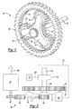
- a high pressure turbine section 15 drives compressor section 20 via first shaft 25.
- the gearbox 35 drives fan 45 via ring gear 50 as is known in the art to power an aircraft (not shown).
- a shaft brake 55 is attached to the shaft 40.
- the gearbox 35 which may be epicyclic, has rotative components including an input sun gear 60 mounted for rotation with the shaft 40, a plurality of planetary gears 65 mounted in a carrier 70, and an output ring gear 50 having teeth 75 that interact with the planetary gears 65.
- a power gear 80 is attached to the carrier 70 for rotation therewith.
- the gearbox 35 allows the fan 45 to rotate at different speeds than the speed of rotation of shaft 40 to optimize specific fuel consumption of the gas turbine engine 10.
- a gear train 85 is shown.
- the gear train 85 is driven by power gear 80 via gears 90 to provide rotative power to a power component 95 such as an electric generator, a hydraulic pump or the like, or other power or drive mechanisms that may be used in an aircraft and are contemplated for use herein.
- the power component 95 provides power 105, usually in the form of electricity or pumped fluid for use in the aircraft (now shown).
- a carrier brake 100 which may be a solenoid or other similar device to hold the carrier 70 against rotation, abuts the carrier 70.
- the power component 95 is designed to be used if the gas turbine engine 10 is not operating and powering a separate power source (not shown).
- a controller 110 sends a signal via line 115 to activate the carrier brake 100 and the carrier is therefore grounded or held against rotation.
- Shaft 40 rotates the sun gear 60 that rotates planetary gears 65 that rotate ring gear 50 which, in turn, rotates fan 45.
- the power component 95 is also grounded (i.e. producing no power) and machine stresses and wear on the power component 95 are minimized.
- the failed engine(s) fan 45 may windmill, or rotate due to the forward velocity of the aircraft (not shown). A significant amount of power could be drawn from the fan 45 in this scenario to drive the power component 95 such as an emergency generator and/or hydraulic pump.
- the controller 110 sends a signal via line 115 to disengage the carrier brake 100 to allow the carrier to rotate and a signal via line 120 to engage the shaft brake 55 to stop the shaft 40 and sun gear 60 from rotation.
- the sun gear 60 is grounded thereby allowing the rotating fan 45 to rotate the ring gear 50, which rotates the planetary gears 65 about the stationary sun gear 60 to rotate the carrier 70 and the power gear 80.
- the power gear 80 rotates the gears 90 to power the power component 95 to provide power 105 to the aircraft (not shown).
- the sun gear/ engine shaft By braking the sun gear/ engine shaft during an emergency parasitic losses are reduced; i.e. power can thus be extracted from the power component.
- the gas turbine engine 10 is inoperable, its mass and parasitic losses make the shaft 40 difficult to turn thereby providing a braking force on the sun gear reducing the need for a shaft brake 55.
- the mass and parasitic losses of the engine essentially provides a grounding force against rotation of the sun gear 60 thereby allowing a rotative force provided by fan 45 to power the power component 95 even if there is some rotation of the shaft 40.
- Grounding or ungrounding of the epicyclic differential members, by a carrier brake 100 and/or the shaft brake 55, could be accommodated via any number of clutching methods such as, for example band brakes, cone brakes, face clutches, etc.
Landscapes
- Engineering & Computer Science (AREA)
- Chemical & Material Sciences (AREA)
- Combustion & Propulsion (AREA)
- Mechanical Engineering (AREA)
- General Engineering & Computer Science (AREA)
- Retarders (AREA)
- Braking Arrangements (AREA)
Claims (7)
- Bläserantrieb für ein Luftfahrzeug, umfassend:ein Getriebe (35) umfassend:einen Planetenradträger (70);eine erste Bremse (100) zum Bremsen des Planetenradträgers gegen eine Rotation desselben;Planetenräder (65), die in dem Planetenradträger angebracht sind;ein Hohlrad (50), das derart angebracht ist, dass es die Planetenräder antreibt oder von diesen angetrieben wird;ein Sonnenrad (60), das derart angebracht ist, dass es die Planetenräder antreibt;eine zweite Bremse (100) zum Bremsen des Sonnenrads (60) gegen eine Rotation desselben; undeine Welle (40), die verbunden ist, um das Sonnenrad (60) anzutreiben;einen Maschinenbläser (45), der mit dem Hohlrad (50) verbunden und von diesem antreibbar ist; unddadurch gekennzeichnet, dass die erste Bremse (100) derart angeordnet ist, dass sie den Planetenradträger (70) bremst, um die Welle (40) das Sonnenrad antreiben zu lassen, um die Planetenräder anzutreiben, um das Hohlrad (50) anzutreiben, um den Maschinenbläser (45) anzutreiben; und dadurch, dass die zweite Bremse derart angeordnet ist, dass sie das Sonnenrad (60) bremst, wenn die erste Bremse (100) gelöst ist, um den Maschinenbläser (45) das Hohlrad (50) antreiben zu lassen, um die Planetenräder (65) anzutreiben, um den Planetenträger (70) anzutreiben.
- Bläserantrieb nach Anspruch 1, des Weiteren umfassend eine von dem Planetenradträger (70) angetriebene Leistungskomponente (95).
- Bläserantrieb nach Anspruch 1 oder 2, wobei das Getriebe (35) ein Differentialgetriebe ist.
- Maschine umfassend einen Bläserantrieb nach Anspruch 1, 2 oder 3, wobei die Maschine eine mit der Welle (40) verbundene Turbine aufweist.
- Verfahren zum selektiven Entkuppeln von Komponenten einer Turbobläser-Gasturbinenmaschine in einem Notfallzustand, wobei das Verfahren umfasst:Bereitstellen eines Getriebes (35) umfassend:einen Planetenradträger (70);eine erste Bremse (100) zum Bremsen des Planetenradträgers gegen eine Rotation von diesem;Planetenräder (65), die an den Planetenradträger angebracht sind;ein Hohlrad (50), das derart angebracht ist, dass es die Planetenräder antreibt oder von diesen angetrieben wird;ein Sonnenrad (60), das derart angebracht ist, dass es die Planetenräder antreibt;eine zweite Bremse (100) zum Bremsen des Sonnenrads (60) gegen eine Rotation von diesem; undeine Welle (40), die verbunden ist, um das Sonnenrad (60) anzutreiben;Verbinden eines Maschinenbläsers (45) mit dem Hohlrad (50); und gekennzeichnet durchwenn die Maschine in Betrieb ist, Bremsen des Planetenradträgers (70) mit der ersten Bremse (100), um es der Welle (40) zu erlauben, das Sonnenrad (60) anzutreiben, um über das Getriebe (35) das Hohlrad (50) anzutreiben, um den Maschinenbläser (45) anzutreiben,und wenn die Maschine nicht in Betrieb ist, Lösen des Bremsens des Planetenradträgers (70) und Bremsen des Sonnenrads (60) mit der zweiten Bremse (55), um es dem Maschinenbläser (45) zu erlauben, das Hohlrad (50) anzutreiben, um den Planetenradträger (70) anzutreiben.
- Verfahren nach Anspruch 5 des Weiteren umfassen;
Antreiben einer Leistungskomponente (95) durch den Planetenradträger (70), um Leistung abzunehmen wenn das Sonnenrad (60) gebremst ist. - Verfahren nach Anspruch 5 oder 6, wobei das Getriebe ein Differentialgetriebe ist.
Applications Claiming Priority (1)
| Application Number | Priority Date | Filing Date | Title |
|---|---|---|---|
| US12/835,802 US8425372B2 (en) | 2010-07-14 | 2010-07-14 | Geared turbofan emergency power |
Publications (3)
| Publication Number | Publication Date |
|---|---|
| EP2407644A2 EP2407644A2 (de) | 2012-01-18 |
| EP2407644A3 EP2407644A3 (de) | 2012-05-02 |
| EP2407644B1 true EP2407644B1 (de) | 2013-07-10 |
Family
ID=44352302
Family Applications (1)
| Application Number | Title | Priority Date | Filing Date |
|---|---|---|---|
| EP11173891.0A Active EP2407644B1 (de) | 2010-07-14 | 2011-07-13 | Turbofantriebwerk mit Getriebe |
Country Status (4)
| Country | Link |
|---|---|
| US (1) | US8425372B2 (de) |
| EP (1) | EP2407644B1 (de) |
| CN (1) | CN102338198B (de) |
| ES (1) | ES2421941T3 (de) |
Cited By (1)
| Publication number | Priority date | Publication date | Assignee | Title |
|---|---|---|---|---|
| KR102689318B1 (ko) * | 2022-04-06 | 2024-08-05 | 대한민국 | 유성기어세트를 사용한, 노면청소차량 엔진의 송풍팬에 대한 동력전달 제어장치 및 이를 사용한 동력 전달 제어방법 |
Families Citing this family (20)
| Publication number | Priority date | Publication date | Assignee | Title |
|---|---|---|---|---|
| US8876650B2 (en) * | 2012-03-30 | 2014-11-04 | Hamilton Sundstrand Corporation | Aircraft accessory drive multiple speed transmission |
| US9097237B2 (en) | 2013-03-14 | 2015-08-04 | Broadwind Energy, Inc. | Tools and methods for uptower maintenance |
| US10330017B2 (en) | 2013-07-12 | 2019-06-25 | United Technologies Corporation | Three spool geared turbofan with low pressure compressor drive gear system |
| WO2015031143A1 (en) * | 2013-08-29 | 2015-03-05 | United Technologies Corporation | Three spool geared turbofan with low pressure compressor drive gear system and mechanical controller |
| FR3034140B1 (fr) * | 2015-03-26 | 2018-09-07 | Safran Aircraft Engines | Turbomachine d’aeronef a reducteur planetaire ou epicycloidal |
| US10024405B2 (en) * | 2015-05-12 | 2018-07-17 | Hamilton Sundstrand Corporation | Dual redundant linear actuator |
| US20170126159A1 (en) * | 2015-10-29 | 2017-05-04 | Hamilton Sundstrand Corporation | Generation system with braking mechanism |
| US10006520B2 (en) * | 2016-08-31 | 2018-06-26 | General Electric Company | System for regulating stresses in ring gears |
| US20180073837A1 (en) * | 2016-09-12 | 2018-03-15 | Joel Bishara Bahu | Ballistic firearms container |
| US10648368B2 (en) * | 2017-03-29 | 2020-05-12 | Hamilton Sundstrand Corporation | Drive assembly for a gas turbine engine |
| GB201803038D0 (en) * | 2018-02-26 | 2018-04-11 | Rolls Royce Plc | Methods and apparatus for controlling at least a part of a start-up or re light process of a gas turbine engine |
| US11168616B2 (en) * | 2018-05-16 | 2021-11-09 | Raytheon Technologies Corporation | Hybrid electric fan with improved low pressure compressor |
| US11092082B2 (en) * | 2018-08-29 | 2021-08-17 | Pratt & Whitney Canada Corp. | Transmission for engine with two power inputs |
| US11261848B2 (en) | 2020-01-31 | 2022-03-01 | Renew Energy Maintenance, Llc | Field machining of wind turbine gearboxes |
| US12084195B2 (en) | 2021-04-29 | 2024-09-10 | Hamilton Sundstrand Corporation | Dual drive, dual clutch drive system for an aircraft accessory |
| US20220349349A1 (en) * | 2021-04-29 | 2022-11-03 | Hamilton Sundstrand Corporation | Single drive, dual clutch drive system for an aircraft accessory |
| US12398700B2 (en) * | 2022-07-14 | 2025-08-26 | Renew Energy Maintenance, Llc | Wind turbine bearing and method of lubrication |
| US12584446B2 (en) * | 2023-06-21 | 2026-03-24 | General Electric Company | Unidirectional fan brake for a gas turbine engine |
| US12292107B2 (en) | 2023-09-29 | 2025-05-06 | Rtx Corporation | Fluid damper for turbine engine geartrain assembly |
| US12565328B2 (en) * | 2024-07-15 | 2026-03-03 | Rtx Corporation | Differential driven open rotor with brake |
Family Cites Families (29)
| Publication number | Priority date | Publication date | Assignee | Title |
|---|---|---|---|---|
| US2348716A (en) | 1941-05-15 | 1944-05-16 | New Prod Corp | Change-speed gearing for aircraft propellers |
| US3136499A (en) | 1962-11-15 | 1964-06-09 | North American Aviation Inc | Aircraft power transmission system |
| US4075910A (en) | 1976-08-20 | 1978-02-28 | Caterpillar Tractor Co. | Overload safety device for gas turbine engines |
| US4912911A (en) | 1986-10-13 | 1990-04-03 | G.D. Engineering Pty. Limited | Machine for stretch wrapping of large reels of paper and other materials |
| US4979362A (en) | 1989-05-17 | 1990-12-25 | Sundstrand Corporation | Aircraft engine starting and emergency power generating system |
| FR2656055B1 (fr) | 1989-12-18 | 1994-04-29 | Lepelletier Pierre | Transmission automatique multivitesses pour vehicule automobile. |
| GB9606546D0 (en) | 1996-03-28 | 1996-06-05 | Rolls Royce Plc | Gas turbine engine system |
| GB9910393D0 (en) | 1999-05-05 | 1999-07-07 | Lucas Ind Plc | Electrical generator,an aero-engine including such a generator and an aircraft including such a generator |
| GB9910392D0 (en) | 1999-05-05 | 1999-07-07 | Lucas Ind Plc | Rotor for an electrical machine,and an electrical machine including such a rotor |
| JP3649058B2 (ja) * | 1999-10-08 | 2005-05-18 | トヨタ自動車株式会社 | 複数の原動機を備えた車両の制御装置 |
| DE10115984A1 (de) * | 2001-03-30 | 2002-10-10 | Zahnradfabrik Friedrichshafen | Antriebssystem für ein Kraftfahrzeug |
| US6503056B2 (en) | 2001-04-24 | 2003-01-07 | Honeywell International Inc. | Heating device and method for deployable ram air turbine |
| FR2826052B1 (fr) | 2001-06-19 | 2003-12-19 | Snecma Moteurs | Dispositif de secours au rallumage d'un turboreacteur en autorotation |
| US6676379B2 (en) | 2001-12-06 | 2004-01-13 | Honeywell International Inc. | Ram air turbine with speed increasing gearbox |
| US6769874B2 (en) | 2002-03-15 | 2004-08-03 | Hamilton Sundstrand | Permanent magnet alternator for a gas turbine engine |
| FR2878287B1 (fr) | 2004-11-25 | 2009-05-22 | Snecma Moteurs Sa | Turboreacteur double corps double flux avec generateur de courant electrique arriere |
| US20060137355A1 (en) * | 2004-12-27 | 2006-06-29 | Pratt & Whitney Canada Corp. | Fan driven emergency generator |
| US7169074B2 (en) * | 2005-01-24 | 2007-01-30 | General Motors Corporation | Electrically variable transmission having two planetary gear sets with one stationary member |
| US7588108B2 (en) * | 2005-03-16 | 2009-09-15 | Takayuki Miyao | Method of controlling vehicle driving system |
| US7805947B2 (en) * | 2005-05-19 | 2010-10-05 | Djamal Moulebhar | Aircraft with disengageable engine and auxiliary power unit components |
| US7307403B2 (en) | 2005-11-08 | 2007-12-11 | Honeywell International, Inc. | System and method for DC power generation from a reluctance machine |
| US7309974B2 (en) | 2005-11-08 | 2007-12-18 | Honeywell International, Inc. | System and method for AC power generation from a reluctance machine |
| DE102006006616A1 (de) * | 2006-02-14 | 2007-08-30 | Zf Friedrichshafen Ag | Mehrstufengetriebe |
| US7479080B2 (en) * | 2006-07-24 | 2009-01-20 | Gm Global Technology Operations, Inc. | Hybrid architecture incorporating three motor generators and brakes |
| US7849668B2 (en) | 2006-10-25 | 2010-12-14 | United Technologies Corporation | Rotor brake and windmilling lubrication system for geared turbofan engine |
| US7841163B2 (en) | 2006-11-13 | 2010-11-30 | Hamilton Sundstrand Corporation | Turbofan emergency generator |
| US7866947B2 (en) * | 2007-01-03 | 2011-01-11 | United Technologies Corporation | Turbine blade trip strip orientation |
| US7468561B2 (en) | 2007-03-27 | 2008-12-23 | General Electric Company | Integrated electrical power extraction for aircraft engines |
| US7854582B2 (en) * | 2007-05-08 | 2010-12-21 | Pratt & Whitney Canada Corp. | Operation of an aircraft engine after emergency shutdown |
-
2010
- 2010-07-14 US US12/835,802 patent/US8425372B2/en active Active
-
2011
- 2011-07-13 EP EP11173891.0A patent/EP2407644B1/de active Active
- 2011-07-13 ES ES11173891T patent/ES2421941T3/es active Active
- 2011-07-14 CN CN201110196784.6A patent/CN102338198B/zh active Active
Cited By (1)
| Publication number | Priority date | Publication date | Assignee | Title |
|---|---|---|---|---|
| KR102689318B1 (ko) * | 2022-04-06 | 2024-08-05 | 대한민국 | 유성기어세트를 사용한, 노면청소차량 엔진의 송풍팬에 대한 동력전달 제어장치 및 이를 사용한 동력 전달 제어방법 |
Also Published As
| Publication number | Publication date |
|---|---|
| CN102338198A (zh) | 2012-02-01 |
| US8425372B2 (en) | 2013-04-23 |
| CN102338198B (zh) | 2014-10-08 |
| ES2421941T3 (es) | 2013-09-06 |
| EP2407644A3 (de) | 2012-05-02 |
| US20120015776A1 (en) | 2012-01-19 |
| EP2407644A2 (de) | 2012-01-18 |
Similar Documents
| Publication | Publication Date | Title |
|---|---|---|
| EP2407644B1 (de) | Turbofantriebwerk mit Getriebe | |
| EP2066896B1 (de) | Gasturbinenmotor mit zwischengeschwindigkeitsverstärker | |
| JP5442707B2 (ja) | 可逆性電気機械を含むタービンエンジン | |
| CN109154255B (zh) | 压缩机系统 | |
| US10302018B2 (en) | Gas turbine engine geared compressor with first and second input rotors | |
| CA2612030C (en) | Variable coupling of turbofan engine spools via open differential or planetary gear set with torque coupling for power extraction and engine operability | |
| US5694765A (en) | Shaft power transfer in gas turbine engines with machines operable as generators or motors | |
| US20060137355A1 (en) | Fan driven emergency generator | |
| US20180223740A1 (en) | Multi-spool gas turbine engine | |
| JP5738398B2 (ja) | 可変速度ポンプを有する動力プラントライン | |
| GB2443743A (en) | Turbofan emergency generator | |
| EP3163032B1 (de) | System zur erzeugungs elektrischer energie mit bremsmechanismus sowie verfahren | |
| CN110873156A (zh) | 用于具有两个功率输入的发动机的变速器 | |
| CN120752424A (zh) | 航空推进系统 | |
| GB2440747A (en) | Hydrodynamic coupling with movable turbine for engine power take off | |
| GB2472016A (en) | A gear train for contra-rotating propeller gas turbine engine |
Legal Events
| Date | Code | Title | Description |
|---|---|---|---|
| AK | Designated contracting states |
Kind code of ref document: A2 Designated state(s): AL AT BE BG CH CY CZ DE DK EE ES FI FR GB GR HR HU IE IS IT LI LT LU LV MC MK MT NL NO PL PT RO RS SE SI SK SM TR |
|
| AX | Request for extension of the european patent |
Extension state: BA ME |
|
| PUAI | Public reference made under article 153(3) epc to a published international application that has entered the european phase |
Free format text: ORIGINAL CODE: 0009012 |
|
| PUAL | Search report despatched |
Free format text: ORIGINAL CODE: 0009013 |
|
| AK | Designated contracting states |
Kind code of ref document: A3 Designated state(s): AL AT BE BG CH CY CZ DE DK EE ES FI FR GB GR HR HU IE IS IT LI LT LU LV MC MK MT NL NO PL PT RO RS SE SI SK SM TR |
|
| AX | Request for extension of the european patent |
Extension state: BA ME |
|
| RIC1 | Information provided on ipc code assigned before grant |
Ipc: F01D 21/00 20060101AFI20120327BHEP Ipc: F02C 7/36 20060101ALI20120327BHEP Ipc: F02K 3/06 20060101ALI20120327BHEP |
|
| 17P | Request for examination filed |
Effective date: 20121102 |
|
| GRAP | Despatch of communication of intention to grant a patent |
Free format text: ORIGINAL CODE: EPIDOSNIGR1 |
|
| GRAS | Grant fee paid |
Free format text: ORIGINAL CODE: EPIDOSNIGR3 |
|
| GRAA | (expected) grant |
Free format text: ORIGINAL CODE: 0009210 |
|
| AK | Designated contracting states |
Kind code of ref document: B1 Designated state(s): AL AT BE BG CH CY CZ DE DK EE ES FI FR GB GR HR HU IE IS IT LI LT LU LV MC MK MT NL NO PL PT RO RS SE SI SK SM TR |
|
| REG | Reference to a national code |
Ref country code: GB Ref legal event code: FG4D |
|
| REG | Reference to a national code |
Ref country code: AT Ref legal event code: REF Ref document number: 621093 Country of ref document: AT Kind code of ref document: T Effective date: 20130715 Ref country code: CH Ref legal event code: EP |
|
| REG | Reference to a national code |
Ref country code: IE Ref legal event code: FG4D |
|
| REG | Reference to a national code |
Ref country code: DE Ref legal event code: R096 Ref document number: 602011002264 Country of ref document: DE Effective date: 20130905 |
|
| PG25 | Lapsed in a contracting state [announced via postgrant information from national office to epo] |
Ref country code: SI Free format text: LAPSE BECAUSE OF FAILURE TO SUBMIT A TRANSLATION OF THE DESCRIPTION OR TO PAY THE FEE WITHIN THE PRESCRIBED TIME-LIMIT Effective date: 20130710 |
|
| REG | Reference to a national code |
Ref country code: AT Ref legal event code: MK05 Ref document number: 621093 Country of ref document: AT Kind code of ref document: T Effective date: 20130710 |
|
| REG | Reference to a national code |
Ref country code: NL Ref legal event code: VDEP Effective date: 20130710 |
|
| REG | Reference to a national code |
Ref country code: LT Ref legal event code: MG4D |
|
| PG25 | Lapsed in a contracting state [announced via postgrant information from national office to epo] |
Ref country code: BE Free format text: LAPSE BECAUSE OF FAILURE TO SUBMIT A TRANSLATION OF THE DESCRIPTION OR TO PAY THE FEE WITHIN THE PRESCRIBED TIME-LIMIT Effective date: 20130710 Ref country code: NO Free format text: LAPSE BECAUSE OF FAILURE TO SUBMIT A TRANSLATION OF THE DESCRIPTION OR TO PAY THE FEE WITHIN THE PRESCRIBED TIME-LIMIT Effective date: 20131010 Ref country code: IS Free format text: LAPSE BECAUSE OF FAILURE TO SUBMIT A TRANSLATION OF THE DESCRIPTION OR TO PAY THE FEE WITHIN THE PRESCRIBED TIME-LIMIT Effective date: 20131110 Ref country code: LT Free format text: LAPSE BECAUSE OF FAILURE TO SUBMIT A TRANSLATION OF THE DESCRIPTION OR TO PAY THE FEE WITHIN THE PRESCRIBED TIME-LIMIT Effective date: 20130710 Ref country code: AT Free format text: LAPSE BECAUSE OF FAILURE TO SUBMIT A TRANSLATION OF THE DESCRIPTION OR TO PAY THE FEE WITHIN THE PRESCRIBED TIME-LIMIT Effective date: 20130710 Ref country code: CY Free format text: LAPSE BECAUSE OF FAILURE TO SUBMIT A TRANSLATION OF THE DESCRIPTION OR TO PAY THE FEE WITHIN THE PRESCRIBED TIME-LIMIT Effective date: 20130807 Ref country code: HR Free format text: LAPSE BECAUSE OF FAILURE TO SUBMIT A TRANSLATION OF THE DESCRIPTION OR TO PAY THE FEE WITHIN THE PRESCRIBED TIME-LIMIT Effective date: 20130710 Ref country code: SE Free format text: LAPSE BECAUSE OF FAILURE TO SUBMIT A TRANSLATION OF THE DESCRIPTION OR TO PAY THE FEE WITHIN THE PRESCRIBED TIME-LIMIT Effective date: 20130710 Ref country code: PT Free format text: LAPSE BECAUSE OF FAILURE TO SUBMIT A TRANSLATION OF THE DESCRIPTION OR TO PAY THE FEE WITHIN THE PRESCRIBED TIME-LIMIT Effective date: 20131111 |
|
| PG25 | Lapsed in a contracting state [announced via postgrant information from national office to epo] |
Ref country code: LV Free format text: LAPSE BECAUSE OF FAILURE TO SUBMIT A TRANSLATION OF THE DESCRIPTION OR TO PAY THE FEE WITHIN THE PRESCRIBED TIME-LIMIT Effective date: 20130710 Ref country code: NL Free format text: LAPSE BECAUSE OF FAILURE TO SUBMIT A TRANSLATION OF THE DESCRIPTION OR TO PAY THE FEE WITHIN THE PRESCRIBED TIME-LIMIT Effective date: 20130710 Ref country code: PL Free format text: LAPSE BECAUSE OF FAILURE TO SUBMIT A TRANSLATION OF THE DESCRIPTION OR TO PAY THE FEE WITHIN THE PRESCRIBED TIME-LIMIT Effective date: 20130710 Ref country code: GR Free format text: LAPSE BECAUSE OF FAILURE TO SUBMIT A TRANSLATION OF THE DESCRIPTION OR TO PAY THE FEE WITHIN THE PRESCRIBED TIME-LIMIT Effective date: 20131011 Ref country code: FI Free format text: LAPSE BECAUSE OF FAILURE TO SUBMIT A TRANSLATION OF THE DESCRIPTION OR TO PAY THE FEE WITHIN THE PRESCRIBED TIME-LIMIT Effective date: 20130710 |
|
| PG25 | Lapsed in a contracting state [announced via postgrant information from national office to epo] |
Ref country code: CY Free format text: LAPSE BECAUSE OF FAILURE TO SUBMIT A TRANSLATION OF THE DESCRIPTION OR TO PAY THE FEE WITHIN THE PRESCRIBED TIME-LIMIT Effective date: 20130710 |
|
| REG | Reference to a national code |
Ref country code: IE Ref legal event code: MM4A |
|
| PG25 | Lapsed in a contracting state [announced via postgrant information from national office to epo] |
Ref country code: EE Free format text: LAPSE BECAUSE OF FAILURE TO SUBMIT A TRANSLATION OF THE DESCRIPTION OR TO PAY THE FEE WITHIN THE PRESCRIBED TIME-LIMIT Effective date: 20130710 Ref country code: RO Free format text: LAPSE BECAUSE OF FAILURE TO SUBMIT A TRANSLATION OF THE DESCRIPTION OR TO PAY THE FEE WITHIN THE PRESCRIBED TIME-LIMIT Effective date: 20130710 Ref country code: DK Free format text: LAPSE BECAUSE OF FAILURE TO SUBMIT A TRANSLATION OF THE DESCRIPTION OR TO PAY THE FEE WITHIN THE PRESCRIBED TIME-LIMIT Effective date: 20130710 Ref country code: SK Free format text: LAPSE BECAUSE OF FAILURE TO SUBMIT A TRANSLATION OF THE DESCRIPTION OR TO PAY THE FEE WITHIN THE PRESCRIBED TIME-LIMIT Effective date: 20130710 Ref country code: MC Free format text: LAPSE BECAUSE OF FAILURE TO SUBMIT A TRANSLATION OF THE DESCRIPTION OR TO PAY THE FEE WITHIN THE PRESCRIBED TIME-LIMIT Effective date: 20130710 Ref country code: CZ Free format text: LAPSE BECAUSE OF FAILURE TO SUBMIT A TRANSLATION OF THE DESCRIPTION OR TO PAY THE FEE WITHIN THE PRESCRIBED TIME-LIMIT Effective date: 20130710 |
|
| PLBE | No opposition filed within time limit |
Free format text: ORIGINAL CODE: 0009261 |
|
| STAA | Information on the status of an ep patent application or granted ep patent |
Free format text: STATUS: NO OPPOSITION FILED WITHIN TIME LIMIT |
|
| PG25 | Lapsed in a contracting state [announced via postgrant information from national office to epo] |
Ref country code: IT Free format text: LAPSE BECAUSE OF FAILURE TO SUBMIT A TRANSLATION OF THE DESCRIPTION OR TO PAY THE FEE WITHIN THE PRESCRIBED TIME-LIMIT Effective date: 20130710 |
|
| 26N | No opposition filed |
Effective date: 20140411 |
|
| REG | Reference to a national code |
Ref country code: DE Ref legal event code: R097 Ref document number: 602011002264 Country of ref document: DE Effective date: 20140411 |
|
| PG25 | Lapsed in a contracting state [announced via postgrant information from national office to epo] |
Ref country code: IE Free format text: LAPSE BECAUSE OF NON-PAYMENT OF DUE FEES Effective date: 20130713 |
|
| REG | Reference to a national code |
Ref country code: CH Ref legal event code: PL |
|
| PG25 | Lapsed in a contracting state [announced via postgrant information from national office to epo] |
Ref country code: LI Free format text: LAPSE BECAUSE OF NON-PAYMENT OF DUE FEES Effective date: 20140731 Ref country code: CH Free format text: LAPSE BECAUSE OF NON-PAYMENT OF DUE FEES Effective date: 20140731 |
|
| PG25 | Lapsed in a contracting state [announced via postgrant information from national office to epo] |
Ref country code: SM Free format text: LAPSE BECAUSE OF FAILURE TO SUBMIT A TRANSLATION OF THE DESCRIPTION OR TO PAY THE FEE WITHIN THE PRESCRIBED TIME-LIMIT Effective date: 20130710 |
|
| PG25 | Lapsed in a contracting state [announced via postgrant information from national office to epo] |
Ref country code: TR Free format text: LAPSE BECAUSE OF FAILURE TO SUBMIT A TRANSLATION OF THE DESCRIPTION OR TO PAY THE FEE WITHIN THE PRESCRIBED TIME-LIMIT Effective date: 20130710 Ref country code: MT Free format text: LAPSE BECAUSE OF FAILURE TO SUBMIT A TRANSLATION OF THE DESCRIPTION OR TO PAY THE FEE WITHIN THE PRESCRIBED TIME-LIMIT Effective date: 20130710 |
|
| PG25 | Lapsed in a contracting state [announced via postgrant information from national office to epo] |
Ref country code: RS Free format text: LAPSE BECAUSE OF FAILURE TO SUBMIT A TRANSLATION OF THE DESCRIPTION OR TO PAY THE FEE WITHIN THE PRESCRIBED TIME-LIMIT Effective date: 20131010 Ref country code: LU Free format text: LAPSE BECAUSE OF NON-PAYMENT OF DUE FEES Effective date: 20130713 Ref country code: MK Free format text: LAPSE BECAUSE OF FAILURE TO SUBMIT A TRANSLATION OF THE DESCRIPTION OR TO PAY THE FEE WITHIN THE PRESCRIBED TIME-LIMIT Effective date: 20130710 Ref country code: HU Free format text: LAPSE BECAUSE OF FAILURE TO SUBMIT A TRANSLATION OF THE DESCRIPTION OR TO PAY THE FEE WITHIN THE PRESCRIBED TIME-LIMIT; INVALID AB INITIO Effective date: 20110713 Ref country code: BG Free format text: LAPSE BECAUSE OF FAILURE TO SUBMIT A TRANSLATION OF THE DESCRIPTION OR TO PAY THE FEE WITHIN THE PRESCRIBED TIME-LIMIT Effective date: 20130710 |
|
| GBPC | Gb: european patent ceased through non-payment of renewal fee |
Effective date: 20150713 |
|
| PG25 | Lapsed in a contracting state [announced via postgrant information from national office to epo] |
Ref country code: GB Free format text: LAPSE BECAUSE OF NON-PAYMENT OF DUE FEES Effective date: 20150713 |
|
| REG | Reference to a national code |
Ref country code: FR Ref legal event code: PLFP Year of fee payment: 6 |
|
| REG | Reference to a national code |
Ref country code: FR Ref legal event code: PLFP Year of fee payment: 7 |
|
| REG | Reference to a national code |
Ref country code: DE Ref legal event code: R082 Ref document number: 602011002264 Country of ref document: DE Representative=s name: SCHMITT-NILSON SCHRAUD WAIBEL WOHLFROM PATENTA, DE |
|
| REG | Reference to a national code |
Ref country code: FR Ref legal event code: PLFP Year of fee payment: 8 |
|
| PG25 | Lapsed in a contracting state [announced via postgrant information from national office to epo] |
Ref country code: AL Free format text: LAPSE BECAUSE OF FAILURE TO SUBMIT A TRANSLATION OF THE DESCRIPTION OR TO PAY THE FEE WITHIN THE PRESCRIBED TIME-LIMIT Effective date: 20130710 |
|
| P01 | Opt-out of the competence of the unified patent court (upc) registered |
Effective date: 20230522 |
|
| PGFP | Annual fee paid to national office [announced via postgrant information from national office to epo] |
Ref country code: FR Payment date: 20250620 Year of fee payment: 15 |
|
| PGFP | Annual fee paid to national office [announced via postgrant information from national office to epo] |
Ref country code: ES Payment date: 20250801 Year of fee payment: 15 |
|
| PGFP | Annual fee paid to national office [announced via postgrant information from national office to epo] |
Ref country code: DE Payment date: 20250620 Year of fee payment: 15 |