EP2405289A1 - Coating removal unit and optical fiber coating removal apparatus - Google Patents
Coating removal unit and optical fiber coating removal apparatus Download PDFInfo
- Publication number
- EP2405289A1 EP2405289A1 EP10748511A EP10748511A EP2405289A1 EP 2405289 A1 EP2405289 A1 EP 2405289A1 EP 10748511 A EP10748511 A EP 10748511A EP 10748511 A EP10748511 A EP 10748511A EP 2405289 A1 EP2405289 A1 EP 2405289A1
- Authority
- EP
- European Patent Office
- Prior art keywords
- blade
- optical fiber
- sheath
- guide body
- sheath removing
- Prior art date
- Legal status (The legal status is an assumption and is not a legal conclusion. Google has not performed a legal analysis and makes no representation as to the accuracy of the status listed.)
- Granted
Links
Images



Classifications
-
- G—PHYSICS
- G02—OPTICS
- G02B—OPTICAL ELEMENTS, SYSTEMS OR APPARATUS
- G02B6/00—Light guides; Structural details of arrangements comprising light guides and other optical elements, e.g. couplings
- G02B6/24—Coupling light guides
- G02B6/245—Removing protective coverings of light guides before coupling
-
- H—ELECTRICITY
- H01—ELECTRIC ELEMENTS
- H01B—CABLES; CONDUCTORS; INSULATORS; SELECTION OF MATERIALS FOR THEIR CONDUCTIVE, INSULATING OR DIELECTRIC PROPERTIES
- H01B7/00—Insulated conductors or cables characterised by their form
- H01B7/38—Insulated conductors or cables characterised by their form with arrangements for facilitating removal of insulation
Definitions
- the present invention relates to a sheath removing unit and an optical fiber-sheath removing device that remove a sheath of a sheathed optical fiber, such as an optical fiber strand and an optical fiber core.
- FIGS. 10 to 12 An example of a sheath removing unit in the related art is shown in FIGS. 10 to 12 as a tool that removes the sheath.
- the sheath removing unit 20 is a unit that removes a sheath 21b of a sheathed optical fiber 21, and includes a sheath removing blade 28.
- the sheath removing blade 28 includes a blade pressing plate 22, a semicircular blade 23, a flat blade 24, and a blade receiving plate 25.
- the blade pressing plate, the semicircular blade, the flat blade, and the blade receiving plate are laminated in this order and integrated.
- a notch 22a in which the sheathed optical fiber 21 can be received is formed at the blade pressing plate 22.
- the semicircular blade 23 includes a semicircular blade portion 23a.
- the inner diameter of the blade portion 23a is smaller than the outer diameter of the sheath 21b of the sheathed optical fiber 21 and larger than the outer diameter of a bare optical fiber 21a of the sheathed optical fiber 21.
- the blade receiving plate 25 includes a pressing portion 27 and a base portion 26 including a V-shaped notch 26a in which the sheathed optical fiber 21 is received.
- the sheath removing unit 20 is made to move in the direction of an arrow in FIG. 11 .
- the blade portion 23a of the semicircular blade 23 removes the sheath 21b of the sheathed optical fiber 21.
- optical fiber-sheath removing devices including the above-mentioned sheath removing unit are generally manual optical fiber-sheath removing devices.
- an optical fiber received in the optical fiber amplifier may have a small radius of curvature and a tendency to bend in many cases.
- the sheathed optical fiber 21 When a sheathed optical fiber 21 having this tendency to bend is treated in the sheath removing unit 20, the sheathed optical fiber 21 might not be positioned at the notches 22a and 26a and a positional deviation might occur.
- an object of the invention is to provide a sheath removing unit that is suitable for specifications of an automatic device or the like and includes a guide capable of accurately positioning an optical fiber, and an optical fiber-sheath removing device including the sheath removing unit.
- an object of the invention is to provide a sheath removing unit and an optical fiber-sheath removing device that can prevent breakage of a bare optical fiber without positional deviation of an optical fiber at the time of the removal of a sheath even when being applied to a sheathed optical fiber having a tendency to bend.
- the optical fiber guide is disposed so as to be superimposed on the sheath removing blade.
- the sheath removing unit removes a sheath of a sheathed optical fiber.
- the optical fiber guide includes a first guide body and a second guide body that are disposed so as to face each other.
- the first guide body includes a first protruding portion that is disposed so as to be superimposed on one blade body of the blade bodies and protrudes from the opposite surface of the one blade body toward the other blade body when seen in plan view.
- the second guide body includes a second protruding portion that is disposed so as to be superimposed on the other blade body and protrudes from the opposite surface of the other blade body toward the one blade body when seen in plan view.
- a lower inclined portion which is inclined outward toward a protruding direction of the first protruding portion, is formed on a surface of the first protruding portion facing the second guide body.
- An upper inclined portion which is inclined outward toward a protruding direction of the second protruding portion, is formed on a surface of the second protruding portion facing the first guide body.
- the lower inclined portion is formed at the first protruding portion of the first guide body of the optical fiber guide and the upper inclined portion is formed at the second protruding portion of the second guide body.
- the structure described in (1) is easily applied to optical fiber-sheath removing devices having different specifications.
- the sheath removing unit 10A removes a sheath 21b of a sheathed optical fiber 21 from a bare optical fiber 21a.
- the sheath removing unit 10A includes a sheath removing blade 1, an optical fiber guide 2, and a positioning plate 3.
- the sheath removing blade 1, the optical fiber guide 2, and the positioning plate 3 are disposed in this order in a thickness direction thereof.
- the sheath removing blade 1, the optical fiber guide 2, and the positioning plate 3 may be disposed so as to be separated from each other and may be disposed so as to be laminated on each other.
- the sheathed optical fiber 21 is, for example, an optical fiber core or an optical fiber strand.
- the sheath removing blade 1 includes a pair of substantially rectangular blade bodies 4 and 4 that is formed in the shape of a thin plate.
- one blade body 4 is denoted by reference numeral 4A and the other blade body 4 is denoted by reference numeral 4B.
- blade bodies 4 (4A and 4B) are disposed in substantially the same plane so that opposite surfaces (opposite edge portions) 4a and 4a face each other.
- a concave blade portion 5 having a semicircular shape is formed substantially in the middle of each of the opposite edge portions 4a and 4a.
- the concave blade portions 5 and 5 are formed so that the diameter of the first opening is smaller than the outer diameter of the sheath 21b of the sheathed optical fiber 21 and is larger than the outer diameter of the bare optical fiber 21a.
- the concave blade portions 5 and 5 remove only the sheath 21b without damaging the bare optical fiber 21a.
- Positioning mechanisms 4b and 4c may be formed at the straight portions 6 of the blade bodies 4 (4A and 4B) as shown in FIG. 5 .
- the positioning mechanisms 4b and 4c position the blade bodies 4A and 4B (the sheath removing unit 10A) in a height direction.
- projecting portions 4b that are formed at one blade body 4A and recessed portions 4c that are formed at the other blade body 4B so as to be fitted to the projecting portions 48 are used as the positioning mechanisms.
- the projecting portions 4b and the recessed portions 4c are fitted to each other, so that the blade bodies 4 (4A and 4B) are positioned in the height direction.
- a bare optical fiber 21a from which a sheath 21b has been removed is more stably provided.
- FIG. 5 has shown a case where the proj ecting portions 4b are formed at one blade body 4A and the recessed portions 4c are formed at the other blade body 4B.
- the projecting portion 4b may be formed at the upper portion of one blade body 4A and the recessed portion 4c may be formed at the lower portion of the blade body 4A.
- the number of the projecting portions 4b and the recessed portions 4c is not particularly limited.
- the sheathed optical fiber 21, which is used in the invention, is not particularly limited.
- the sheathed optical fiber is a single mode fiber (based on ITU-T G652 B), and Fujikura FutureGuide(R)-SM and the like may be used as the sheathed optical fiber.
- the optical fiber guide 2 includes a pair of guide bodies 7 and 8 (a first guide body 7 and a second guide body 8) formed in the shape of a thin plate.
- the pair of guide bodies 7 and 8 is disposed adjacent to the sheath removing blade 1 in the longitudinal direction of the sheathed optical fiber 21.
- the sheath removing blade 1 is disposed parallel to the pair of guide bodies 7 and 8.
- the first guide body 7 and the second guide body 8 are disposed in the same plane so as to face each other.
- the opposite surfaces of the first guide body 7 and the second guide body 8 facing each other are referred to as opposite edge portions 7a and 8a (inner edges).
- the opposite edge portion 8a of the second guide body has a shape corresponding to the shape of the opposite edge portion 7a of the first guide body 7.
- upper and lower edge portions 7b and 7c of the first guide body 7 are formed parallel to each other.
- the opposite edge portion 7a of the first guide body 7 includes an upper inclined portion 11 that descends from the upper edge portion 7b at a predetermined angle from one end 7d of the first guide body 7 toward the other end 7e thereof, a middle portion 12 that extends from the lower end of the upper inclined portion 11 so as to be parallel to the upper edge portion 7b, and a lower inclined portion 13 that descends from the middle portion 12 at a predetermined angle.
- an inclination angle ⁇ 1 of the lower inclined portion 13 with respect to the lower edge portion 7c is preferably in the range of 15 to 45° and more preferably in the range of 20 to 35°.
- the lower inclined portion 13 of the first guide body 7 be formed at a position corresponding to the lower straight portion 6 of the sheath removing blade 1 as shown in FIG. 2 .
- the position of the middle portion 12 of the first guide body 7 be a position corresponding to the vicinity of the lower end of the concave blade portion 5 of one blade body 4A.
- the position of the middle portion 12 of the first guide body 7 be a position corresponding to the lower end of the concave blade portion 5 or a position slightly below this position.
- the sheathed optical fiber 21 is guided by the lower inclined portion 13 of the first guide body 7 so as to be introduced to the concave blade portion 5 of the sheath removing blade 1.
- the first protruding portion 34 protrudes along the middle portion 12 toward the other blade body 4B.
- the lower inclined portion 13 is inclined so as to gradually descend toward the protruding direction of the first protruding portion 34 (that is, toward the outside).
- upper and lower edge portions 8b and 8c of the second guide body 8 are formed parallel to each other.
- the opposite edge portion 8a of the second guide body 8 includes an upper inclined portion 14 that descends at a predetermined angle from one end 8d toward the other end 8e, a middle portion 15 that extends from the lower end of the upper inclined portion 14 so as to be parallel to the upper edge portion 8b, and a lower inclined portion 16 that descends from the middle portion 15 at a predetermined angle.
- the opposite edge portion 8a of the second guide body 8 has a shape corresponding to the shape of the opposite edge portion 7a of the first guide body 7.
- the upper inclined portion 14 of the second guide body 8 is formed substantially parallel to the upper inclined portion 11 of the first guide body 7.
- the middle portion 15 of the second guide body 8 is formed substantially parallel to the middle portion 12 of the first guide body 7.
- the lower inclined portion 16 of the second guide body 8 is formed substantially parallel to the lower inclined portion 13 of the first guide body 7.
- the upper inclined portion 14, the middle portion 15, and the lower inclined portion 16 of the second guide body 8 are formed so as to face the upper inclined portion 11, the middle portion 12, and the lower inclined portion 13 of the first guide body 7, respectively, when the opposite edge portion 7a of the first guide body 7 and the opposite edge portion 8a of the second guide body 8 face each other.
- an inclination angle ⁇ 2 of the upper inclined portion 14 of the second guide body 8 with respect to the upper edge portion 8b is preferably in the range of 15 to 45° and more preferably in the range of 20 to 35°, for the same reason as the inclination angle ⁇ 1 of the lower inclined portion 13 of the first guide body 7.
- the upper inclined portion 14 of the second guide body 8 be formed at a position corresponding to the upper straight portion 6 of the sheath removing blade 1 as shown in FIG. 2 .
- the position of the middle portion 15 of the second guide body 8 be a position corresponding to the vicinity of the upper end of the concave blade portion 5 of the other blade body 4B.
- the position of the middle portion 15 of the second guide body 8 be a position corresponding to the upper end of the concave blade portion 5 or a position slightly above this position.
- the sheathed optical fiber 21 is guided by the upper inclined portion 14 of the second guide body 8 so as to be introduced to the concave blade portion 5 of the sheath removing blade 1.
- the difference between the height of the middle portion 12 of the first guide body 7 and the height of the middle portion 15 of the second guide body 8 be substantially equal to the outer diameter of the sheathed optical fiber 21 or be slightly larger than the outer diameter of the sheathed optical fiber 21.
- a portion of the second guide body 8 which includes the middle portion 15 and the upper inclined portion 14, forms a second protruding portion 36 that protrudes from the upper portion of a main body portion 35 (a portion including the lower inclined portion 16) to the left side in FIG. 2 .
- the second protruding portion 36 protrudes along the middle portion 15 toward one blade body 4A.
- the upper inclined portion 14 is inclined so as to gradually ascend toward the protruding direction of the second protruding portion 36 (that is, toward the outside).
- the positioning plate 3 leads the sheathed optical fiber 21 into a space between the first guide body 7 and the second guide body 8 of the optical fiber guide 2, particularly, the range R shown in FIG. 2 , and positions the sheathed optical fiber 21.
- This positioning plate 3 includes a pair of positioning portions 18 (one positioning portion 18A and the other positioning portion 18B) as shown in FIG. 1 , and these positioning portions are disposed so as to face each other.
- opposite edge portions 18a the opposite surfaces of these positioning portions 18 (18A and 18B) facing each other are referred to as opposite edge portions 18a.
- These positioning portions 18 (18A and 18B) are provided parallel to the optical fiber guide 2 in the longitudinal direction of the sheathed optical fiber 21.
- the concave receiving portions 19 and 19 form a circular opening (second opening).
- the concave receiving portions 19 and 19 are formed so that the diameter of the second opening is slightly larger than the outer diameter of the sheathed optical fiber 21.
- the concave receiving portions 19 and 19 have a size where the sheathed optical fiber 21 is received without inconvenience.
- the concave receiving portions 19 and 19 are formed at the positions corresponding to the concave blade portions 5 of the sheath removing blade 1.
- Positioning mechanisms 18b and 18c may be formed at the opposite edge portions 18a and 18a of the positioning portions 18 (18A and 18B) as shown in FIG. 6 .
- the positioning mechanisms 18b and 18c position the positioning plate 3 (the sheath removing unit 10A) in the thickness direction of the positioning plate.
- recessed portions 18b that are formed at one positioning portion 18A and protruding portions 18c that are formed at the other positioning portion 18B so as to be fitted to the recessed portions 18b are used as the positioning mechanisms.
- the recessed portion 18b and the protruding portion 18c are fitted to each other and the positioning plate 3 is positioned in the thickness direction thereof.
- the concave blade portion 5 of one blade body 4A and the concave blade portion 5 of the other blade body 4B come into contact with the sheath 21b of the sheathed optical fiber 21 without deviating from each other in the thickness direction of the blade body, so that the sheath 21b is uniformly removed.
- the sheath removing unit 10A has a basic structure that includes the sheath removing blade 1 and the optical fiber guide 2 (that is, a structure that does not include the positioning plate 3), it is possible to guide the sheathed optical fiber 21, which has a tendency to bend, to the concave blade portions 5 that are formed at the center of the sheath removing blade 1 and to remove the sheath 21b.
- One blade body 4A, the first guide body 7, and one positioning portion 18A of the sheath removing unit 10A according to this embodiment integrally operate as a first unit body 31.
- the other blade body 4B, the second guide body 8, and the other positioning portion 18B integrally operate as a second unit body 32.
- One or both of the first unit body 31 and the second unit body 32 can be moved by, for example, a moving mechanism (not shown) so as to approach each other or so as to be separated from each other.
- the first protruding portion 34 of the first guide body 7 of the first unit body 31 protrudes from the opposite edge portion 4a of one blade body 4A toward the second unit body 32 as shown in FIG. 2 .
- the second protruding portion 36 of the second guide body 8 of the second unit body 32 protrudes from the opposite edge portion 4a of the other blade body 4B toward the first unit body 31.
- the first unit body 31 and the second unit body 32 are made to be separated from each other and a sheathed optical fiber 21 is disposed between the first unit body and the second unit body.
- the height of the sheathed optical fiber 21 corresponds to a position corresponding to the upper inclined portion 14 of the second guide body 8.
- the sheathed optical fiber 21 is pressed by the upper inclined portion 14 of the second unit body 32 and is moved downward along the straight portion 6 of the blade body 4 of the first unit body 31.
- the sheathed optical fiber 21 When seen in plan view in the state shown in FIG. 3 , the sheathed optical fiber 21 is positioned in a space 37 that is surrounded by the first protruding portion 34, one blade body 4A, the other blade body 4B, and the second protruding portion 36.
- Both the first unit body 31 and the second unit body 32 may be moved so as to approach each other, and one of the first unit body and the second unit body may be moved so as to approach the other thereof.
- the moving direction of the first or second unit body is substantially the same as the protruding direction of the first protruding portion 34 or the second protruding portion 36.
- the sheathed optical fiber 21 is pressed by the upper inclined portion 14 of the second unit body 32 and is further moved downward.
- the vertical movement of the sheathed optical fiber 21 is regulated between the middle portion 12 of the first unit body 31 (first guide body 7) and the middle portion 15 of the second unit body 32 (second guide body 8).
- the sheathed optical fiber 21 is led into the concave receiving portions 19 and 19 of the positioning plate 3 by the movement of the first unit body 31 and the second unit body 32 and is positioned in the concave receiving portions.
- the sheathed optical fiber 21 is moved relative to the sheath removing unit 10 in the thickness direction of the sheath removing blade 1, that is, in the direction perpendicular to the plane of FIGS. 2 to 4 .
- the sheathed optical fiber 21 is disposed at a low position in the space 37, for example, at the height corresponding to the lower inclined portion 13 of the first guide body 7, the sheathed optical fiber 21 is moved upward by the lower inclined portion 13 and led into the concave blade portion 5.
- the sheathed optical fiber 21 is led into the concave blade portion 5 and the concave receiving portion 19 by the upper inclined portion 14 of the second guide body 8 or the lower inclined portion 13 of the first guide body 7 in the space 37 that is surrounded by the first protruding portion 34, the one blade body 4A, the other blade body 4B, and the second protruding portion 36 shown in FIG. 3 .
- the sheathed optical fiber 21 is led into the concave blade portion 5 and the concave receiving portion 19 by the first guide body 7 or the second guide body 8. As a result, the sheath 21b of the sheathed optical fiber is removed at an exact position.
- sheath removing unit 10A is easily applied to optical fiber-sheath removing devices having different specifications.
- the sheath removing unit 10A according to this embodiment is mounted instead of a sheath removing blade that is used in an existing optical fiber-sheath removing device, the above-mentioned advantage is obtained.
- FIG. 7 is a front view of a sheath removing unit 10 (10B) according to a second embodiment of the invention.
- a sheath removing unit 10B according to this embodiment is different from the sheath removing unit 10A according to the first embodiment in that a liquid inlet 41 is formed at one positioning plate 18A and a gas inlet 43 is formed at the other positioning plate 18B.
- the sheath removing unit according to this embodiment is different from the sheath removing unit according to the first embodiment in that an upper edge portion 7b of a first guide body 7 is formed at the position corresponding to the vicinity of the upper end of one positioning portion 18A and a lower edge portion 8c of a second guide body 8 is formed at the position corresponding to the vicinity of the lower end of the other positioning portion 18B.
- Both the liquid inlet 41 and the gas inlet 43 have been formed in this embodiment, but only one of the liquid inlet and the gas inlet may be formed at the positioning portions 18 (18A and 18B).
- a sheath removing blade 1 is not shown in FIGS. 7 and 8 , but the structure of the sheath removing blade 1 is the same as that of the sheath removing blade of the first embodiment.
- the gas inlet 43 is formed at the other positioning plate 18B so as to be opened to a space 42 between the first guide body 7 and the second guide body 8 as shown in FIG. 8 when the first unit body 31 and the second unit body 32 are combined with each other.
- Gas such as air is introduced to the space 42 from the gas inlet 43.
- FIG. 8 is a view showing a state where the sheathed optical fiber 21 is positioned.
- a sheath 21b is removed by the sheath removing blade 1 (not shown in FIGS. 7 and 8 ).
- a scrap which is the removed sheath 21b, is generated in the space 42 between the first guide body 7 and the second guide body 8.
- gas may be frequently introduced. Alternatively, after a predetermined amount of the sheath 21b is removed, gas may be introduced.
- the liquid inlet 41 is formed at one positioning plate 18A so as to be opened to the space 42 as shown in FIG. 8 .
- Liquid is introduced to the space 42 from the liquid inlet 41.
- alcohol such as ethanol, water, or the like is used as this liquid.
- Liquid which is introduced to the space 42, is also supplied to the concave blade portions 5.
- the concave blade portions 5 are also cleaned at the same time using alcohol.
- the sheath 21b is more effectively removed and nicks in the concave blade portion 5 caused by friction or the scrap are suppressed, so that the concave blade portion 5 can be used for a long time.
- liquid inlet 41 be formed at a position above the concave blade portion 5 (concave receiving portion 19).
- the liquid, which has been introduced to the space 42, is more actively supplied to a portion, which removes the sheath 21b, by the gravity applied to the liquid.
- Liquid may be introduced after a predetermined amount of the sheath 21b is removed. However, considering the above-mentioned action of liquid to the concave blade portions 5, it is preferable that liquid be frequently introduced while the sheath 21b is removed.
- the scrap is discharged from the space 42 by the gas that is introduced to the space 42 from the gas inlet 43 or the liquid that is introduced to the space 42 from the liquid inlet 41.
- the upper edge portion 7b of the first guide body 7 is formed at the position corresponding to the upper end portion of one positioning portion 18A (and one blade body 4A).
- the lower edge portion 8c of the second guide body 8 is formed at the position corresponding to the lower end portion of the other positioning portion 18B (and the other blade body 4B).
- the flow passage of liquid or gas, which has been introduced to the space 42 is formed to the outside of the space 42.
- the first guide body 7 and the second guide body 8 form not only the guide of the sheathed optical fiber 21 but also the flow passage of gas and liquid that are introduced to the space 42.
- gas or liquid which is introduced to the space 42, is efficiently introduced to a portion, which efficiently removes the sheath 21b, without being unnecessarily dispersed.
- positioning mechanisms 4b and 4c may be formed at the sheath removing blade 1 (blade bodies 4) and positioning mechanisms 18b and 18c may be formed at the positioning plate 3 (positioning portions 18).
- FIG. 9 is a view schematically showing an optical fiber-sheath removing device 50 according to an embodiment of the invention.
- the optical fiber-sheath removing device 50 is an automatic device that includes the above-mentioned sheath removing unit 10 (10A or 10B), a drive mechanism (not shown), and a housing 51.
- the drive mechanism (not shown) drives the first unit body 31 and the second unit body 32 of the sheath removing unit 10 or one of the first unit body and the second unit body.
- the housing 51 receives the sheath removing unit and the drive mechanism therein.
- a moving mechanism is adapted to make, for example, the blade bodies 4 (4A and 4B) of the sheath removing blade 1, the first guide body 7 and the second guide body 8 of the optical fiber guide 2, and the positioning portions 18 (18A and 18B) of the positioning plate 3 operate so as to be automatically opened and closed (operate so as to be moved in a horizontal direction), or is adapted to make the first unit 31 and the second unit operate so as to be automatically moved in a horizontal direction.
- the first unit body 31 and the second unit body 32 are moved so as to approach each other by the drive mechanism or one of the first unit body and the second unit body is moved so as to approach the other by the drive mechanism. Accordingly, the sheathed optical fiber 21 is guided to and held at an appropriate position.
- the sheath 21b of the sheathed optical fiber 21 is cut and removed by the sheath removing blade 1.
- liquid is introduced to the space 42 from the liquid inlet 41 and gas is introduced to the space 42 from the gas inlet 43 in the optical fiber-sheath removing device 50 on which the sheath removing unit 10B according to the second embodiment is mounted.
- the optical fiber-sheath removing device 50 may be an automatic device, it is possible to provide a stable bare optical fiber without the accuracy deviation in removing the sheath that is caused by the skill of a worker.
- the sheath removing unit of the invention even though a sheathed optical fiber has a tendency to bend, it is possible to reliably lead the sheathed optical fiber into the concave blade portions of the sheath removing blade.
- optical fiber-sheath removing device of the invention it is possible to provide a stable bare optical fiber without the deviation of accuracy in removing the sheath that is caused by the skill of a worker.
Landscapes
- Physics & Mathematics (AREA)
- General Physics & Mathematics (AREA)
- Optics & Photonics (AREA)
- Light Guides In General And Applications Therefor (AREA)
Abstract
Description
- The present invention relates to a sheath removing unit and an optical fiber-sheath removing device that remove a sheath of a sheathed optical fiber, such as an optical fiber strand and an optical fiber core.
- Priority is claimed on Japanese Patent Application No.
2009-049819, filed March 3, 2009 - When an optical fiber is to be connected to a device, a connector, or the like, a sheath in the vicinity of the tip of the optical fiber needs to be removed so that a bare optical fiber is exposed to the outside (see
Patent Document 1 and Patent Document 2). - An example of a sheath removing unit in the related art is shown in
FIGS. 10 to 12 as a tool that removes the sheath. - The
sheath removing unit 20 is a unit that removes asheath 21b of a sheathedoptical fiber 21, and includes asheath removing blade 28. - The
sheath removing blade 28 includes ablade pressing plate 22, asemicircular blade 23, aflat blade 24, and ablade receiving plate 25. The blade pressing plate, the semicircular blade, the flat blade, and the blade receiving plate are laminated in this order and integrated. - A
notch 22a in which the sheathedoptical fiber 21 can be received is formed at theblade pressing plate 22. - The
semicircular blade 23 includes asemicircular blade portion 23a. - The inner diameter of the
blade portion 23a is smaller than the outer diameter of thesheath 21b of the sheathedoptical fiber 21 and larger than the outer diameter of a bareoptical fiber 21a of the sheathedoptical fiber 21. - As shown in
FIG. 12 , theblade receiving plate 25 includes apressing portion 27 and abase portion 26 including a V-shaped notch 26a in which the sheathedoptical fiber 21 is received. - While the sheathed
optical fiber 21 is received in thenotches FIG. 11 , thesheath removing unit 20 is made to move in the direction of an arrow inFIG. 11 . - Accordingly, the
blade portion 23a of thesemicircular blade 23 removes thesheath 21b of the sheathedoptical fiber 21. -
- [Patent Document 1] Japanese Unexamined Patent Application, First Publication No.
H09-113732 - [Patent Document 2] Pamphlet of International Publication No.
2002-4998 - At present, optical fiber-sheath removing devices including the above-mentioned sheath removing unit are generally manual optical fiber-sheath removing devices.
- Although this method is convenient, the success rate of the removal of a sheath may vary according to the worker. For this reason, there was room for improvement in working efficiency of the method.
- Accordingly, the automation of the device has been examined for the purpose of the solution of this problem.
- The shape of a V-shaped groove, which leads an optical fiber to a sheath removing blade, has caused a problem at the time of this examination (see
Patent Literatures 1 and 2). - That is, even when a linear optical fiber is led to the V-shaped groove in a sheath removing device including the V-shaped groove, positional deviation occurs between the optical fiber and the sheath removing blade. For this reason, it was difficult to set an optical fiber at an appropriate position on the sheath removing blade.
- Furthermore, the size of the latest optical fiber amplifiers has been significantly reduced.
- For this reason, an optical fiber received in the optical fiber amplifier may have a small radius of curvature and a tendency to bend in many cases.
- Additionally, since an optical fiber is stored while being wound on a bobbin, a tendency to bend may occur in the same manner.
- When a sheathed
optical fiber 21 having this tendency to bend is treated in thesheath removing unit 20, the sheathedoptical fiber 21 might not be positioned at thenotches - As a result, there is a concern that breakage will occur at a bare
optical fiber 21a due to thesemicircular blade 23 and the like when thesheath 21b is to be removed. - Accordingly, an object of the invention is to provide a sheath removing unit that is suitable for specifications of an automatic device or the like and includes a guide capable of accurately positioning an optical fiber, and an optical fiber-sheath removing device including the sheath removing unit.
- In particular, an object of the invention is to provide a sheath removing unit and an optical fiber-sheath removing device that can prevent breakage of a bare optical fiber without positional deviation of an optical fiber at the time of the removal of a sheath even when being applied to a sheathed optical fiber having a tendency to bend.
- The following devise was employed in order to achieve the above-mentioned object through the solution of the problems.
- (1) A sheath removing unit according to the invention includes a sheath removing blade and an optical fiber guide. The sheath removing blade includes a pair of blade bodies disposed so as to face each other, and concave blade portions are formed on each opposite surfaces of the blade bodies.
- The optical fiber guide is disposed so as to be superimposed on the sheath removing blade. The sheath removing unit removes a sheath of a sheathed optical fiber.
- The optical fiber guide includes a first guide body and a second guide body that are disposed so as to face each other.
- The first guide body includes a first protruding portion that is disposed so as to be superimposed on one blade body of the blade bodies and protrudes from the opposite surface of the one blade body toward the other blade body when seen in plan view.
- The second guide body includes a second protruding portion that is disposed so as to be superimposed on the other blade body and protrudes from the opposite surface of the other blade body toward the one blade body when seen in plan view.
- A lower inclined portion, which is inclined outward toward a protruding direction of the first protruding portion, is formed on a surface of the first protruding portion facing the second guide body.
- An upper inclined portion, which is inclined outward toward a protruding direction of the second protruding portion, is formed on a surface of the second protruding portion facing the first guide body.
- (2) In the case of (1), an inclination angle (θ1) of the lower inclined portion with respect to the protruding direction of the first protruding portion and an inclination angle (θ2) of the upper inclined portion with respect to the protruding direction of the second protruding portion may be in the range of 15 to 45°.
- (3) In the case of (1), the sheath removing unit may further include a positioning plate that positions the sheathed optical fiber and is disposed on the side opposite to the side of the optical fiber guide where the sheath removing blade is positioned. The positioning plate may include a pair of positioning portions disposed so as to face each other. One positioning portion of the positioning portions may be disposed so as to operate integrally with the first guide body. The other positioning portion may be disposed so as to operate integrally with the second guide body. Receiving portions, which receive the sheathed optical fiber in a radial direction of the sheathed optical fiber, may be formed on opposite surfaces of the one positioning portion and the other positioning portion at positions corresponding to the concave blade portions of the sheath removing blade, respectively.
- (4) In the case of (3), a gas inlet, which is opened to a space between the first guide body and the second guide body, may be formed at the positioning plate.
- (5) In the case of (3), a liquid inlet, which is opened to a space between the first guide body and the second guide body, may be formed at the positioning plate.
- (6) In the case of (3), a liquid inlet, which is opened to a space between the first guide body and the second guide body, may be formed at the one positioning plate and a gas inlet, which is opened to the space, may be formed at the other positioning plate.
- (7) In the case of (1), positioning mechanisms may be provided at the pair of blade bodies, respectively.
- (8) In the case of (3), positioning mechanisms may be provided at the pair of positioning plates, respectively.
- (9) An optical fiber-sheath removing device according to the invention includes the sheath removing unit described in (1).
- In the sheath removing unit described in (1), the lower inclined portion is formed at the first protruding portion of the first guide body of the optical fiber guide and the upper inclined portion is formed at the second protruding portion of the second guide body.
- For this reason, it is possible to reliably lead the sheathed optical fiber to the concave blade portions of the sheath removing blade by the upper or lower inclined portion by making these first guide body and second guide body approach each other even though the sheathed optical fiber has a tendency to bend.
- Accordingly, it is possible to remove a sheath while the optical fiber is held at an appropriate position.
- For this reason, it is possible to suppress the deterioration of the breaking strength of the optical fiber that is caused by the breakage occurring at the bare optical fiber when the sheath is removed.
- Thus, according to the sheath removing unit described in (1), it is possible to provide a bare optical fiber that can be used for a long time.
- Additionally, the structure described in (1) is easily applied to optical fiber-sheath removing devices having different specifications.
- That is, if the sheath removing unit described in (1) is mounted instead of a sheath removing blade that is used in an existing optical fiber-sheath removing device, the same advantage as the advantage of this application is obtained.
-
-
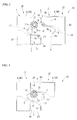
FIG. 1 is an exploded perspective view of a sheath removing unit according to a first embodiment of the invention. -
FIG. 2 is a front view of the sheath removing unit according to the first embodiment. -
FIG. 3 is a front view illustrating the operation of the sheath removing unit according to the first embodiment. -
FIG. 4 is a front view illustrating the operation of the sheath removing unit according to the first embodiment. -
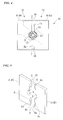
FIG. 5 is a perspective view of a modification of blade bodies of the first embodiment. -
FIG. 6 is a perspective view of a modification of an optical fiber guide of the first embodiment. -
FIG. 7 is a front view of a sheath removing unit according to a second embodiment of the invention. -
FIG. 8 is a front view illustrating the operation of the sheath removing unit according to the second embodiment. -
FIG. 9 is a perspective view schematically showing an optical fiber-sheath removing device of the invention. -
FIG. 10 is an exploded perspective view of an example of a sheath removing unit in the related art. -
FIG. 11 is a cross-sectional view of the sheath removing unit in the related art. -
FIG. 12 is a front view of a blade receiving plate that is used in the sheath removing unit in the related art. -
-
FIG. 1 is an exploded perspective view of a sheath removing unit 10 (10A) according to a first embodiment of the invention. -
FIG. 2 is a front view of thesheath removing unit 10A according to the first embodiment. -
FIG. 3 is a front view illustrating the operation of thesheath removing unit 10A according to the first embodiment. -
FIG. 4 is a front view illustrating the operation of thesheath removing unit 10A according to the first embodiment. - The
sheath removing unit 10A according to this embodiment removes asheath 21b of a sheathedoptical fiber 21 from a bareoptical fiber 21a. - As shown in
FIGS. 1 and2 , thesheath removing unit 10A according to this embodiment includes asheath removing blade 1, anoptical fiber guide 2, and apositioning plate 3. - The
sheath removing blade 1, theoptical fiber guide 2, and thepositioning plate 3 are disposed in this order in a thickness direction thereof. - The
sheath removing blade 1, theoptical fiber guide 2, and thepositioning plate 3 may be disposed so as to be separated from each other and may be disposed so as to be laminated on each other. - The sheathed
optical fiber 21 is, for example, an optical fiber core or an optical fiber strand. - The
sheath removing blade 1 includes a pair of substantiallyrectangular blade bodies - In the following description, one
blade body 4 is denoted byreference numeral 4A and theother blade body 4 is denoted byreference numeral 4B. - These blade bodies 4 (4A and 4B) are disposed in substantially the same plane so that opposite surfaces (opposite edge portions) 4a and 4a face each other.
- A
concave blade portion 5 having a semicircular shape is formed substantially in the middle of each of theopposite edge portions - The portions of the
opposite edge portions concave blade portions 5, formstraight portions 6 that are formed in a linear shape. - When the respective blade bodies 4 (4A and 4B) come into contact with each other so that these
opposite edge portions concave blade portions straight portions - The
concave blade portions sheath 21b of the sheathedoptical fiber 21 and is larger than the outer diameter of the bareoptical fiber 21a. - Accordingly, the
concave blade portions sheath 21b without damaging the bareoptical fiber 21a. -
Positioning mechanisms straight portions 6 of the blade bodies 4 (4A and 4B) as shown inFIG. 5 . - When these
blade bodies sheath 21b of the sheathedoptical fiber 21, thepositioning mechanisms blade bodies sheath removing unit 10A) in a height direction. - For example, as shown in
FIG. 5 , projectingportions 4b that are formed at oneblade body 4A and recessedportions 4c that are formed at theother blade body 4B so as to be fitted to the projecting portions 48 are used as the positioning mechanisms. - When the
sheath 21b is removed, the projectingportions 4b and the recessedportions 4c are fitted to each other, so that the blade bodies 4 (4A and 4B) are positioned in the height direction. - Accordingly, a problem that the
sheath 21b partially remains without being completely removed or breakage occurs at the bareoptical fiber 21a due to the deviation of the positions of the blade bodies 4 (4A and 4B) is suppressed at the time of the removal of thesheath 21b. - Thus, a bare
optical fiber 21a from which asheath 21b has been removed is more stably provided. -
FIG. 5 has shown a case where the proj ectingportions 4b are formed at oneblade body 4A and the recessedportions 4c are formed at theother blade body 4B. However, for example, the projectingportion 4b may be formed at the upper portion of oneblade body 4A and the recessedportion 4c may be formed at the lower portion of theblade body 4A. - Furthermore, the number of the projecting
portions 4b and the recessedportions 4c is not particularly limited. - The sheathed
optical fiber 21, which is used in the invention, is not particularly limited. - For example, the sheathed optical fiber is a single mode fiber (based on ITU-T G652 B), and Fujikura FutureGuide(R)-SM and the like may be used as the sheathed optical fiber.
- The
optical fiber guide 2 includes a pair ofguide bodies 7 and 8 (afirst guide body 7 and a second guide body 8) formed in the shape of a thin plate. - The pair of
guide bodies sheath removing blade 1 in the longitudinal direction of the sheathedoptical fiber 21. - In this case, the
sheath removing blade 1 is disposed parallel to the pair ofguide bodies - The
first guide body 7 and thesecond guide body 8 are disposed in the same plane so as to face each other.
in this specification, the opposite surfaces of thefirst guide body 7 and thesecond guide body 8 facing each other are referred to asopposite edge portions - The
opposite edge portion 8a of the second guide body has a shape corresponding to the shape of theopposite edge portion 7a of thefirst guide body 7. - As shown in
FIG. 1 , upper andlower edge portions first guide body 7 are formed parallel to each other. - The
opposite edge portion 7a of thefirst guide body 7 includes an upperinclined portion 11 that descends from theupper edge portion 7b at a predetermined angle from oneend 7d of thefirst guide body 7 toward theother end 7e thereof, amiddle portion 12 that extends from the lower end of the upperinclined portion 11 so as to be parallel to theupper edge portion 7b, and a lowerinclined portion 13 that descends from themiddle portion 12 at a predetermined angle. - As shown in
FIG. 2 , an inclination angle θ1 of the lowerinclined portion 13 with respect to thelower edge portion 7c is preferably in the range of 15 to 45° and more preferably in the range of 20 to 35°. - If the inclination angle θ1 is smaller than 15°, a range R where the sheathed
optical fiber 21 can be led to an appropriate position (into the concave blade portions 5) becomes narrow. - On the other hand, if the inclination angle θ1 is larger than 45°, it is difficult to smoothly move the sheathed
optical fiber 21 to an appropriate position. - It is preferable that the lower
inclined portion 13 of thefirst guide body 7 be formed at a position corresponding to the lowerstraight portion 6 of thesheath removing blade 1 as shown inFIG. 2 . - It is preferable that the position of the
middle portion 12 of thefirst guide body 7 be a position corresponding to the vicinity of the lower end of theconcave blade portion 5 of oneblade body 4A. - That is, it is preferable that the position of the
middle portion 12 of thefirst guide body 7 be a position corresponding to the lower end of theconcave blade portion 5 or a position slightly below this position. - Due to this structure, the sheathed
optical fiber 21 is guided by the lowerinclined portion 13 of thefirst guide body 7 so as to be introduced to theconcave blade portion 5 of thesheath removing blade 1. - As shown in
FIGS. 1 and2 , a portion of thefirst guide body 7, which includes themiddle portion 12 and the lowerinclined portion 13, forms a first protrudingportion 34 that protrudes from the lower portion of a main body portion 33 (a portion including the upper inclined portion 11) to the right side inFIG. 2 . - That is, the first protruding
portion 34 protrudes along themiddle portion 12 toward theother blade body 4B. - For this reason, the lower
inclined portion 13 is inclined so as to gradually descend toward the protruding direction of the first protruding portion 34 (that is, toward the outside). - As shown in
FIG. 1 , upper andlower edge portions second guide body 8 are formed parallel to each other. - The
opposite edge portion 8a of thesecond guide body 8 includes an upperinclined portion 14 that descends at a predetermined angle from oneend 8d toward theother end 8e, amiddle portion 15 that extends from the lower end of the upperinclined portion 14 so as to be parallel to theupper edge portion 8b, and a lowerinclined portion 16 that descends from themiddle portion 15 at a predetermined angle. - As described above, the
opposite edge portion 8a of thesecond guide body 8 has a shape corresponding to the shape of theopposite edge portion 7a of thefirst guide body 7. - That is, the upper
inclined portion 14 of thesecond guide body 8 is formed substantially parallel to the upperinclined portion 11 of thefirst guide body 7. - The
middle portion 15 of thesecond guide body 8 is formed substantially parallel to themiddle portion 12 of thefirst guide body 7. - The lower
inclined portion 16 of thesecond guide body 8 is formed substantially parallel to the lowerinclined portion 13 of thefirst guide body 7. - Accordingly, the upper
inclined portion 14, themiddle portion 15, and the lowerinclined portion 16 of thesecond guide body 8 are formed so as to face the upperinclined portion 11, themiddle portion 12, and the lowerinclined portion 13 of thefirst guide body 7, respectively, when theopposite edge portion 7a of thefirst guide body 7 and theopposite edge portion 8a of thesecond guide body 8 face each other. - As shown in
FIG. 2 , an inclination angle θ2 of the upperinclined portion 14 of thesecond guide body 8 with respect to theupper edge portion 8b is preferably in the range of 15 to 45° and more preferably in the range of 20 to 35°, for the same reason as the inclination angle θ1 of the lowerinclined portion 13 of thefirst guide body 7. - It is preferable that the upper
inclined portion 14 of thesecond guide body 8 be formed at a position corresponding to the upperstraight portion 6 of thesheath removing blade 1 as shown inFIG. 2 . - It is preferable that the position of the
middle portion 15 of thesecond guide body 8 be a position corresponding to the vicinity of the upper end of theconcave blade portion 5 of theother blade body 4B. - That is, it is preferable that the position of the
middle portion 15 of thesecond guide body 8 be a position corresponding to the upper end of theconcave blade portion 5 or a position slightly above this position. - Due to this structure, the sheathed
optical fiber 21 is guided by the upperinclined portion 14 of thesecond guide body 8 so as to be introduced to theconcave blade portion 5 of thesheath removing blade 1. - It is preferable that the difference between the height of the
middle portion 12 of thefirst guide body 7 and the height of themiddle portion 15 of thesecond guide body 8 be substantially equal to the outer diameter of the sheathedoptical fiber 21 or be slightly larger than the outer diameter of the sheathedoptical fiber 21. - Accordingly, it is possible to lead the sheathed
optical fiber 21 to theconcave blade portion 5 while the vertical movement of the sheathedoptical fiber 21 is regulated between themiddle portions - As shown in
FIGS. 1 and2 , a portion of thesecond guide body 8, which includes themiddle portion 15 and the upperinclined portion 14, forms a second protrudingportion 36 that protrudes from the upper portion of a main body portion 35 (a portion including the lower inclined portion 16) to the left side inFIG. 2 . - That is, the second protruding
portion 36 protrudes along themiddle portion 15 toward oneblade body 4A. - For this reason, the upper
inclined portion 14 is inclined so as to gradually ascend toward the protruding direction of the second protruding portion 36 (that is, toward the outside). - The
positioning plate 3 leads the sheathedoptical fiber 21 into a space between thefirst guide body 7 and thesecond guide body 8 of theoptical fiber guide 2, particularly, the range R shown inFIG. 2 , and positions the sheathedoptical fiber 21. - This
positioning plate 3 includes a pair of positioning portions 18 (onepositioning portion 18A and theother positioning portion 18B) as shown inFIG. 1 , and these positioning portions are disposed so as to face each other. - In this specification, the opposite surfaces of these positioning portions 18 (18A and 18B) facing each other are referred to as
opposite edge portions 18a. - These positioning portions 18 (18A and 18B) are provided parallel to the
optical fiber guide 2 in the longitudinal direction of the sheathedoptical fiber 21. - Concave receiving
portions optical fiber 21, are formed substantially in the middle of theopposite edge portions - When the positioning portions 18 (18A and 18B) come into contact with each other so as to face each other, the
concave receiving portions - The
concave receiving portions optical fiber 21. - That is, the
concave receiving portions optical fiber 21 is received without inconvenience. - When the
sheath removing blade 1, theoptical fiber guide 2, and thepositioning plate 3 are disposed so as to be superimposed, theconcave receiving portions concave blade portions 5 of thesheath removing blade 1. -
Positioning mechanisms opposite edge portions FIG. 6 . - When the
sheath 21b is removed, thepositioning mechanisms sheath removing unit 10A) in the thickness direction of the positioning plate. - For example, as shown in
FIG. 6 , recessedportions 18b that are formed at onepositioning portion 18A and protrudingportions 18c that are formed at theother positioning portion 18B so as to be fitted to the recessedportions 18b are used as the positioning mechanisms. - When the
opposite edge portions 18a of onepositioning portion 18A and theother positioning portion 18B come into contact with each other at the time of the removal of thesheath 21b, the recessedportion 18b and the protrudingportion 18c are fitted to each other and thepositioning plate 3 is positioned in the thickness direction thereof. - Accordingly, the
concave blade portion 5 of oneblade body 4A and theconcave blade portion 5 of theother blade body 4B come into contact with thesheath 21b of the sheathedoptical fiber 21 without deviating from each other in the thickness direction of the blade body, so that thesheath 21b is uniformly removed. - Even though the
sheath removing unit 10A according to this embodiment has a basic structure that includes thesheath removing blade 1 and the optical fiber guide 2 (that is, a structure that does not include the positioning plate 3), it is possible to guide the sheathedoptical fiber 21, which has a tendency to bend, to theconcave blade portions 5 that are formed at the center of thesheath removing blade 1 and to remove thesheath 21b. - It is possible to more reliably guide the sheathed
optical fiber 21 to theconcave blade portions 5 that are formed at the center of thesheath removing blade 1 by adding thepositioning plate 3 to this structure. - As a result, it is possible to prevent the sheathed
optical fiber 21 from being damaged at the time of the removal of thesheath 21b and to secure the strength of the optical fiber from which the sheath has been removed. - One
blade body 4A, thefirst guide body 7, and onepositioning portion 18A of thesheath removing unit 10A according to this embodiment integrally operate as afirst unit body 31. - Additionally, the
other blade body 4B, thesecond guide body 8, and theother positioning portion 18B integrally operate as asecond unit body 32. - One or both of the
first unit body 31 and thesecond unit body 32 can be moved by, for example, a moving mechanism (not shown) so as to approach each other or so as to be separated from each other. - When seen in plan view, the first protruding
portion 34 of thefirst guide body 7 of thefirst unit body 31 protrudes from theopposite edge portion 4a of oneblade body 4A toward thesecond unit body 32 as shown inFIG. 2 . - When seen in plan view, the second protruding
portion 36 of thesecond guide body 8 of thesecond unit body 32 protrudes from theopposite edge portion 4a of theother blade body 4B toward thefirst unit body 31. - Next, the use of the
sheath removing unit 10A according to this embodiment will be described. - As shown in
FIG. 2 , thefirst unit body 31 and thesecond unit body 32 are made to be separated from each other and a sheathedoptical fiber 21 is disposed between the first unit body and the second unit body. - In the example shown in
FIG. 2 , the height of the sheathedoptical fiber 21 corresponds to a position corresponding to the upperinclined portion 14 of thesecond guide body 8. - When the
first unit body 31 and thesecond unit body 32 are made to approach each other as shown inFIG. 3 , the sheathedoptical fiber 21 comes into contact with the upperinclined portion 14 of thesecond guide body 8. - When these
first unit body 31 andsecond unit body 32 are made to further approach each other, the sheathedoptical fiber 21 is pressed by the upperinclined portion 14 of thesecond unit body 32 and is moved downward along thestraight portion 6 of theblade body 4 of thefirst unit body 31. - When seen in plan view in the state shown in
FIG. 3 , the sheathedoptical fiber 21 is positioned in aspace 37 that is surrounded by the first protrudingportion 34, oneblade body 4A, theother blade body 4B, and the second protrudingportion 36. - Both the
first unit body 31 and thesecond unit body 32 may be moved so as to approach each other, and one of the first unit body and the second unit body may be moved so as to approach the other thereof. - In the example shown in
FIG. 3 , the moving direction of the first or second unit body is substantially the same as the protruding direction of the first protrudingportion 34 or the second protrudingportion 36. - When the
first unit body 31 and thesecond unit body 32 are made to further approach each other as shown inFIG. 4 , the sheathedoptical fiber 21 is pressed by the upperinclined portion 14 of thesecond unit body 32 and is further moved downward. - In this case, the vertical movement of the sheathed
optical fiber 21 is regulated between themiddle portion 12 of the first unit body 31 (first guide body 7) and themiddle portion 15 of the second unit body 32 (second guide body 8). - When the
first unit body 31 and thesecond unit body 32 are made to further approach each other in this state so that theopposite edge portions blade bodies optical fiber 21 is caught by theconcave blade portion 5 of the oneblade body 4A and theconcave blade portion 5 of theother blade body 4B. - Additionally, as shown in
FIG. 1 , the sheathedoptical fiber 21 is led into theconcave receiving portions positioning plate 3 by the movement of thefirst unit body 31 and thesecond unit body 32 and is positioned in the concave receiving portions. - In this state, the sheathed
optical fiber 21 is moved relative to thesheath removing unit 10 in the thickness direction of thesheath removing blade 1, that is, in the direction perpendicular to the plane ofFIGS. 2 to 4 . - Due to this operation, a force is applied to the
sheath 21b in the longitudinal direction of the sheathedoptical fiber 21 by theconcave blade portions sheath 21b is removed from the bareoptical fiber 21a. - If the sheathed
optical fiber 21 is disposed at a low position in thespace 37, for example, at the height corresponding to the lowerinclined portion 13 of thefirst guide body 7, the sheathedoptical fiber 21 is moved upward by the lowerinclined portion 13 and led into theconcave blade portion 5. - As described above, in the
sheath removing unit 10A according to this embodiment, the sheathedoptical fiber 21 is led into theconcave blade portion 5 and theconcave receiving portion 19 by the upperinclined portion 14 of thesecond guide body 8 or the lowerinclined portion 13 of thefirst guide body 7 in thespace 37 that is surrounded by the first protrudingportion 34, the oneblade body 4A, theother blade body 4B, and the second protrudingportion 36 shown inFIG. 3 . - Accordingly, even if a sheathed
optical fiber 21 has a tendency to bend, the sheathedoptical fiber 21 is led into theconcave blade portion 5 and theconcave receiving portion 19 by thefirst guide body 7 or thesecond guide body 8. As a result, thesheath 21b of the sheathed optical fiber is removed at an exact position. - In addition, the
sheath removing unit 10A according to this embodiment is easily applied to optical fiber-sheath removing devices having different specifications. - That is, if the
sheath removing unit 10A according to this embodiment is mounted instead of a sheath removing blade that is used in an existing optical fiber-sheath removing device, the above-mentioned advantage is obtained. -
FIG. 7 is a front view of a sheath removing unit 10 (10B) according to a second embodiment of the invention. - The same components as the components of the
sheath removing unit 10A according to the first embodiment are denoted by the same reference numerals in the following description and the description thereof will be omitted. - A
sheath removing unit 10B according to this embodiment is different from thesheath removing unit 10A according to the first embodiment in that aliquid inlet 41 is formed at onepositioning plate 18A and agas inlet 43 is formed at theother positioning plate 18B. - Additionally, the sheath removing unit according to this embodiment is different from the sheath removing unit according to the first embodiment in that an
upper edge portion 7b of afirst guide body 7 is formed at the position corresponding to the vicinity of the upper end of onepositioning portion 18A and alower edge portion 8c of asecond guide body 8 is formed at the position corresponding to the vicinity of the lower end of theother positioning portion 18B. - Both the
liquid inlet 41 and thegas inlet 43 have been formed in this embodiment, but only one of the liquid inlet and the gas inlet may be formed at the positioning portions 18 (18A and 18B). - A
sheath removing blade 1 is not shown inFIGS. 7 and8 , but the structure of thesheath removing blade 1 is the same as that of the sheath removing blade of the first embodiment. - The
gas inlet 43 is formed at theother positioning plate 18B so as to be opened to aspace 42 between thefirst guide body 7 and thesecond guide body 8 as shown inFIG. 8 when thefirst unit body 31 and thesecond unit body 32 are combined with each other. - Gas such as air is introduced to the
space 42 from thegas inlet 43. -
FIG. 8 is a view showing a state where the sheathedoptical fiber 21 is positioned. - In this state, a
sheath 21b is removed by the sheath removing blade 1 (not shown inFIGS. 7 and8 ). - Accordingly, a scrap, which is the removed
sheath 21b, is generated in thespace 42 between thefirst guide body 7 and thesecond guide body 8. - Here, when the gas is introduced to the
space 42 from thegas inlet 43, the flow of gas is generated from thegas inlet 43 to the outside of thespace 42. - As a result, the scrap is discharged from the
space 42 together with the flow of gas. - While the
sheath 21b is removed, gas may be frequently introduced.
Alternatively, after a predetermined amount of thesheath 21b is removed, gas may be introduced. - The
liquid inlet 41 is formed at onepositioning plate 18A so as to be opened to thespace 42 as shown inFIG. 8 . - Liquid is introduced to the
space 42 from theliquid inlet 41. - For example, alcohol such as ethanol, water, or the like is used as this liquid.
- When the liquid is introduced to the
space 42 from theliquid inlet 41, the flow of liquid is generated from theliquid inlet 43 to the outside of thespace 42. - As a result, the scrap is discharged from the
space 42 together with the flow of liquid. - If not only gas but also liquid is introduced to the
space 42, it is possible to more effectively discharge the scrap from thespace 42. - Liquid, which is introduced to the
space 42, is also supplied to theconcave blade portions 5. - For this reason, when alcohol is used as this liquid, the
sheath 21b is removed by theconcave blade portions 5 while friction between theconcave blade portion 5 and thesheath 21b is reduced by alcohol. - At this time, the
concave blade portions 5 are also cleaned at the same time using alcohol. - Accordingly, the
sheath 21b is more effectively removed and nicks in theconcave blade portion 5 caused by friction or the scrap are suppressed, so that theconcave blade portion 5 can be used for a long time. - It is preferable that
liquid inlet 41 be formed at a position above the concave blade portion 5 (concave receiving portion 19). - Accordingly, the liquid, which has been introduced to the
space 42, is more actively supplied to a portion, which removes thesheath 21b, by the gravity applied to the liquid. - For this reason, as compared to the case where the
liquid inlet 41 is formed at a position below theconcave receiving portions 19, it is possible to stably supply liquid to a portion that removes thesheath 21b and to more effectively perform the removal of the scrap from thespace 42, the cleaning of theconcave blade portions 5, and the reduction of the friction between thesheath 21b and theconcave blade portions 5. - Liquid may be introduced after a predetermined amount of the
sheath 21b is removed. However, considering the above-mentioned action of liquid to theconcave blade portions 5, it is preferable that liquid be frequently introduced while thesheath 21b is removed. - As described above, in the
sheath removing unit 10B according to this embodiment, the scrap is discharged from thespace 42 by the gas that is introduced to thespace 42 from thegas inlet 43 or the liquid that is introduced to thespace 42 from theliquid inlet 41. - Accordingly, it is possible to suppress the breakage of the bare optical fiber that is caused by the interference between the
sheath removing blade 1 and residues of the scrap during the removal of the sheath, and to reduce the amount of the scrap on the bare optical fiber from which the sheath has been removed. - In the
sheath removing unit 10B according to this embodiment, theupper edge portion 7b of thefirst guide body 7 is formed at the position corresponding to the upper end portion of onepositioning portion 18A (and oneblade body 4A). - Additionally, the
lower edge portion 8c of thesecond guide body 8 is formed at the position corresponding to the lower end portion of theother positioning portion 18B (and theother blade body 4B). - Accordingly, the flow passage of liquid or gas, which has been introduced to the
space 42, is formed to the outside of thespace 42. - That is, in the
sheath removing unit 10B according to this embodiment, thefirst guide body 7 and thesecond guide body 8 form not only the guide of the sheathedoptical fiber 21 but also the flow passage of gas and liquid that are introduced to thespace 42. - As a result, gas or liquid, which is introduced to the
space 42, is efficiently introduced to a portion, which efficiently removes thesheath 21b, without being unnecessarily dispersed. - In addition, since the above-mentioned advantage is obtained without the increase of the number of parts, the reduction of the size of a device including the
sheath removing unit 10B according to this embodiment is facilitated. - Even in this embodiment, like in the first embodiment,
positioning mechanisms positioning mechanisms - The same advantage as the advantage of the first embodiment is obtained.
-
FIG. 9 is a view schematically showing an optical fiber-sheath removing device 50 according to an embodiment of the invention. - The optical fiber-
sheath removing device 50 is an automatic device that includes the above-mentioned sheath removing unit 10 (10A or 10B), a drive mechanism (not shown), and ahousing 51. The drive mechanism (not shown) drives thefirst unit body 31 and thesecond unit body 32 of thesheath removing unit 10 or one of the first unit body and the second unit body. Thehousing 51 receives the sheath removing unit and the drive mechanism therein. - A moving mechanism is adapted to make, for example, the blade bodies 4 (4A and 4B) of the
sheath removing blade 1, thefirst guide body 7 and thesecond guide body 8 of theoptical fiber guide 2, and the positioning portions 18 (18A and 18B) of thepositioning plate 3 operate so as to be automatically opened and closed (operate so as to be moved in a horizontal direction), or is adapted to make thefirst unit 31 and the second unit operate so as to be automatically moved in a horizontal direction. - In the optical fiber-
sheath removing device 50 according to this embodiment, when the sheathedoptical fiber 21 is introduced into the optical fiber-sheath removing device 50, thefirst unit body 31 and thesecond unit body 32 are moved so as to approach each other by the drive mechanism or one of the first unit body and the second unit body is moved so as to approach the other by the drive mechanism. Accordingly, the sheathedoptical fiber 21 is guided to and held at an appropriate position. - When the
first unit body 31 and thesecond unit body 32 are moved so as to approach each other or one of the first unit body and the second unit body is moved so as to approach the other thereof, thesheath 21b of the sheathedoptical fiber 21 is cut and removed by thesheath removing blade 1. - In this case, liquid is introduced to the
space 42 from theliquid inlet 41 and gas is introduced to thespace 42 from thegas inlet 43 in the optical fiber-sheath removing device 50 on which thesheath removing unit 10B according to the second embodiment is mounted. - Accordingly, it is possible to discharge the scrap, which is generated during an operation for removing the sheath, from a portion that removes the
sheath 21b. - Therefore, it is possible to suppress the breakage of the bare optical fiber that is caused by the interference between the
sheath removing blade 1 and residues of the scrap during the removal of the sheath, and to reduce the amount of the scrap on the bare optical fiber from which the sheath has been removed. - Additionally, since the optical fiber-
sheath removing device 50 may be an automatic device, it is possible to provide a stable bare optical fiber without the accuracy deviation in removing the sheath that is caused by the skill of a worker. - Furthermore, since breakage does not easily occur at the obtained bare optical fiber, the deterioration of the breaking strength of the obtained bare optical fiber is suppressed.
- For this reason, it is possible to provide a bare optical fiber that is suitable for a long-term use.
- According to the sheath removing unit of the invention, even though a sheathed optical fiber has a tendency to bend, it is possible to reliably lead the sheathed optical fiber into the concave blade portions of the sheath removing blade.
- Accordingly, it is possible to remove a sheath while the optical fiber is held at an exact position, and to suppress the deterioration or the like of the breaking strength of the optical fiber that is caused by the breakage occurring at a bare optical fiber when the sheath is removed.
- Furthermore, according to the optical fiber-sheath removing device of the invention, it is possible to provide a stable bare optical fiber without the deviation of accuracy in removing the sheath that is caused by the skill of a worker.
- In addition, since breakage does not easily occur at the obtained bare optical fiber, the deterioration of the breaking strength of the obtained bare optical fiber is suppressed.
- For this reason, it is possible to provide a bare optical fiber that is suitable for long time use.
-
- 1:
- sheath removing blade
- 2:
- optical fiber guide
- 3:
- positioning plate
- 4 (4A, 4B):
- blade body
- 4a:
- opposite edge portion
- 4b:
- projecting portion
- 4c:
- recessed portions
- 5:
- concave blade portion
- 7:
- first guide body
- 7a:
- opposite edge portion (inner edge)
- 8:
- second guide body
- 8a:
- opposite edge portion (inner edge)
- 10 (10A, 10B):
- sheath removing unit
- 12:
- middle portion of first guide body
- 13:
- lower inclined portion of first guide body
- 14:
- upper inclined portion of second guide body
- 15:
- middle portion of second guide body
- 18:
- positioning portion
- 18a:
- opposite edge portion of positioning portion
- 18b:
- recessed portion
- 18c:
- protruding portion
- 19:
- concave receiving portion
- 21:
- sheathed optical fiber
- 21a:
- bare optical fiber
- 21b:
- sheath
- 37:
- space surrounded by first protruding portion, a pair of blade bodies, and second protruding portion
- 42:
- space between a first guide body and a second guide body
- 41:
- liquid inlet
- 43:
- gas inlet
Claims (9)
- A sheath removing unit that removes a sheath of a sheathed optical fiber comprising:a sheath removing blade including a pair of blade bodies which is disposed so as to face each other and concave blade portions which is formed on each opposite surfaces of the blade bodies; andan optical fiber guide disposed so as to be superimposed on the sheath removing blade, whereinthe optical fiber guide includes a first guide body and a second guide body that are disposed so as to face each other,the first guide body includes a first protruding portion which is disposed so as to be superimposed on one blade body of the blade bodies and protrudes from the opposite surface of one blade body toward the other blade body when seen in plan view,the second guide body includes a second protruding portion that is disposed so as to be superimposed on the other blade body and protrudes from the opposite surface of the other blade body toward one blade body when seen in plan view,a lower inclined portion, which is outwardly inclined toward a protruding direction of the first protruding portion, is formed on a surface of the first protruding portion facing the second guide body, andan upper inclined portion, which is outwardly inclined toward a protruding direction of the second protruding portion, is formed on a surface of the second protruding portion facing the first guide body.
- The sheath removing unit according to claim 1, wherein
an inclination angle (θ1) of the lower inclined portion with respect to the protruding direction of the first protruding portion and an inclination angle (θ2) of the upper inclined portion with respect to the protruding direction of the second protruding portion are in the range of 15 to 45°. - The sheath removing unit according to claim 1, further comprising:a positioning plate that positions the sheathed optical fiber and that is disposed on the side opposite to the side of the optical fiber guide where the sheath removing blade is positioned, whereinthe positioning plate includes a pair of positioning portions disposed so as to face each other,one positioning portion of the positioning portions is disposed so as to operate integrally with the first guide body,the other positioning portion is disposed so as to operate integrally with the second guide body, andreceiving portions, which receive the sheathed optical fiber in a radial direction of the sheathed optical fiber, are formed on opposite surfaces of the one positioning portion and the other positioning portion at positions corresponding to the concave blade portions of the sheath removing blade, respectively.
- The sheath removing unit according to claim 3, wherein
a gas inlet, which is opened to a space between the first guide body and the second guide body, is formed at the positioning plate. - The sheath removing unit according to claim 3, wherein
a liquid inlet, which is opened to a space between the first guide body and the second guide body, is formed at the positioning plate. - The sheath removing unit according to claim 3, wherein
a liquid inlet, which is opened to a space between the first guide body and the second guide body, is formed at the one positioning plate, and
a gas inlet, which is opened to the space, is formed at the other positioning plate. - The sheath removing unit according to claim 1, wherein
positioning mechanisms are provided at the pair of blade bodies, respectively. - The sheath removing unit according to claim 3, wherein
positioning mechanisms are provided at the pair of positioning plates, respectively. - An optical fiber-sheath removing device that includes the sheath removing unit according to claim 1.
Applications Claiming Priority (2)
| Application Number | Priority Date | Filing Date | Title |
|---|---|---|---|
| JP2009049819 | 2009-03-03 | ||
| PCT/JP2010/001449 WO2010100912A1 (en) | 2009-03-03 | 2010-03-03 | Coating removal unit and optical fiber coating removal apparatus |
Publications (3)
| Publication Number | Publication Date |
|---|---|
| EP2405289A1 true EP2405289A1 (en) | 2012-01-11 |
| EP2405289A4 EP2405289A4 (en) | 2015-10-28 |
| EP2405289B1 EP2405289B1 (en) | 2019-05-15 |
Family
ID=42709478
Family Applications (1)
| Application Number | Title | Priority Date | Filing Date |
|---|---|---|---|
| EP10748511.2A Active EP2405289B1 (en) | 2009-03-03 | 2010-03-03 | Coating removal unit and optical fiber coating removal apparatus |
Country Status (6)
| Country | Link |
|---|---|
| US (1) | US8522648B2 (en) |
| EP (1) | EP2405289B1 (en) |
| JP (1) | JP5216911B2 (en) |
| KR (1) | KR101264135B1 (en) |
| CN (1) | CN102334051B (en) |
| WO (1) | WO2010100912A1 (en) |
Cited By (1)
| Publication number | Priority date | Publication date | Assignee | Title |
|---|---|---|---|---|
| US10514505B2 (en) | 2017-02-20 | 2019-12-24 | Fujikura Ltd. | Coating removal blade, removal blade unit and optical fiber coating removal apparatus |
Families Citing this family (9)
| Publication number | Priority date | Publication date | Assignee | Title |
|---|---|---|---|---|
| CN103904590A (en) * | 2012-12-26 | 2014-07-02 | 鸿富锦精密工业(深圳)有限公司 | Wire-stripping device |
| RU2665312C1 (en) * | 2014-10-02 | 2018-08-29 | Корнинг Рисерч энд Дивелопмент Корпорейшн | One-use tool for removing protective sleeve from optical fiber |
| JP6431740B2 (en) * | 2014-10-14 | 2018-11-28 | 株式会社フジクラ | Optical fiber coating removal tool and optical fiber coating removal method |
| EP3089294B1 (en) * | 2015-04-30 | 2019-07-31 | Komax Holding AG | Cable processing device and method for removing a screen film from a shielded, multi-core round cable |
| JP6474851B2 (en) * | 2017-04-14 | 2019-02-27 | 株式会社フジクラ | Coating removal tool and coating removal method |
| WO2019202663A1 (en) * | 2018-04-17 | 2019-10-24 | 株式会社フジクラ | Coating removal tool and coating removal method |
| US11493722B2 (en) * | 2020-10-16 | 2022-11-08 | Metra Electronics Corporation | Cable stripping tool |
| CN118567031A (en) | 2023-02-28 | 2024-08-30 | 株式会社藤仓 | Coating removal device and blade manufacturing method |
| CN116594113B (en) * | 2023-07-18 | 2023-09-19 | 国网吉林省电力有限公司信息通信公司 | Optical cable insulation layer stripping device for optical cable installation engineering |
Family Cites Families (18)
| Publication number | Priority date | Publication date | Assignee | Title |
|---|---|---|---|---|
| JPS4610997Y1 (en) * | 1967-07-31 | 1971-04-16 | ||
| US4117749A (en) * | 1976-08-09 | 1978-10-03 | The United States Of America As Represented By The Administrator Of The National Aeronautics And Space Administration | Wire stripper |
| JPH0529443Y2 (en) * | 1985-01-25 | 1993-07-28 | ||
| JPS6141207U (en) * | 1985-04-18 | 1986-03-15 | 日本電信電話株式会社 | optical fiber cutting equipment |
| JPH0224806U (en) * | 1988-08-03 | 1990-02-19 | ||
| JPH07118855B2 (en) * | 1991-05-22 | 1995-12-18 | ヒロセ電機株式会社 | Cable coating stripping device |
| JPH0529443A (en) * | 1991-07-25 | 1993-02-05 | Fujitsu Ltd | Wafer cooling device and cooling method |
| JPH0757058B2 (en) * | 1992-03-10 | 1995-06-14 | 日本オートマチックマシン株式会社 | Double coated wire strip forming equipment |
| JPH06276637A (en) * | 1993-03-19 | 1994-09-30 | Toyo Tanshi Kk | Wire stripper |
| JPH09113732A (en) | 1995-10-18 | 1997-05-02 | Fujikura Ltd | Optical fiber coating removal tool |
| JP2001311831A (en) * | 2000-04-28 | 2001-11-09 | Fujikura Ltd | Optical fiber coating remover |
| JP3288676B2 (en) | 2000-05-10 | 2002-06-04 | 日本オートマチックマシン株式会社 | Coaxial cable terminal processing method and apparatus |
| JP2002004998A (en) | 2000-06-20 | 2002-01-09 | Komatsu Ltd | Oblique axis fixed displacement hydraulic motor |
| CA2384467A1 (en) | 2000-07-10 | 2002-01-17 | Sumitomo Electric Industries, Ltd. | Optical fiber wire holder, fused connection device, cutting device, and method of connecting optical fiber |
| JP4535219B2 (en) | 2001-06-12 | 2010-09-01 | 住友電気工業株式会社 | Optical fiber coating removal device |
| JP2004077909A (en) | 2002-08-20 | 2004-03-11 | Furukawa Electric Co Ltd:The | Optical fiber coating removal processing method and coating removal device |
| JP2009049819A (en) | 2007-08-21 | 2009-03-05 | Aruze Corp | IP phone system |
| KR100971071B1 (en) * | 2009-10-26 | 2010-07-20 | 지성훈 | Wire stripper |
-
2010
- 2010-03-03 KR KR1020117019638A patent/KR101264135B1/en active Active
- 2010-03-03 CN CN2010800091087A patent/CN102334051B/en active Active
- 2010-03-03 WO PCT/JP2010/001449 patent/WO2010100912A1/en not_active Ceased
- 2010-03-03 JP JP2011502648A patent/JP5216911B2/en active Active
- 2010-03-03 EP EP10748511.2A patent/EP2405289B1/en active Active
-
2011
- 2011-08-31 US US13/222,767 patent/US8522648B2/en active Active
Non-Patent Citations (1)
| Title |
|---|
| See references of WO2010100912A1 * |
Cited By (1)
| Publication number | Priority date | Publication date | Assignee | Title |
|---|---|---|---|---|
| US10514505B2 (en) | 2017-02-20 | 2019-12-24 | Fujikura Ltd. | Coating removal blade, removal blade unit and optical fiber coating removal apparatus |
Also Published As
| Publication number | Publication date |
|---|---|
| EP2405289B1 (en) | 2019-05-15 |
| US20110308358A1 (en) | 2011-12-22 |
| KR20110107398A (en) | 2011-09-30 |
| CN102334051B (en) | 2013-07-24 |
| KR101264135B1 (en) | 2013-05-14 |
| CN102334051A (en) | 2012-01-25 |
| JP5216911B2 (en) | 2013-06-19 |
| US8522648B2 (en) | 2013-09-03 |
| WO2010100912A1 (en) | 2010-09-10 |
| JPWO2010100912A1 (en) | 2012-09-06 |
| EP2405289A4 (en) | 2015-10-28 |
Similar Documents
| Publication | Publication Date | Title |
|---|---|---|
| EP2405289B1 (en) | Coating removal unit and optical fiber coating removal apparatus | |
| CN102667558B (en) | Optical fiber holder and method for holding optical fiber core | |
| EP2693244B1 (en) | Optical fiber coating removing device and method of removing coating | |
| TWI464473B (en) | Optical fiber clamping mechanism and optical fiber connector using the same | |
| JP6664426B2 (en) | Optical fiber cutting method and optical fiber cutter | |
| TWI475272B (en) | The optical fiber connector | |
| US8826517B2 (en) | Fiber handler having multiple sides | |
| CN107085267B (en) | Optical fiber holder and optical fiber cutting device capable of mounting the same | |
| US10663664B2 (en) | Coating removal tool | |
| CN106457538B (en) | Electrode pad removal device and hammer | |
| JP5224413B2 (en) | Optical fiber holding structure, optical fiber ribbon formation method, and optical fiber fusion method | |
| RU2665312C1 (en) | One-use tool for removing protective sleeve from optical fiber | |
| KR101689000B1 (en) | Apparatus for bending terminal pins for connector | |
| CN216411634U (en) | Optical fiber cutting device | |
| TWI675729B (en) | Covering remover and cover removal method | |
| JP2010008590A (en) | Holder for optical fiber cable | |
| JP2013037233A (en) | Connecting tool for mechanical splice, connecting method for optical fiber, and attachment | |
| JP5319605B2 (en) | Optical fiber cutting tool and optical fiber cutting method | |
| JP2009251165A (en) | Coating removing tool | |
| JP6474851B2 (en) | Coating removal tool and coating removal method | |
| JP2005338318A (en) | Optical fiber core removal coating tool and optical fiber core removal coating method | |
| WO2019202663A1 (en) | Coating removal tool and coating removal method | |
| KR20080072603A (en) | Portable fiber optic cutting machine | |
| JP2021040409A (en) | Strip blade and cable strip device |
Legal Events
| Date | Code | Title | Description |
|---|---|---|---|
| PUAI | Public reference made under article 153(3) epc to a published international application that has entered the european phase |
Free format text: ORIGINAL CODE: 0009012 |
|
| 17P | Request for examination filed |
Effective date: 20110826 |
|
| AK | Designated contracting states |
Kind code of ref document: A1 Designated state(s): AT BE BG CH CY CZ DE DK EE ES FI FR GB GR HR HU IE IS IT LI LT LU LV MC MK MT NL NO PL PT RO SE SI SK SM TR |
|
| DAX | Request for extension of the european patent (deleted) | ||
| RA4 | Supplementary search report drawn up and despatched (corrected) |
Effective date: 20150929 |
|
| RIC1 | Information provided on ipc code assigned before grant |
Ipc: G02B 6/00 20060101AFI20150923BHEP Ipc: G02B 6/245 20060101ALI20150923BHEP |
|
| GRAP | Despatch of communication of intention to grant a patent |
Free format text: ORIGINAL CODE: EPIDOSNIGR1 |
|
| STAA | Information on the status of an ep patent application or granted ep patent |
Free format text: STATUS: GRANT OF PATENT IS INTENDED |
|
| INTG | Intention to grant announced |
Effective date: 20181221 |
|
| GRAS | Grant fee paid |
Free format text: ORIGINAL CODE: EPIDOSNIGR3 |
|
| GRAA | (expected) grant |
Free format text: ORIGINAL CODE: 0009210 |
|
| STAA | Information on the status of an ep patent application or granted ep patent |
Free format text: STATUS: THE PATENT HAS BEEN GRANTED |
|
| AK | Designated contracting states |
Kind code of ref document: B1 Designated state(s): AT BE BG CH CY CZ DE DK EE ES FI FR GB GR HR HU IE IS IT LI LT LU LV MC MK MT NL NO PL PT RO SE SI SK SM TR |
|
| RAP1 | Party data changed (applicant data changed or rights of an application transferred) |
Owner name: FUJIKURA LTD. |
|
| REG | Reference to a national code |
Ref country code: CH Ref legal event code: EP Ref country code: GB Ref legal event code: FG4D |
|
| REG | Reference to a national code |
Ref country code: DE Ref legal event code: R096 Ref document number: 602010058906 Country of ref document: DE |
|
| REG | Reference to a national code |
Ref country code: IE Ref legal event code: FG4D |
|
| REG | Reference to a national code |
Ref country code: NL Ref legal event code: MP Effective date: 20190515 |
|
| REG | Reference to a national code |
Ref country code: LT Ref legal event code: MG4D |
|
| PG25 | Lapsed in a contracting state [announced via postgrant information from national office to epo] |
Ref country code: NL Free format text: LAPSE BECAUSE OF FAILURE TO SUBMIT A TRANSLATION OF THE DESCRIPTION OR TO PAY THE FEE WITHIN THE PRESCRIBED TIME-LIMIT Effective date: 20190515 Ref country code: SE Free format text: LAPSE BECAUSE OF FAILURE TO SUBMIT A TRANSLATION OF THE DESCRIPTION OR TO PAY THE FEE WITHIN THE PRESCRIBED TIME-LIMIT Effective date: 20190515 Ref country code: PT Free format text: LAPSE BECAUSE OF FAILURE TO SUBMIT A TRANSLATION OF THE DESCRIPTION OR TO PAY THE FEE WITHIN THE PRESCRIBED TIME-LIMIT Effective date: 20190915 Ref country code: FI Free format text: LAPSE BECAUSE OF FAILURE TO SUBMIT A TRANSLATION OF THE DESCRIPTION OR TO PAY THE FEE WITHIN THE PRESCRIBED TIME-LIMIT Effective date: 20190515 Ref country code: NO Free format text: LAPSE BECAUSE OF FAILURE TO SUBMIT A TRANSLATION OF THE DESCRIPTION OR TO PAY THE FEE WITHIN THE PRESCRIBED TIME-LIMIT Effective date: 20190815 Ref country code: LT Free format text: LAPSE BECAUSE OF FAILURE TO SUBMIT A TRANSLATION OF THE DESCRIPTION OR TO PAY THE FEE WITHIN THE PRESCRIBED TIME-LIMIT Effective date: 20190515 Ref country code: HR Free format text: LAPSE BECAUSE OF FAILURE TO SUBMIT A TRANSLATION OF THE DESCRIPTION OR TO PAY THE FEE WITHIN THE PRESCRIBED TIME-LIMIT Effective date: 20190515 Ref country code: ES Free format text: LAPSE BECAUSE OF FAILURE TO SUBMIT A TRANSLATION OF THE DESCRIPTION OR TO PAY THE FEE WITHIN THE PRESCRIBED TIME-LIMIT Effective date: 20190515 |
|
| PG25 | Lapsed in a contracting state [announced via postgrant information from national office to epo] |
Ref country code: GR Free format text: LAPSE BECAUSE OF FAILURE TO SUBMIT A TRANSLATION OF THE DESCRIPTION OR TO PAY THE FEE WITHIN THE PRESCRIBED TIME-LIMIT Effective date: 20190816 Ref country code: BG Free format text: LAPSE BECAUSE OF FAILURE TO SUBMIT A TRANSLATION OF THE DESCRIPTION OR TO PAY THE FEE WITHIN THE PRESCRIBED TIME-LIMIT Effective date: 20190815 Ref country code: LV Free format text: LAPSE BECAUSE OF FAILURE TO SUBMIT A TRANSLATION OF THE DESCRIPTION OR TO PAY THE FEE WITHIN THE PRESCRIBED TIME-LIMIT Effective date: 20190515 |
|
| REG | Reference to a national code |
Ref country code: AT Ref legal event code: MK05 Ref document number: 1134104 Country of ref document: AT Kind code of ref document: T Effective date: 20190515 |
|
| PG25 | Lapsed in a contracting state [announced via postgrant information from national office to epo] |
Ref country code: DK Free format text: LAPSE BECAUSE OF FAILURE TO SUBMIT A TRANSLATION OF THE DESCRIPTION OR TO PAY THE FEE WITHIN THE PRESCRIBED TIME-LIMIT Effective date: 20190515 Ref country code: AT Free format text: LAPSE BECAUSE OF FAILURE TO SUBMIT A TRANSLATION OF THE DESCRIPTION OR TO PAY THE FEE WITHIN THE PRESCRIBED TIME-LIMIT Effective date: 20190515 Ref country code: EE Free format text: LAPSE BECAUSE OF FAILURE TO SUBMIT A TRANSLATION OF THE DESCRIPTION OR TO PAY THE FEE WITHIN THE PRESCRIBED TIME-LIMIT Effective date: 20190515 Ref country code: CZ Free format text: LAPSE BECAUSE OF FAILURE TO SUBMIT A TRANSLATION OF THE DESCRIPTION OR TO PAY THE FEE WITHIN THE PRESCRIBED TIME-LIMIT Effective date: 20190515 Ref country code: RO Free format text: LAPSE BECAUSE OF FAILURE TO SUBMIT A TRANSLATION OF THE DESCRIPTION OR TO PAY THE FEE WITHIN THE PRESCRIBED TIME-LIMIT Effective date: 20190515 Ref country code: SK Free format text: LAPSE BECAUSE OF FAILURE TO SUBMIT A TRANSLATION OF THE DESCRIPTION OR TO PAY THE FEE WITHIN THE PRESCRIBED TIME-LIMIT Effective date: 20190515 |
|
| REG | Reference to a national code |
Ref country code: DE Ref legal event code: R097 Ref document number: 602010058906 Country of ref document: DE |
|
| PG25 | Lapsed in a contracting state [announced via postgrant information from national office to epo] |
Ref country code: SM Free format text: LAPSE BECAUSE OF FAILURE TO SUBMIT A TRANSLATION OF THE DESCRIPTION OR TO PAY THE FEE WITHIN THE PRESCRIBED TIME-LIMIT Effective date: 20190515 Ref country code: IT Free format text: LAPSE BECAUSE OF FAILURE TO SUBMIT A TRANSLATION OF THE DESCRIPTION OR TO PAY THE FEE WITHIN THE PRESCRIBED TIME-LIMIT Effective date: 20190515 |
|
| PLBE | No opposition filed within time limit |
Free format text: ORIGINAL CODE: 0009261 |
|
| STAA | Information on the status of an ep patent application or granted ep patent |
Free format text: STATUS: NO OPPOSITION FILED WITHIN TIME LIMIT |
|
| PG25 | Lapsed in a contracting state [announced via postgrant information from national office to epo] |
Ref country code: TR Free format text: LAPSE BECAUSE OF FAILURE TO SUBMIT A TRANSLATION OF THE DESCRIPTION OR TO PAY THE FEE WITHIN THE PRESCRIBED TIME-LIMIT Effective date: 20190515 |
|
| 26N | No opposition filed |
Effective date: 20200218 |
|
| PG25 | Lapsed in a contracting state [announced via postgrant information from national office to epo] |
Ref country code: PL Free format text: LAPSE BECAUSE OF FAILURE TO SUBMIT A TRANSLATION OF THE DESCRIPTION OR TO PAY THE FEE WITHIN THE PRESCRIBED TIME-LIMIT Effective date: 20190515 |
|
| PG25 | Lapsed in a contracting state [announced via postgrant information from national office to epo] |
Ref country code: SI Free format text: LAPSE BECAUSE OF FAILURE TO SUBMIT A TRANSLATION OF THE DESCRIPTION OR TO PAY THE FEE WITHIN THE PRESCRIBED TIME-LIMIT Effective date: 20190515 |
|
| PG25 | Lapsed in a contracting state [announced via postgrant information from national office to epo] |
Ref country code: MC Free format text: LAPSE BECAUSE OF FAILURE TO SUBMIT A TRANSLATION OF THE DESCRIPTION OR TO PAY THE FEE WITHIN THE PRESCRIBED TIME-LIMIT Effective date: 20190515 |
|
| REG | Reference to a national code |
Ref country code: CH Ref legal event code: PL |
|
| REG | Reference to a national code |
Ref country code: BE Ref legal event code: MM Effective date: 20200331 |
|
| PG25 | Lapsed in a contracting state [announced via postgrant information from national office to epo] |
Ref country code: LU Free format text: LAPSE BECAUSE OF NON-PAYMENT OF DUE FEES Effective date: 20200303 |
|
| PG25 | Lapsed in a contracting state [announced via postgrant information from national office to epo] |
Ref country code: LI Free format text: LAPSE BECAUSE OF NON-PAYMENT OF DUE FEES Effective date: 20200331 Ref country code: IE Free format text: LAPSE BECAUSE OF NON-PAYMENT OF DUE FEES Effective date: 20200303 Ref country code: CH Free format text: LAPSE BECAUSE OF NON-PAYMENT OF DUE FEES Effective date: 20200331 |
|
| PG25 | Lapsed in a contracting state [announced via postgrant information from national office to epo] |
Ref country code: BE Free format text: LAPSE BECAUSE OF NON-PAYMENT OF DUE FEES Effective date: 20200331 |
|
| PG25 | Lapsed in a contracting state [announced via postgrant information from national office to epo] |
Ref country code: MT Free format text: LAPSE BECAUSE OF FAILURE TO SUBMIT A TRANSLATION OF THE DESCRIPTION OR TO PAY THE FEE WITHIN THE PRESCRIBED TIME-LIMIT Effective date: 20190515 Ref country code: CY Free format text: LAPSE BECAUSE OF FAILURE TO SUBMIT A TRANSLATION OF THE DESCRIPTION OR TO PAY THE FEE WITHIN THE PRESCRIBED TIME-LIMIT Effective date: 20190515 |
|
| PG25 | Lapsed in a contracting state [announced via postgrant information from national office to epo] |
Ref country code: MK Free format text: LAPSE BECAUSE OF FAILURE TO SUBMIT A TRANSLATION OF THE DESCRIPTION OR TO PAY THE FEE WITHIN THE PRESCRIBED TIME-LIMIT Effective date: 20190515 Ref country code: IS Free format text: LAPSE BECAUSE OF FAILURE TO SUBMIT A TRANSLATION OF THE DESCRIPTION OR TO PAY THE FEE WITHIN THE PRESCRIBED TIME-LIMIT Effective date: 20190915 |
|
| P01 | Opt-out of the competence of the unified patent court (upc) registered |
Effective date: 20230512 |
|
| PGFP | Annual fee paid to national office [announced via postgrant information from national office to epo] |
Ref country code: GB Payment date: 20260202 Year of fee payment: 17 |
|
| PGFP | Annual fee paid to national office [announced via postgrant information from national office to epo] |
Ref country code: DE Payment date: 20260128 Year of fee payment: 17 |
|
| PGFP | Annual fee paid to national office [announced via postgrant information from national office to epo] |
Ref country code: FR Payment date: 20260209 Year of fee payment: 17 |