EP2405150A1 - Thread-armouring element, screw with thread-armouring element, installation method for same and a component with installed thread-armouring element - Google Patents
Thread-armouring element, screw with thread-armouring element, installation method for same and a component with installed thread-armouring element Download PDFInfo
- Publication number
- EP2405150A1 EP2405150A1 EP11172377A EP11172377A EP2405150A1 EP 2405150 A1 EP2405150 A1 EP 2405150A1 EP 11172377 A EP11172377 A EP 11172377A EP 11172377 A EP11172377 A EP 11172377A EP 2405150 A1 EP2405150 A1 EP 2405150A1
- Authority
- EP
- European Patent Office
- Prior art keywords
- thread
- screw
- threaded element
- threaded
- torque
- Prior art date
- Legal status (The legal status is an assumption and is not a legal conclusion. Google has not performed a legal analysis and makes no representation as to the accuracy of the status listed.)
- Granted
Links
- 238000009434 installation Methods 0.000 title claims abstract description 65
- 238000000034 method Methods 0.000 title claims abstract description 44
- 238000004804 winding Methods 0.000 claims abstract description 91
- 238000004519 manufacturing process Methods 0.000 claims abstract description 9
- 238000003780 insertion Methods 0.000 claims abstract description 7
- 230000037431 insertion Effects 0.000 claims abstract description 7
- 238000005096 rolling process Methods 0.000 claims description 10
- 230000011664 signaling Effects 0.000 claims 2
- 238000011900 installation process Methods 0.000 description 8
- 238000013461 design Methods 0.000 description 4
- 238000001514 detection method Methods 0.000 description 3
- 239000000463 material Substances 0.000 description 3
- 230000000295 complement effect Effects 0.000 description 2
- 238000010586 diagram Methods 0.000 description 2
- 238000009826 distribution Methods 0.000 description 2
- 230000000694 effects Effects 0.000 description 2
- 238000011156 evaluation Methods 0.000 description 2
- 239000000047 product Substances 0.000 description 2
- 238000000926 separation method Methods 0.000 description 2
- 239000006228 supernatant Substances 0.000 description 2
- 229910000639 Spring steel Inorganic materials 0.000 description 1
- 238000004873 anchoring Methods 0.000 description 1
- 238000010276 construction Methods 0.000 description 1
- 238000005520 cutting process Methods 0.000 description 1
- 230000001419 dependent effect Effects 0.000 description 1
- 238000011161 development Methods 0.000 description 1
- 230000018109 developmental process Effects 0.000 description 1
- 238000006073 displacement reaction Methods 0.000 description 1
- 239000013013 elastic material Substances 0.000 description 1
- 238000012544 monitoring process Methods 0.000 description 1
- 238000004080 punching Methods 0.000 description 1
- 238000000275 quality assurance Methods 0.000 description 1
- 238000010008 shearing Methods 0.000 description 1
Images


Classifications
-
- F—MECHANICAL ENGINEERING; LIGHTING; HEATING; WEAPONS; BLASTING
- F16—ENGINEERING ELEMENTS AND UNITS; GENERAL MEASURES FOR PRODUCING AND MAINTAINING EFFECTIVE FUNCTIONING OF MACHINES OR INSTALLATIONS; THERMAL INSULATION IN GENERAL
- F16B—DEVICES FOR FASTENING OR SECURING CONSTRUCTIONAL ELEMENTS OR MACHINE PARTS TOGETHER, e.g. NAILS, BOLTS, CIRCLIPS, CLAMPS, CLIPS OR WEDGES; JOINTS OR JOINTING
- F16B37/00—Nuts or like thread-engaging members
- F16B37/12—Nuts or like thread-engaging members with thread-engaging surfaces formed by inserted coil-springs, discs, or the like; Independent pieces of wound wire used as nuts; Threaded inserts for holes
-
- B—PERFORMING OPERATIONS; TRANSPORTING
- B25—HAND TOOLS; PORTABLE POWER-DRIVEN TOOLS; MANIPULATORS
- B25B—TOOLS OR BENCH DEVICES NOT OTHERWISE PROVIDED FOR, FOR FASTENING, CONNECTING, DISENGAGING OR HOLDING
- B25B27/00—Hand tools, specially adapted for fitting together or separating parts or objects whether or not involving some deformation, not otherwise provided for
- B25B27/14—Hand tools, specially adapted for fitting together or separating parts or objects whether or not involving some deformation, not otherwise provided for for assembling objects other than by press fit or detaching same
- B25B27/143—Hand tools, specially adapted for fitting together or separating parts or objects whether or not involving some deformation, not otherwise provided for for assembling objects other than by press fit or detaching same for installing wire thread inserts or tubular threaded inserts
-
- G—PHYSICS
- G01—MEASURING; TESTING
- G01L—MEASURING FORCE, STRESS, TORQUE, WORK, MECHANICAL POWER, MECHANICAL EFFICIENCY, OR FLUID PRESSURE
- G01L5/00—Apparatus for, or methods of, measuring force, work, mechanical power, or torque, specially adapted for specific purposes
- G01L5/24—Apparatus for, or methods of, measuring force, work, mechanical power, or torque, specially adapted for specific purposes for determining value of torque or twisting moment for tightening a nut or other member which is similarly stressed
-
- Y—GENERAL TAGGING OF NEW TECHNOLOGICAL DEVELOPMENTS; GENERAL TAGGING OF CROSS-SECTIONAL TECHNOLOGIES SPANNING OVER SEVERAL SECTIONS OF THE IPC; TECHNICAL SUBJECTS COVERED BY FORMER USPC CROSS-REFERENCE ART COLLECTIONS [XRACs] AND DIGESTS
- Y10—TECHNICAL SUBJECTS COVERED BY FORMER USPC
- Y10T—TECHNICAL SUBJECTS COVERED BY FORMER US CLASSIFICATION
- Y10T29/00—Metal working
- Y10T29/49—Method of mechanical manufacture
- Y10T29/49764—Method of mechanical manufacture with testing or indicating
- Y10T29/49766—Method of mechanical manufacture with testing or indicating torquing threaded assemblage or determining torque herein
- Y10T29/49767—Determining relative number of threaded member rotations
-
- Y—GENERAL TAGGING OF NEW TECHNOLOGICAL DEVELOPMENTS; GENERAL TAGGING OF CROSS-SECTIONAL TECHNOLOGIES SPANNING OVER SEVERAL SECTIONS OF THE IPC; TECHNICAL SUBJECTS COVERED BY FORMER USPC CROSS-REFERENCE ART COLLECTIONS [XRACs] AND DIGESTS
- Y10—TECHNICAL SUBJECTS COVERED BY FORMER USPC
- Y10T—TECHNICAL SUBJECTS COVERED BY FORMER US CLASSIFICATION
- Y10T29/00—Metal working
- Y10T29/49—Method of mechanical manufacture
- Y10T29/49764—Method of mechanical manufacture with testing or indicating
- Y10T29/49771—Quantitative measuring or gauging
-
- Y—GENERAL TAGGING OF NEW TECHNOLOGICAL DEVELOPMENTS; GENERAL TAGGING OF CROSS-SECTIONAL TECHNOLOGIES SPANNING OVER SEVERAL SECTIONS OF THE IPC; TECHNICAL SUBJECTS COVERED BY FORMER USPC CROSS-REFERENCE ART COLLECTIONS [XRACs] AND DIGESTS
- Y10—TECHNICAL SUBJECTS COVERED BY FORMER USPC
- Y10T—TECHNICAL SUBJECTS COVERED BY FORMER US CLASSIFICATION
- Y10T29/00—Metal working
- Y10T29/49—Method of mechanical manufacture
- Y10T29/49764—Method of mechanical manufacture with testing or indicating
- Y10T29/49778—Method of mechanical manufacture with testing or indicating with aligning, guiding, or instruction
- Y10T29/4978—Assisting assembly or disassembly
-
- Y—GENERAL TAGGING OF NEW TECHNOLOGICAL DEVELOPMENTS; GENERAL TAGGING OF CROSS-SECTIONAL TECHNOLOGIES SPANNING OVER SEVERAL SECTIONS OF THE IPC; TECHNICAL SUBJECTS COVERED BY FORMER USPC CROSS-REFERENCE ART COLLECTIONS [XRACs] AND DIGESTS
- Y10—TECHNICAL SUBJECTS COVERED BY FORMER USPC
- Y10T—TECHNICAL SUBJECTS COVERED BY FORMER US CLASSIFICATION
- Y10T29/00—Metal working
- Y10T29/49—Method of mechanical manufacture
- Y10T29/49826—Assembling or joining
- Y10T29/49947—Assembling or joining by applying separate fastener
- Y10T29/49948—Multipart cooperating fastener [e.g., bolt and nut]
-
- Y—GENERAL TAGGING OF NEW TECHNOLOGICAL DEVELOPMENTS; GENERAL TAGGING OF CROSS-SECTIONAL TECHNOLOGIES SPANNING OVER SEVERAL SECTIONS OF THE IPC; TECHNICAL SUBJECTS COVERED BY FORMER USPC CROSS-REFERENCE ART COLLECTIONS [XRACs] AND DIGESTS
- Y10—TECHNICAL SUBJECTS COVERED BY FORMER USPC
- Y10T—TECHNICAL SUBJECTS COVERED BY FORMER US CLASSIFICATION
- Y10T29/00—Metal working
- Y10T29/49—Method of mechanical manufacture
- Y10T29/49826—Assembling or joining
- Y10T29/49947—Assembling or joining by applying separate fastener
- Y10T29/49963—Threaded fastener
-
- Y—GENERAL TAGGING OF NEW TECHNOLOGICAL DEVELOPMENTS; GENERAL TAGGING OF CROSS-SECTIONAL TECHNOLOGIES SPANNING OVER SEVERAL SECTIONS OF THE IPC; TECHNICAL SUBJECTS COVERED BY FORMER USPC CROSS-REFERENCE ART COLLECTIONS [XRACs] AND DIGESTS
- Y10—TECHNICAL SUBJECTS COVERED BY FORMER USPC
- Y10T—TECHNICAL SUBJECTS COVERED BY FORMER US CLASSIFICATION
- Y10T29/00—Metal working
- Y10T29/53—Means to assemble or disassemble
- Y10T29/53687—Means to assemble or disassemble by rotation of work part
- Y10T29/53691—Means to insert or remove helix
Definitions
- the present invention relates to a threaded element, a screw with a threaded element, an installation method for a threaded element in an opening of a component as well as the component with installed thread-armor element.
- Thread-wrapping elements also referred to as wire thread inserts
- wire thread inserts are generally known in the art.
- material designs of the thread-armoring elements which vary depending on the respective field of application.
- the thread-armor elements vary in shape to support different installation variants.
- the helical wire of the threaded element is provided with a driving notch. About this driving notch hauling an installation tool with the thread-armoring element and turns it into the receiving thread of the opening of the component. This is for example in US 4,563,119 . US 4,645,398 and US 4,553,303 described.
- the thread-armoring element is provided at one end with a diagonal driving pin. The installation tool engages with this driving pin to drag along the thread-armoring element and thereby screw it into the thread of the opening. This is for example in US 2,152,681 . US 2,363,663 described.
- EP 1 897 659 again describes a special mounting spindle for the installation of threaded elements.
- Threaded elements also have smaller turns, based on their inner diameter, which serve as so-called screw-type fuses.
- US 6,421,899 discloses, for example, one or more windings, which are referred to as radially inside offset hexagon are formed within the threaded element.
- These screw-type fuses hold bolted screws in place to aid, for example, a pre-assembly condition.
- the thread-armoring element in the form of a wire thread insert has the following features: a) a plurality of successive helical turns whose radially inner side, preferably also their radial outer side, is adapted in the form to a thread, in which b) at least one constricted helical turn consists of at least two helical turn sections which include one or a plurality of successive secants that narrow / narrow the constricted helical turn radially inwardly.
- the thread-armoring element according to the invention has this special shape in order to be installed together with a screw or a mounting spindle in an advantageous manner in an opening of a component.
- the threaded element preferably includes at least one narrowed helical turn having at least three helical turn sections including one or more consecutive secants at at least two locations. It is also preferred that at least two constricted helical turns are provided which are spaced apart in the longitudinal direction of the threaded element. This particular embodiment ensures that two or more increases in the detection of the installation torque of the threaded element bolt are apparent to visualize different mounting positions of the threaded element in the opening of the component for the worker.
- one of the narrowed helical turns is arranged within the last one to four helical turns with respect to the direction of travel of the threaded element.
- a narrowed helical winding is arranged in the middle region relative to a length of the thread-armoring element.
- a further threaded armor element which ensures the same function as the above-described threaded armor element even when installed without a screw or mounting spindle.
- This thread-armoring element in the form of a wire thread insert has the following features: a plurality of successive helical turns whose radial inside, preferably also their radial outer side in the form is adapted to a thread, in which b) at least one widened helical turn of at least two helical winding sections which include one or a plurality of successive lobes which expand / widen the widened helical turn radially outward.
- the narrowed helical turns are replaced by widened helical turns.
- These flared helical turns use, instead of secants, one or a plurality of radially outward bulges that protrude beyond the outer diameter of the remainder of the threaded element. In this way, even these widened helical turns generate an increase in the installation torque as soon as they are screwed into the opening of the component. It follows that an increase in the installation torque of the threaded element can be generated without a pre-installed screw or mounting spindle.
- the at least one widened helical turn comprises at least three helical turn sections which include one or a plurality of successive lobes at at least two locations. It is also preferred that at least two widened helical turns are provided in the thread-armoring element, which are spaced apart in the longitudinal direction of the thread-armoring element. In a further preferred embodiment, one of the widened helical turns is arranged within the last one to four helical turns relative to the direction of travel of the thread-armoring element, while another widened helical turn is preferably arranged in the central region relative to a length of the thread-armoring element.
- the present invention discloses an installation method for a screw with a screw-driving element or a mounting spindle with a threaded element or a fitting tool with a threaded element in an internally threaded opening of a component, wherein a pitch per revolution of the internal thread is known.
- This installation method comprises the following steps: a) screwing the screw with the thread-rolling element, the threaded-armature mounting spindle or the thread-piercing element installation tool into the internal thread of the opening of the component, b) detecting a screw-in torque and a twist angle of the threaded element during screwing, c) determining a position of the threaded element in the opening from a first returned angle of rotation after a first increase in the screwing torque of a basic screwing torque to a first screw-in torque, which signals a shrinkage of the narrowed helical winding of the threaded element or the widened helical turn of the threaded element in the opening, and the pitch of the thread.
- the installation method according to the invention is based on the fact that when installing the threaded element, both the angle of rotation and the screw-in torque are detected.
- both the angle of rotation and the screw-in torque are detected.
- the detection of the screw-in torque can be determined when the seated on the screw or the mounting spindle constricted helical winding or when the widened helical winding is screwed into the opening of the component, because there is an increase in the screwing torque. Since the increase in screw-in torque can be set in a defined manner due to the shape of the threaded element, it is certainly possible during the installation process to detect when this particular area of the threaded element enters the opening of the component.
- the distance covered by the angle of rotation of the thread-rolling element is determined, one knows how far the thread-arming element is already installed in the opening of the component. The position of the threaded element results from the product of the angle of rotation and the pitch of the internal thread of the opening of the component.
- the maximum torque or a corresponding torque threshold to be defined serves, for example, to detect a contact of the threaded element at a bottom of the opening of the component. In the same way it can be seen in this way that the head of the screw with thread-armor element rests or runs on the component.
- the threaded element with screw have a plurality of narrow helical turns, or the threaded element have a plurality of flared helical turns, it is preferable to detect a second increase in screw-in torque which causes a further narrowed or widened helical turn of the threaded element to enter Opening of the component signals to on this basis to determine the position of the threaded element in the opening of the component.
- the present invention comprises a component having an internal threaded opening and a threaded armoring element or screw threaded element installed therein.
- a cylindrical locking surface without internal thread is preferably provided at the entrance of the opening. This cylindrical insertion surface facilitates the attachment and alignment of the threaded element with respect to the opening to facilitate subsequent screwing.
- the present invention also comprises a winding spindle for producing a thread-armoring element from a wire.
- the winding spindle has the following features: a fastening head, by way of which the winding spindle can be fastened, and a threaded portion which has at least one recess in the form of a secant or an elevation in the form of a bulge.
- the threaded portion of the winding spindle comprises a plurality of threads.
- a recess or an elevation or a plurality of adjacent depressions or elevations are arranged.
- the at least one recess or elevation or plurality of depressions or elevations is enclosed by two spindle thread sections.
- the present invention also discloses a manufacturing method for a threaded element, in particular a threaded element as described above, comprising the following steps: attaching a wire to be wound to a winding spindle having at least one recess or elevation in a threaded portion, preferably one Winding spindle as described above, rotating the winding spindle such that the wire to be wound is wound onto the winding spindle and the at least one recess or elevation in the threaded portion forms at least one secant or bulge, and severing the wire to be wound from the wound on the winding spindle wire, so that a thread-armor element is present, and unscrewing the thread-armoring element from the winding spindle.
- the thread-armoring element 1 according to the invention; 1 ' has the form of a wire helix, which is designed as a helical spring.
- the wire helix consists of a plurality of successive helical turns 5.
- the helical turns 5 preferably have a diamond-shaped cross-section.
- a shape adapted to a respective thread is predetermined on the radial inside and outside of the helical windings 5. It is also preferred that only the radial inside of the thread-armoring element 1; 1 'specifies a thread shape.
- the radial outside of the threaded element 1; 1 ' is arbitrarily formed in this case and realizes, for example, an anchoring or material displacement function in the material of a component B.
- the wire helix is preferably made of a spring steel or other elastic material of high strength.
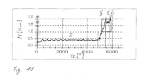
- the thread-armoring element 1; 1 'present invention requires at least a first screw-in torque M 1 due to its special design during its screwing or installation in an opening 50 of the component B after a basic screw-in torque M 0 . Since during installation of the threaded element 1; 1 'and its rotation angle is detected, the position of the threaded element 1, 1' in the opening 50 of the component B can be determined from the torque curve and the angle of rotation. This enables reliable process monitoring and quality assurance during installation already by using a standard screwdriver with torque and angle detection and evaluation.
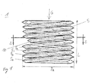
- the threaded element 1 according to Fig. 1 at least one narrowed helical winding 10.
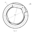
- Fig. 2 shows a plan view of the narrowed helical winding 10 from Fig. 1 ,
- the narrowed helical turn 10 includes at least two helical turn sections 12, 14.
- the turn sections 12, 14 include a secant 16, which is the otherwise circular helical winding 10 narrows radially inwardly (see Fig. 2A ). It is also preferred, instead of just one secant 16, to line up a plurality of secants 16 between the turn sections 12, 14, as shown in FIG Fig. 2C is shown. According to another embodiment, for example, two or more individual (see Fig. 2B ) or two or more times a plurality of secants 16 (not shown) by helical winding sections 12, 14 spaced from each other. It is also preferable to arrange more than two separate secants 16 or secant groups in the narrowed helical turn 10.
- Fig. 1 shows the thread-armoring element 1 with a certain length L.
- at least one constricted helical winding 10 is arranged in the central region relative to the length L of the thread-rolling element 1.
- one of the narrowed helical windings 10 is arranged within the last one to four helical windings 5 with respect to the gear direction G of the thread-rolling element 1. The advantage of this construction will be explained later in connection with the method of installing the threaded element 1.
- the thread-armoring element 1 has a plurality of successive helical turns 30, as they are, for example, in FIG Fig. 6 are shown.
- This plurality of helical turns 30 preferably comprises two to five turns 30. These are arranged at the beginning of the threaded element 1 in its direction of passage G.
- the helical turns 30 have a smaller diameter than the outer diameter D A of the thread-rolling element 1. In this way, the turns 30 are able to produce a greater adhesion, for example to a screw S, a mounting spindle 60 or other installation tool than the other helical turns 5 of the threaded element 1 with the outer diameter D A.
- the installation of the threaded element 1 in the component B is supported because the threaded element 1 is better kept on the screw S, the mounting spindle 60 or other installation tool. While a single one of these turns 30 would sufficiently secure the threaded element 1 to, for example, the screw S, by at least one additional turn 30, the grip of the thread-armoring element is achieved Elements 1 on the screw S additionally supported.
- the background is that, for example, when screwing the screw S with thread-armor element 1 into an opening 50 of the component B, the first turn 30 could encounter resistance. Such a resistance is, for example, a burr or a dirt in the internal thread 52 of the opening 50.
- the first turn 30 is blocked when screwing into the opening 50 and partially widened. This reduces the frictional connection between the screw S and the first turn 30.
- the at least one further winding 30 is arranged directly adjacent to the first turn 30. It is also preferable to arrange the at least one further winding 30 with several turns spaced from the first turn 30 (not shown). Likewise, it is preferable to provide successive spaced sets of turns 30. While one or more groups can be used, these each contain one to five turns 30.
- the thread-armoring element 1 according to Fig. 1 is by means of a screw S (see. Figures 5 and 6 ), a mounting spindle 60 (see. Fig. 9 ) or a similar installation tool in the opening 50 of the component B installed.
- the narrowed helical winding 10 is pressed by the screw S radially outward.
- the narrowed helical winding 10 extends beyond the outer diameter D A of the thread-rolling element 1 addition.
- This radially outward projection is dependent on the number and dimensioning of the secant 16.
- the increase of a screw-in torque M when entering the narrowed helical winding 10 into the internal thread 52 of the component B is specifically adjustable.
- the screw S is screwed with threaded element 1 in the direction G in the opening 50 of the component B, require the first helical turns 5 1 to 5 4 a basic screw-in torque M 0 .
- the screw-in torque M increases to a first screw-in torque M 1 , as soon as the narrowed helical winding 10 enters the internal thread 52 of the opening 50 with radially outwardly directed projection. Accordingly, the screw-in torque M continues to change in a defined manner when further narrowed helical turns 10 run with radially outwardly directed projection into the internal thread 52 of the opening 50.
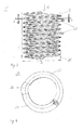
- FIG. 3 An alternative embodiment of a threaded element 1 'shows Fig. 3 , This threaded element 1 'need not be installed with a screw S or a mounting spindle 60 in the component B. Nevertheless, due to its design during installation, it provides the same change in screw-in torque as the threaded element 1 (see above).
- the thread-armoring elements 1 and 1 'of Fig. 1 and 3 differ only in that the threaded element 1 'uses a widened helical winding 20 instead of the narrowed helical winding 10. While the helical winding sections 22, 24 correspond in shape, arrangement and number to the various embodiments of the helical winding sections 12, 22, the at least one secant 16 has been replaced by at least one bulge 26.
- the bulge 26 extends radially outwardly beyond the outer diameter D A of the thread-rolling element 1 'addition. This radially outward projection is created by either one or a plurality of combined lobes 26 or by a plurality of separate lobes 26 or groups of lobes 26.
- the bulges 26 and the widened helical turns 20 are arranged in the same way as the secants 16 and the narrowed helical turns 10 (cf. Fig. 2A, 2B . 2C ), although this is not shown.
- the thread-armoring element 1 ' preferably also comprises the turns 30 which are narrower in comparison to the outside diameter D A. These in turn serve to support the thread-armoring element 1' on an installation tool by an increased adhesion as compared with the prior art.
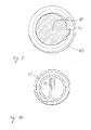
- each threaded element 1; 1 ' preferably each have a driving notch 42 or a driving pin 44 in the first turn 40 seen in the direction of movement G, as shown in FIGS FIGS. 9 and 10 are shown.
- the threaded elements 1, 1 ' are installed in the opening 50 of the component B.
- the opening 50 comprises the internal thread 52, which is threaded through the threaded element 1; 1 'is to be strengthened.
- the opening 50 has at its entrance preferably a cylindrical insertion surface 54 without internal thread 52. With the help of the insertion surface 54, the threaded element 1.1 'can first be aligned with respect to the opening 50. In addition, the insertion surface 54 supports the shrinkage of the threaded element 1; 1 ', because an initial tilting of the threaded element 1; 1 'in the opening 50 is avoided.
- Fig. 7c is a part of the threaded element 1 but not yet broken the secant 16 in the internal thread 52.
- the secant 16 was straight from the inside thread 52 recorded and in Fig. 7a the thread-armoring element 1 is completely installed in the opening 50 of the component B.
- step S 1 of the installation process first the thread-armoring element 1 is screwed into the internal thread 52, without a narrowed helical winding 10 being already screwed in. Due to the friction between the internal thread 52 and the threaded element 1 a basic screw-in torque M 0 is required to this screwing in accordance with Fig. 7c to realize.
- This first phase I is in Fig. 11 characterized. It requires an exemplary basic screw-in torque M 0 of 0.4 Nm over a rotation angle a of 4,800 °.
- a second phase II the secant 16 is screwed into the internal thread 52. Since the secant 16 generates a radially outward enlargement of the winding 10 on the screw S, the screwing-in torque M increases when the secant 16 enters the internal thread 52. Once the secant 16 is fully inserted into the internal thread 52, a plateau is achieved in the screw-in torque-angle curve. In this phase II thus increases the screw-in torque M from the basic screw-in torque M 0 to a first screw-in torque M 1 at the level of the plateau of the screw-in torque-rotation angle curve. This condition is in Fig. 7b shown.
- This first screw-in torque M 1 would also be detectable if a widened helical turn 20 of the thread-rolling element 1 'would run into the internal thread 52.
- the pitch is known.
- Pitch refers to the distance that a screw makes in one full turn inside the internal thread 52 would be offset. Multiplying the detected rotational angle a after its division by 360 ° with the pitch of the internal thread 52, one obtains the distance that has been added to the thread-armoring element 1 in the opening 50 inside. In addition, it is known at which position with respect to the length L of the thread-rolling element 1, the winding 10 is arranged with secant 16. The achievement of the first screw-in torque M, at a certain angle of rotation a at the end of phase II therefore provides a means of checking whether the threaded element 1 has properly entered the internal thread 52 and which position it has reached. At the end of Phase II (cf. Fig. 7b ), the product of pitch of the internal thread 52 and the quotient of angles of rotation a and 360 ° must correspond to the position of the coil 10 relative to the length L of the threaded element 1.
- step S 4 the screw-in torque M and the subsequent plateau value at a certain angle of rotation a can be used again to determine the position of the threaded element 1 in the opening 50 and check.
- the thread-armoring element 1,1 ' is completely installed, for example, the thread-armoring element 1, 1' runs on the bottom of the opening 50 or the head of the screw S settles on the surface of the component B. At this moment, the screw-in torque M steeply increases (phase IV) and exceeds a previously defined maximum torque threshold. When the torque threshold is exceeded, the installation process is automatically terminated according to a preferred embodiment. It is further preferred to recalculate, at this point, the position of the threaded element inside the aperture 50, based on the angle of rotation a, to confirm the end of the installation.
- the opening 50 of the component B preferably continuously the screw-in torque M and the rotation angle a detected.
- the process window P is exemplary in Fig. 11 illustrated.
- the process window P is defined by at least a minimum rotation angle a P1 and a minimum screw-in torque M P1 . It is furthermore preferred to additionally define a maximum angle of rotation a P2 and a maximum screw-in torque M P2 .
- the electric screwdriver or control connected thereto detects that the minimum limits a P1 and M P1 of the process window P have been exceeded, this is detected as reaching the minimum installation target. On this basis, according to one embodiment, the installation result of the threaded element 1; 1 'classified as "OK".
- the process window P is dimensioned in such a way and arranged in the screw-in torque-rotation angle space that within the process window P the screw-in torque M reaches the plateau value of the phase III.
- This plateau value signals the entry of the last narrowed helical turn 10 or the last widened helical turn 20 seen in the direction G in the internal thread 52 of the opening 50 at a certain angle of rotation a, as discussed in detail above.
- the process window P is preferably dimensioned such that the plateau value or the phase III lies completely within the process window P.
- the installation can also be classified as "OK” on this basis, because the last turn 10, 20 is completely integrated into the internal thread 52. If this plateau value of the phase III is not reached within the process window P or if this plateau value outside the process window P continues to angles of rotation higher than the maximum rotation angle limit a P2 , the installation is preferably classified as "not in order".
- the screwing-in torque M should exceed the defined maximum threshold value (see above) before reaching the maximum angle of rotation limit a P2 , ie within the process window P. If this is the case, the installation process is classified as "OK" and automatically terminated. If this maximum threshold value of the screw-in torque is not exceeded, the thread-armoring element 1; 1 'has not yet reached its final position and thus the installation can not be classified as "in order". It is preferably continued or canceled or the worker is signaled that the installation process leaves the process window P. In this case, the operator might want to monitor the further installation procedure instead of the automatic control.
- the end of the installation process is signaled to the worker, who then completes the installation procedure.
- Fig. 11 shown process window P to dimension differently and to arrange differently in the screw-in torque-rotation angle space.
- the limits of the process window P can be shifted so that in addition to the phases II, III, IV, a part of the phase I of the screw-in torque-rotation angle curve is included in the process window.
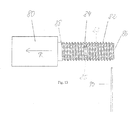
- the present invention also discloses a winding spindle 80, as according to a preferred embodiment in FIG Fig. 13 is shown.
- the winding spindle 80 comprises a fastening head, via which the winding spindle 80 can be fastened.
- This mounting head is connected, for example, with a motor or a gear portion such that the rotational movement of the motor or the gear portion is transferable to the winding spindle.
- the winding spindle 80 comprises a threaded portion 82.
- the threaded portion 82 is formed by a plurality of spindle threads 83.
- At least one spindle thread 83 comprises a depression 84 in the form of a secant or an elevation (not shown) in the form of a bulge, as later into the thread-armoring element 1; 1 'are formed.
- the thread comprise a plurality of contiguous recesses 84 or protrusions (not shown). It is also preferred that distributed over the length of the threaded portion 82 a plurality of spindle threads 83 each have a recess 84 or bulge or a plurality of recesses 84 or bulges.
- the winding spindle 80 serves to wind a wire 90 on the winding spindle 80, in particular the threaded portion 82, to a threaded armor element 1; 1 'produce. Therefore, when the wire 90 is wound on the threaded portion 82, it takes on the one hand the shape of the threaded portion 82 to form a wire helix. Further, the wire 90 to be wound is formed complementary to the existing dimple 84 or protrusions (not shown). Based on the number and arrangement of the recesses 84 or protrusions (not shown), thread-armoring elements 1, 1 'corresponding to FIGS. 1 to 4 and the above description. Thus, although not described or illustrated in detail herein, the threaded portion 82 may preferably be shaped complementary to the various preferred threaded armor elements 1,1 '(see above) to be manufactured using the winding mandrel 80.
- the threaded portion 82 also has a direction of travel R, indicated by the arrow in FIG Fig. 13 is indicated.
- a direction of travel R indicated by the arrow in FIG Fig. 13 is indicated.
- the wire 90 is moved in its perpendicular orientation to the longitudinal axis of the winding spindle 80 in the direction of travel R.
- the present invention discloses a manufacturing method of a thread-armor element 1; 1 'as described above.
- This manufacturing process preferably comprises the steps according to the flowchart in Fig. 14 on.
- To produce the threaded element 1, 1 ' is preferably the winding spindle 80 already described above Fig. 13 used, on which a wire 90 to be wound is wound up.
- a suitably shaped winding spindle 80 and a corresponding wire 90 are first selected and provided in step W1.
- the winding spindle 80 preferably has a different number and distribution of recesses 84 or bulges.
- the thread shape of the threaded portion 82 may vary, the later form of the threaded element 1; 1 'pretends.
- the end of the wire 90 to be wound (see FIG. Fig. 13 ) is attached to a first end 86 of the threaded portion 82 of the winding spindle 80. It is also conceivable to attach the end of the wire 90 to be wound on the end 88 of the threaded portion 82 in order to subsequently be able to wind it onto the threaded portion 82.
- the wire 90 is pressed into the first spindle thread 83 near the end 86 of the threaded portion 82. This force effect ensures that during the subsequent rotation of the winding spindle 80, the wire 90 is forced into the spindle threads 83 of the threaded portion 82. In this way, the coiled wire 90 takes on the shape of the threaded portion 82, which are defined by the individual spindle threads 83 with or without recesses 84 or bulges (not shown).
- the winding spindle 80 For winding the wire 90 on the threaded portion 82 of the wire 90 is perpendicular to the longitudinal axis of the winding spindle 80 aligned (see. Fig. 13 ). During winding of the wire 90 onto the threaded portion 82, the winding spindle 80 rotates about its longitudinal axis. At the same time, the winding spindle 80 is preferably moved counter to its direction of movement R in order to wind the wire 90 onto the threaded portion 82. Likewise, it is preferable to move the wire 90 in the direction R while the wire 90 is wound on the threaded portion 82. According to another preferred embodiment, it is preferable to simultaneously move the winding spindle 80 counter to the direction of movement R, while the wire 90 is moved in the direction of movement R.
- the shape of the individual spindle threads 83 is impressed in the wire 90.
- the at least one recess 84 is a secant 16 or by the increase (not shown), the bulge 26 in a corresponding number and distribution of the recesses 84 and elevations on the threaded portion 82 in the wire helix of the threaded element 1; 1 'generated.
- step W4 the wire 90 projecting perpendicularly to the longitudinal axis of the winding spindle 80 is severed to form the thread-armoring element 1; 1 'form.
- This separation is realized, for example, by cutting, punching, shearing or breaking at a previously impressed predetermined breaking point of the wire 90.
- This separation in step W4 is preferably carried out at the end 88 of the threaded section 82.
- step W5 preferably the unwinding of the thread-armoring element 1; 1 'from the threaded portion 82 and the winding spindle 80.
Abstract
Description
Die vorliegende Erfindung betrifft ein gewindepanzerndes Element, eine Schraube mit gewindepanzerndem Element, ein Installationsverfahren für ein gewindepanzerndes Element in einer Öffnung eines Bauteils sowie das Bauteil mit installiertem gewindepanzerndem Element.The present invention relates to a threaded element, a screw with a threaded element, an installation method for a threaded element in an opening of a component as well as the component with installed thread-armor element.
Gewindepanzernde Elemente, die auch als Drahtgewindeeinsätze bezeichnet werden, sind allgemein im Stand der Technik bekannt. So gibt es unterschiedlichste Materialgestaltungen der gewindepanzernden Elemente, die in Abhängigkeit von dem jeweiligen Anwendungsgebiet variieren. Des Weiteren variieren die gewindepanzernden Elemente in ihrer Form, um unterschiedliche Einbauvarianten zu unterstützen.Thread-wrapping elements, also referred to as wire thread inserts, are generally known in the art. Thus, there are very different material designs of the thread-armoring elements, which vary depending on the respective field of application. Furthermore, the thread-armor elements vary in shape to support different installation variants.
Zum Einbringen des gewindepanzernden Elements in eine Öffnung mit oder ohne Aufnahmegewinde eines Bauteils sind zwei Montagearten üblich. Bei der einen Montageart ist der wendelförmige Draht des gewindepanzernden Elements mit einer Mitnahme-Kerbe versehen. Über diese Mitnahme-Kerbe schleppt ein Einbauwerkzeug das gewindepanzernde Element mit und dreht es in das Aufnahmegewinde der Öffnung des Bauteils ein. Dies ist beispielsweise in
Gewindepanzemde Elemente weisen zudem bezogen auf ihren Innendurchmesser verkleinerte Windungen auf, die als sogenannte Schrauben-Sicherungen (screw-lock) dienen.
Es ist die Aufgabe vorliegender Erfindung, ein gewindepanzerndes Element bereitzustellen, das im Vergleich zum Stand der Technik aufgrund seiner Ausgestaltung die Installation in einem Bauteil unterstützt und vereinfacht. In gleicher Weise soll ein entsprechendes Installationsverfahren für derart gestaltete gewindepanzernde Elemente bereitgestellt werden.It is the object of the present invention to provide a threaded armor element which, compared to the prior art due to its design, assists and simplifies the installation in one component. In the same way, a corresponding installation method for such designed threaded armor elements should be provided.
Die obige Aufgabe wird durch ein gewindepanzerndes Element gemäß den Ansprüchen 1 und 7, eine Schraube mit gewindepanzerndem Element gemäß Anspruch 13, ein Installationsverfahren für das gewindepanzernde Element gemäß Anspruch 14 sowie durch ein Bauteil mit gewindepanzerndem Element gemäß Anspruch 19 gelöst. Vorteilhafte Ausgestaltungen, bevorzugte Ausführungsformen und Weiterentwicklungen vorliegender Erfindung gehen aus der Beschreibung, den Ansprüchen und den anhängenden Zeichnungen hervor.The above object is achieved by a thread-armor element according to
Erfindungsgemäß weist das gewindepanzernde Element in Form eines Drahtgewindeeinsatzes die folgenden Merkmale auf: a) eine Mehrzahl von aufeinanderfolgenden wendelförmigen Windungen, deren radiale Innenseite, vorzugsweise auch deren radialeAußenseite, in der Form an ein Gewinde angepasst ist, in der b) mindestens eine verengte wendelförmige Windung aus mindestens zwei wendelförmigen Windungsabschnitten besteht, die eine oder eine Mehrzahl aufeinanderfolgender Sekanten einschließen, die die verengte wendelförmige Windung radial einwärts verengt/verengen.According to the invention, the thread-armoring element in the form of a wire thread insert has the following features: a) a plurality of successive helical turns whose radially inner side, preferably also their radial outer side, is adapted in the form to a thread, in which b) at least one constricted helical turn consists of at least two helical turn sections which include one or a plurality of successive secants that narrow / narrow the constricted helical turn radially inwardly.
Das erfindungsgemäße gewindepanzernde Element weist diese spezielle Form auf, um gemeinsam mit einer Schraube oder einer Einbauspindel auf vorteilhafte Weise in eine Öffnung eines Bauteils installiert zu werden. Sobald das gewindepanzernde Element auf der Schraube oder der Einbauspindel oder allgemein einem Einbauwerkzeug vormontiert worden ist, wird die verengte wendelförmige Windung, beispielsweise durch die Schraube, radial nach außen gedrückt. Dieses radiale nach außen Drücken der verengten wendelförmigen Windung des gewindepanzernden Elements bewirkt, dass zumindest ein Teil der verengten wendelförmigen Windung radial nach außen über den Außendurchmesser des übrigen gewindepanzernden Elements hinaus ragt. Aufgrund dieses radial nach außen gerichteten Überstands wird während des Eindrehens der Schraube mit gewindepanzerndem Element in eine Öffnung eines Bauteils ein bestimmtes erhöhtes Drehmoment im Vergleich zum vorhergehenden Teil der Schraube mit gewindepanzerndem Element erforderlich sein. Erkennt man während der Installation der Schraube mit diesem gewindepanzernden Element den Anstieg des Drehmoments, kann man auf diese Weise überwachen, bis zu welcher Position das gewindepanzernde Element bereits in die Öffnung des Bauteils eingeschraubt oder eingedreht worden ist.The thread-armoring element according to the invention has this special shape in order to be installed together with a screw or a mounting spindle in an advantageous manner in an opening of a component. Once the threaded element has been preassembled on the screw or the mounting spindle, or generally an installation tool, the restricted helical winding is forced radially outward, for example by the screw. This radially outward urging of the narrow helical coil of the threaded element causes at least a portion of the narrow helical coil to protrude radially outwardly beyond the outer diameter of the remainder of the threaded element. Due to this radially outward supernatant is during the screwing of the screw with threaded element into an opening of a component a certain increased torque compared to the previous part of the screw with thread-armor element may be required. If one recognizes during the installation of the screw with this threaded element the increase in torque, you can monitor in this way, up to which position the threaded element has already been screwed or screwed into the opening of the component.
Um bei der Installation des gewindepanzernden Elements einen verlässlichen Anstieg des Einbau-Drehmoments zu erzielen, umfasst das gewindepanzernde Element bevorzugt mindestens eine verengte wendelförmige Windung mit mindestens drei wendelförmigen Windungsabschnitten, die an mindestens zwei Stellen eine oder eine Mehrzahl aufeinanderfolgender Sekanten einschließen. Es ist ebenfalls bevorzugt, dass mindestens zwei verengte wendelförmige Windungen vorgesehen sind, die in Längsrichtung des gewindepanzernden Elements voneinander beabstandet angeordnet sind. Diese spezielle Ausführungsform gewährleistet, dass zwei oder mehrere Anstiege bei der Erfassung des Einbau-Drehmoments der Schraube mit gewindepanzernden Element erkennbar sind, um unterschiedliche Einbaupositionen des gewindepanzernden Elements in der Öffnung des Bauteils für den Werker sichtbar zu machen.In order to achieve a reliable increase in built-in torque during installation of the threaded element, the threaded element preferably includes at least one narrowed helical turn having at least three helical turn sections including one or more consecutive secants at at least two locations. It is also preferred that at least two constricted helical turns are provided which are spaced apart in the longitudinal direction of the threaded element. This particular embodiment ensures that two or more increases in the detection of the installation torque of the threaded element bolt are apparent to visualize different mounting positions of the threaded element in the opening of the component for the worker.
Gemäß einer weiteren Ausführungsform ist eine der verengten wendelförmigen Windungen innerhalb der letzten ein bis vier wendelförmigen Windungen bezogen auf die Gangrichtung des gewindepanzernden Elements angeordnet. Gemäß einer weiteren Ausgestaltung ist eine verengte wendelförmige Windung im mittleren Bereich bezogen auf eine Länge des gewindepanzernden Elements angeordnet.According to another embodiment, one of the narrowed helical turns is arranged within the last one to four helical turns with respect to the direction of travel of the threaded element. According to a further embodiment, a narrowed helical winding is arranged in the middle region relative to a length of the thread-armoring element.
Erfindungsgemäß wird ein weiteres gewindepanzerndes Element vorgeschlagen, das auch bei Installation ohne Schraube oder Einbauspindel die gleiche Funktion wie das oben beschriebene gewindepanzernde Element gewährleistet. Dieses gewindepanzernde Element in Form eines Drahtgewindeeinsatzes weist die folgenden Merkmale auf: eine Mehrzahl von aufeinanderfolgenden wendelförmigen Windungen, deren radiale Innenseite, vorzugsweise auch deren radiale Außenseite in der Form an ein Gewinde angepasst ist, in der b) mindestens eine aufgeweitete wendelförmige Windung aus mindestens zwei wendelförmigen Windungsabschnitten besteht, die eine oder eine Mehrzahl aufeinanderfolgender Ausbuchtungen einschließen, die die aufgeweitete wendelförmige Windung radial auswärts aufweitet/aufweiten.According to the invention, a further threaded armor element is proposed which ensures the same function as the above-described threaded armor element even when installed without a screw or mounting spindle. This thread-armoring element in the form of a wire thread insert has the following features: a plurality of successive helical turns whose radial inside, preferably also their radial outer side in the form is adapted to a thread, in which b) at least one widened helical turn of at least two helical winding sections which include one or a plurality of successive lobes which expand / widen the widened helical turn radially outward.
Im Vergleich zum oben beschriebenen gewindepanzernden Element mit verengter wendelförmiger Windung werden die verengten wendelförmigen Windungen durch aufgeweitete wendelförmige Windungen ersetzt. Diese aufgeweiteten wendelförmigen Windungen nutzen anstelle von Sekanten eine oder eine Mehrzahl von radial nach außen gerichteten Ausbuchtungen, die über den Außendurchmesser des übrigen gewindepanzernden Elements hinaus ragen. Auf diese Weise erzeugen bereits diese aufgeweiteten wendelförmigen Windungen eine Steigerung des Einbau-Drehmoments, sobald sie in die Öffnung des Bauteils eingeschraubt werden. Daraus folgt, dass ein Anstieg des Einbau-Drehmoments des gewindepanzernden Elements auch ohne eine vorinstallierte Schraube oder Einbauspindel generierbar ist.Compared with the above-described helical element with narrow helical winding, the narrowed helical turns are replaced by widened helical turns. These flared helical turns use, instead of secants, one or a plurality of radially outward bulges that protrude beyond the outer diameter of the remainder of the threaded element. In this way, even these widened helical turns generate an increase in the installation torque as soon as they are screwed into the opening of the component. It follows that an increase in the installation torque of the threaded element can be generated without a pre-installed screw or mounting spindle.
In bevorzugter Ausgestaltung dieses gewindepanzernden Elements mit aufgeweiteter wendelförmiger Windung umfasst die mindestens eine aufgeweitete wendelförmige Windung mindestens drei wendelförmige Windungsabschnitte, die an mindestens zwei Stellen eine oder eine Mehrzahl aufeinanderfolgender Ausbuchtungen einschließen. Es ist zudem bevorzugt, dass mindestens zwei aufgeweitete wendelförmige Windungen in dem gewindepanzernden Element vorgesehen sind, die in Längsrichtung des gewindepanzernden Elements voneinander beabstandet angeordnet sind. In weiterer bevorzugter Ausgestaltung dazu ist eine der aufgeweiteten wendelförmigen Windungen innerhalb der letzten ein bis vier wendelförmigen Windungen bezogen auf die Gangrichtung des gewindepanzernden Elements angeordnet, während eine weitere aufgeweitete wendelförmige Windung bevorzugt im mittleren Bereich bezogen auf eine Länge des gewindepanzernden Elements angeordnet ist.In a preferred embodiment of this helical widening element having a widened helical turn, the at least one widened helical turn comprises at least three helical turn sections which include one or a plurality of successive lobes at at least two locations. It is also preferred that at least two widened helical turns are provided in the thread-armoring element, which are spaced apart in the longitudinal direction of the thread-armoring element. In a further preferred embodiment, one of the widened helical turns is arranged within the last one to four helical turns relative to the direction of travel of the thread-armoring element, while another widened helical turn is preferably arranged in the central region relative to a length of the thread-armoring element.
Des Weiteren offenbart vorliegende Erfindung ein Installationsverfahren für eine Schraube mit gewindepanzerndem Element oder eine Einbauspindel mit gewindepanzerndem Element oder ein Einbauwerkzeug mit einem gewindepanzernden Element in einer Öffnung mit Innengewinde eines Bauteils, wobei eine Ganghöhe pro Umdrehung des Innengewindes bekannt ist. Dieses Installationsverfahren weist die folgenden Schritte auf: a) Einschrauben der Schraube mit gewindepanzerndem Element, der Einbauspindel mit gewindepanzerndem Element oder des Einbauwerkzeugs mit gewindepanzerndem Element in das Innengewinde der Öffnung des Bauteils, b) Erfassen eines Einschraub-Drehmoments und eines Drehwinkels des gewindepanzernden Elements während des Einschraubens, c) Bestimmen einer Position des gewindepanzernden Elements in der Öffnung aus einem ersten zurückgelegten Drehwinkel nach einem ersten Anstieg des Einschraub-Drehmoments von einem Grund-Einschraub-Drehmoment auf ein erstes Einschraub-Drehmoment, das ein Einlaufen der verengten wendelförmigen Windung des gewindepanzernden Elements oder der aufgeweiteten wendelförmigen Windung des gewindepanzernden Elements in die Öffnung signalisiert, und der Ganghöhe des Gewindes.Further, the present invention discloses an installation method for a screw with a screw-driving element or a mounting spindle with a threaded element or a fitting tool with a threaded element in an internally threaded opening of a component, wherein a pitch per revolution of the internal thread is known. This installation method comprises the following steps: a) screwing the screw with the thread-rolling element, the threaded-armature mounting spindle or the thread-piercing element installation tool into the internal thread of the opening of the component, b) detecting a screw-in torque and a twist angle of the threaded element during screwing, c) determining a position of the threaded element in the opening from a first returned angle of rotation after a first increase in the screwing torque of a basic screwing torque to a first screw-in torque, which signals a shrinkage of the narrowed helical winding of the threaded element or the widened helical turn of the threaded element in the opening, and the pitch of the thread.
Das erfindungsgemäße Installationsverfahren basiert darauf, dass beim Installieren des gewindepanzernden Elements sowohl der Drehwinkel wie auch das Einschraub-Drehmoment erfasst werden. Mit Hilfe der Erfassung des Einschraub-Drehmoments ist feststellbar, wann die auf der Schraube oder der Einbauspindel sitzende verengte wendelförmige Windung oder wann die aufgeweitete wendelförmige Windung in die Öffnung des Bauteils eingedreht wird, weil dabei ein Anstieg des Einschraub-Drehmoments stattfindet. Da aufgrund der Formgebung des gewindepanzernden Elements die Zunahme des Einschraub-Drehmoments definiert einstellbar ist, ist während des Installationsverfahrens mit Sicherheit erkennbar, wann dieser spezielle Bereich des gewindepanzernden Elements in die Öffnung des Bauteils eintritt. Erfasst man nun ab diesem Anstieg des Einschraub-Drehmoments den zurückgelegten Drehwinkel des gewindepanzernden Elements, weiß man, wie weit das gewindepanzernde Element bereits in der Öffnung des Bauteils installiert ist. Die Position des gewindepanzernden Elements ergibt sich dabei aus dem Produkt des Drehwinkels und der Ganghöhe des Innengewindes der Öffnung des Bauteils.The installation method according to the invention is based on the fact that when installing the threaded element, both the angle of rotation and the screw-in torque are detected. With the help of the detection of the screw-in torque can be determined when the seated on the screw or the mounting spindle constricted helical winding or when the widened helical winding is screwed into the opening of the component, because there is an increase in the screwing torque. Since the increase in screw-in torque can be set in a defined manner due to the shape of the threaded element, it is certainly possible during the installation process to detect when this particular area of the threaded element enters the opening of the component. If, from this increase in the screwing-in torque, the distance covered by the angle of rotation of the thread-rolling element is determined, one knows how far the thread-arming element is already installed in the opening of the component. The position of the threaded element results from the product of the angle of rotation and the pitch of the internal thread of the opening of the component.
Zur weiteren Ausgestaltung des Installationsverfahrens ist es bevorzugt, ein maximales Drehmoment zu definieren und das Einschrauben des gewindepanzernden Elements bei Erreichen des maximalen Drehmoments zu beenden. In diesem Zusammenhang dient das maximale Drehmoment bzw. eine entsprechend zu definierende Drehmoment-Schwelle dazu, beispielsweise eine Anlage des gewindepanzernden Elements an einem Boden der Öffnung des Bauteils zu erfassen. In gleicher Weise ist auf diese Art erkennbar, dass der Kopf der Schraube mit gewindepanzerndem Element auf dem Bauteil aufliegt bzw. aufläuft.For further embodiment of the installation method, it is preferable to define a maximum torque and to end the screwing of the threaded element upon reaching the maximum torque. In this context, the maximum torque or a corresponding torque threshold to be defined serves, for example, to detect a contact of the threaded element at a bottom of the opening of the component. In the same way it can be seen in this way that the head of the screw with thread-armor element rests or runs on the component.
Sollte das gewindepanzernde Element mit Schraube mehrere verengte wendelförmige Windungen aufweisen oder das gewindepanzernde Element mehrere aufgeweitete wendelförmige Windungen aufweisen, ist es bevorzugt, einen zweiten Anstieg des Einschraub-Drehmoments zu erfassen, welcher ein Einlaufen einer weiteren verengten oder aufgeweiteten wendelförmigen Windung des gewindepanzernden Elements in die Öffnung des Bauteils signalisiert, um auf dieser Grundlage die Position des gewindepanzernden Elements in der Öffnung des Bauteils zu bestimmen.Should the threaded element with screw have a plurality of narrow helical turns, or the threaded element have a plurality of flared helical turns, it is preferable to detect a second increase in screw-in torque which causes a further narrowed or widened helical turn of the threaded element to enter Opening of the component signals to on this basis to determine the position of the threaded element in the opening of the component.
Des Weiteren umfasst vorliegende Erfindung ein Bauteil mit einer Öffnung mit Innengewinde und einem darin installierten gewindepanzernden Element oder einem gewindepanzernden Element mit Schraube. Um die Installation des gewindepanzernden Elements in der Öffnung des Bauteils zu unterstützen, ist bevorzugt am Eingang der Öffnung eine zylindrische Einruhrfläche ohne Innengewinde vorgesehen. Diese zylindrische Einführfläche erleichtert das Ansetzen und Ausrichten des gewindepanzernden Elements in Bezug auf die Öffnung, um das nachfolgende Einschrauben zu erleichtern.Furthermore, the present invention comprises a component having an internal threaded opening and a threaded armoring element or screw threaded element installed therein. In order to assist the installation of the threaded element in the opening of the component, a cylindrical locking surface without internal thread is preferably provided at the entrance of the opening. This cylindrical insertion surface facilitates the attachment and alignment of the threaded element with respect to the opening to facilitate subsequent screwing.
Die vorliegende Erfindung umfasst zudem eine Wickelspindel zum Herstellen eines gewindepanzernden Elements aus einem Draht. Die Wickelspindel weist die folgenden Merkmale auf: einen Befestigungskopf, über den die Wickelspindel befestigbar ist, und einen Gewindeabschnitt, der mindestens eine Vertiefung in Form einer Sekante oder eine Erhöhung in Form einer Ausbuchtung aufweist. Der Gewindeabschnitt der Wickelspindel umfasst eine Mehrzahl von Gewindegängen. Bevorzugt sind innerhalb eines Gewindegangs des Gewindeabschnitts eine Vertiefung oder eine Erhöhung oder eine Mehrzahl aneinandergrenzender Vertiefungen oder Erhöhungen angeordnet. Es ist weiter bevorzugt, mehrere einzelne Vertiefungen oder Erhöhungen oder mehrmals eine Mehrzahl von Vertiefungen oder Erhöhungen in axialer Richtung entlang des Gewindeabschnitts verteilt anzuordnen. Gemäß einer anderen Ausführungsform ist die mindestens eine Vertiefung oder Erhöhung oder Mehrzahl von Vertiefungen oder Erhöhungen durch zwei Spindelgewindeabschnitte eingeschlossen.The present invention also comprises a winding spindle for producing a thread-armoring element from a wire. The winding spindle has the following features: a fastening head, by way of which the winding spindle can be fastened, and a threaded portion which has at least one recess in the form of a secant or an elevation in the form of a bulge. The threaded portion of the winding spindle comprises a plurality of threads. Preferably, within a thread of the threaded portion, a recess or an elevation or a plurality of adjacent depressions or elevations are arranged. It is further preferred to arrange a plurality of individual depressions or elevations or multiple times a plurality of depressions or elevations distributed in the axial direction along the threaded portion. According to another embodiment, the at least one recess or elevation or plurality of depressions or elevations is enclosed by two spindle thread sections.
Die vorliegende Erfindung offenbart zudem ein Herstellungsverfahren für ein gewindepanzerndes Element, insbesondere ein gewindepanzerndes Element, wie es oben beschrieben worden ist, das die folgenden Schritte aufweist: Ansetzen eines zu wickelnden Drahts an einer Wickelspindel mit mindestens einer Vertiefung oder Erhöhung in einem Gewindeabschnitt, vorzugsweise eine Wickelspindel gemäß obiger Beschreibung, Drehen der Wickelspindel derart, dass der zu wickelnde Draht auf die Wickelspindel aufgewickelt wird und die mindestens eine Vertiefung oder Erhöhung im Gewindeabschnitt mindestens eine Sekante oder Ausbuchtung ausformt, und Abtrennen des zu wickelnden Drahts von dem auf die Wickelspindel gewickelten Draht, so dass ein gewindepanzerndes Element vorliegt, und Abspindeln des gewindepanzernden Elements von der Wickelspindel.The present invention also discloses a manufacturing method for a threaded element, in particular a threaded element as described above, comprising the following steps: attaching a wire to be wound to a winding spindle having at least one recess or elevation in a threaded portion, preferably one Winding spindle as described above, rotating the winding spindle such that the wire to be wound is wound onto the winding spindle and the at least one recess or elevation in the threaded portion forms at least one secant or bulge, and severing the wire to be wound from the wound on the winding spindle wire, so that a thread-armor element is present, and unscrewing the thread-armoring element from the winding spindle.
Bevorzugte Ausführungsformen vorliegender Erfindung werden unter Bezugnahme auf die begleitende Zeichnung näher erläutert. Es zeigen:
- Fig. 1
- eine bevorzugte Ausführungsform des gewindepanzernden Elements mit einer verengten wendelförmigen Windung,
- Fig. 2A
- eine Schnittansicht entlang der Linie aus
Fig. 1 , - Fig. 2B
- eine Schnittansicht entlang der Linie aus
Fig. 1 einer weiteren bevorzugten Ausführungsform des gewindepanzernden Elements mit mehreren in axialer Richtung verteilt angeordneten einzelnen verengten wendelförmigen Windungen, - Fig. 2C
- eine Schnittansicht entlang der Linie aus
Fig. 1 einer weiteren bevorzugten Ausführungsform des gewindepanzernden Elements mit einer Mehrzahl aneinander angrenzender verengter wendelförmiger Windungen, - Fig. 3
- eine bevorzugte Ausführungsform des gewindepanzernden Elements mit zwei voneinander beabstandeten aufgeweiteten wendelförmigen Windungen,
- Fig. 4
- eine Schnittdarstellung entlang der Linie aus
Fig. 3 , - Fig. 5
- eine Schraube mit vormontiertem gewindepanzerndem Element gemäß
Fig. 1 , - Fig. 6
- eine bevorzugte Ausführungsform einer Schraube mit gewindepanzerndem Element, das an seinem Schraubenkopf abgewandten Ende eine Mehrzahl von in ihrem Durchmesser verengten Windungen aufweist,
- Fig. 7
- unterschiedliche Installationsstufen eines gewindepanzernden Elements in einer Öffnung eines Bauteils,
- Fig. 8
- ein bevorzugtes Bauteil mit Öffnungen mit Innengewinde und Einführfläche,
- Fig. 9
- eine bevorzugtes Ende eines gewindepanzernden Elements mit Mitnahme-Kerbe,
- Fig. 10
- ein bevorzugtes Ende eines gewindepanzernden Elements mit Mitnahme-Zapfen,
- Fig. 11
- beispielhafte Darstellung eines Einschraub-Drehmoments in Abhängigkeit vom Drehwinkel des gewindepanzernden Elements während seiner Installation in der Öffnung des Bauteils,
- Fig. 12
- Flussdiagramm des bevorzugten Installationsverfahrens vorliegender Erfindung,
- Fig. 13
- eine bevorzugte Ausführungsform einer Wickelspindel zur Herstellung des gewindepanzernden Elements und
- Fig. 14
- Flussdiagramm des bevorzugten Herstellungsverfahrens des gewindepanzernden Elements.
- Fig. 1
- a preferred embodiment of the threaded element with a narrowed helical winding,
- Fig. 2A
- a sectional view taken along the line
Fig. 1 . - Fig. 2B
- a sectional view taken along the line
Fig. 1 a further preferred embodiment of the thread-armoring element with a plurality of individual narrowed helical turns distributed in the axial direction, - Fig. 2C
- a sectional view taken along the line
Fig. 1 a further preferred embodiment of the thread-armoring element with a plurality of contiguous narrowed helical turns, - Fig. 3
- a preferred embodiment of the threaded element with two spaced-apart widened helical turns,
- Fig. 4
- a sectional view along the line
Fig. 3 . - Fig. 5
- a screw with preassembled thread-armor element according to
Fig. 1 . - Fig. 6
- a preferred embodiment of a screw with thread-armoring element, the end facing away from its screw head has a plurality of narrowed in diameter turns,
- Fig. 7
- different installation stages of a threaded element in an opening of a component,
- Fig. 8
- a preferred component with openings with internal thread and insertion surface,
- Fig. 9
- a preferred end of a threaded element with driving notch,
- Fig. 10
- a preferred end of a threaded element with driving pin,
- Fig. 11
- exemplary representation of a screw-in torque as a function of the angle of rotation of the threaded element during its installation in the opening of the component,
- Fig. 12
- Flowchart of the preferred installation method of the present invention
- Fig. 13
- a preferred embodiment of a winding spindle for producing the threaded element and
- Fig. 14
- Flowchart of the preferred manufacturing process of the threaded element.
Das erfindungsgemäße gewindepanzernde Element 1; 1' hat die Form einer Drahtwendel, die als Schraubenfeder ausgeführt ist. Die Drahtwendel besteht aus einer Mehrzahl von aufeinanderfolgenden wendelförmigen Windungen 5. Die wendelförmigen Windungen 5 und somit das gesamte gewindepanzernde Element 1:1' besitzt einen Innendurchmesser und einen Außendurchmesser DA. Zudem hat das gewindepanzernde Element 1; 1' je nach Anwendungsfall eine bestimmte Länge L.The thread-
Die wendelförmigen Windungen 5 haben vorzugsweise einen diamantförmigen Querschnitt. Dadurch wird an der radialen Innen- und Außenseite der wendelförmigen Windungen 5 jeweils eine an ein Gewinde angepasste Form vorgegeben. Es ist ebenfalls bevorzugt, dass lediglich die radiale Innenseite des gewindepanzernden Elements 1; 1' eine Gewindeform vorgibt. Die radiale Außenseite des gewindepanzernden Elements 1; 1' ist in diesem Fall beliebig ausgebildet und realisiert beispielsweise eine Verankerungs- oder Materialverdrängungsfunktion im Material eines Bauteils B.The helical turns 5 preferably have a diamond-shaped cross-section. As a result, a shape adapted to a respective thread is predetermined on the radial inside and outside of the
Die Drahtwendel besteht bevorzugt aus einem Federstahl oder einem anderen elastischen Werkstoff hoher Festigkeit.The wire helix is preferably made of a spring steel or other elastic material of high strength.
Das gewindepanzernde Element 1; 1' vorliegender Erfindung erfordert aufgrund seiner speziellen Ausgestaltung während seines Einschraubens bzw. Einbaus in eine Öffnung 50 des Bauteils B nach einem Grund-Einschraub-Drehmoment M0 mindestens ein erstes Einschraub-Drehmoment M1. Da während des Einbaus des gewindepanzernden Elements 1; 1' auch sein Drehwinkel erfasst wird, ist aus dem Drehmoment-Verlauf und dem Drehwinkel die Position des gewindepanzernden Elements 1, 1' in der Öffnung 50 des Bauteils B bestimmbar. Dies ermöglicht eine verlässliche Prozessüberwachung und Qualitätssicherheit während der Installation bereits durch den Einsatz eines Standard-Schraubgeräts mit Drehmoment- und Drehwinkel-Erfassung und -Auswertung. Zu diesem Zweck weist das gewindepanzernde Element 1 gemäß
Die verengte wendelförmige Windung 10 umfasst mindestens zwei wendelförmige Windungsabschnitte 12, 14. Die Windungsabschnitte 12, 14 schließen eine Sekante 16 ein, die die sonst kreisförmige wendelförmige Windung 10 radial einwärts verengt (siehe
Gemäß einer weiteren optionalen Ausgestaltung weist das gewindepanzernde Element 1 eine Mehrzahl von aufeinanderfolgenden wendelförmigen Windungen 30 auf, wie sie beispielsweise in
Das gewindepanzernde Element 1 gemäß
Wird nun die Schraube S mit gewindepanzerndem Element 1 in Gangrichtung G in die Öffnung 50 des Bauteils B eingeschraubt, erfordern die ersten wendelförmigen Windungen 51 bis 54 ein Grund-Einschraub-Drehmoment M0. Das Einschraub-Drehmoment M steigt auf ein erstes Einschraub-Drehmoment M1, sobald die verengte wendelförmige Windung 10 mit radial auswärts gerichtetem Überstand in das Innengewinde 52 der Öffnung 50 einläuft. Entsprechend verändert sich das Einschraub-Drehmoment M weiter in definierter Weise, wenn weitere verengte wendelförmige Windungen 10 mit radial auswärts gerichtetem Überstand in das Innengewinde 52 der Öffnung 50 einlaufen.Now, if the screw S is screwed with threaded
Eine alternative Ausgestaltung eines gewindepanzernden Elements 1' zeigt
Die gewindepanzernden Elemente 1 und 1' der
Wird das gewindepanzernde Element 1' in das Innengewinde 52 der Öffnung 50 des Bauteils B eingeschraubt, erzeugt die mindestens eine aufgeweitete wendelförmige Windung 20 den gleichen Effekt wie die verengte wendelförmige Windung 10 nach Vorinstallation auf der Schraube S. Daher wird für weitere Details auf die obigen Ausführungen zum gewindepanzernden Element 1 verwiesen.When the threaded element 1 'is screwed into the internal thread 52 of the
Zur Unterstützung der Installation der gewindepanzernden Elemente 1; 1' weisen sie bevorzugt jeweils in der in Gangrichtung G gesehenen ersten Windung 40 eine Mitnahme-Kerbe 42 oder einen Mitnahme-Zapfen 44 auf, wie sie in den
Die gewindepanzernden Elemente 1, 1' werden in der Öffnung 50 des Bauteils B installiert. Die Öffnung 50 umfasst das Innengewinde 52, das durch das gewindepanzernde Element 1; 1' verstärkt werden soll. Die Öffnung 50 weist an ihrem Eingang vorzugsweise eine zylindrische Einführfläche 54 ohne Innengewinde 52 auf. Mit Hilfe der Einführfläche 54 kann das gewindepanzernde Element 1,1' zunächst in Bezug auf die Öffnung 50 ausgerichtet werden. Zudem unterstützt die Einführfläche 54 das Einlaufen des gewindepanzernden Elements 1; 1', weil ein anfängliches Verkanten des gewindepanzernden Elements 1; 1' in der Öffnung 50 vermieden wird.The threaded
Anhand von
In den
In
Im Schritt S 1 des Installationsverfahrens wird zunächst das gewindepanzernde Element 1 in das Innengewinde 52 eingeschraubt, ohne dass bereits eine verengte wendelförmige Windung 10 eingeschraubt wird. Aufgrund der Reibung zwischen Innengewinde 52 und dem gewindepanzernden Element 1 ist ein Grund-Einschraub-Drehmoment M0 erforderlich, um dieses Einschrauben gemäß
Wie man anhand des Diagramms in
In einer zweiten Phase II wird die Sekante 16 in das Innengewinde 52 eingeschraubt. Da die Sekante 16 auf der Schraube S eine radial auswärtige Vergrößerung der Windung 10 erzeugt, nimmt das Einschraub-Drehmoment M beim Einlaufen der Sekante 16 in das Innengewinde 52 zu. Sobald die Sekante 16 vollständig in das Innengewinde 52 eingelaufen ist, wird ein Plateau in der Einschraub-Drehmoment-Drehwinkel-Kurve erreicht. In dieser Phase II steigt somit das Einschraub-Drehmoment M von dem Grund-Einschraub-Drehmoment M0 auf ein erstes Einschraub-Drehmoment M1 auf Höhe des Plateaus der Einschraub-Drehmoment-Drehwinkel-Kurve. Dieser Zustand ist in
Dieses erste Einschraub-Drehmoment M1 wäre ebenfalls erfassbar, wenn eine aufgeweitete wendelförmige Windung 20 des gewindepanzernden Elements 1' in das Innengewinde 52 einlaufen würde.This first screw-in torque M 1 would also be detectable if a widened
Vom Innengewinde 52 des Bauteils B ist die Ganghöhe bekannt. Ganghöhe bezeichnet die Strecke, die eine Schraube bei einer vollständigen Umdrehung innerhalb des Innengewindes 52 versetzt werden würde. Multipliziert man den erfassten Drehwinkel a nach dessen Division durch 360° mit der Ganghöhe des Innengewindes 52, erhält man die Strecke, die das gewindepanzernde Element 1 in die Öffnung 50 hinein versetzt worden ist. Zudem ist bekannt, an welcher Position bezogen auf die Länge L des gewindepanzernden Elements 1 die Windung 10 mit Sekante 16 angeordnet ist. Das Erreichen des ersten Einschraub-Drehmoments M, bei einem bestimmten Drehwinkel a am Ende von Phase II liefert daher eine Überprüfungsmöglichkeit, ob das gewindepanzernde Element 1 richtig in das Innengewinde 52 eingelaufen ist und welche Position es erreicht hat. Am Ende von Phase II (vgl.
Wird der Einschraub-Vorgang fortgesetzt und tritt zunächst keine weitere Windung 10 in das Innengewinde 52 ein, bleibt das Einschraub-Drehmoment M auf dem Plateauwert des ersten Einschraub-Drehmoments M1. Würde eine weitere Windung 10 in das Innengewinde 52 einlaufen, würde ein weiterer Anstieg des Einschraub-Drehmoments M bis zu einem zweiten Einschraub-Drehmoment M2 in Analogie zu Phase II erfasst werden (Schritt S4, nicht gezeigt). Auch dieser weitere Anstieg des Einschraub-Drehmoments M und der sich anschließende Plateauwert bei einem bestimmten Drehwinkel a kann wieder dazu genutzt werden, um die Position des gewindepanzernden Elements 1 in der Öffnung 50 zu bestimmen und zu überprüfen.If the screwing-in process continues and initially no
Ist das gewindepanzernden Element 1,1' vollständig installiert, läuft beispielsweise das gewindepanzernde Element 1;1' auf den Boden der Öffnung 50 auf oder der Kopf der Schraube S setzt auf der Oberfläche des Bauteils B auf. In diesem Moment steigt das Einschraub-Drehmoment M steil an (Phase IV) und übersteigt einen zuvor definierten maximalen Drehmoment-Schwellenwert. Bei Überschreiten des Drehmoment-Schwellenwerts wird der Installationsvorgang gemäß einer bevorzugten Ausführungsform automatisch beendet. Es ist weiterhin bevorzugt, an dieser Stelle anhand des Drehwinkels a nochmals die Position des gewindepanzernden Elements innerhalb der Öffnung 50 zu berechnen, um das Ende der Installation zu bestätigen.If the thread-
Nach dem beschriebenen Installationsverfahren werden während des Einschraubens oder allgemein während der Installation des gewindepanzernden Elements 1; 1' in der Öffnung 50 des Bauteils B vorzugsweise kontinuierlich das Einschraub-Drehmoment M und der Drehwinkel a erfasst. Auf dieser Grundlage ist es bevorzugt, ein Prozessfenster P zu definieren, um dem Werker die Installation des gewindepanzernden Elements 1; 1' zu erleichtern. Das Prozessfenster P ist beispielgebend in
Das Prozessfenster P wird mindestens durch einen minimalen Drehwinkel aP1 und ein minimales Einschraub-Drehmoment MP1 definiert. Es ist weiterhin bevorzugt, zusätzlich einen maximalen Drehwinkel aP2 und ein maximales Einschraub-Drehmoment MP2 zu definieren. Diese vier vom Werker vor der Installation des gewindepanzernden Elements 1; 1' festzulegenden Werte aP1, MP1, aP2 und MP2 spannen das in
Erfasst während des Installationsverfahrens der verwendete Elektroschrauber oder eine daran angeschlossene Steuerung, dass die minimalen Grenzen aP1 und MP1 des Prozessfensters P überschritten worden sind, wird dies als Erreichen des Mindestinstallationsziels erfasst. Auf dieser Grundlage wird gemäß einer Ausführungsform das Installationsergebnis des gewindepanzernden Elements 1; 1' als "in Ordnung" eingestuft.If, during the installation process, the electric screwdriver or control connected thereto detects that the minimum limits a P1 and M P1 of the process window P have been exceeded, this is detected as reaching the minimum installation target. On this basis, according to one embodiment, the installation result of the threaded
Es ist weiter bevorzugt, dass das Prozessfenster P derart dimensioniert und im Einschraub-Drehmoment-Drehwinkel-Raum angeordnet wird, dass innerhalb des Prozessfensters P das Einschraub-Drehmoment M den Plateauwert der Phase III erreicht. Dieser Plateauwert signalisiert das Einlaufen der letzten verengten wendelförmigen Windung 10 oder der letzten aufgeweiteten wendelförmigen Windung 20 gesehen in Gangrichtung G in das Innengewinde 52 der Öffnung 50 bei einem bestimmten Drehwinkel a, wie es oben ausführlich diskutiert worden ist. In diesem Zusammenhang wird vorzugsweise das Prozessfenster P derart dimensioniert, dass der Plateauwert bzw. die Phase III vollständig innerhalb des Prozessfensters P liegt. Wird somit innerhalb des Prozessfensters P das Erreichen des Plateauwerts des Einschraub-Drehmoments der Phase III erfasst, kann auf dieser Grundlage bevorzugt ebenfalls die Installation als "in Ordnung" eingestuft werden, weil die letzte Windung 10;20 vollständig in das Innengewinde 52 eingebunden ist. Wird dieser Plateauwert der Phase III nicht innerhalb des Prozessfensters P erreicht oder setzt sich dieser Plateauwert außerhalb des Prozessfensters P zu höheren Drehwinkel-Werten als der maximalen Drehwinkel-Grenze aP2 fort, wird die Installation bevorzugt als "nicht in Ordnung" eingestuft.It is further preferred that the process window P is dimensioned in such a way and arranged in the screw-in torque-rotation angle space that within the process window P the screw-in torque M reaches the plateau value of the phase III. This plateau value signals the entry of the last narrowed
Gemäß einer weiteren bevorzugten Ausgestaltung des Installationsverfahrens soll vor Erreichen der maximalen Drehwinkel-Grenze aP2 - also innerhalb des Prozessfensters P - das Einschraub-Drehmoment M den definierten maximalen Schwellenwert (s. o.) überschreiten. Ist dies der Fall, wird der Installationsvorgang als "in Ordnung" eingestuft und automatisch beendet. Sollte dieser maximale Schwellenwert des Einschraub-Drehmoments nicht überschritten werden, hat das gewindepanzernde Element 1; 1' noch nicht seine Endposition erreicht und somit kann die Installation nicht als "in Ordnung" eingestuft werden. Sie wird vorzugsweise fortgesetzt oder abgebrochen oder dem Werker wird signalisiert, dass das Installationsverfahren das Prozessfenster P verlässt. In diesem Fall könnte sich eine Überwachung des weiteren Installationsverfahrens durch den Werker anstatt durch die automatische Steuerung anschließen.According to a further preferred embodiment of the installation method, the screwing-in torque M should exceed the defined maximum threshold value (see above) before reaching the maximum angle of rotation limit a P2 , ie within the process window P. If this is the case, the installation process is classified as "OK" and automatically terminated. If this maximum threshold value of the screw-in torque is not exceeded, the thread-
Es ist ebenfalls bevorzugt, dass anstelle eines automatischen Endes des Installationsverfahrens durch die Steuerung dem Werker das Ende des Installationsvorgangs signalisiert wird, so dass dieser dann das Installationsverfahren beendet.It is also preferred that instead of an automatic end of the installation procedure by the controller, the end of the installation process is signaled to the worker, who then completes the installation procedure.
Wird der Plateauwert des Einschraub-Drehmoments der Phase III oder der maximale Schwellenwert des Einschraub-Drehmoments nicht innerhalb des Prozessfensters erreicht, wird die Installation als "nicht in Ordnung" eingestuft und automatisch abgebrochen oder ein Abbruch signalisiert.If the plateau value of the screw-in torque of phase III or the maximum threshold value of the screw-in torque is not reached within the process window, the installation is classified as "not in order" and automatically aborted or an abort signaled.
Es versteht sich, dass die obigen Bedingungen einzeln oder in beliebiger Kombination verwendet werden können. Es ist ebenfalls bevorzugt, das in
Die vorliegende Erfindung offenbart zudem eine Wickelspindel 80, wie sie gemäß einer bevorzugten Ausführungsform in
Die Wickelspindel 80 dient dazu, einen Draht 90 auf die Wickelspindel 80, im Speziellen den Gewindeabschnitt 82 aufzuwickeln, um ein gewindepanzerndes Element 1; 1' herzustellen. Wird daher der Draht 90 auf den Gewindeabschnitt 82 aufgewickelt, nimmt er einerseits die Form des Gewindeabschnitts 82 an, um eine Drahtwendel zu bilden. Des Weiteren wird der aufzuwickelnde Draht 90 komplementär zu der/den vorhandenen Vertiefungen 84 oder Ausbuchtungen (nicht gezeigt) geformt. Basierend auf der Anzahl und Anordnung der Vertiefungen 84 oder Ausbuchtungen (nicht gezeigt) werden gewindepanzernde Elemente 1, 1' entsprechend den
Der Gewindeabschnitt 82 weist zudem eine Gangrichtung R auf, die durch den Pfeil in
Des Weiteren offenbart vorliegende Erfindung ein Herstellungsverfahren für ein gewindepanzerndes Element 1; 1', wie es oben beschrieben worden ist. Dieses Herstellungsverfahren weist vorzugsweise die Schritte gemäß dem Flussdiagramm in
Im nächsten Schritt W2 wird das Ende des zu wickelnden Drahts 90 (vgl.
Zum Wickeln des Drahts 90 auf den Gewindeabschnitt 82 ist der Draht 90 senkrecht zur Längsachse der Wickelspindel 80 ausgerichtet (vgl.
Während des Aufwickelns des Drahts 90 auf den Gewindeabschnitt 82 wird die Form der einzelnen Spindelgewindegänge 83 in den Draht 90 eingeprägt. Dadurch wird durch die mindestens eine Vertiefung 84 eine Sekante 16 oder durch die Erhöhung (nicht gezeigt) die Ausbuchtung 26 in entsprechender Anzahl und Verteilung der Vertiefungen 84 und Erhöhungen auf dem Gewindeabschnitt 82 in der Drahtwendel des gewindepanzernden Elements 1; 1' erzeugt.During the winding of the
Nachdem der Draht 90 auf den Gewindeabschnitt 82 aufgewickelt worden ist, befindet sich die Drahtwendel, die später das gewindepanzernde Element 1; 1' bildet, auf dem Gewindeabschnitt 82. Nun wird im Schritt W4 der senkrecht zur Längsachse der Wickelspindel 80 abstehende Draht 90 abgetrennt, um das gewindepanzernde Element 1; 1' zu bilden. Dieses Abtrennen realisiert man beispielsweise durch Schneiden, Stanzen, Scheren oder Brechen an einer vorher eingeprägten Sollbruchstelle des Drahts 90. Dieses Abtrennen im Schritt W4 erfolgt bevorzugt am Ende 88 des Gewindeabschnitts 82.After the
Abschließend erfolgt im Schritt W5 bevorzugt das Abspindeln des gewindepanzernden Elements 1; 1' vom Gewindeabschnitt 82 bzw. der Wickelspindel 80. Entsprechend unterschiedlicher Herstellungsverfahren wird das hergestellte gewindepanzernde Element 1; 1' optional noch bekannten Nachbearbeitungsschritten zugeführt.Finally, in step W5, preferably the unwinding of the thread-
Sobald die Wickelspindel 80 wieder in ihre Ausgangsposition zurückgekehrt ist, kann die erneute Herstellung eines gewindepanzernden Elements 1,1' erfolgen.Once the winding
Claims (25)
Applications Claiming Priority (1)
| Application Number | Priority Date | Filing Date | Title |
|---|---|---|---|
| DE102010017739.3A DE102010017739B4 (en) | 2010-07-05 | 2010-07-05 | Threaded armoring element, screw with threaded armoring element, installation method thereof, component with threaded armoring element installed, winding spindle for manufacturing a threaded armoring element, and manufacturing method of a threaded armoring element |
Publications (2)
| Publication Number | Publication Date |
|---|---|
| EP2405150A1 true EP2405150A1 (en) | 2012-01-11 |
| EP2405150B1 EP2405150B1 (en) | 2017-12-27 |
Family
ID=44515078
Family Applications (1)
| Application Number | Title | Priority Date | Filing Date |
|---|---|---|---|
| EP11172377.1A Active EP2405150B1 (en) | 2010-07-05 | 2011-07-01 | Thread-armouring element, screw with thread-armouring element, installation method for same and a component with installed thread-armouring element |
Country Status (3)
| Country | Link |
|---|---|
| US (1) | US8850680B2 (en) |
| EP (1) | EP2405150B1 (en) |
| DE (1) | DE102010017739B4 (en) |
Cited By (1)
| Publication number | Priority date | Publication date | Assignee | Title |
|---|---|---|---|---|
| WO2019101760A1 (en) * | 2017-11-23 | 2019-05-31 | Böllhoff Verbindungstechnik GmbH | Wire thread insert |
Families Citing this family (5)
| Publication number | Priority date | Publication date | Assignee | Title |
|---|---|---|---|---|
| DE102014223905A1 (en) * | 2014-11-24 | 2016-05-25 | Böllhoff Verbindungstechnik GmbH | Installation tool for a wire thread insert with a bendable recessed spigot and an installation method |
| DE102016114824A1 (en) * | 2016-08-10 | 2018-02-15 | Böllhoff Verbindungstechnik GmbH | Tool for installing or removing a wire thread insert and manufacturing method therefor |
| DE102016125664A1 (en) * | 2016-12-23 | 2018-06-28 | Böllhoff Verbindungstechnik GmbH | Impregnation insert for a component made of plastic, foam or composite material |
| DE102018100684A1 (en) * | 2018-01-12 | 2019-07-18 | Böllhoff Verbindungstechnik GmbH | Component with molded wire thread insert |
| WO2020016885A1 (en) * | 2018-07-14 | 2020-01-23 | Philip Bogrash | Nut stopper for loosening prevention |
Citations (12)
| Publication number | Priority date | Publication date | Assignee | Title |
|---|---|---|---|---|
| US2152681A (en) | 1938-12-20 | 1939-04-04 | Aircraft Screw Prod Co | Screw connection |
| US2363663A (en) | 1943-11-12 | 1944-11-28 | Eaton Mfg Co | Thread insert |
| US2874741A (en) * | 1955-11-28 | 1959-02-24 | Heli Coil Corp | Coil spring locking insert having chordal locking means and biting corner retaining means |
| GB857058A (en) * | 1958-12-03 | 1960-12-29 | Heli Coil Corp | A method and means for producing self-locking screw thread forming wire coils |
| US3459248A (en) * | 1966-04-01 | 1969-08-05 | Richard E Waller | Wire insert |
| AU426327B2 (en) * | 1970-10-22 | 1972-07-12 | Fastening Supplies Proprietary Limited | Improvements in or relating to masonry anchors |
| US4553303A (en) | 1984-02-21 | 1985-11-19 | Rexnord Inc. | Removal tool for tangless, helically coiled insert |
| US4563119A (en) | 1984-02-21 | 1986-01-07 | Rexnord Inc. | Hook cutout for tangless helically coiled insert |
| US4645398A (en) | 1983-09-16 | 1987-02-24 | Rexnord Inc. | Tangless helically coiled insert |
| JP2000130424A (en) * | 1998-10-27 | 2000-05-12 | Eto Co Ltd | Coil nut and screw device |
| US6421899B1 (en) | 1999-09-15 | 2002-07-23 | Emhart Llc | Extraction and adjustment tool for tangless inserts |
| EP1897659A1 (en) | 2006-09-06 | 2008-03-12 | Bofag Fastener AG | Method of mounting a threaded insert in a receiving thread and mounting spindle and threaded insert therefor |
Family Cites Families (8)
| Publication number | Priority date | Publication date | Assignee | Title |
|---|---|---|---|---|
| US3031004A (en) | 1958-12-03 | 1962-04-24 | Heli Coil Corp | Method of producing self locking wire inserts |
| US4106570A (en) * | 1977-02-07 | 1978-08-15 | Rockwell International Corporation | Angle sensing tool for applying torque |
| DE19524051A1 (en) | 1995-07-01 | 1997-01-02 | Bosch Gmbh Robert | Process for producing a screw connection |
| JP3416130B1 (en) | 2002-10-08 | 2003-06-16 | 日本パワー有限会社 | Spiral coil insert |
| DE10305898A1 (en) * | 2003-02-13 | 2004-08-26 | Alstom Technology Ltd | Process for installing spiral thread inserts and installation tool for carrying out the process |
| US7862283B2 (en) * | 2005-03-31 | 2011-01-04 | Newfrey Llc | Tanged screw thread insert with improved removability |
| JP4563967B2 (en) * | 2006-06-06 | 2010-10-20 | 本田技研工業株式会社 | Helisert tool and Helisert correction tool |
| EP1898107A1 (en) | 2006-09-06 | 2008-03-12 | Bofag Fastener AG | Procedure for installing a screw and an threaded insert as well as arrangement for accomplishing the procedure |
-
2010
- 2010-07-05 DE DE102010017739.3A patent/DE102010017739B4/en active Active
-
2011
- 2011-07-01 EP EP11172377.1A patent/EP2405150B1/en active Active
- 2011-07-05 US US13/176,185 patent/US8850680B2/en active Active
Patent Citations (12)
| Publication number | Priority date | Publication date | Assignee | Title |
|---|---|---|---|---|
| US2152681A (en) | 1938-12-20 | 1939-04-04 | Aircraft Screw Prod Co | Screw connection |
| US2363663A (en) | 1943-11-12 | 1944-11-28 | Eaton Mfg Co | Thread insert |
| US2874741A (en) * | 1955-11-28 | 1959-02-24 | Heli Coil Corp | Coil spring locking insert having chordal locking means and biting corner retaining means |
| GB857058A (en) * | 1958-12-03 | 1960-12-29 | Heli Coil Corp | A method and means for producing self-locking screw thread forming wire coils |
| US3459248A (en) * | 1966-04-01 | 1969-08-05 | Richard E Waller | Wire insert |
| AU426327B2 (en) * | 1970-10-22 | 1972-07-12 | Fastening Supplies Proprietary Limited | Improvements in or relating to masonry anchors |
| US4645398A (en) | 1983-09-16 | 1987-02-24 | Rexnord Inc. | Tangless helically coiled insert |
| US4553303A (en) | 1984-02-21 | 1985-11-19 | Rexnord Inc. | Removal tool for tangless, helically coiled insert |
| US4563119A (en) | 1984-02-21 | 1986-01-07 | Rexnord Inc. | Hook cutout for tangless helically coiled insert |
| JP2000130424A (en) * | 1998-10-27 | 2000-05-12 | Eto Co Ltd | Coil nut and screw device |
| US6421899B1 (en) | 1999-09-15 | 2002-07-23 | Emhart Llc | Extraction and adjustment tool for tangless inserts |
| EP1897659A1 (en) | 2006-09-06 | 2008-03-12 | Bofag Fastener AG | Method of mounting a threaded insert in a receiving thread and mounting spindle and threaded insert therefor |
Cited By (2)
| Publication number | Priority date | Publication date | Assignee | Title |
|---|---|---|---|---|
| WO2019101760A1 (en) * | 2017-11-23 | 2019-05-31 | Böllhoff Verbindungstechnik GmbH | Wire thread insert |
| US11821454B2 (en) | 2017-11-23 | 2023-11-21 | Böllhoff Verbindungstechnik GmbH | Wire thread insert |
Also Published As
| Publication number | Publication date |
|---|---|
| US20120000062A1 (en) | 2012-01-05 |
| EP2405150B1 (en) | 2017-12-27 |
| DE102010017739A1 (en) | 2012-01-05 |
| US8850680B2 (en) | 2014-10-07 |
| DE102010017739B4 (en) | 2023-03-30 |
Similar Documents
| Publication | Publication Date | Title |
|---|---|---|
| EP2163773B1 (en) | Self-centring screw | |
| EP2483569B1 (en) | Moldable wire thread insert, method for the production thereof, component comprising moldable wire thread insert and a method for the production thereof | |
| EP2405150B1 (en) | Thread-armouring element, screw with thread-armouring element, installation method for same and a component with installed thread-armouring element | |
| EP3044468B1 (en) | Helix for a thread insert | |
| EP0972607B1 (en) | Connection arrangement | |
| EP1826507A2 (en) | Mounting device for mounting solar panels on a mounting rail | |
| DE212015000088U1 (en) | Nut for fixing an object to a building structure | |
| EP3387270B1 (en) | Fastening element | |
| EP2224143B1 (en) | Nut, screw connection, profile connection and method for producing a nut | |
| DE10253888B4 (en) | fixing unit | |
| EP3219442A1 (en) | Drive element for transmitting a torque to a thread insert sleeve | |
| EP2930378B2 (en) | Spacer fixing element | |
| EP3030795A1 (en) | Spring connection element | |
| DE102007042034A1 (en) | Fixing system for fastening components, in particular for motor vehicles | |
| EP3477127B1 (en) | Screw for screwing into a hole | |
| WO2005017372A1 (en) | Device comprising two hollow profiles that are held together by means of a connecting screw, and corresponding tool | |
| EP3374649B1 (en) | Thread-forming screw | |
| EP2593683B1 (en) | Self-centring screw | |
| EP3212361B1 (en) | Installation tool for a wire thread insert having an installation pin that can be bent back, and installation method | |
| DE102013110189A1 (en) | adjustment | |
| DE3702491A1 (en) | Single-part threaded insert | |
| DE102015115869B4 (en) | A method of removing a blind rivet element from a riveting tool | |
| DE102017103073A1 (en) | A tool for thread rolling a thread-forming screw, method for producing a hole-forming and / or thread-forming screw, and a thread-forming and / or hole-forming screw | |
| DE8302613U1 (en) | Screw and nut locking | |
| DE102021209067A1 (en) | Fastening system and method for recessed holding of insulating elements |
Legal Events
| Date | Code | Title | Description |
|---|---|---|---|
| AK | Designated contracting states |
Kind code of ref document: A1 Designated state(s): AL AT BE BG CH CY CZ DE DK EE ES FI FR GB GR HR HU IE IS IT LI LT LU LV MC MK MT NL NO PL PT RO RS SE SI SK SM TR |
|
| AX | Request for extension of the european patent |
Extension state: BA ME |
|
| PUAI | Public reference made under article 153(3) epc to a published international application that has entered the european phase |
Free format text: ORIGINAL CODE: 0009012 |
|
| 17P | Request for examination filed |
Effective date: 20120711 |
|
| 17Q | First examination report despatched |
Effective date: 20150916 |
|
| GRAP | Despatch of communication of intention to grant a patent |
Free format text: ORIGINAL CODE: EPIDOSNIGR1 |
|
| INTG | Intention to grant announced |
Effective date: 20170322 |
|
| GRAJ | Information related to disapproval of communication of intention to grant by the applicant or resumption of examination proceedings by the epo deleted |
Free format text: ORIGINAL CODE: EPIDOSDIGR1 |
|
| INTC | Intention to grant announced (deleted) | ||
| GRAS | Grant fee paid |
Free format text: ORIGINAL CODE: EPIDOSNIGR3 |
|
| GRAP | Despatch of communication of intention to grant a patent |
Free format text: ORIGINAL CODE: EPIDOSNIGR1 |
|
| GRAJ | Information related to disapproval of communication of intention to grant by the applicant or resumption of examination proceedings by the epo deleted |
Free format text: ORIGINAL CODE: EPIDOSDIGR1 |
|
| GRAL | Information related to payment of fee for publishing/printing deleted |
Free format text: ORIGINAL CODE: EPIDOSDIGR3 |
|
| INTG | Intention to grant announced |
Effective date: 20170929 |
|
| GRAP | Despatch of communication of intention to grant a patent |
Free format text: ORIGINAL CODE: EPIDOSNIGR1 |
|
| INTC | Intention to grant announced (deleted) | ||
| GRAA | (expected) grant |
Free format text: ORIGINAL CODE: 0009210 |
|
| INTG | Intention to grant announced |
Effective date: 20171109 |
|
| AK | Designated contracting states |
Kind code of ref document: B1 Designated state(s): AL AT BE BG CH CY CZ DE DK EE ES FI FR GB GR HR HU IE IS IT LI LT LU LV MC MK MT NL NO PL PT RO RS SE SI SK SM TR |
|
| REG | Reference to a national code |
Ref country code: GB Ref legal event code: FG4D Free format text: NOT ENGLISH |
|
| REG | Reference to a national code |
Ref country code: CH Ref legal event code: EP |
|
| REG | Reference to a national code |
Ref country code: AT Ref legal event code: REF Ref document number: 958566 Country of ref document: AT Kind code of ref document: T Effective date: 20180115 |
|
| REG | Reference to a national code |
Ref country code: IE Ref legal event code: FG4D Free format text: LANGUAGE OF EP DOCUMENT: GERMAN |
|
| REG | Reference to a national code |
Ref country code: DE Ref legal event code: R096 Ref document number: 502011013496 Country of ref document: DE |
|
| REG | Reference to a national code |
Ref country code: SE Ref legal event code: TRGR |
|
| PG25 | Lapsed in a contracting state [announced via postgrant information from national office to epo] |
Ref country code: FI Free format text: LAPSE BECAUSE OF FAILURE TO SUBMIT A TRANSLATION OF THE DESCRIPTION OR TO PAY THE FEE WITHIN THE PRESCRIBED TIME-LIMIT Effective date: 20171227 Ref country code: NO Free format text: LAPSE BECAUSE OF FAILURE TO SUBMIT A TRANSLATION OF THE DESCRIPTION OR TO PAY THE FEE WITHIN THE PRESCRIBED TIME-LIMIT Effective date: 20180327 Ref country code: LT Free format text: LAPSE BECAUSE OF FAILURE TO SUBMIT A TRANSLATION OF THE DESCRIPTION OR TO PAY THE FEE WITHIN THE PRESCRIBED TIME-LIMIT Effective date: 20171227 |
|
| REG | Reference to a national code |
Ref country code: NL Ref legal event code: MP Effective date: 20171227 |
|
| REG | Reference to a national code |
Ref country code: LT Ref legal event code: MG4D |
|
| PG25 | Lapsed in a contracting state [announced via postgrant information from national office to epo] |
Ref country code: GR Free format text: LAPSE BECAUSE OF FAILURE TO SUBMIT A TRANSLATION OF THE DESCRIPTION OR TO PAY THE FEE WITHIN THE PRESCRIBED TIME-LIMIT Effective date: 20180328 Ref country code: RS Free format text: LAPSE BECAUSE OF FAILURE TO SUBMIT A TRANSLATION OF THE DESCRIPTION OR TO PAY THE FEE WITHIN THE PRESCRIBED TIME-LIMIT Effective date: 20171227 Ref country code: HR Free format text: LAPSE BECAUSE OF FAILURE TO SUBMIT A TRANSLATION OF THE DESCRIPTION OR TO PAY THE FEE WITHIN THE PRESCRIBED TIME-LIMIT Effective date: 20171227 Ref country code: LV Free format text: LAPSE BECAUSE OF FAILURE TO SUBMIT A TRANSLATION OF THE DESCRIPTION OR TO PAY THE FEE WITHIN THE PRESCRIBED TIME-LIMIT Effective date: 20171227 Ref country code: BG Free format text: LAPSE BECAUSE OF FAILURE TO SUBMIT A TRANSLATION OF THE DESCRIPTION OR TO PAY THE FEE WITHIN THE PRESCRIBED TIME-LIMIT Effective date: 20180327 |
|
| PG25 | Lapsed in a contracting state [announced via postgrant information from national office to epo] |
Ref country code: NL Free format text: LAPSE BECAUSE OF FAILURE TO SUBMIT A TRANSLATION OF THE DESCRIPTION OR TO PAY THE FEE WITHIN THE PRESCRIBED TIME-LIMIT Effective date: 20171227 |
|
| REG | Reference to a national code |
Ref country code: FR Ref legal event code: PLFP Year of fee payment: 8 |
|
| PG25 | Lapsed in a contracting state [announced via postgrant information from national office to epo] |
Ref country code: ES Free format text: LAPSE BECAUSE OF FAILURE TO SUBMIT A TRANSLATION OF THE DESCRIPTION OR TO PAY THE FEE WITHIN THE PRESCRIBED TIME-LIMIT Effective date: 20171227 Ref country code: CY Free format text: LAPSE BECAUSE OF FAILURE TO SUBMIT A TRANSLATION OF THE DESCRIPTION OR TO PAY THE FEE WITHIN THE PRESCRIBED TIME-LIMIT Effective date: 20171227 Ref country code: CZ Free format text: LAPSE BECAUSE OF FAILURE TO SUBMIT A TRANSLATION OF THE DESCRIPTION OR TO PAY THE FEE WITHIN THE PRESCRIBED TIME-LIMIT Effective date: 20171227 Ref country code: EE Free format text: LAPSE BECAUSE OF FAILURE TO SUBMIT A TRANSLATION OF THE DESCRIPTION OR TO PAY THE FEE WITHIN THE PRESCRIBED TIME-LIMIT Effective date: 20171227 Ref country code: SK Free format text: LAPSE BECAUSE OF FAILURE TO SUBMIT A TRANSLATION OF THE DESCRIPTION OR TO PAY THE FEE WITHIN THE PRESCRIBED TIME-LIMIT Effective date: 20171227 |
|
| PG25 | Lapsed in a contracting state [announced via postgrant information from national office to epo] |
Ref country code: RO Free format text: LAPSE BECAUSE OF FAILURE TO SUBMIT A TRANSLATION OF THE DESCRIPTION OR TO PAY THE FEE WITHIN THE PRESCRIBED TIME-LIMIT Effective date: 20171227 Ref country code: IS Free format text: LAPSE BECAUSE OF FAILURE TO SUBMIT A TRANSLATION OF THE DESCRIPTION OR TO PAY THE FEE WITHIN THE PRESCRIBED TIME-LIMIT Effective date: 20180427 Ref country code: SM Free format text: LAPSE BECAUSE OF FAILURE TO SUBMIT A TRANSLATION OF THE DESCRIPTION OR TO PAY THE FEE WITHIN THE PRESCRIBED TIME-LIMIT Effective date: 20171227 Ref country code: PL Free format text: LAPSE BECAUSE OF FAILURE TO SUBMIT A TRANSLATION OF THE DESCRIPTION OR TO PAY THE FEE WITHIN THE PRESCRIBED TIME-LIMIT Effective date: 20171227 |
|
| PG25 | Lapsed in a contracting state [announced via postgrant information from national office to epo] |
Ref country code: MT Free format text: LAPSE BECAUSE OF FAILURE TO SUBMIT A TRANSLATION OF THE DESCRIPTION OR TO PAY THE FEE WITHIN THE PRESCRIBED TIME-LIMIT Effective date: 20171227 |
|
| REG | Reference to a national code |
Ref country code: DE Ref legal event code: R097 Ref document number: 502011013496 Country of ref document: DE |
|
| PLBE | No opposition filed within time limit |
Free format text: ORIGINAL CODE: 0009261 |
|
| STAA | Information on the status of an ep patent application or granted ep patent |
Free format text: STATUS: NO OPPOSITION FILED WITHIN TIME LIMIT |
|
| PG25 | Lapsed in a contracting state [announced via postgrant information from national office to epo] |
Ref country code: DK Free format text: LAPSE BECAUSE OF FAILURE TO SUBMIT A TRANSLATION OF THE DESCRIPTION OR TO PAY THE FEE WITHIN THE PRESCRIBED TIME-LIMIT Effective date: 20171227 |
|
| 26N | No opposition filed |
Effective date: 20180928 |
|
| PG25 | Lapsed in a contracting state [announced via postgrant information from national office to epo] |
Ref country code: SI Free format text: LAPSE BECAUSE OF FAILURE TO SUBMIT A TRANSLATION OF THE DESCRIPTION OR TO PAY THE FEE WITHIN THE PRESCRIBED TIME-LIMIT Effective date: 20171227 |
|
| REG | Reference to a national code |
Ref country code: CH Ref legal event code: PL |
|
| PG25 | Lapsed in a contracting state [announced via postgrant information from national office to epo] |
Ref country code: LU Free format text: LAPSE BECAUSE OF NON-PAYMENT OF DUE FEES Effective date: 20180701 Ref country code: MC Free format text: LAPSE BECAUSE OF FAILURE TO SUBMIT A TRANSLATION OF THE DESCRIPTION OR TO PAY THE FEE WITHIN THE PRESCRIBED TIME-LIMIT Effective date: 20171227 |
|
| REG | Reference to a national code |
Ref country code: BE Ref legal event code: MM Effective date: 20180731 |
|
| REG | Reference to a national code |
Ref country code: IE Ref legal event code: MM4A |
|
| PG25 | Lapsed in a contracting state [announced via postgrant information from national office to epo] |
Ref country code: IE Free format text: LAPSE BECAUSE OF NON-PAYMENT OF DUE FEES Effective date: 20180701 Ref country code: LI Free format text: LAPSE BECAUSE OF NON-PAYMENT OF DUE FEES Effective date: 20180731 Ref country code: CH Free format text: LAPSE BECAUSE OF NON-PAYMENT OF DUE FEES Effective date: 20180731 |
|
| PG25 | Lapsed in a contracting state [announced via postgrant information from national office to epo] |
Ref country code: BE Free format text: LAPSE BECAUSE OF NON-PAYMENT OF DUE FEES Effective date: 20180731 |
|
| REG | Reference to a national code |
Ref country code: AT Ref legal event code: MM01 Ref document number: 958566 Country of ref document: AT Kind code of ref document: T Effective date: 20180701 |
|
| PG25 | Lapsed in a contracting state [announced via postgrant information from national office to epo] |
Ref country code: AT Free format text: LAPSE BECAUSE OF NON-PAYMENT OF DUE FEES Effective date: 20180701 |
|
| PG25 | Lapsed in a contracting state [announced via postgrant information from national office to epo] |
Ref country code: TR Free format text: LAPSE BECAUSE OF FAILURE TO SUBMIT A TRANSLATION OF THE DESCRIPTION OR TO PAY THE FEE WITHIN THE PRESCRIBED TIME-LIMIT Effective date: 20171227 |
|
| PG25 | Lapsed in a contracting state [announced via postgrant information from national office to epo] |
Ref country code: PT Free format text: LAPSE BECAUSE OF FAILURE TO SUBMIT A TRANSLATION OF THE DESCRIPTION OR TO PAY THE FEE WITHIN THE PRESCRIBED TIME-LIMIT Effective date: 20171227 Ref country code: HU Free format text: LAPSE BECAUSE OF FAILURE TO SUBMIT A TRANSLATION OF THE DESCRIPTION OR TO PAY THE FEE WITHIN THE PRESCRIBED TIME-LIMIT; INVALID AB INITIO Effective date: 20110701 |
|
| PG25 | Lapsed in a contracting state [announced via postgrant information from national office to epo] |
Ref country code: MK Free format text: LAPSE BECAUSE OF NON-PAYMENT OF DUE FEES Effective date: 20171227 |
|
| PG25 | Lapsed in a contracting state [announced via postgrant information from national office to epo] |
Ref country code: AL Free format text: LAPSE BECAUSE OF FAILURE TO SUBMIT A TRANSLATION OF THE DESCRIPTION OR TO PAY THE FEE WITHIN THE PRESCRIBED TIME-LIMIT Effective date: 20171227 |
|
| PGFP | Annual fee paid to national office [announced via postgrant information from national office to epo] |
Ref country code: IT Payment date: 20230731 Year of fee payment: 13 Ref country code: GB Payment date: 20230724 Year of fee payment: 13 |
|
| PGFP | Annual fee paid to national office [announced via postgrant information from national office to epo] |
Ref country code: SE Payment date: 20230724 Year of fee payment: 13 Ref country code: FR Payment date: 20230720 Year of fee payment: 13 Ref country code: DE Payment date: 20230928 Year of fee payment: 13 |