EP2404493B1 - Hubwerk - Google Patents
Hubwerk Download PDFInfo
- Publication number
- EP2404493B1 EP2404493B1 EP11004863.4A EP11004863A EP2404493B1 EP 2404493 B1 EP2404493 B1 EP 2404493B1 EP 11004863 A EP11004863 A EP 11004863A EP 2404493 B1 EP2404493 B1 EP 2404493B1
- Authority
- EP
- European Patent Office
- Prior art keywords
- pressure
- working
- cylinder
- force
- working cylinder
- Prior art date
- Legal status (The legal status is an assumption and is not a legal conclusion. Google has not performed a legal analysis and makes no representation as to the accuracy of the status listed.)
- Active
Links
Images

Classifications
-
- A—HUMAN NECESSITIES
- A01—AGRICULTURE; FORESTRY; ANIMAL HUSBANDRY; HUNTING; TRAPPING; FISHING
- A01B—SOIL WORKING IN AGRICULTURE OR FORESTRY; PARTS, DETAILS, OR ACCESSORIES OF AGRICULTURAL MACHINES OR IMPLEMENTS, IN GENERAL
- A01B63/00—Lifting or adjusting devices or arrangements for agricultural machines or implements
- A01B63/02—Lifting or adjusting devices or arrangements for agricultural machines or implements for implements mounted on tractors
- A01B63/10—Lifting or adjusting devices or arrangements for agricultural machines or implements for implements mounted on tractors operated by hydraulic or pneumatic means
- A01B63/111—Lifting or adjusting devices or arrangements for agricultural machines or implements for implements mounted on tractors operated by hydraulic or pneumatic means regulating working depth of implements
- A01B63/112—Lifting or adjusting devices or arrangements for agricultural machines or implements for implements mounted on tractors operated by hydraulic or pneumatic means regulating working depth of implements to control draught load, i.e. tractive force
-
- A—HUMAN NECESSITIES
- A01—AGRICULTURE; FORESTRY; ANIMAL HUSBANDRY; HUNTING; TRAPPING; FISHING
- A01B—SOIL WORKING IN AGRICULTURE OR FORESTRY; PARTS, DETAILS, OR ACCESSORIES OF AGRICULTURAL MACHINES OR IMPLEMENTS, IN GENERAL
- A01B63/00—Lifting or adjusting devices or arrangements for agricultural machines or implements
- A01B63/02—Lifting or adjusting devices or arrangements for agricultural machines or implements for implements mounted on tractors
- A01B63/10—Lifting or adjusting devices or arrangements for agricultural machines or implements for implements mounted on tractors operated by hydraulic or pneumatic means
-
- A—HUMAN NECESSITIES
- A01—AGRICULTURE; FORESTRY; ANIMAL HUSBANDRY; HUNTING; TRAPPING; FISHING
- A01B—SOIL WORKING IN AGRICULTURE OR FORESTRY; PARTS, DETAILS, OR ACCESSORIES OF AGRICULTURAL MACHINES OR IMPLEMENTS, IN GENERAL
- A01B63/00—Lifting or adjusting devices or arrangements for agricultural machines or implements
- A01B63/02—Lifting or adjusting devices or arrangements for agricultural machines or implements for implements mounted on tractors
- A01B63/10—Lifting or adjusting devices or arrangements for agricultural machines or implements for implements mounted on tractors operated by hydraulic or pneumatic means
- A01B63/1006—Lifting or adjusting devices or arrangements for agricultural machines or implements for implements mounted on tractors operated by hydraulic or pneumatic means the hydraulic or pneumatic means structurally belonging to the tractor
Definitions
- the invention relates to a hoist according to the preamble of patent claim 1 and a method for operating a hoist.
- a disadvantage of such hoists that the transmitted to the attachment lifting or unloading force and the pressing force depend on the lifting height of the hoist. This is due in particular to the fact that the cylinder transmits its power with different degrees of efficiency to the hoist (in particular to a lower link). This effect is caused by different angles between the cylinder and the lower link depending on the lifting height of the hoist.
- the invention is based on the object to provide a hoist, the lifting or unloading force or the pressure force are controlled independently of the lifting height.
- the hoist according to the invention for a mobile work machine eg for a tractor, has a working cylinder through which a cylinder force with different degrees of efficiency to the hoist can be transferred.
- the cylinder force acts in particular via a piston and a piston rod of the working cylinder.
- a working pressure of the working cylinder can be regulated as a function of the efficiency.
- the lifting or unloading force or the pressure force (depending on the effective direction of the working cylinder) can be controlled independently of the lifting height and kept constant.
- the different efficiencies arise through different angles of attack between the working cylinder and a coupling rod or a handlebar, in particular lower link.
- the different efficiencies of different angles of attack of the working cylinder relative to the coupling rod and the handlebar depend.
- the hoist has a proportional pressure relief valve, which is arranged on a working line connected to the working cylinder. This allows the pressure to be regulated.
- each pressure chamber with the working pressure can be acted upon.
- lifting and unloading forces and pressure forces can be generated with the same hoist invention, both of which can be controlled independently of the lifting height.
- a working pressure of a working cylinder in response to an efficiency of a generated by the working pressure and transmitted from the cylinder to the lifting cylinder power is controlled.
- the lifting or unloading force or the pressure force can be controlled independently of the lifting height.
- the working pressure is regulated in such a way that differences in the efficiency are compensated become.
- the lifting or unloading force or the pressing force can be kept constant (depending on the direction of action of the working cylinder) regardless of the lifting height.
- the efficiency depends on an angle of attack of the cylinder force or the efficiency is even determined by the angle of attack.
- the working pressure is thus regulated as a function of this angle of attack.
- the working pressure is controlled at an angle of attack of 90 degrees to a lower value than at an angle of attack greater or less than 90 degrees.
- the angle of attack between the working cylinder and a coupling rod or a handlebar - in particular lower link - of the lifting mechanism results.
- a first end portion of the coupling rod or the handlebar is articulated to the mobile machine, while a second end portion is connected via a crosspoint with an attachment.
- the attachment is operated depending on a soil profile in which uneven ground "must be followed" on the hoist.
- Examples of such attachments are mowers, snowploughs and packer rollers, It is transmitted to the attachment via the crosspoint a substantially constant lifting or unloading force or pressure force.
- the working pressure can be adjusted via a proportional pressure relief valve, which is arranged on a working line connected to the working cylinder.
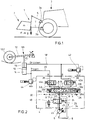
- FIG. 1 shows a first embodiment of a hoist according to the invention in a lateral schematic representation. It is designed as a front hitch 1 and attached to a front portion of a tractor 3 via three bearings, of which in Figure 1, only two bearings 3a, 3b are shown.
- the front lift 1 carries a symbolically illustrated attachment 2, for example, a mower.
- the front lift 1 has at least one upper link 5 and two lower links, of which in FIG. 1 only one lower link 7 is shown. At the front end portions of the lower link 7 is ever a crosspoint is arranged over which a weight F of the attachment to the tractor 3 is transmitted.
- a working cylinder of the front lifting mechanism 1 is in FIG. 1 not shown.
- FIG. 2 shows a hydraulic circuit diagram of a second embodiment of a hoist according to the invention 101 and a part of the hoist 101, from which a symbolically illustrated attachment 102 is supported.
- the control of the hoist 101 via a Hubwerksventilanordung 4, via the pressure chambers 14, 16 of a working cylinder 10 with a pump 6 or a tank 8 are connected.
- About the working cylinder 10 is an attachment 2 bearing on the tractor-hinged link assembly, from the in FIG. 2 only one lower link 12 is shown for lifting or lowering the attachment 2 pivoted.
- the working cylinder 10 has an effective in the direction "carrying" bottom space 14 and an effective in the direction "pressing" annulus 16, which are respectively connected via working lines 18, 20 with working ports A, B of the Hubtechniksventilan accent 4.
- Hubtechniksventilan are designed in disc design and in a (in FIG. 2 not shown) integrated mobile control block of the tractor.
- the Hubtechniksventilanordung 4 has a pressure port P and a tank port T, which are connected to the pump 6 and to the tank 8.
- the Hubtechniksventilan Aunt 4 is designed as a load-sensing system.
- an LS pressure compensator 24 is arranged in an inlet channel 22 connected to the connection P, which in the opening direction of the force of a spring and the load pressure of the working cylinder 10 in a load-sensing channel 25 and in the closing direction of the pressure downstream of the LS pressure compensator 24 is applied.
- the inlet channel 22 leads to the pressure port P of a continuously adjustable directional control valve 26 which is adjustable via a pilot valve arrangement 28a, 28b. This consists for example of a joystick controllable pressure reducing valves which are connected to the control oil supply 30.
- a valve spool of the directional control valve 28 is connected via a Zentrierfederan kann 32 a, 32 b in a (in FIG. 2 shown) in which the pressure port P and two working ports A, B and control ports XA, XB, X of the directional control valve 28 is shut off and a load-sensing connection LS is connected to a return port R of the directional control valve 28.
- the return port R is connected via a drain passage 34 to the tank port T of the Hubtechniksventilan accent 4.
- the valve spool of the directional control valve 26 can be moved from its basic position to the positions indicated by (a), in which a pressure medium connection from the input connection P to the working connection B is controlled via a metering orifice, so that corresponding pressure means in the Annulus 16 of the working cylinder 10 is promoted (function "pressing").
- the displaced thereby from the bottom space 14 pressure fluid flows via the connected to the return port R working port A to the tank 8 from.
- the two working ports A, B of the directional control valve 26 are connected via a feed channel 36 and a drain channel 38 to the working ports A, B of the Hubtechniksventilan Aunt 4.
- a lowering module 42a, 44a arranged, which serves in a spring-biased home position as a pilot check valve to leak oil-free clamping of the working cylinder 10 and controls in control positions flowing back from the working cylinder 10 pressure medium flow in the sense of a flow control.
- each lowering module 42a, 44a is acted upon in the direction of its return position by the pressure at the associated working port A, B of the directional valve 26 and in the direction of its opening / throttle positions by the control pressure of the control oil supply 30.
- a load pressure of the working cylinder 10 is tapped via the load sensing port LS of the directional control valve 26 and acts on the individual pressure compensator 24 - as already mentioned - in the opening direction.
- the directional control valve 26 is adjusted in the direction of its carrying positions (b), so that the pressure medium via the inlet channel 22, the individual pressure compensator 24, the controlled metering orifice of the directional control valve 26, the working port A of the directional control valve 26, the check valve of the Lowering module 44a, the flow channel 36 and the working line 20 is conveyed into the floor space 14.
- One Pump pressure is adjusted according to the load-sensing system so that it is always by a predetermined pressure difference above the highest load pressure of all consumers (the working cylinder 10 and other consumers not shown).
- the displaced during the extension of the working cylinder 10 from the annular space 16 pressure fluid flows through the working line 18, the drain passage 38, the controlled via the control pressure in the pilot oil supply 30 lowering module 42 a, the ports B, R of the directional control valve 26 and the drain passage 34 to the tank 8 ,
- the lowering module 42a acts as a discharge pressure compensator via which the outflowing pressure medium volume flow is regulated to a certain extent.
- second individual scale 24 may be fixed in its closed position in which an effective in the closing direction control surface via an electrically operated 2/2-way pilot valve 40 with the pressure upstream of the individual pressure compensator 24 is applied, which - as mentioned above - in each Case greater than the load pressure on the working cylinder 10, so that the individual pressure compensator 24 is kept closed.
- the pressure in the working line 18 can be limited by a continuously adjustable pressure-relief valve 42, so that the pressure in the annular space 16 is independent of the setting of the directional valve 26 and the pump pressure, for example in the range between 5 to 230 bar adjustable.
- the pressure-relief valve 42 to its minimum pressure, for example, 5 bar, the actually double-acting hoist 1 are operated single-acting, so that the attachment 2 also in setting the directional control valve 26 in its pressure positions (a) practically only falls due to its own weight. After lowering the directional control valve 26 can then in its floating position (c) be adjusted so that any unevenness of the soil can be compensated.
- a relief pressure relief valve 44 is provided in the working line 20, which is also designed to be continuously adjustable, and over which the pressure in the working line 20, for example, can be limited to values between 5 to 230 bar.
- the unloading pressure limiting valve 44 is designed with a falling characteristic and biased by a comparatively strong spring in the direction of maximum pressure. The setting of the pressure to be limited and thus the limiting lifting force of the working cylinder 10 via a proportionally adjustable electromagnet, which acts counter to the spring. This unloading pressure limiting valve 44 allows a relief pressure control, with reference to FIG. 7 will be described in more detail.
- the two pressure relief valves 42, 44 allow an inventive control of the working pressure of the two working lines 18, 20 and thus in the two pressure chambers 14, 16, be compensated in the differences in the efficiencies of the force exerted by the cylinder 10 on the lower link 12 force.
- the efficiency depends on an angle a, which consists between a piston rod of the working cylinder 10 and the lower link 12.
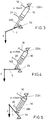
- FIGS. 3 to 5 each show a section of a third embodiment of a hoist according to the invention in three different lifting heights.
- the hoist has the articulated to the bearing 3b of the tractor lower link 7 FIG. 1 ,
- the third embodiment further has the power cylinder 10 according to FIG. 2 which is rotatably coupled to a bearing 203c of the tractor.
- a piston rod 209 of the working cylinder 10 is coupled from above to the lower link 7.
- the third embodiment further has a hydraulic supply according to FIG. 2 with the working line 18 for "pressing" and with the working line 20 for relieving or "carrying".
- the working cylinder 10 with the piston rod 209 is employed obliquely to the floor (not shown) at all lifting heights shown.
- the lower link 7 is at an in FIG. 4 middle height shown approximately horizontally to the ground, while at low Lifting heights according to FIG. 3 and at high lifting heights according to FIG. 5 is made obliquely to the ground.
- the lower link 7 pivots about the bearing 3b over a comparatively large angular range
- the working cylinder 10 pivots about the bearing 203c over a comparatively small angular range.
- this operating principle between the piston rod 209 and the lower link 7 theoretically angle of attack a in a range of 0 to 180 ° can result, wherein this angular range is kept significantly smaller in practice.
- FIG. 3 In the three exemplary lift heights of the third embodiment is in FIG. 3 an angle of attack of a ⁇ 34 °, in FIG. 4 an angle of attack of a ⁇ 57 ° and in FIG. 5 an angle of attack of a ⁇ 106 ° is shown.
- a cylinder-force dependent on the pitch a cylinder force must be applied via the cylinder 10. This is minimal when the angle of attack is a ⁇ 90 ° and increases disproportionately when the angle of attack a decreases in the direction of 0 ° or increases in the direction of 180 °.
- the cylinder force to be applied by the cylinder 10 is quite close to a minimum, while at the in FIG. 4 Lifting height significantly increased and at the in FIG. 3 shown lifting height is significantly increased again.
- the pressure p in the working line 18 and / or in the working line 20 is controlled in dependence on the angle of attack a that depending on the use of the hoist a constant unloading force or this opposing pressure force is generated. These forces act in a direction perpendicular to the ground or in the effective direction of the hoist.
- This scheme according to the invention is for example advantageous if the attachment is ground profile controlled. This can be, for example, a mower, which should not load with its full weight F on the ground, but should always be relieved by a certain unloading force from the hoist according to the invention.
- a modified cylinder force is necessary to maintain the predetermined unloading force. This is achieved by appropriate pressure adjustment in the working lines 18 and 20.
- the regulation according to the invention of the pressures in the working lines 18 and 20 can take place via the respective associated pressure limiting valve 42, 44 (cf. FIG. 2 ).
- FIG. 6 shows a diagram with a characteristic 211 for controlling a fourth embodiment of a hoist according to the invention.
- the lifting height of the lifting mechanism is plotted on the x-axis in a range of 0 to 100%, while on the y-axis, the pressure p is plotted in one of the pressure chambers of the working cylinder.
- the change of pressure shown leads - as related to the FIGS. 3 to 5 explains - to a change in the cylinder force, so that the predetermined unloading force or pressing force remains constant.
- a minimum lifting height is given, in which the angle of attack a between the working cylinder and the lower link is maximum, so that a comparatively low pressure p in the pressure chamber for generating the predetermined unloading force or pressing force is necessary.
- the hoisting gear has reached its maximum lifting height, the angle of attack a having changed (reduced or increased) in such a way that the pressure and thus the cylinder force along the characteristic curve 211 had to be increased in order to provide the constant unloading force or pressing force.
- FIG. 7 is a part of a control panel of the tractor shown, via which the two pressure relief valves 42, 44 of the double-acting hoist 101 (see. FIG. 2 ) for adjusting a maximum pressure in the working lines 18, 20 and thus for adjusting the maximum force of the hoist 101 can be adjusted.
- the control panel 46 has a switch 48, via which the pressure control can be switched on.
- the pressure-relief valve 42 is set at maximum pressure, so that the tractor, as in the upper left in FIG. 7 represented by lowering the hoist 101 can be excavated.
- a potentiometer 50 is further provided, via which by turning (in FIG. 7 ) to the left via the pressure-limiting valve 42 limited pressure or by turning (in FIG. 7 ) to the right on the relief pressure relief valve 44 limited pressure is adjustable.
- the relief pressure control by turning the potentiometer 50 (in FIG. 7 ) are activated to the right, wherein the relief pressure increases with increasing adjustment of the potentiometer 50 from the basic position.
- the hoist 101 In the neutral position (0) of the potentiometer 50, the hoist 101 is operated single-acting, i. the pressure in the working line 18 is limited to the minimum value. In this case, the relief pressure relief valve 44 is always set to the maximum pressure, so that the attachment can be safely carried.
- the control of the hoist 101 is carried out in the usual manner after a position and / or draft control.
- This maximum relief pressure is also preset by the control unit of the hoist control in the event of a stop of the electrohydraulic hoist control, in the event of locking of the electrohydraulic hoist control, for example in the event of a tractor start, in the event of a fault, etc., and in the transport position, which is set via a mode switch.
- a hoist for a mobile machine with a working cylinder through which a force with different degrees of efficiency to the hoist is transferable.
- a working pressure of the working cylinder can be regulated as a function of the efficiency.
Landscapes
- Life Sciences & Earth Sciences (AREA)
- Engineering & Computer Science (AREA)
- Mechanical Engineering (AREA)
- Soil Sciences (AREA)
- Environmental Sciences (AREA)
- Lifting Devices For Agricultural Implements (AREA)
Description
- Die Erfindung betrifft ein Hubwerk gemäß dem Oberbegriff des Patentanspruchs 1 und ein Verfahren zum Betrieb eines Hubwerks.
- In der Druckschrift
DE 10 2007 040 877 A1 ist ein Hubwerk offenbart, das einen doppelt wirkenden Zylinder hat, über den wahlweise eine Hebe- bzw. Entlastungskraft oder eine Andrückkraft auf das Hubwerk und damit auf ein damit verbundenes Anbaugerät übertragen werden kann. Dabei ist zur Versorgung des Zylinders eine hydraulische Schaltung mit Entlastungsdruckregelung vorgesehen. - Nachteilig an derartigen Hubwerken ist, dass die an das Anbaugerät übertragene Hebe- bzw. Entlastungskraft und die Andrückkraft von der Hubhöhe des Hubwerks abhängen. Das liegt insbesondere daran, dass der Zylinder seine Kraft mit unterschiedlichen Wirkungsgraden an das Hubwerk (insbesondere an einen Unterlenker) überträgt. Dieser Effekt entsteht durch unterschiedliche Winkel zwischen dem Zylinder und dem Unterlenker in Abhängigkeit von der Hubhöhe des Hubwerkes.
- Dem gegenüber liegt der Erfindung die Aufgabe zu Grunde, ein Hubwerk zu schaffen, dessen Hebe- bzw. Entlastungskraft oder dessen Andrückkraft unabhängig von der Hubhöhe geregelt sind.
- Diese Aufgabe wird gelöst durch ein Hubwerk mit den Merkmalen des Patentanspruchs 1 und durch ein Verfahren zum Betreiben eines Hubwerks mit den Merkmalen des Patentanspruchs 5.
- Das erfindungsgemäße Hubwerk für eine mobile Arbeitsmaschine, z.B. für einen Traktor, hat einen Arbeitszylinder, über den eine Zylinderkraft mit unterschiedlichen Wirkungsgraden an das Hubwerk übertragbar ist. Die Zylinderkraft wirkt insbesondere auch über einen Kolben und über eine Kolbenstange des Arbeitszylinders. Dabei ist ein Arbeitsdruck des Arbeitszylinders in Abhängigkeit des Wirkungsgrades regelbar. Damit kann die Hebe- bzw. Entlastungskraft oder die Andrückkraft (je nach Wirkrichtung des Arbeitszylinders) unabhängig von der Hubhöhe geregelt und dabei konstant gehalten werden.
- Weitere vorteilhafte Ausgestaltungen der Erfindung sind in den abhängigen Patentansprüchen beschrieben.
- Bei einer bevorzugten Weiterbildung bzw. bei einem bevorzugten Anwendungsfall der Erfindung entstehen die unterschiedlichen Wirkungsgrade durch unterschiedliche Anstellwinkel zwischen dem Arbeitszylinder und einer Koppelstange bzw. einem Lenker, insbesondere Unterlenker. Somit hängen die unterschiedlichen Wirkungsgrade von unterschiedlichen Anstellwinkeln des Arbeitszylinders gegenüber der Koppelstange bzw. dem Lenker ab.
- Bei einer bevorzugten Weiterbildung hat das Hubwerk ein proportionales Druckbegrenzungsventil, das an einer an den Arbeitszylinder angeschlossenen Arbeitsleitung angeordnet ist. Damit kann der Druck geregelt werden.
- Bei einer bevorzugten Weiterbildung hat der Arbeitzylinder zwei Druckräume und ist doppelt wirkend, wobei jeder Druckraum mit dem Arbeitsdruck beaufschlagbar ist. Damit lassen sich Hebe- bzw. Entlastungskräfte und Andrückkräfte mit dem selben erfindungsgemäßen Hubwerk erzeugen, die beide unabhängig von der Hubhöhe geregelt werden können.
- Bei dem erfindungsgemäßen Verfahren zum Betrieb eines Hubwerks, z.B. eines Fronthubwerks, einer mobilen Arbeitsmaschine, z.B. eines Traktors, wird ein Arbeitsdruck eines Arbeitszylinders in Abhängigkeit eines Wirkungsgrades einer durch den Arbeitsdruck erzeugten und vom Arbeitszylinder an das Hubwerk übertragenen Zylinderkraft geregelt. Damit können die Hebe- bzw. Entlastungskraft oder die Andrückkraft (je nach Wirkrichtung des Arbeitszylinders) unabhängig von der Hubhöhe geregelt werden.
- Bei einer bevorzugten Weiterbildung des erfindungsgemäßen Verfahrens wird der Arbeitsdruck derart geregelt, dass Unterschiede des Wirkungsgrades kompensiert werden. Damit können die Hebe- bzw. Entlastungskraft oder die Andrückkraft (je nach Wirkrichtung des Arbeitszylinders) unabhängig von der Hubhöhe konstant gehalten werden.
- Bei einer bevorzugten Weiterbildung bzw. bei einem bevorzugten Anwendungsfall hängt der Wirkungsgrad von einem Angriffswinkel der Zylinderkraft ab oder der Wirkungsgrad wird sogar vom Angriffswinkel bestimmt. Der Arbeitsdruck wird also in Abhängigkeit dieses Angriffswinkels geregelt.
- Es wird besonders bevorzugt, wenn der Arbeitsdruck bei einem Angriffswinkel von 90 Grad auf einen geringeren Wert geregelt wird, als bei einem Angriffswinkel größer oder kleiner als 90 Grad.
- Bei einer bevorzugten Weiterbildung bzw. bei einem bevorzugten Anwendungsfall ergibt sich der Angriffswinkel zwischen dem Arbeitszylinder und einer Koppelstange oder einem Lenker - insbesondere Unterlenker - des Hubwerks.
- Bei einer vorteilhaften Ausführungsform ist ein erster Endabschnitt der Koppelstange bzw. des Lenkers an der mobilen Arbeitsmaschine angelenkt, während ein zweiter Endabschnitt über einen Koppelpunkt mit einem Anbaugerät verbunden ist.
- Bei einer bevorzugten Weiterbildung bzw. bei einem bevorzugten Anwendungsfall der Erfindung wird das Anbaugerät abhängig von einem Bodenprofil betrieben, bei denen Bodenunebenheiten über das Hubwerk "gefolgt" werden muss. Beispiele für derartige Anbaugeräte sind Mähwerke, Schneepflüge und Packerwalzen, Dabei wird an das Anbaugerät über den Koppelpunkt eine im Wesentlichen konstante Hebe- bzw. Entlastungskraft oder Andrückkraft übertragen.
- Der Arbeitsdruck kann über ein proportionales Druckbegrenzungsventil eingestellt werden, das an einer an den Arbeitszylinder angeschlossenen Arbeitsleitung angeordnet ist.
- Im Folgenden werden anhand der Figuren verschiedene Ausführungsbeispiele der Erfindung detailliert beschrieben. Es zeigen:
-
Figur 1 ein erstes Ausführungsbeispiel eines erfindungsgemäßen Hubwerks in einer seitlichen schematischen Darstellung; -
Figur 2 einen Hydraulikschaltplan eines zweiten Ausführungsbeispiels eines erfindungsgemäßen Hubwerks; -
Figuren 3 bis 5 einen Ausschnitt eines dritten Ausführungsbeispiels eines erfindungsgemäßen Hubwerks in drei verschiedenen Hubhöhen; -
Figur 6 ein Diagramm, das den Zusammenhang zwischen Hubhöhe und Arbeitsdruck eines vierten Ausführungsbeispiels eines erfindungsgemäßen Hubwerks zeigt; und -
Figur 7 eine Prinzipdarstellung eines Bedienfelds eines erfindungsgemäßen Hubwerks. -
Figur 1 zeigt ein erstes Ausführungsbeispiel eines erfindungsgemäßen Hubwerks in einer seitlichen schematischen Darstellung. Es ist als Fronthubwerk 1 ausgeführt und an einem vorderen Bereich eines Traktors 3 über drei Lager befestigt, von denen in Figur 1 nur zwei Lager 3a, 3b gezeigt sind. Das Fronthubwerk 1 trägt ein symbolisch dargestelltes Anbaugerät 2, beispielsweise ein Mähwerk. Das Fronthubwerk 1 hat zumindest einen Oberlenker 5 und zwei Unterlenker, von denen inFigur 1 nur ein Unterlenker 7 dargestellt ist. An den vorderen Endabschnitten der Unterlenker 7 ist je ein Koppelpunkt angeordnet über den eine Gewichtskraft F des Anbaugerätes an den Traktor 3 übertragen wird. Ein Arbeitszylinder des Fronthubwerks 1 ist inFigur 1 nicht dargestellt. -
Figur 2 zeigt einen Hydraulikschaltplan eines zweiten Ausführungsbeispiels eines erfindungsgemäßen Hubwerks 101 und einen Teil des Hubwerks 101, von dem ein symbolisch dargestelltes Anbaugerät 102 getragen wird. Die Ansteuerung des Hubwerks 101 erfolgt über eine Hubwerksventilanordung 4, über die Druckräume 14, 16 eines Arbeitszylinders 10 mit einer Pumpe 6 oder einem Tank 8 verbindbar sind. Über den Arbeitszylinder 10 ist eine das Anbaugerät 2 tragende am Traktor angelenkte Lenkeranordnung, von der inFigur 2 nur ein Unterlenker 12 gezeigt ist, zum Anheben oder Absenken des Anbaugerätes 2 verschwenkbar. Der Arbeitszylinder 10 hat einen in Richtung "Tragen" wirksamen Bodenraum 14 und einen in Richtung "Drücken" wirksamen Ringraum 16, die jeweils über Arbeitsleitungen 18, 20 mit Arbeitsanschlüssen A, B der Hubwerksventilanordnung 4 verbunden sind. - Üblicherweise sind diese Hubwerksventilanordnungen in Scheibenbauweise ausgeführt und in einem (in
Figur 2 nicht gezeigten) Mobilsteuerblock des Traktors integriert. - Die Hubwerksventilanordung 4 hat einen Druckanschluss P und einen Tankanschluss T, die mit der Pumpe 6 bzw. mit dem Tank 8 verbunden sind.
- Die Hubwerksventilanordnung 4 ist als Load-Sensing-System ausgeführt. Dazu ist in einem an den Anschluss P angeschlossenen Zulaufkanal 22 eine LS-Druckwaage 24 angeordnet, die in Öffnungsrichtung von der Kraft einer Feder und dem Lastdruck des Arbeitszylinders 10 in einem Load-Sensing-Kanal 25 und in Schließrichtung vom Druck stromabwärts der LS-Druckwaage 24 beaufschlagt ist. Der Zulaufkanal 22 führt zum Druckanschluss P eines stetig verstellbaren Wegeventils 26, das über eine Pilotventilanordnung 28a, 28b verstellbar ist. Diese besteht beispielsweise aus über einen Joystick ansteuerbaren Druckreduzierventilen, die an die Steuerölversorgung 30 angeschlossen sind. Ein Ventilschieber des Wegeventils 28 ist über eine Zentrierfederanordnung 32a, 32b in eine (in
Figur 2 gezeigte) Grundposition vorgespannt, in der der Druckanschluss P sowie zwei Arbeitsanschlüsse A, B und Steueranschlüsse XA, XB, X des Wegeventils 28 abgesperrt sowie ein Load-Sensing-Anschluss LS mit einem Rücklaufanschluss R des Wegeventils 28 verbunden ist. Der Rücklaufanschluss R ist über einen Ablaufkanal 34 mit dem Tankanschluss T der Hubwerksventilanordnung 4 verbunden. - Durch geeignete Einstellung der Pilotventilanordnung 28a, 28b kann der Ventilschieber des Wegeventils 26 aus seiner Grundposition in die mit (a) gekennzeichneten Positionen verstellt werden, in denen über eine Zumessblende eine Druckmittelverbindung vom Eingangsanschluss P zum Arbeitsanschluss B aufgesteuert wird, so dass entsprechend Druckmittel in den Ringraum 16 des Arbeitszylinders 10 gefördert wird (Funktion "Drücken"). Das dabei aus dem Bodenraum 14 verdrängte Druckmittel strömt über den mit dem Rücklaufanschluss R verbundenen Arbeitsanschluss A zum Tank 8 ab. Beim Verstellen in die mit (b) gekennzeichneten Positionen wird über die Zumessblende eine Druckmittelverbindung vom Druckanschluss P zum Arbeitsanschluss A und der Arbeitsanschluss B des Wegeventils 26 mit dem Rücklaufanschluss R verbunden, so dass zum Entlasten oder zum Anheben des Anbaugerätes Druckmittel in den Bodenraum 14 gefördert wird und das aus dem Ringraum 16 verdrängte Druckmittel zum Tank 8 abströmt (Funktion "Tragen").
- Beim Verschieben des Ventilschiebers des Wegeventils 26 in seine mit (c) gekennzeichnete Schwimmstellung sind die beiden Arbeitsanschlüsse A, B des Wegeventils 26 und damit auch die beiden Druckräume 14, 16 des Arbeitszylinders 10 mit dem Rücklaufanschluss R verbunden, so dass das Anbaugerät 2 lastfrei auf dem Boden aufliegt.
- Die beiden Arbeitsanschlüsse A, B des Wegeventils 26 sind über einen Vorlaufkanal 36 bzw. einen Ablaufkanal 38 mit den Arbeitsanschlüssen A, B der Hubwerksventilanordnung 4 verbunden. In den Kanälen 36, 38 ist jeweils ein Senkenmodul 42a, 44a angeordnet, das in einer federvorgespannten Grundposition als entsperrbares Rückschlagventil zu leckölfreien Einspannung des Arbeitszylinders 10 dient und in Regelpositionen den vom Arbeitszylinder 10 zurückströmenden Druckmittelvolumenstrom im Sinne einer Ablaufregelung steuert. Hierzu ist jedes Senkenmodul 42a, 44a in Richtung seiner Rückschlagposition vom Druck an dem zugeordneten Arbeitsanschluss A, B des Wegeventils 26 und in Richtung seiner Öffnungs-/Drosselpositionen durch den Steuerdruck der Steuerölversorgung 30 beaufschlagt.
- Ein Lastdruck des Arbeitszylinders 10 wird über den Load-Sensing-Anschluss LS des Wegeventils 26 abgegriffen und beaufschlagt die Individualdruckwaage 24 - wie bereits erwähnt - in Öffnungsrichtung.
- Zum Ausfahren des Arbeitszylinders 10 wird das Wegeventil 26 in Richtung seiner Tragen-Positionen (b) verstellt, so dass das Druckmittel über den Zulaufkanal 22, die Individualdruckwaage 24, die aufgesteuerte Zumessblende des Wegeventils 26, den Arbeitsanschluss A des Wegeventils 26, das Rückschlagventil des Senkenmoduls 44a, den Vorlaufkanal 36 und die Arbeitsleitung 20 in den Bodenraum 14 gefördert wird. Ein Pumpendruck ist gemäß dem Load-Sensing-System dabei so eingestellt, dass er stets um eine vorbestimmte Druckdifferenz oberhalb des höchsten Lastdrucks aller Verbraucher (des Arbeitszylinders 10 und weiterer nicht gezeigter Verbraucher) liegt. Das beim Ausfahren des Arbeitszylinders 10 aus dem Ringraum 16 verdrängte Druckmittel strömt über die Arbeitsleitung 18, den Ablaufkanal 38, das über den Steuerdruck in der Steuerölversorgung 30 aufgesteuerte Senkenmodul 42a, die Anschlüsse B, R des Wegeventils 26 und den Ablaufkanal 34 zum Tank 8 ab. Das Senkenmodul 42a wirkt dabei als Ablaufdruckwaage, über die der ablaufende Druckmittelvolumenstrom in gewissem Umfang geregelt wird.
- Das Einfahren des Arbeitszylinders 10 und damit das Absenken des Anbaugerätes 2 aus einer oberen Hubwerkslage und ggf. ein Andrücken des Anbaugerätes 2 erfolgt entsprechend durch Verstellen des Wegeventils 26 in Richtung seiner mit (a) gekennzeichneten Drücken-Positionen.
- Bei dem in
Figur 2 dargestellten zweiten Ausführungsbeispiel kann die Individualdruckwaage 24 in ihrer Schließposition fixiert werden, in dem eine in Schließrichtung wirksame Steuerfläche über ein elektrisch betätigtes 2/2-Wege-Pilotventil 40 mit dem Druck stromaufwärts der Individualdruckwaage 24 beaufschlagt wird, der - wie oben erwähnt - in jedem Fall größer als der Lastdruck am Arbeitszylinder 10 ist, so dass die Individualdruckwaage 24 geschlossen gehalten wird. Durch diese Maßnahme ist es möglich, trotz aufgesteuerter Zumessblende den Druckmittelströmungspfad zwischen Pumpe 6 und Wegeventil 26 abzusperren. - Der Druck in der Arbeitsleitung 18 kann über ein stetig verstellbares Drücken-Druckbegrenzungsventil 42 begrenzt werden, so dass der Druck im Ringraum 16 unabhängig von der Einstellung des Wegeventils 26 und von dem Pumpendruck, beispielsweise im Bereich zwischen 5 bis 230 bar einstellbar ist. Auf diese Weise kann beispielsweise durch Verstellen des Drücken-Druckbegrenzungsventils 42 auf seinen Minimaldruck, beispielsweise 5 bar, das eigentlich doppelt wirkende Hubwerk 1 einfach wirkend betrieben werden, so dass das Anbaugerät 2 auch bei Einstellung des Wegeventils 26 in seine Drücken-Positionen (a) praktisch nur auf Grund seines Eigengewichtes absinkt. Nach dem Absenken kann das Wegeventil 26 dann in seine Schwimmstellung (c) verstellt werden, so dass eventuelle Unebenheiten des Bodens ausgeglichen werden können.
- Außerdem ist in der Arbeitsleitung 20 ein Entlasten-Druckbegrenzungsventil 44 vorgesehen, das ebenfalls stetig verstellbar ausgeführt ist, und über das der Druck in der Arbeitsleitung 20 beispielsweise auf Werte zwischen 5 bis 230 bar begrenzt werden kann. Das Entlasten-Druckbegrenzungsventil 44 ist mit einer abfallenden Kennlinie ausgeführt und über eine vergleichsweise starke Feder in Richtung des maximalen Drucks vorgespannt. Die Einstellung des zu begrenzenden Drucks und damit der zu begrenzenden Hebekraft des Arbeitszylinders 10 erfolgt über einen proportional verstellbaren Elektromagneten, der entgegen der Feder wirkt. Dieses Entlasten-Druckbegrenzungsventil 44 ermöglicht eine Entlastungsdruckregelung, die mit Bezug zu
Figur 7 näher beschrieben wird. - Weiterhin ermöglichen die beiden Druckbegrenzungsventile 42, 44 eine erfindungsgemäße Regelung des Arbeitsdrucks der beiden Arbeitsleitungen 18, 20 und damit in den beiden Druckräumen 14, 16, bei der Unterschiede in den Wirkungsgraden der von dem Arbeitszylinder 10 auf den Unterlenker 12 ausgeübten Kraft kompensiert werden. Der Wirkungsgrad hängt von einem Winkel a ab, der zwischen einer Kolbenstange des Arbeitszylinders 10 und dem Unterlenker 12 besteht.
- Die
Figuren 3 bis 5 zeigen jeweils einen Ausschnitt eines dritten Ausführungsbeispiels eines erfindungsgemäßen Hubwerks in drei verschiedenen Hubhöhen. Das Hubwerk hat den an das Lager 3b des Traktors angelenkten Unterlenker 7 gemäßFigur 1 . Das dritte Ausführungsbeispiel hat weiterhin den Arbeitszylinder 10 gemäßFigur 2 , der an ein Lager 203c des Traktors drehbar gekoppelt ist. Eine Kolbenstange 209 des Arbeitszylinders 10 ist von oben an den Unterlenker 7 angekoppelt. Das dritte Ausführungsbeispiel hat weiterhin eine hydraulische Versorgung gemäßFigur 2 mit der Arbeitsleitung 18 zum "Drücken" und mit der Arbeitsleitung 20 zum Entlasten bzw. "Tragen". - Der Arbeitszylinder 10 mit der Kolbenstange 209 ist bei allen gezeigten Hubhöhen schräg zum (nicht gezeigten) Boden angestellt. Der Unterlenker 7 ist bei einer in
Figur 4 gezeigten mittleren Hubhöhe etwa waagerecht zum Boden, während er bei niedrigen Hubhöhen gemäßFigur 3 und bei hohen Hubhöhen gemäßFigur 5 schräg zum Boden angestellt ist. Dabei schwenkt der Unterlenker 7 über einen vergleichsweise großen Winkelbereich um das Lager 3b, während der Arbeitszylinder 10 über einen vergleichsweise kleinen Winkelbereich um das Lager 203c schwenkt. Bei diesem Funktionsprinzip können sich zwischen der Kolbenstange 209 und dem Unterlenker 7 theoretisch Anstellwinkel a in einem Bereich von 0 bis 180° ergeben, wobei dieser Winkelbereich in der Praxis deutlich kleiner gehalten wird. In den drei beispielhaften Hubhöhen des dritten Ausführungsbeispiels ist inFigur 3 ein Anstellwinkel von a ∼ 34°, inFigur 4 ein Anstellwinkel von a ∼ 57° und inFigur 5 ein Anstellwinkel von a ∼ 106° gezeigt. - Bei einer vorbestimmten Gewichtskraft F des in den
Figuren 3 bis 5 nicht gezeigten Anbaugerätes oder um eine vorbestimmte von der Hubhöhe unabhängige Entlastungskraft auf das Anbaugerät auszuüben, muss über den Zylinder 10 eine vom Anstellwinkel a abhängige Zylinderkraft aufgebracht werden. Diese ist minimal, wenn der Anstellwinkel a ∼ 90° beträgt und erhöht sich überproportional, wenn sich der Anstellwinkel a in Richtung 0° verringert oder in Richtung 180° vergrößert. Bei der inFigur 5 gezeigten Hubhöhe ist somit die vom Zylinder 10 aufzubringende Zylinderkraft recht nah an einem Minimum, während sie bei der inFigur 4 gezeigten Hubhöhe deutlich erhöht und bei der inFigur 3 gezeigten Hubhöhe nochmals deutlich erhöht ist. - Bei dem erfindungsgemäßen Hubwerk wird der Druck p in der Arbeitsleitung 18 und/oder in der Arbeitsleitung 20 derart in Abhängigkeit vom Anstellwinkel a geregelt, dass je nach Einsatz des Hubwerks eine konstante Entlastungskraft oder dieser entgegen gerichtete Andrückkraft erzeugt wird. Diese Kräfte wirken in einer Richtung senkrecht zum Boden bzw. in Wirkrichtung des Hubwerks. Diese erfindungsgemäße Regelung ist z.B. dann von Vorteil, wenn das Anbaugerät bodenprofilgesteuert ist. Dies kann z.B. ein Mähwerk sein, das nicht mit seiner vollen Gewichtskraft F auf dem Boden lasten soll, sondern stets um eine gewisse Entlastungskraft vom erfindungsgemäßen Hubwerk entlastet werden soll. Wenn sich auf Grund von Unebenheiten des Bodens die Hubhöhe des erfindungsgemäßen Hubwerks anpassen muss, ist zur Aufrechterhaltung der vorbestimmten Entlastungskraft eine veränderte Zylinderkraft nötig. Diese wird durch entsprechende Druckanpassung in den Arbeitsleitungen 18 und 20 erreicht. Die erfindungsgemäße Regelung der Drücke in den Arbeitsleitungen 18 und 20 kann über das jeweils zugeordnete Druckbegrenzungsventil 42, 44 erfolgen (vgl.
Figur 2 ). -
Figur 6 zeigt ein Diagramm mit einer Kennlinie 211 zur Regelung eines vierten Ausführungsbeispiels eines erfindungsgemäßen Hubwerks. Dabei ist auf der x-Achse die Hubhöhe des Hubwerks in einem Bereich von 0 bis 100 % aufgetragen, während auf der y-Achse der Druck p in einem der Druckräume des Arbeitszylinders aufgetragen ist. Die gezeigte Änderung des Drucks führt - wie mit Bezug zu denFiguren 3 bis 5 erläutert - zu einer Veränderung der Zylinderkraft, so dass die vorbestimmte Entlastungskraft oder Andrückkraft konstant bleibt. - Bei einem mit dem Bezugszeichen 211a markierten Betriebszustand ist eine minimale Hubhöhe gegeben, bei der der Anstellwinkel a zwischen dem Arbeitszylinder und dem Unterlenker maximal ist, so dass ein vergleichsweise geringer Druck p im Druckraum zur Erzeugung der vorbestimmten Entlastungskraft oder Andrückkraft nötig ist.
- Im Betriebszustand 211b hat das Hubwerk seine maximale Hubhöhe erreicht, wobei der Anstellwinkel a sich derart verändert (verringert oder vergrößert) hat, dass zur Bereitstellung der konstanten Entlastungskraft oder Andrückkraft der Druck und damit die Zylinderkraft entlang der Kennlinie 211 erhöht werden mussten.
- In
Figur 7 ist ein Teil eines Bedienfeldes des Traktors dargestellt, über das die beiden Druckbegrenzungsventile 42, 44 des doppelt wirkenden Hubwerks 101 (vgl.Figur 2 ) zum Einstellen eines Maximaldrucks in den Arbeitsleitungen 18, 20 und somit zum Einstellen der maximalen Kraft des Hubwerks 101 verstellt werden kann. Das Bedienfeld 46 hat einen Schalter 48, über den die Druckregelung einschaltbar ist. Dazu wird der Schalter 48 in die inFigur 7 gezeigte untere Stellung geschaltet. Bei Verstellen des Schalters 48 nach oben wird das Drücken-Druckbegrenzungsventil 42 auf Maximaldruck eingestellt, so dass der Traktor, wie oben links inFigur 7 dargestellt, durch Absenken des Hubwerks 101 ausgehoben werden kann. - Am Bedienfeld 46 ist des Weiteren ein Potenziometer 50 vorgesehen, über das durch Drehen (in
Figur 7 ) nach links der über das Drücken-Druckbegrenzungsventil 42 begrenzte Druck oder durch Drehen (inFigur 7 ) nach rechts der über das Entlasten-Druckbegrenzungsventil 44 begrenzte Druck einstellbar ist. Demzufolge kann die Entlastungsdruckregelung durch Verdrehen des Potenziometers 50 (inFigur 7 ) nach rechts aktiviert werden, wobei der Entlastungsdruck mit zunehmender Verstellung des Potenziometers 50 aus der Grundposition ansteigt. - In der Neutralstellung (0) des Potenziometers 50 wird das Hubwerk 101 einfach wirkend betrieben, d.h. der Druck in der Arbeitsleitung 18 wird auf den Minimalwert begrenzt. Dabei wird das Entlasten-Druckbegrenzungsventil 44 stets auf den maximalen Druck eingestellt, damit das Anbaugerät sicher getragen werden kann. Die Ansteuerung des Hubwerks 101 erfolgt in üblicher Weise nach einer Lage- und/oder Zugkraftregelung. Dieser maximale Entlastungsdruck wird auch bei einem Stopp der elektrohydraulischen Hubwerksregelung, bei einer Verriegelung der elektrohydraulischen Hubwerksregelung, beispielsweise bei einem Traktorstart, im Fehlerfall usw. und in der Transportstellung, die über einen Modusschalter eingestellt ist vom Steuergerät der Hubwerksregelung voreingestellt.
- Offenbart ist ein Hubwerk für eine mobile Arbeitsmaschine mit einem Arbeitszylinder, über den eine Kraft mit unterschiedlichen Wirkungsgraden an das Hubwerk übertragbar ist. Dabei ist ein Arbeitsdruck des Arbeitszylinders in Abhängigkeit des Wirkungsgrades regelbar.
- Offenbart ist weiterhin ein entsprechendes Verfahren zum Betrieb eines Hubwerks einer mobilen Arbeitsmaschine, wobei ein Arbeitsdruck eines Arbeitszylinders in Abhängigkeit eines Wirkungsgrades einer durch den Arbeitsdruck erzeugten vom Arbeitszylinder an das Hubwerk übertragenen Kraft geregelt wird.
Claims (12)
- Hubwerk für eine mobile Arbeitsmaschine (3) mit einem Arbeitszylinder (10), über den eine Zylinderkraft mit unterschiedlichen Wirkungsgraden an das Hubwerk übertragbar ist, dadurch gekennzeichnet, dass ein Arbeitsdruck des Arbeitszylinders (10) in Abhängigkeit des Wirkungsgrades regelbar ist.
- Hubwerk nach Anspruch 1, wobei die unterschiedlichen Wirkungsgrade von unterschiedlichen Anstellwinkeln (a) zwischen dem Arbeitszylinder (10) und einem Lenker (7) abhängig sind.
- Hubwerk nach Anspruch 1 mit einem proportionalen Druckbegrenzungsventil (42, 44), das an einer an den Arbeitszylinder (10) angeschlossenen Arbeitsleitung (18, 20) angeordnet ist.
- Hubwerk nach Anspruch 1, wobei der Arbeitzylinder (10) zwei Druckräume (14, 16) hat, wobei jeder Druckraum (14, 16) mit dem Arbeitsdruck beaufschlagbar ist.
- Verfahren zum Betrieb eines Hubwerks einer mobilen Arbeitsmaschine, wobei ein Arbeitsdruck eines Arbeitszylinders (10) in Abhängigkeit eines Wirkungsgrades einer durch den Arbeitsdruck erzeugten vom Arbeitszylinder an das Hubwerk übertragenen Zylinderkraft geregelt wird.
- Verfahren nach Anspruch 5, wobei der Arbeitsdruck derart geregelt wird, dass Unterschiede des Wirkungsgrades kompensiert werden.
- Verfahren nach Anspruch 5, wobei der Wirkungsgrad von einem Angriffswinkel der Zylinderkraft abhängt.
- Verfahren nach Anspruch 7, wobei der Arbeitsdruck bei einem Angriffswinkel von 90 Grad geringer ist, als bei einem Angriffswinkel größer oder kleiner als 90 Grad.
- Verfahren nach Anspruch 7, wobei der Angriffswinkel gleich einem Anstellwinkel (a) zwischen dem Arbeitszylinder (10) und einem Lenker (7) ist.
- Verfahren nach Anspruch 9, wobei ein erster Endabschnitt des Lenkers (7) an der mobilen Arbeitsmaschine (3) angelenkt ist, während ein zweiter Endabschnitt über einen Koppelpunkt mit einem Anbaugerät (2; 102) verbunden ist.
- Verfahren nach Anspruch 10, wobei das Anbaugerät (2; 102) abhängig von einem Bodenprofil betrieben wird, und wobei an das Anbaugerät (2; 102) eine im Wesentlichen konstante Entlastungskraft oder Andrückkraft übertragen wird.
- Verfahren nach Anspruch 5, wobei der Arbeitsdruck über ein proportionales Druckbegrenzungsventil (42, 44) eingestellt wird, das an einer an den Arbeitszylinder (10) angeschlossenen Arbeitsleitung (18, 20) angeordnet ist.
Applications Claiming Priority (1)
| Application Number | Priority Date | Filing Date | Title |
|---|---|---|---|
| DE201010026453 DE102010026453A1 (de) | 2010-07-08 | 2010-07-08 | Hubwerk |
Publications (2)
| Publication Number | Publication Date |
|---|---|
| EP2404493A1 EP2404493A1 (de) | 2012-01-11 |
| EP2404493B1 true EP2404493B1 (de) | 2017-12-06 |
Family
ID=44780171
Family Applications (1)
| Application Number | Title | Priority Date | Filing Date |
|---|---|---|---|
| EP11004863.4A Active EP2404493B1 (de) | 2010-07-08 | 2011-06-15 | Hubwerk |
Country Status (2)
| Country | Link |
|---|---|
| EP (1) | EP2404493B1 (de) |
| DE (1) | DE102010026453A1 (de) |
Cited By (1)
| Publication number | Priority date | Publication date | Assignee | Title |
|---|---|---|---|---|
| DE102017219942A1 (de) | 2017-11-09 | 2019-05-09 | Robert Bosch Gmbh | Ventilanordung für Hubwerkssteuerung mit einer Druckregelvorrichtung |
Families Citing this family (4)
| Publication number | Priority date | Publication date | Assignee | Title |
|---|---|---|---|---|
| DE102012017672A1 (de) * | 2012-09-07 | 2014-05-15 | Hydac Filtertechnik Gmbh | Ventilvorrichtung |
| DE102013207934A1 (de) * | 2013-04-30 | 2014-10-30 | Bayerische Motoren Werke Aktiengesellschaft | Schaltpilot und Verfahren zum Betrieb eines Schaltpiloten |
| US10624263B2 (en) * | 2016-06-21 | 2020-04-21 | Macdon Industries Ltd | Crop machine with an electronically controlled hydraulic cylinder flotation system |
| US12564120B2 (en) | 2022-05-05 | 2026-03-03 | Cnh Industrial America Llc | System and method for controlling row cleaner operation on a seed-planting implement |
Family Cites Families (5)
| Publication number | Priority date | Publication date | Assignee | Title |
|---|---|---|---|---|
| GB8332458D0 (en) * | 1983-12-06 | 1984-01-11 | Case Poclain Corp Ltd | Tractor with power-operated hitch linkage |
| US4807136A (en) * | 1987-10-26 | 1989-02-21 | Ford Motor Company | Draft load measurement and control |
| IT1321142B1 (it) * | 2000-02-29 | 2003-12-30 | New Holland Italia Spa | Apparecchiatura, e relativo metodo, per il controllo dell'assetto diun attrezzo trainato da una macchina agricola . |
| DE10131559B4 (de) * | 2001-06-29 | 2005-03-31 | Fiedler Maschinenbau Und Technikvertrieb Gmbh | Vorrichtung zur Bodendruckentlastung eines am Erdboden arbeitenden Arbeitswerkzeuges |
| DE102007040877A1 (de) | 2007-08-29 | 2009-03-05 | Robert Bosch Gmbh | Hubwerk und Verfahren zum Ansteuern eines Hubwerkes |
-
2010
- 2010-07-08 DE DE201010026453 patent/DE102010026453A1/de not_active Withdrawn
-
2011
- 2011-06-15 EP EP11004863.4A patent/EP2404493B1/de active Active
Non-Patent Citations (1)
| Title |
|---|
| None * |
Cited By (1)
| Publication number | Priority date | Publication date | Assignee | Title |
|---|---|---|---|---|
| DE102017219942A1 (de) | 2017-11-09 | 2019-05-09 | Robert Bosch Gmbh | Ventilanordung für Hubwerkssteuerung mit einer Druckregelvorrichtung |
Also Published As
| Publication number | Publication date |
|---|---|
| EP2404493A1 (de) | 2012-01-11 |
| DE102010026453A1 (de) | 2012-01-12 |
Similar Documents
| Publication | Publication Date | Title |
|---|---|---|
| EP2031256B1 (de) | Hubwerk und Verfahren zum Ansteuern eines Hubwerkes | |
| EP2524585B1 (de) | Hubwerk | |
| EP1766146B1 (de) | Hubwerksventilanordnung | |
| EP2541072B1 (de) | Steueranordnung und Verfahren zum Ansteuern von mehreren hydraulischen Verbrauchern | |
| EP1915538B1 (de) | Schaltung zur ansteuerung eines doppeltwirkenden hydraulischen antriebszylinders | |
| DE69110319T2 (de) | Hydraulisch angetriebenes System. | |
| DE10307346A1 (de) | Ventilanordnung | |
| EP1672225B1 (de) | Ventilanordnung und Verfahren zur Ansteuerung eines doppeltwirkenden Verbrauchers | |
| EP3940246B1 (de) | Ventilanordnung und verfahren zur ansteuerung eines hubwerks oder anbaugeräts | |
| EP2404493A1 (de) | Hubwerk | |
| EP2142808A1 (de) | Hydraulische steueranordnung | |
| EP3398418A1 (de) | Hydrauliksystem einer land- oder bauwirtschaftlich nutzbaren arbeitsmaschine | |
| EP2016818B1 (de) | Hubwerk und Verfahren zum Ansteuern eines derartigen Hubwerks | |
| EP2157320B1 (de) | Hydrauliksteuerung für einen Hydromotor | |
| EP2466154B1 (de) | Elektrohydraulische Steuervorrichtung | |
| DE19548943B4 (de) | Ventilanordnung | |
| EP3135924B1 (de) | Hydrauliksteuerung | |
| EP2016817B1 (de) | Verfahren zum Ansteuern eines Hubwerks und Hubwerk | |
| DE102006004423B4 (de) | Ventilanordnung zur Ansteuerung eines Hubwerkes oder Anbaugerätes sowie Verfahren zur Ansteuerung dieser | |
| EP1766246B1 (de) | Verfahren zur ansteuerung einer hubwerksventilanordnung | |
| DE19541190A1 (de) | Hydraulische Anordnung zur Steuerung des Hubwerks einer mobilen Arbeitsmaschine | |
| EP1837529B1 (de) | Hydraulische Steuervorrichtung | |
| DE102018218165A1 (de) | Anordnung für eine Arbeitshydraulik, Verfahren und Arbeitshydraulik | |
| EP3985264A1 (de) | Anordnung und verfahren zur ansteuerung eines hubwerkes | |
| DE102016123504B4 (de) | Hydraulikventilsektion, Anschlusssektion und Hydraulikventilverband sowie Nutzfahrzeuge mit einem solchen |
Legal Events
| Date | Code | Title | Description |
|---|---|---|---|
| AK | Designated contracting states |
Kind code of ref document: A1 Designated state(s): AL AT BE BG CH CY CZ DE DK EE ES FI FR GB GR HR HU IE IS IT LI LT LU LV MC MK MT NL NO PL PT RO RS SE SI SK SM TR |
|
| AX | Request for extension of the european patent |
Extension state: BA ME |
|
| PUAI | Public reference made under article 153(3) epc to a published international application that has entered the european phase |
Free format text: ORIGINAL CODE: 0009012 |
|
| 17P | Request for examination filed |
Effective date: 20120711 |
|
| GRAP | Despatch of communication of intention to grant a patent |
Free format text: ORIGINAL CODE: EPIDOSNIGR1 |
|
| INTG | Intention to grant announced |
Effective date: 20170630 |
|
| GRAJ | Information related to disapproval of communication of intention to grant by the applicant or resumption of examination proceedings by the epo deleted |
Free format text: ORIGINAL CODE: EPIDOSDIGR1 |
|
| INTC | Intention to grant announced (deleted) | ||
| GRAP | Despatch of communication of intention to grant a patent |
Free format text: ORIGINAL CODE: EPIDOSNIGR1 |
|
| RIC1 | Information provided on ipc code assigned before grant |
Ipc: A01B 63/112 20060101ALI20170907BHEP Ipc: A01B 63/10 20060101AFI20170907BHEP |
|
| INTG | Intention to grant announced |
Effective date: 20170929 |
|
| GRAS | Grant fee paid |
Free format text: ORIGINAL CODE: EPIDOSNIGR3 |
|
| GRAA | (expected) grant |
Free format text: ORIGINAL CODE: 0009210 |
|
| AK | Designated contracting states |
Kind code of ref document: B1 Designated state(s): AL AT BE BG CH CY CZ DE DK EE ES FI FR GB GR HR HU IE IS IT LI LT LU LV MC MK MT NL NO PL PT RO RS SE SI SK SM TR |
|
| REG | Reference to a national code |
Ref country code: GB Ref legal event code: FG4D Free format text: NOT ENGLISH |
|
| REG | Reference to a national code |
Ref country code: AT Ref legal event code: REF Ref document number: 951476 Country of ref document: AT Kind code of ref document: T Effective date: 20171215 Ref country code: CH Ref legal event code: EP |
|
| REG | Reference to a national code |
Ref country code: IE Ref legal event code: FG4D Free format text: LANGUAGE OF EP DOCUMENT: GERMAN |
|
| REG | Reference to a national code |
Ref country code: DE Ref legal event code: R096 Ref document number: 502011013380 Country of ref document: DE |
|
| REG | Reference to a national code |
Ref country code: NL Ref legal event code: MP Effective date: 20171206 |
|
| REG | Reference to a national code |
Ref country code: LT Ref legal event code: MG4D |
|
| PG25 | Lapsed in a contracting state [announced via postgrant information from national office to epo] |
Ref country code: NO Free format text: LAPSE BECAUSE OF FAILURE TO SUBMIT A TRANSLATION OF THE DESCRIPTION OR TO PAY THE FEE WITHIN THE PRESCRIBED TIME-LIMIT Effective date: 20180306 Ref country code: ES Free format text: LAPSE BECAUSE OF FAILURE TO SUBMIT A TRANSLATION OF THE DESCRIPTION OR TO PAY THE FEE WITHIN THE PRESCRIBED TIME-LIMIT Effective date: 20171206 Ref country code: FI Free format text: LAPSE BECAUSE OF FAILURE TO SUBMIT A TRANSLATION OF THE DESCRIPTION OR TO PAY THE FEE WITHIN THE PRESCRIBED TIME-LIMIT Effective date: 20171206 Ref country code: LT Free format text: LAPSE BECAUSE OF FAILURE TO SUBMIT A TRANSLATION OF THE DESCRIPTION OR TO PAY THE FEE WITHIN THE PRESCRIBED TIME-LIMIT Effective date: 20171206 Ref country code: SE Free format text: LAPSE BECAUSE OF FAILURE TO SUBMIT A TRANSLATION OF THE DESCRIPTION OR TO PAY THE FEE WITHIN THE PRESCRIBED TIME-LIMIT Effective date: 20171206 |
|
| PG25 | Lapsed in a contracting state [announced via postgrant information from national office to epo] |
Ref country code: HR Free format text: LAPSE BECAUSE OF FAILURE TO SUBMIT A TRANSLATION OF THE DESCRIPTION OR TO PAY THE FEE WITHIN THE PRESCRIBED TIME-LIMIT Effective date: 20171206 Ref country code: LV Free format text: LAPSE BECAUSE OF FAILURE TO SUBMIT A TRANSLATION OF THE DESCRIPTION OR TO PAY THE FEE WITHIN THE PRESCRIBED TIME-LIMIT Effective date: 20171206 Ref country code: RS Free format text: LAPSE BECAUSE OF FAILURE TO SUBMIT A TRANSLATION OF THE DESCRIPTION OR TO PAY THE FEE WITHIN THE PRESCRIBED TIME-LIMIT Effective date: 20171206 Ref country code: BG Free format text: LAPSE BECAUSE OF FAILURE TO SUBMIT A TRANSLATION OF THE DESCRIPTION OR TO PAY THE FEE WITHIN THE PRESCRIBED TIME-LIMIT Effective date: 20180306 Ref country code: GR Free format text: LAPSE BECAUSE OF FAILURE TO SUBMIT A TRANSLATION OF THE DESCRIPTION OR TO PAY THE FEE WITHIN THE PRESCRIBED TIME-LIMIT Effective date: 20180307 |
|
| PG25 | Lapsed in a contracting state [announced via postgrant information from national office to epo] |
Ref country code: NL Free format text: LAPSE BECAUSE OF FAILURE TO SUBMIT A TRANSLATION OF THE DESCRIPTION OR TO PAY THE FEE WITHIN THE PRESCRIBED TIME-LIMIT Effective date: 20171206 |
|
| PG25 | Lapsed in a contracting state [announced via postgrant information from national office to epo] |
Ref country code: SK Free format text: LAPSE BECAUSE OF FAILURE TO SUBMIT A TRANSLATION OF THE DESCRIPTION OR TO PAY THE FEE WITHIN THE PRESCRIBED TIME-LIMIT Effective date: 20171206 Ref country code: EE Free format text: LAPSE BECAUSE OF FAILURE TO SUBMIT A TRANSLATION OF THE DESCRIPTION OR TO PAY THE FEE WITHIN THE PRESCRIBED TIME-LIMIT Effective date: 20171206 Ref country code: CZ Free format text: LAPSE BECAUSE OF FAILURE TO SUBMIT A TRANSLATION OF THE DESCRIPTION OR TO PAY THE FEE WITHIN THE PRESCRIBED TIME-LIMIT Effective date: 20171206 |
|
| PG25 | Lapsed in a contracting state [announced via postgrant information from national office to epo] |
Ref country code: RO Free format text: LAPSE BECAUSE OF FAILURE TO SUBMIT A TRANSLATION OF THE DESCRIPTION OR TO PAY THE FEE WITHIN THE PRESCRIBED TIME-LIMIT Effective date: 20171206 Ref country code: SM Free format text: LAPSE BECAUSE OF FAILURE TO SUBMIT A TRANSLATION OF THE DESCRIPTION OR TO PAY THE FEE WITHIN THE PRESCRIBED TIME-LIMIT Effective date: 20171206 Ref country code: IT Free format text: LAPSE BECAUSE OF FAILURE TO SUBMIT A TRANSLATION OF THE DESCRIPTION OR TO PAY THE FEE WITHIN THE PRESCRIBED TIME-LIMIT Effective date: 20171206 Ref country code: PL Free format text: LAPSE BECAUSE OF FAILURE TO SUBMIT A TRANSLATION OF THE DESCRIPTION OR TO PAY THE FEE WITHIN THE PRESCRIBED TIME-LIMIT Effective date: 20171206 |
|
| REG | Reference to a national code |
Ref country code: DE Ref legal event code: R097 Ref document number: 502011013380 Country of ref document: DE |
|
| PG25 | Lapsed in a contracting state [announced via postgrant information from national office to epo] |
Ref country code: MT Free format text: LAPSE BECAUSE OF FAILURE TO SUBMIT A TRANSLATION OF THE DESCRIPTION OR TO PAY THE FEE WITHIN THE PRESCRIBED TIME-LIMIT Effective date: 20171206 |
|
| PLBE | No opposition filed within time limit |
Free format text: ORIGINAL CODE: 0009261 |
|
| STAA | Information on the status of an ep patent application or granted ep patent |
Free format text: STATUS: NO OPPOSITION FILED WITHIN TIME LIMIT |
|
| 26N | No opposition filed |
Effective date: 20180907 |
|
| PG25 | Lapsed in a contracting state [announced via postgrant information from national office to epo] |
Ref country code: SI Free format text: LAPSE BECAUSE OF FAILURE TO SUBMIT A TRANSLATION OF THE DESCRIPTION OR TO PAY THE FEE WITHIN THE PRESCRIBED TIME-LIMIT Effective date: 20171206 Ref country code: DK Free format text: LAPSE BECAUSE OF FAILURE TO SUBMIT A TRANSLATION OF THE DESCRIPTION OR TO PAY THE FEE WITHIN THE PRESCRIBED TIME-LIMIT Effective date: 20171206 |
|
| REG | Reference to a national code |
Ref country code: CH Ref legal event code: PL |
|
| GBPC | Gb: european patent ceased through non-payment of renewal fee |
Effective date: 20180615 |
|
| REG | Reference to a national code |
Ref country code: BE Ref legal event code: MM Effective date: 20180630 |
|
| REG | Reference to a national code |
Ref country code: IE Ref legal event code: MM4A |
|
| PG25 | Lapsed in a contracting state [announced via postgrant information from national office to epo] |
Ref country code: LU Free format text: LAPSE BECAUSE OF NON-PAYMENT OF DUE FEES Effective date: 20180615 Ref country code: MC Free format text: LAPSE BECAUSE OF FAILURE TO SUBMIT A TRANSLATION OF THE DESCRIPTION OR TO PAY THE FEE WITHIN THE PRESCRIBED TIME-LIMIT Effective date: 20171206 |
|
| PG25 | Lapsed in a contracting state [announced via postgrant information from national office to epo] |
Ref country code: CH Free format text: LAPSE BECAUSE OF NON-PAYMENT OF DUE FEES Effective date: 20180630 Ref country code: LI Free format text: LAPSE BECAUSE OF NON-PAYMENT OF DUE FEES Effective date: 20180630 Ref country code: FR Free format text: LAPSE BECAUSE OF NON-PAYMENT OF DUE FEES Effective date: 20180630 Ref country code: IE Free format text: LAPSE BECAUSE OF NON-PAYMENT OF DUE FEES Effective date: 20180615 Ref country code: GB Free format text: LAPSE BECAUSE OF NON-PAYMENT OF DUE FEES Effective date: 20180615 |
|
| PG25 | Lapsed in a contracting state [announced via postgrant information from national office to epo] |
Ref country code: BE Free format text: LAPSE BECAUSE OF NON-PAYMENT OF DUE FEES Effective date: 20180630 |
|
| REG | Reference to a national code |
Ref country code: AT Ref legal event code: MM01 Ref document number: 951476 Country of ref document: AT Kind code of ref document: T Effective date: 20180615 |
|
| PG25 | Lapsed in a contracting state [announced via postgrant information from national office to epo] |
Ref country code: AT Free format text: LAPSE BECAUSE OF NON-PAYMENT OF DUE FEES Effective date: 20180615 |
|
| PG25 | Lapsed in a contracting state [announced via postgrant information from national office to epo] |
Ref country code: TR Free format text: LAPSE BECAUSE OF FAILURE TO SUBMIT A TRANSLATION OF THE DESCRIPTION OR TO PAY THE FEE WITHIN THE PRESCRIBED TIME-LIMIT Effective date: 20171206 |
|
| PG25 | Lapsed in a contracting state [announced via postgrant information from national office to epo] |
Ref country code: PT Free format text: LAPSE BECAUSE OF FAILURE TO SUBMIT A TRANSLATION OF THE DESCRIPTION OR TO PAY THE FEE WITHIN THE PRESCRIBED TIME-LIMIT Effective date: 20171206 Ref country code: HU Free format text: LAPSE BECAUSE OF FAILURE TO SUBMIT A TRANSLATION OF THE DESCRIPTION OR TO PAY THE FEE WITHIN THE PRESCRIBED TIME-LIMIT; INVALID AB INITIO Effective date: 20110615 |
|
| PG25 | Lapsed in a contracting state [announced via postgrant information from national office to epo] |
Ref country code: CY Free format text: LAPSE BECAUSE OF FAILURE TO SUBMIT A TRANSLATION OF THE DESCRIPTION OR TO PAY THE FEE WITHIN THE PRESCRIBED TIME-LIMIT Effective date: 20171206 Ref country code: MK Free format text: LAPSE BECAUSE OF NON-PAYMENT OF DUE FEES Effective date: 20171206 |
|
| PG25 | Lapsed in a contracting state [announced via postgrant information from national office to epo] |
Ref country code: AL Free format text: LAPSE BECAUSE OF FAILURE TO SUBMIT A TRANSLATION OF THE DESCRIPTION OR TO PAY THE FEE WITHIN THE PRESCRIBED TIME-LIMIT Effective date: 20171206 Ref country code: IS Free format text: LAPSE BECAUSE OF FAILURE TO SUBMIT A TRANSLATION OF THE DESCRIPTION OR TO PAY THE FEE WITHIN THE PRESCRIBED TIME-LIMIT Effective date: 20180406 |
|
| P01 | Opt-out of the competence of the unified patent court (upc) registered |
Effective date: 20230509 |
|
| PGFP | Annual fee paid to national office [announced via postgrant information from national office to epo] |
Ref country code: DE Payment date: 20250814 Year of fee payment: 15 |