EP2403327A2 - Two-side cable-arrangement structure and electronic apparatus therewith - Google Patents
Two-side cable-arrangement structure and electronic apparatus therewith Download PDFInfo
- Publication number
- EP2403327A2 EP2403327A2 EP11005265A EP11005265A EP2403327A2 EP 2403327 A2 EP2403327 A2 EP 2403327A2 EP 11005265 A EP11005265 A EP 11005265A EP 11005265 A EP11005265 A EP 11005265A EP 2403327 A2 EP2403327 A2 EP 2403327A2
- Authority
- EP
- European Patent Office
- Prior art keywords
- cable
- arrangement structure
- holding part
- electronic apparatus
- fixing
- Prior art date
- Legal status (The legal status is an assumption and is not a legal conclusion. Google has not performed a legal analysis and makes no representation as to the accuracy of the status listed.)
- Withdrawn
Links
Images


Classifications
-
- H—ELECTRICITY
- H05—ELECTRIC TECHNIQUES NOT OTHERWISE PROVIDED FOR
- H05K—PRINTED CIRCUITS; CASINGS OR CONSTRUCTIONAL DETAILS OF ELECTRIC APPARATUS; MANUFACTURE OF ASSEMBLAGES OF ELECTRICAL COMPONENTS
- H05K7/00—Constructional details common to different types of electric apparatus
- H05K7/14—Mounting supporting structure in casing or on frame or rack
- H05K7/1438—Back panels or connecting means therefor; Terminals; Coding means to avoid wrong insertion
- H05K7/1447—External wirings; Wiring ducts; Laying cables
-
- H—ELECTRICITY
- H05—ELECTRIC TECHNIQUES NOT OTHERWISE PROVIDED FOR
- H05K—PRINTED CIRCUITS; CASINGS OR CONSTRUCTIONAL DETAILS OF ELECTRIC APPARATUS; MANUFACTURE OF ASSEMBLAGES OF ELECTRICAL COMPONENTS
- H05K7/00—Constructional details common to different types of electric apparatus
- H05K7/02—Arrangements of circuit components or wiring on supporting structure
- H05K7/06—Arrangements of circuit components or wiring on supporting structure on insulating boards, e.g. wiring harnesses
- H05K7/08—Arrangements of circuit components or wiring on supporting structure on insulating boards, e.g. wiring harnesses on perforated boards
-
- H—ELECTRICITY
- H02—GENERATION; CONVERSION OR DISTRIBUTION OF ELECTRIC POWER
- H02G—INSTALLATION OF ELECTRIC CABLES OR LINES, OR OF COMBINED OPTICAL AND ELECTRIC CABLES OR LINES
- H02G3/00—Installations of electric cables or lines or protective tubing therefor in or on buildings, equivalent structures or vehicles
- H02G3/30—Installations of cables or lines on walls, floors or ceilings
Definitions
- the present invention relates to a two-side cable-arrangement structure and related electronic apparatus according to the pre-characterizing clauses of claims 1 and 10.
- connection cables or cables with other functions are often accommodated by hanging in the casing of the electronic apparatus.
- the electronic apparatus often includes single-side cable-arrangement structures disposed in the interior to arrange these cables. However, the arranged cables are only constrained in plane directions. These cables are easily pulled or pushed in a vertical direction perpendicular to the plane directions.
- FIG. 1 is a schematic diagram of a single-side cable-arrangement structure 1 according to the prior art.
- the single-side cable-arrangement structure 1 is disposed at a corner of a casing 12 for fixing a cable 2.
- the single-side cable-arrangement structure 1 consists mainly of ribs 14, 16 disposed in parallel.
- the ribs 14, 16 form a passage 18 therebetween.
- the cable 2 can be accommodated in the passage 18.
- the cable 2 passes through a through hole 122 to the exterior of the casing 12.
- the cable 2 is constrained in plane directions, but when a user outside the casing 12 pushes the cable 2 in, it is quite easy for the cable 2 to depart along a direction 124 perpendicular to the casing 12 from the passage 18, so that the whole cable 2 departs from the single-side cable-arrangement structure 1.
- FIG. 2 is a schematic diagram of the single-side cable-arrangement structure 1 on which an adhesive tape 20 is pasted according to the prior art.
- the adhesive tape 20 is shown in dashed lines.
- a conventional method is to paste an adhesive tape over the whole single-side cable-arrangement structure 1 and the cable 2 additionally to prevent the cable 2 from departing, shown as FIG. 2 .
- the stickiness of the adhesive tape 20 decays till the adhesive tape 20 peels off. At this time, the abovementioned problem of departing also appears.
- FIG. 3 is a schematic diagram of another single-side cable-arrangement structure 3 according to the prior art.
- the single-side cable-arrangement structure 3 is used for fixing an electronic component 4 (such as infrared lens) and wires 42 connected thereto.
- the single-side cable-arrangement structure 3 uses ribs 32 thereof to clip the wires 42 for the purpose of fixing the electronic component 4 and the wires 42 connected thereto.
- the way of fixing objects through the reciprocal resilient force induced by the deformation of the ribs 32 under the compression by the wires 42 needs a coordinating structure size, so the way is usually applied to a special assembly of components (such as the assembly of the electronic component 4 and the wires), not widely to the fixing on a single cable.
- the present invention aims at providing a two-side cable-arrangement structure and an electronic apparatus therewith that use cable-arrangement structures on both sides of a plate to constrain a cable also in vertical directions perpendicular to the plate so that the cable can be firmly fixed on the plate.
- the claimed two-side cable-arrangement structure for fixing a cable includes a plate, a first cable-arrangement structure, and a second cable-arrangement structure.
- the plate has a first side and a second side. The first side is opposite to the second side.
- the first cable-arrangement structure is disposed on the first side for fixing a first portion of the cable on the first side.
- the second cable-arrangement structure is disposed on the second side for fixing a second portion extending from the first portion of the cable on the second side.
- FIG. 4 is a schematic diagram of a two-side cable-arrangement structure 5 according to a preferred embodiment of the invention.
- FIG. 5 is a schematic diagram of the two-side cable-arrangement structure 5 in FIG. 4 in another view according to the preferred embodiment of the invention.
- the two-side cable-arrangement structure 5 is used for fixing a cable 6 (shown in dashed lines in the figures).
- the two-side cable-arrangement structure 5 includes a plate 52, a first cable-arrangement structure 54, and a second cable-arrangement structure 56.
- the plate 52 includes a first side 522 and a second side 524. The first side 522 is opposite to the second side 524.
- the first cable-arrangement structure 54 is disposed on the first side 522 for fixing a first portion 62 of the cable 6 on the first side 522.
- the second cable-arrangement structure 56 is disposed on the second side 524 for fixing a second portion 64 extending from the first portion 62 of the cable 6 on the second side 524.
- first cable-arrangement structure 54 substantially forms a cable passage which includes a cable inlet 542, a holding part 544, and a cable outlet 546.
- the second cable-arrangement structure 56 also substantially forms a cable passage which includes a cable inlet 562, a holding part 564, and a cable outlet 566.
- the first portion 62 of the cable 6 passes through the cable inlet 542, the cable outlet 546 of the first cable-arrangement structure 54 and is fixed by the holding part 544 of the first cable-arrangement structure 54.
- the cable outlet 546 of the first cable-arrangement structure 54 communicates with the cable inlet 562 of the second cable-arrangement structure 56, so the cable 6 directly crosses the plate 52 to from the first cable-arrangement structure 54 enter the second cable-arrangement structure 56; however, the invention is not limited to this.
- the second portion 64 of the cable 6 passes through the cable inlet 562 and the cable outlet 566 of the second cable-arrangement structure 56 and is fixed by the holding part 564 of the second cable-arrangement structure 56.
- the holding part 564 of the second cable-arrangement structure 56 is used for fixing the second portion 64 of the cable 6 so that the fixed portion of the second portion 64 of the cable 6 extends along a first direction 66.
- a user can dispose the second portion 64 of the cable 6 along a direction perpendicular to the first direction 66 from the open 5642 into the holding part 564, so that the second portion 64 of the cable 6 is fixed.
- the second portion 64 of the cable 6 extends along a third direction 68 and is bent to extend along a first direction 66, so as to be fixed by the holding part 564. Furthermore, because the cable inlet 562 is shifted relatively to the open 5642, the cable inlet 562 is also conducive to preventing the cable 6 from departing from the open 5642.
- the cable 6 is bent several times to be fixed. Thereby, the cable 6 suffers multiple constraints, which increases the constraint force on the cable 6 produced by the first cable-arrangement structure 54 and a second cable-arrangement structure 56 when respectively fixing the cable 6 and is further conducive to fixing the cable 6.
- the first portion 62 of the cable 6 is simply disposed in a narrow groove and fixed by the holding part 544 so that the first portion 62 of the cable 6 extends along a second direction 70.
- the second direction 70 is reverse to the first direction 66.
- the cable 6 extends mainly along the second direction 70 before entering the second cable-arrangement structure 56, and extends mainly along the first direction 66 reverse to the second direction 70 after entering the second cable-arrangement structure 56. Therefore, the extending path of the cable 6 is conducive to reducing the movement along the path and to fixing the cable 6.
- the first cable-arrangement structure 54 and the second cable-arrangement structure 56 are not wholly symmetric, but the invention is also applied to a case of a symmetric structure without further descriptions.
- the first cable-arrangement structure 54 uses the similar fixing means to that used by the second cable-arrangement structure 56; that is, the holding part 544 compresses the cable 6 for preventing the cable 6 from departing from the cable passage formed by the first cable-arrangement structure 54.
- the invention is not limited to this.
- FIG. 6 is a schematic diagram of the first cable-arrangement structure 54 according to another embodiment of the invention.
- a cable passage formed by the first cable-arrangement structure 54 is a groove 548, of which there is at least one protrusion spots 550 disposed on the two sides.
- the first portion 62 of the cable 6 passes through the cable inlet 542 and the cable outlet 546 and is fixed in the groove 548 by the protrusion spots 550 protruding toward the groove 548.
- the holding part 544 in FIG. 4 and the protrusion spots 550 in FIG. 6 can also be used together without specially pointing out.
- the cable 6 leaves the two-side cable-arrangement structure 5 from the cable outlet 566.
- the cable 6 usually extends out of an electronic apparatus accommodating the two-side cable-arrangement structure 5, so a user may pull or push the exposed cable 6.
- the holding part 564 can resist pulling the cable 6 from the second cable-arrangement structure 56.
- the cable 6 is blocked by the wall at the cable outlet 566 of the second cable-arrangement structure 56 so that the second portion 64 of the cable 6 will not be loosened or depart from the holding part 564. Therefore, the two-side cable-arrangement structure 5 of the invention can fix the cable 6 efficiently and greatly reduce the possibility of the cable loosing due to pulling or pushing the cable 6 by the user.
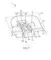
- FIG. 7 is a schematic diagram of an electronic apparatus 7 according to another preferred embodiment of the invention.
- the electronic apparatus 7 includes a casing 72 (shown in dashed lines) and the abovementioned two-side cable-arrangement structure 5.
- the casing 72 is engaged with the plate 52 and has a through hole 722; the detail of the engagement is not shown in FIG. 7 .
- the casing 72 of the electronic apparatus 7 usually forms an accommodating space for accommodating the plate 52 and other electronic components.
- the cable 6 is usually connected to an electronic component, is fixed by the two-side cable-arrangement structure 5, and passes through the through hole 722 to the exterior of the electronic apparatus 7.
- the cable 6 could be an FM antenna, a power cable or other cables.
- the position of the through hole 722 affects the pulling or pushing.
- the fixed portion of the second portion 64 of the cable 6 cannot be directly loosened by the pushing because there is the distance 74 between the projection of the through hole 722 and the cable outlet 566.
- the pushed cable 6 is stopped by the plate 52, so the second cable-arrangement structure 56 affect less the fixing effect on the cable 6.
- the cable-arrangement structures are disposed on the two sides of the plate of the two-side arrangement structure of the invention, so that the cable is double fixed by the cable-arrangement structures on the two sides, which provides the fixing effect in multiple directions on the cable.
- the portions of the cable fixed by the two cable-arrangement structures pull each other to produce a constraint force on both of the portions.
- the constraint force is conducive to preventing the cable from moving so as to enhance the fixing on the cable.
- the electronic apparatus with the two-side cable-arrangement structure of the invention can greatly reduce the effect of loosening the cable by the user pulling or pushing the exposed portion of the cable.
- the two-side cable-arrangement structure and the electronic apparatus with the two-side cable-arrangement structure of the invention solve the problem in the prior art that a user pulls or pushes a exposed portion of a cable fixed on a single cable-arrangement structure to loosen the cable, even damage the cable.
Landscapes
- Engineering & Computer Science (AREA)
- Microelectronics & Electronic Packaging (AREA)
- Insertion, Bundling And Securing Of Wires For Electric Apparatuses (AREA)
Abstract
Description
- The present invention relates to a two-side cable-arrangement structure and related electronic apparatus according to the pre-characterizing clauses of
claims - Most of electronic components in the electronic apparatus are integrated into a print circuit board, but some electronic modules are still electrically connected with cables. These connection cables or cables with other functions (such as antenna, power cable and so on) are often accommodated by hanging in the casing of the electronic apparatus. The electronic apparatus often includes single-side cable-arrangement structures disposed in the interior to arrange these cables. However, the arranged cables are only constrained in plane directions. These cables are easily pulled or pushed in a vertical direction perpendicular to the plane directions.
- Please refer to
FIG. 1 , which is a schematic diagram of a single-side cable-arrangement structure 1 according to the prior art. In this embodiment, the single-side cable-arrangement structure 1 is disposed at a corner of acasing 12 for fixing acable 2. The single-side cable-arrangement structure 1 consists mainly ofribs ribs passage 18 therebetween. Thecable 2 can be accommodated in thepassage 18. In addition, there areseveral protrusion spots passage 18 for fixing thecable 2 in thepassage 18 firmly. Thecable 2 passes through a throughhole 122 to the exterior of thecasing 12. In this embodiment, thecable 2 is constrained in plane directions, but when a user outside thecasing 12 pushes thecable 2 in, it is quite easy for thecable 2 to depart along adirection 124 perpendicular to thecasing 12 from thepassage 18, so that thewhole cable 2 departs from the single-side cable-arrangement structure 1. - Please refer to
FIG. 2 , which is a schematic diagram of the single-side cable-arrangement structure 1 on which anadhesive tape 20 is pasted according to the prior art. Theadhesive tape 20 is shown in dashed lines. In view of the problem of departing, a conventional method is to paste an adhesive tape over the whole single-side cable-arrangement structure 1 and thecable 2 additionally to prevent thecable 2 from departing, shown asFIG. 2 . However, as time goes by, the stickiness of theadhesive tape 20 decays till theadhesive tape 20 peels off. At this time, the abovementioned problem of departing also appears. - Please refer to
FIG. 3 , which is a schematic diagram of another single-side cable-arrangement structure 3 according to the prior art. In this embodiment, the single-side cable-arrangement structure 3 is used for fixing an electronic component 4 (such as infrared lens) andwires 42 connected thereto. The single-side cable-arrangement structure 3 usesribs 32 thereof to clip thewires 42 for the purpose of fixing the electronic component 4 and thewires 42 connected thereto. However, the way of fixing objects through the reciprocal resilient force induced by the deformation of theribs 32 under the compression by thewires 42 needs a coordinating structure size, so the way is usually applied to a special assembly of components (such as the assembly of the electronic component 4 and the wires), not widely to the fixing on a single cable. - This in mind, the present invention aims at providing a two-side cable-arrangement structure and an electronic apparatus therewith that use cable-arrangement structures on both sides of a plate to constrain a cable also in vertical directions perpendicular to the plate so that the cable can be firmly fixed on the plate.
- This is achieved by a two-side cable-arrangement structure and an electronic apparatus therewith according to
claims - As will be seen more clearly from the detailed description following below, the claimed two-side cable-arrangement structure for fixing a cable includes a plate, a first cable-arrangement structure, and a second cable-arrangement structure. The plate has a first side and a second side. The first side is opposite to the second side. The first cable-arrangement structure is disposed on the first side for fixing a first portion of the cable on the first side. The second cable-arrangement structure is disposed on the second side for fixing a second portion extending from the first portion of the cable on the second side.
- These and other objectives of the present invention will no doubt become obvious to those of ordinary skill in the art after reading the following detailed description of the preferred embodiment that is illustrated in the various figures and drawings.
- In the following, the invention is further illustrated by way of example, taking reference to the accompanying drawings. Thereof:
-
FIG. 1 is a schematic diagram of a single-side cable-arrangement structure according to the prior art, -
FIG. 2 is a schematic diagram of the single-side cable-arrangement structure on which an adhesive tape is pasted according to the prior art, -
FIG. 3 is a schematic diagram of another single-side cable-arrangement structure according to the prior art, -
FIG. 4 is a schematic diagram of a two-side cable-arrangement structure according to a preferred embodiment of the invention, -
FIG. 5 is a schematic diagram of the two-side cable-arrangement structure inFIG. 4 in another view according to the preferred embodiment of the invention, -
FIG. 6 is a schematic diagram of the first cable-arrangement structure according to another embodiment of the invention, and -
FIG. 7 is a schematic diagram of an electronic apparatus according to another preferred embodiment of the invention. - Please refer to
FIG. 4 andFIG. 5 .FIG. 4 is a schematic diagram of a two-side cable-arrangement structure 5 according to a preferred embodiment of the invention.FIG. 5 is a schematic diagram of the two-side cable-arrangement structure 5 inFIG. 4 in another view according to the preferred embodiment of the invention. The two-side cable-arrangement structure 5 is used for fixing a cable 6 (shown in dashed lines in the figures). The two-side cable-arrangement structure 5 includes aplate 52, a first cable-arrangement structure 54, and a second cable-arrangement structure 56. Theplate 52 includes afirst side 522 and asecond side 524. Thefirst side 522 is opposite to thesecond side 524. The first cable-arrangement structure 54 is disposed on thefirst side 522 for fixing afirst portion 62 of thecable 6 on thefirst side 522. The second cable-arrangement structure 56 is disposed on thesecond side 524 for fixing asecond portion 64 extending from thefirst portion 62 of thecable 6 on thesecond side 524. - Further, the first cable-
arrangement structure 54 substantially forms a cable passage which includes acable inlet 542, aholding part 544, and acable outlet 546. The second cable-arrangement structure 56 also substantially forms a cable passage which includes acable inlet 562, aholding part 564, and acable outlet 566. Thefirst portion 62 of thecable 6 passes through thecable inlet 542, thecable outlet 546 of the first cable-arrangement structure 54 and is fixed by theholding part 544 of the first cable-arrangement structure 54. In this embodiment, thecable outlet 546 of the first cable-arrangement structure 54 communicates with thecable inlet 562 of the second cable-arrangement structure 56, so thecable 6 directly crosses theplate 52 to from the first cable-arrangement structure 54 enter the second cable-arrangement structure 56; however, the invention is not limited to this. Thesecond portion 64 of thecable 6 passes through thecable inlet 562 and thecable outlet 566 of the second cable-arrangement structure 56 and is fixed by theholding part 564 of the second cable-arrangement structure 56. - In this embodiment, the
holding part 564 of the second cable-arrangement structure 56 is used for fixing thesecond portion 64 of thecable 6 so that the fixed portion of thesecond portion 64 of thecable 6 extends along afirst direction 66. In the operation of fixing thecable 6, because theholding part 564 has an open 5642, a user can dispose thesecond portion 64 of thecable 6 along a direction perpendicular to thefirst direction 66 from the open 5642 into theholding part 564, so that thesecond portion 64 of thecable 6 is fixed. In addition, there is adistance 58 along the direction perpendicular to thefirst direction 66 between thecable inlet 562 and theholding part 564. Therefore, after passing through thecable inlet 562 of the second cable-arrangement structure 56, thesecond portion 64 of thecable 6 extends along athird direction 68 and is bent to extend along afirst direction 66, so as to be fixed by theholding part 564. Furthermore, because thecable inlet 562 is shifted relatively to the open 5642, thecable inlet 562 is also conducive to preventing thecable 6 from departing from the open 5642. - In addition, because of the bending of the
cable 6 due to the traverse of thecable 6 across theplate 52, thecable 6 is bent several times to be fixed. Thereby, thecable 6 suffers multiple constraints, which increases the constraint force on thecable 6 produced by the first cable-arrangement structure 54 and a second cable-arrangement structure 56 when respectively fixing thecable 6 and is further conducive to fixing thecable 6. - In this embodiment, the
first portion 62 of thecable 6 is simply disposed in a narrow groove and fixed by the holdingpart 544 so that thefirst portion 62 of thecable 6 extends along asecond direction 70. Thesecond direction 70 is reverse to thefirst direction 66. In other words, thecable 6 extends mainly along thesecond direction 70 before entering the second cable-arrangement structure 56, and extends mainly along thefirst direction 66 reverse to thesecond direction 70 after entering the second cable-arrangement structure 56. Therefore, the extending path of thecable 6 is conducive to reducing the movement along the path and to fixing thecable 6. In this embodiment, the first cable-arrangement structure 54 and the second cable-arrangement structure 56 are not wholly symmetric, but the invention is also applied to a case of a symmetric structure without further descriptions. - It is added that, in this embodiment, the first cable-
arrangement structure 54 uses the similar fixing means to that used by the second cable-arrangement structure 56; that is, the holdingpart 544 compresses thecable 6 for preventing thecable 6 from departing from the cable passage formed by the first cable-arrangement structure 54. However, the invention is not limited to this. Please refer toFIG. 6 , which is a schematic diagram of the first cable-arrangement structure 54 according to another embodiment of the invention. A cable passage formed by the first cable-arrangement structure 54 is agroove 548, of which there is at least one protrusion spots 550 disposed on the two sides. Thefirst portion 62 of thecable 6 passes through thecable inlet 542 and thecable outlet 546 and is fixed in thegroove 548 by the protrusion spots 550 protruding toward thegroove 548. The holdingpart 544 inFIG. 4 and the protrusion spots 550 inFIG. 6 can also be used together without specially pointing out. - Please refer to
FIG. 5 . In the above embodiments, thecable 6 leaves the two-side cable-arrangement structure 5 from thecable outlet 566. Thecable 6 usually extends out of an electronic apparatus accommodating the two-side cable-arrangement structure 5, so a user may pull or push the exposedcable 6. When the user pulls the exposedcable 6, the holdingpart 564 can resist pulling thecable 6 from the second cable-arrangement structure 56. When the user pushes the exposedcable 6, thecable 6 is blocked by the wall at thecable outlet 566 of the second cable-arrangement structure 56 so that thesecond portion 64 of thecable 6 will not be loosened or depart from the holdingpart 564. Therefore, the two-side cable-arrangement structure 5 of the invention can fix thecable 6 efficiently and greatly reduce the possibility of the cable loosing due to pulling or pushing thecable 6 by the user. - Please refer to
FIG. 7 , which is a schematic diagram of anelectronic apparatus 7 according to another preferred embodiment of the invention. Theelectronic apparatus 7 includes a casing 72 (shown in dashed lines) and the abovementioned two-side cable-arrangement structure 5. Thecasing 72 is engaged with theplate 52 and has a throughhole 722; the detail of the engagement is not shown inFIG. 7 . Thecasing 72 of theelectronic apparatus 7 usually forms an accommodating space for accommodating theplate 52 and other electronic components. Thecable 6 is usually connected to an electronic component, is fixed by the two-side cable-arrangement structure 5, and passes through the throughhole 722 to the exterior of theelectronic apparatus 7. Thecable 6 could be an FM antenna, a power cable or other cables. - Because it is necessary for the user to pull or push the exposed portion of the
cable 6 through the throughhole 722, the position of the throughhole 722 affects the pulling or pushing. In this embodiment, there is adistance 74 along a direction perpendicular to thefirst direction 66 between the projection of the throughhole 722 on theplate 52 and the holdingpart 564 of the second cable-arrangement structure 56; that is, the projection is shifted by thedistance 74 from thefirst direction 66 along which thecable 6 is held by the holdingpart 564. Thereby, when the user pulls thecable 6, it is more difficult to pull thecable 6 to be loosened because thecable 6 is constrained by the throughhole 722 and then held by the holdingpart 564. When the user pushes thecable 6, the fixed portion of thesecond portion 64 of thecable 6 cannot be directly loosened by the pushing because there is thedistance 74 between the projection of the throughhole 722 and thecable outlet 566. In a general case, the pushedcable 6 is stopped by theplate 52, so the second cable-arrangement structure 56 affect less the fixing effect on thecable 6. - Therefore, the cable-arrangement structures are disposed on the two sides of the plate of the two-side arrangement structure of the invention, so that the cable is double fixed by the cable-arrangement structures on the two sides, which provides the fixing effect in multiple directions on the cable. The portions of the cable fixed by the two cable-arrangement structures pull each other to produce a constraint force on both of the portions. The constraint force is conducive to preventing the cable from moving so as to enhance the fixing on the cable. In addition, besides having the abovementioned fixing effect on the cable, the electronic apparatus with the two-side cable-arrangement structure of the invention can greatly reduce the effect of loosening the cable by the user pulling or pushing the exposed portion of the cable. Therefore, the two-side cable-arrangement structure and the electronic apparatus with the two-side cable-arrangement structure of the invention solve the problem in the prior art that a user pulls or pushes a exposed portion of a cable fixed on a single cable-arrangement structure to loosen the cable, even damage the cable.
- Those skilled in the art will readily observe that numerous modifications and alterations of the device and method may be made while retaining the teachings of the invention. Accordingly, the above disclosure should be construed as limited only by the metes and bounds of the appended claims.
Claims (19)
- A two-side cable-arrangement structure (5) for fixing a cable (6), characterized in that the two-side cable-arrangement structure (5) comprising:a plate (52) having a first side (522) and a second side (524), the first side (522) being opposite to the second side (524) ;a first cable-arrangement structure (54) disposed on the first side (522) for fixing a first portion (62) of the cable (6) on the first side (522); anda second cable-arrangement structure (56) disposed on the second side (524) for fixing a second portion (64) extending from the first portion (62) of the cable (6) on the second side (524).
- The two-side cable-arrangement structure (5) of claim 1 characterized in that the first cable-arrangement structure (54) comprises a cable inlet (542), a holding part (544), and a cable outlet (546), and the first portion (62) of the cable (6) passes through the cable inlet (542) and the cable outlet (546) and is fixed by the holding part (544).
- The two-side cable-arrangement structure (5) of claim 1 characterized in that the first cable-arrangement structure (54) comprises a cable inlet (542), a groove (548), and a cable outlet (546), and the first portion (62) of the cable (6) passes through the cable inlet (542) and the cable outlet (546) and is fixed in the groove (548).
- The two-side cable-arrangement structure (5) of claim 3 characterized in that at least one protrusion spot (550) is disposed on a side of the groove (548) for fixing the first portion (62) of the cable (6) in the groove (548).
- The two-side cable-arrangement structure (5) of claim 1 characterized in that the second cable-arrangement structure (56) comprises a cable inlet (562), a holding part (564), and a cable outlet (566), and the second portion (64) of the cable (6) passes through the cable inlet (562) and the cable outlet (566) and is fixed by the holding part (564).
- The two-side cable-arrangement structure (5) of claim 5 characterized in that the holding part (564) is used for fixing the second portion (64) of the cable (6) so that the fixed portion of the second portion (64) of the cable (6) extends along a first direction (66), and there is a distance (58) along a direction perpendicular to the first direction (66) between the cable inlet (562) and the holding part (564).
- The two-side cable-arrangement structure (5) of claim 6 characterized in that the first cable-arrangement structure (54) is used for fixing the first portion (62) of the cable (6) so that the fixed portion of the first portion (62) of the cable (6) extends along a second direction (70), and the second direction (70) is reverse to the first direction (66).
- The two-side cable-arrangement structure (5) of claim 6 characterized in that the holding part (564) has an open (5642) so that the second portion (64) of the cable (6) along the direction perpendicular to the first direction (66) from the open (5642) enters the holding part (564) to be fixed.
- The two-side cable-arrangement structure (5) of claim 5 characterized in that the cable inlet (562) communicates directly with a cable outlet (546) of the first cable-arrangement structure (54).
- An electronic apparatus (7) with two-side cable-arrangement structure, the electronic apparatus (7) comprising:a cable (6) having a first portion (62) and a second portion (64) extending from the first portion (62);characterized by:a plate (52) having a first side (522) and a second side (524), the first side (522) being opposite to the second side (524) ;a first cable-arrangement structure (54) disposed on the first side (522) for fixing the first portion (62) on the first side (522);a second cable-arrangement structure (56) disposed on the second side (524) for fixing the second portion (64) on the second side (524); anda casing (72) being engaged with the plate (52) and having a through hole (722), the cable (6) passing through the through hole (722).
- The electronic apparatus (7) of claim 10 characterized in that the first cable-arrangement structure (54) comprises a cable inlet (542), a holding part (544), and a cable outlet (546), and the first portion (62) of the cable (6) passes through the cable inlet (542) and the cable outlet (546) and is fixed by the holding part (544).
- The electronic apparatus (7) of claim 10 characterized in that the first cable-arrangement structure (54) comprises a cable inlet (542), a groove (548), and a cable outlet (546), and the first portion (62) of the cable (6) passes through the cable inlet (542) and the cable outlet (546) and is fixed in the groove (548).
- The electronic apparatus (7) of claim 12 characterized in that at least one protrusion spot (550) is disposed on a side of the groove (548) for fixing the first portion (62) of the cable (6) in the groove (548).
- The electronic apparatus (7) of claim 10 characterized in that the second cable-arrangement structure (56) comprises a cable inlet (562), a holding part (564), and a cable outlet (566), and the second portion (64) of the cable (6) passes through the cable inlet (562) and the cable outlet (566) and is fixed by the holding part (564).
- The electronic apparatus (7) of claim 14 characterized in that the second portion (64) of the cable (6) passes through the cable inlet (562), extends along a third direction (68), and extends along a first direction (66) after being bent, so as to be fixed by the holding part (564).
- The electronic apparatus (7) of claim 15 characterized in that the first portion (62) of the cable (6) extends along a second direction (70), and the second direction (70) is reverse to the first direction (66).
- The electronic apparatus (7) of claim 15 characterized in that the holding part (564) has an open (5642), and the second portion (64) of the cable (6) along the third direction (68) perpendicular to the first direction (66) from the open (5642) enters the holding part (564) to be fixed.
- The electronic apparatus (7) of claim 17 characterized in that there is a distance (74) along a direction perpendicular to the first direction (66) between a projection of the through hole (722) onto the plate (52) and the holding part (564).
- The electronic apparatus (7) of claim 14 characterized in that the cable inlet (562) communicates directly with a cable outlet (546) of the first cable-arrangement structure (54).
Applications Claiming Priority (1)
| Application Number | Priority Date | Filing Date | Title |
|---|---|---|---|
| TW099121824A TWI433637B (en) | 2010-07-02 | 2010-07-02 | Two-side cable-arrangement structure and electronic apparatus therewith |
Publications (2)
| Publication Number | Publication Date |
|---|---|
| EP2403327A2 true EP2403327A2 (en) | 2012-01-04 |
| EP2403327A3 EP2403327A3 (en) | 2014-06-11 |
Family
ID=44653946
Family Applications (1)
| Application Number | Title | Priority Date | Filing Date |
|---|---|---|---|
| EP11005265.1A Withdrawn EP2403327A3 (en) | 2010-07-02 | 2011-06-28 | Two-side cable-arrangement structure and electronic apparatus therewith |
Country Status (3)
| Country | Link |
|---|---|
| US (1) | US8624120B2 (en) |
| EP (1) | EP2403327A3 (en) |
| TW (1) | TWI433637B (en) |
Cited By (4)
| Publication number | Priority date | Publication date | Assignee | Title |
|---|---|---|---|---|
| WO2017043663A1 (en) | 2015-09-11 | 2017-03-16 | 株式会社フジクラ | Antenna device |
| EP3246987A1 (en) | 2016-05-20 | 2017-11-22 | Fujikura Ltd. | Antenna device and method for manufacturing the same |
| EP3246988A1 (en) | 2016-05-20 | 2017-11-22 | Fujikura Ltd. | Antenna device and method for manufacturing the same |
| US10170825B2 (en) | 2015-09-11 | 2019-01-01 | Fujikura Ltd. | Antenna device |
Families Citing this family (4)
| Publication number | Priority date | Publication date | Assignee | Title |
|---|---|---|---|---|
| JP5579571B2 (en) * | 2010-10-26 | 2014-08-27 | 株式会社マキタ | Power cord arrangement structure |
| JP6482219B2 (en) | 2014-09-19 | 2019-03-13 | キヤノン株式会社 | Image forming apparatus and image forming system |
| WO2017103738A1 (en) * | 2015-12-14 | 2017-06-22 | Sabic Global Technologies B.V. | Conversion of methane to ethylene comprising integration with the in-situ ethane cracking and direct conversion of co2 byproduct to methanol |
| TWM589410U (en) * | 2019-11-12 | 2020-01-11 | 和碩聯合科技股份有限公司 | Circuit board and its cable management structure |
Family Cites Families (11)
| Publication number | Priority date | Publication date | Assignee | Title |
|---|---|---|---|---|
| US2309741A (en) * | 1940-11-19 | 1943-02-02 | United Carr Fastener Corp | Cord securing device |
| US3419670A (en) * | 1966-11-28 | 1968-12-31 | Admiral Corp | Strain relief for line cords |
| DE7809938U1 (en) * | 1978-04-04 | 1978-08-17 | Standard Elektrik Lorenz Ag, 7000 Stuttgart | Cable holder |
| FR2558016B1 (en) * | 1984-01-06 | 1986-08-22 | Moulins Electronique Indle | SECURITY THREAD FOR ELECTRIC HOUSEHOLD APPLIANCE AND ELECTRIC APPARATUS DESIGNED TO RECEIVE SUCH A THREAD |
| GB8720103D0 (en) * | 1987-08-26 | 1987-09-30 | British Telecomm | Corner guide |
| FR2696214B1 (en) * | 1992-09-25 | 1994-11-04 | Alcatel Business Systems | Fixing system for flexible tubular element. |
| US5952616A (en) * | 1995-09-22 | 1999-09-14 | Hughes Electronics Corporation | Cable retainer with retaining surfaces having offset protrusions |
| JP2003259535A (en) * | 2002-03-07 | 2003-09-12 | Yazaki Corp | Wire laying structure for flat circuit body |
| JP4762002B2 (en) * | 2006-02-27 | 2011-08-31 | 株式会社東芝 | Electronics |
| TWI293412B (en) | 2006-04-21 | 2008-02-11 | Foxconn Tech Co Ltd | Heat dissipation device |
| TWM304947U (en) | 2006-06-19 | 2007-01-21 | Aurora Corp | Combined cabinet with wire organizing function |
-
2010
- 2010-07-02 TW TW099121824A patent/TWI433637B/en active
- 2010-11-24 US US12/953,466 patent/US8624120B2/en active Active
-
2011
- 2011-06-28 EP EP11005265.1A patent/EP2403327A3/en not_active Withdrawn
Non-Patent Citations (1)
| Title |
|---|
| None |
Cited By (4)
| Publication number | Priority date | Publication date | Assignee | Title |
|---|---|---|---|---|
| WO2017043663A1 (en) | 2015-09-11 | 2017-03-16 | 株式会社フジクラ | Antenna device |
| US10170825B2 (en) | 2015-09-11 | 2019-01-01 | Fujikura Ltd. | Antenna device |
| EP3246987A1 (en) | 2016-05-20 | 2017-11-22 | Fujikura Ltd. | Antenna device and method for manufacturing the same |
| EP3246988A1 (en) | 2016-05-20 | 2017-11-22 | Fujikura Ltd. | Antenna device and method for manufacturing the same |
Also Published As
| Publication number | Publication date |
|---|---|
| US20120000702A1 (en) | 2012-01-05 |
| TWI433637B (en) | 2014-04-01 |
| US8624120B2 (en) | 2014-01-07 |
| EP2403327A3 (en) | 2014-06-11 |
| TW201204221A (en) | 2012-01-16 |
Similar Documents
| Publication | Publication Date | Title |
|---|---|---|
| EP2403327A2 (en) | Two-side cable-arrangement structure and electronic apparatus therewith | |
| US10791635B2 (en) | Fixing mechanism and related electronic apparatus | |
| US8625258B2 (en) | Mounting apparatus for expansion card | |
| TW201345377A (en) | Expansion module and fixing frame thereof | |
| JP2006238557A (en) | Electronic equipment having cable holder | |
| US8247707B2 (en) | Shielding assembly | |
| US20080169391A1 (en) | Electronic device and its fixing module capable of fastening a board | |
| JP2006228872A (en) | Method and device of fixing wire material | |
| TWI441986B (en) | Fixing mechanism for fixing a component | |
| JP2010251229A (en) | Electronic equipment | |
| US8941984B2 (en) | Storage bridge bay canister attachment system and method of forming same | |
| JP2005133925A (en) | Fixture | |
| US20140321081A1 (en) | Circuit board mounting apparatus | |
| US7819689B2 (en) | Electrical connector assembly with pick up cap alternatively attached to a housing or a cover | |
| US8784125B2 (en) | Side retainer assembly for heat sink and memory modules | |
| JP2011124414A (en) | Electronic device | |
| JPS6029188Y2 (en) | Soldering structure of flexible printed circuit board | |
| JP4916398B2 (en) | Electrical connection device | |
| WO2015159701A1 (en) | Connector and electronic equipment | |
| JP2010199322A (en) | Substrate support structure and electronic device | |
| US20140140017A1 (en) | Electronic device with card bracket | |
| JP3301193B2 (en) | Printed circuit board device | |
| JPS5816227Y2 (en) | Parts mounting device | |
| US20140002997A1 (en) | Side lock assembly for heat sink and memory modules | |
| US20140002981A1 (en) | Heat sink for memory modules |
Legal Events
| Date | Code | Title | Description |
|---|---|---|---|
| AK | Designated contracting states |
Kind code of ref document: A2 Designated state(s): AL AT BE BG CH CY CZ DE DK EE ES FI FR GB GR HR HU IE IS IT LI LT LU LV MC MK MT NL NO PL PT RO RS SE SI SK SM TR |
|
| AX | Request for extension of the european patent |
Extension state: BA ME |
|
| PUAI | Public reference made under article 153(3) epc to a published international application that has entered the european phase |
Free format text: ORIGINAL CODE: 0009012 |
|
| PUAL | Search report despatched |
Free format text: ORIGINAL CODE: 0009013 |
|
| AK | Designated contracting states |
Kind code of ref document: A3 Designated state(s): AL AT BE BG CH CY CZ DE DK EE ES FI FR GB GR HR HU IE IS IT LI LT LU LV MC MK MT NL NO PL PT RO RS SE SI SK SM TR |
|
| AX | Request for extension of the european patent |
Extension state: BA ME |
|
| RIC1 | Information provided on ipc code assigned before grant |
Ipc: H05K 7/08 20060101ALI20140505BHEP Ipc: H05K 7/14 20060101ALI20140505BHEP Ipc: H05K 7/06 20060101ALI20140505BHEP Ipc: H05K 7/02 20060101AFI20140505BHEP Ipc: H02G 3/06 20060101ALI20140505BHEP |
|
| 17P | Request for examination filed |
Effective date: 20141211 |
|
| RBV | Designated contracting states (corrected) |
Designated state(s): AL AT BE BG CH CY CZ DE DK EE ES FI FR GB GR HR HU IE IS IT LI LT LU LV MC MK MT NL NO PL PT RO RS SE SI SK SM TR |
|
| GRAP | Despatch of communication of intention to grant a patent |
Free format text: ORIGINAL CODE: EPIDOSNIGR1 |
|
| RIC1 | Information provided on ipc code assigned before grant |
Ipc: H02G 3/30 20060101ALI20151210BHEP Ipc: H05K 7/14 20060101ALI20151210BHEP Ipc: H05K 7/08 20060101ALI20151210BHEP Ipc: H05K 7/06 20060101ALI20151210BHEP Ipc: H05K 7/02 20060101AFI20151210BHEP |
|
| INTG | Intention to grant announced |
Effective date: 20160112 |
|
| STAA | Information on the status of an ep patent application or granted ep patent |
Free format text: STATUS: THE APPLICATION IS DEEMED TO BE WITHDRAWN |
|
| 18D | Application deemed to be withdrawn |
Effective date: 20160524 |