EP2402637A1 - Flow module port fitting - Google Patents
Flow module port fitting Download PDFInfo
- Publication number
- EP2402637A1 EP2402637A1 EP20100168141 EP10168141A EP2402637A1 EP 2402637 A1 EP2402637 A1 EP 2402637A1 EP 20100168141 EP20100168141 EP 20100168141 EP 10168141 A EP10168141 A EP 10168141A EP 2402637 A1 EP2402637 A1 EP 2402637A1
- Authority
- EP
- European Patent Office
- Prior art keywords
- flow module
- port
- head
- port fitting
- end portion
- Prior art date
- Legal status (The legal status is an assumption and is not a legal conclusion. Google has not performed a legal analysis and makes no representation as to the accuracy of the status listed.)
- Pending
Links
- 239000000463 material Substances 0.000 claims description 3
- 239000012530 fluid Substances 0.000 description 4
- 239000007789 gas Substances 0.000 description 3
- 238000007789 sealing Methods 0.000 description 3
- 230000000903 blocking effect Effects 0.000 description 2
- 238000010276 construction Methods 0.000 description 1
- 238000000034 method Methods 0.000 description 1
- 238000012986 modification Methods 0.000 description 1
- 230000004048 modification Effects 0.000 description 1
- 239000000126 substance Substances 0.000 description 1
Images

Classifications
-
- F—MECHANICAL ENGINEERING; LIGHTING; HEATING; WEAPONS; BLASTING
- F17—STORING OR DISTRIBUTING GASES OR LIQUIDS
- F17D—PIPE-LINE SYSTEMS; PIPE-LINES
- F17D1/00—Pipe-line systems
-
- F—MECHANICAL ENGINEERING; LIGHTING; HEATING; WEAPONS; BLASTING
- F16—ENGINEERING ELEMENTS AND UNITS; GENERAL MEASURES FOR PRODUCING AND MAINTAINING EFFECTIVE FUNCTIONING OF MACHINES OR INSTALLATIONS; THERMAL INSULATION IN GENERAL
- F16L—PIPES; JOINTS OR FITTINGS FOR PIPES; SUPPORTS FOR PIPES, CABLES OR PROTECTIVE TUBING; MEANS FOR THERMAL INSULATION IN GENERAL
- F16L15/00—Screw-threaded joints; Forms of screw-threads for such joints
- F16L15/04—Screw-threaded joints; Forms of screw-threads for such joints with additional sealings
-
- F—MECHANICAL ENGINEERING; LIGHTING; HEATING; WEAPONS; BLASTING
- F16—ENGINEERING ELEMENTS AND UNITS; GENERAL MEASURES FOR PRODUCING AND MAINTAINING EFFECTIVE FUNCTIONING OF MACHINES OR INSTALLATIONS; THERMAL INSULATION IN GENERAL
- F16L—PIPES; JOINTS OR FITTINGS FOR PIPES; SUPPORTS FOR PIPES, CABLES OR PROTECTIVE TUBING; MEANS FOR THERMAL INSULATION IN GENERAL
- F16L55/00—Devices or appurtenances for use in, or in connection with, pipes or pipe systems
- F16L55/10—Means for stopping flow in pipes or hoses
- F16L55/11—Plugs
- F16L55/1108—Plugs fixed by screwing or by means of a screw-threaded ring
-
- Y—GENERAL TAGGING OF NEW TECHNOLOGICAL DEVELOPMENTS; GENERAL TAGGING OF CROSS-SECTIONAL TECHNOLOGIES SPANNING OVER SEVERAL SECTIONS OF THE IPC; TECHNICAL SUBJECTS COVERED BY FORMER USPC CROSS-REFERENCE ART COLLECTIONS [XRACs] AND DIGESTS
- Y10—TECHNICAL SUBJECTS COVERED BY FORMER USPC
- Y10T—TECHNICAL SUBJECTS COVERED BY FORMER US CLASSIFICATION
- Y10T137/00—Fluid handling
- Y10T137/598—With repair, tapping, assembly, or disassembly means
Definitions
- the present invention relates to a flow module port fitting.
- the present invention relates to flow module port fittings attachable to ports in flow modules for different purposes. Such purposes might be introducing or removing fluids or gases to or from said flow module or blocking said ports. Problems often arising with such constructions are generally leakage and soiling of dead ends and crevices formed when said fittings are mounted in the ports of the module.
- Flow modules in which the present invention may be fitted are e.g. described in the international patent applications PCT/SE2010/050397 , WO 2007/050013 and WO 2007/073281 .
- the present invention therefore aims to provide a port fitting which reduces the disadvantages of the problems mentioned above.
- the fitting comprises a head, and a shaft with a centre axis, attached to the head, wherein the shaft has a first and a second end portion and comprising, at its first end portion attached to the head, a set of threads, and a ring-formed seal arranged in a ring-formed groove either externally on said shaft at the second end portion facing away from the head, or in the short side of said second end portion, and protruding from said groove.
- the ring-formed groove is arranged in a tapered or rounded part of said second end portion closest to the tip.
- said port fitting has a central boring through the whole length of said port fitting aligned with said axis.
- said port fitting has a central boring aligned with said axis leading through the head and the shaft to the second end portion but not opening up said boring in said second end instead leaving a thin wall of material.
- a spring-loaded sensor is mounted in said boring.
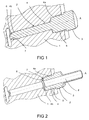
- FIG. 1 is an example of a port fitting depicted, which has, when mounted, the function of blocking a port communicating with the inside of a flow module.
- Said port fitting 2 comprises a head 3 which has a hexagonal form for facilitating application of said port fitting 2 in a port of a flow module 1.
- a first end 4a of a shaft 4 attached which shaft 4 has a circular cross section and a central axis A.
- a set of threads 5 is arranged adapted to be screwed into a complimentary set of threads in a port of said flow module 1.
- a second end portion 4b of said shaft 4 is free and the part closest to the end is slightly tapered or rounded towards the tip.
- a ring-formed groove 7 is arranged in the envelope surface of said tapered or rounded part of the end portion 4b of the shaft 4 close to said second end.
- the diameter of the cross section of said second end portion 4b is smaller corresponding to a portion of said port in the flow module also with smaller diameter.
- a ring-formed port seal 6 of O-ring-type arranged. Said port seal 6 may have other cross-sections, e.g. oval or rectangular.
- the diameter or the width of the cross-section is larger than the depth of the groove 7 thus causing the seal to protrude from said envelope surface.
- the protruding seal 6 When fitted in a port of a flow module as is disclosed in fig. 1 the protruding seal 6 rests against a ring-formed lip in said port and thus seals any gaps between the assembly and the port seen from the flow channel on the inside of the flow module. With the threaded fitting in the port a tight enough sealing function is provided for. The O-ring seal will be flushed with process fluid in the flow channel on the inside of the flow module.
- FIG. 2 is an example of a port fitting depicted, which has, when fitted, the function of introduce or remove fluids or gases to or from said flow module.
- Said port fitting 2 comprises a head 3 which has a hexagonal form for facilitating application of said port fitting 2 in a port of a flow module 1.
- a first end 4a of a shaft 4 attached which shaft 4 has a circular cross section and a central axis A.
- a set of threads 5 is arranged adapted to be screwed into a complimentary set of threads in a port of said flow module 1.
- a second end portion 4b of said shaft 4 is free and there is a ring-formed groove 7 in the short end surface of the shaft 4.
- a ring-formed port seal 6 of O-ring-type is arranged in said ring-formed groove 7 arranged.
- Said port seal 6 may have other cross-sections, e.g. oval or rectangular.
- the diameter or the width of the cross-section is larger than the depth of the groove 7 thus causing the seal to protrude from said short end surface.
- the port fitting 2 has a central boring 8 through the whole length of said port fitting aligned with said axis A and thus providing a channel through which substances may be introduced into or removed from the interior of said flow module.
- the protruding port seal 6 When fitted in a port of a flow module as is disclosed in fig. 2 the protruding port seal 6 rests against a ring-formed surface of said port where the said portion of smaller diameter starts and thus seals the port from the inside of the flow module. With the threaded port fitting in the port a tight enough sealing function is provided.
- FIG. 3 is an example of a port fitting 2 depicted, which has, when fitted, the function of providing the possibility to arrange sensors in said flow module.
- Said port fitting 2 comprises a head 3 which has a hexagonal form for facilitating application of said port fitting 2 in a port of a flow module 1.
- a set of threads 5 is arranged adapted to be screwed into a complimentary set of threads in a port of said flow module 1.
- a second end portion 4b of said shaft 4 is free and the part closest to the end it is slightly tapered towards the tip.
- a ring-formed groove 7 is arranged in the envelope surface of said tapered part of the end portion 4b of the shaft 4 close to said second end.
- the diameter of the cross section of said second end portion 4b is smaller corresponding to a portion of said port in the flow module also with smaller diameter.
- a ring-formed seal 6 of O-ring-type arranged. Said seal 6 may have other cross-sections, e.g. oval or rectangular.
- the diameter or the width of the cross-section of the seal 6 is larger than the depth of the groove 7 thus causing the seal to protrude from said envelope surface.
- the protruding seal 6 When fitted in a port of a flow module as is disclosed in fig. 3 the protruding seal 6 rests against a ring-formed lip in said port and thus seals the gap between the port fitting and the port from the inside of the flow module. With the threaded port fitting in the port a tight enough sealing function is provided.
- Said port fitting 2 has a central boring 9 aligned with said axis A leading through the head 3 and the shaft 4 to the free end but not opening up said boring 9 in said second end instead leaving a thin wall of material.
- This boring 9 may then be used for mounting sensors e.g. temperature sensors.
- the boring 9 may in its end with the head 3 have interior threads complimenting exterior threads on a sensor arrangement.
- Such a sensor may be provided with a coaxial spring, preferably a coil spring, arranged against a stop constituted by the bottom of a head of the sensor which head is formed as a bolt or screw head and used to screw the sensor in place in the boring 9. The spring is thus brought against a stop formed in the boring 9, e.g. a beginning of a part with smaller diameter. The sensor when mounted in the boring is thus spring-loaded.
Landscapes
- Engineering & Computer Science (AREA)
- General Engineering & Computer Science (AREA)
- Mechanical Engineering (AREA)
- Measuring Volume Flow (AREA)
Abstract
A flow module port fitting (2) comprises a head (3), and a shaft (4) with an centre axis (A), attached to the head (3), wherein the shaft (4) has a first (4a) and a second end portion (4b) and comprises, at its first end portion (4a) attached to the head (3), a set of threads (5), and a ring-formed seal (6) arranged in a ring-formed groove (7) either externally on said shaft (4) at the second end (4b) facing away from the head (3), or in a short side (4c) of said second end (4b), and protruding from said groove (7). The invention provides a seal of flow module ports that minimizes leakage and dirt to find its way into gaps between the port and the port fitting.
Description
- The present invention relates to a flow module port fitting.
- The present invention relates to flow module port fittings attachable to ports in flow modules for different purposes. Such purposes might be introducing or removing fluids or gases to or from said flow module or blocking said ports. Problems often arising with such constructions are generally leakage and soiling of dead ends and crevices formed when said fittings are mounted in the ports of the module. Flow modules in which the present invention may be fitted are e.g. described in the international patent applications
PCT/SE2010/050397 WO 2007/050013 andWO 2007/073281 . - The present invention therefore aims to provide a port fitting which reduces the disadvantages of the problems mentioned above.
- The present invention is therefore characterized by that the fitting comprises a head, and a shaft with a centre axis, attached to the head, wherein the shaft has a first and a second end portion and comprising, at its first end portion attached to the head, a set of threads, and a ring-formed seal arranged in a ring-formed groove either externally on said shaft at the second end portion facing away from the head, or in the short side of said second end portion, and protruding from said groove.
- In another embodiment of the present invention the ring-formed groove is arranged in a tapered or rounded part of said second end portion closest to the tip.
- In yet another embodiment of the present invention said port fitting has a central boring through the whole length of said port fitting aligned with said axis.
- In another embodiment of the present invention said port fitting has a central boring aligned with said axis leading through the head and the shaft to the second end portion but not opening up said boring in said second end instead leaving a thin wall of material.
- In another embodiment of the present invention a spring-loaded sensor is mounted in said boring.
- Other aspects and advantages of the invention will, with reference to the accompanying drawings, be presented in the following detailed description of embodiment s of the invention.
-
-
Fig. 1 discloses a flow module port fitting according to the present invention adapted to be mounted in and block a port of a flow module. -
Fig. 2 discloses a flow module port fitting according to the present invention adapted to provide the possibility to introduce or remove fluids or gases to or from said flow module. -
Fig. 3 discloses a flow module port fitting according to the present invention adapted to provide the possibility to arrange sensors in said flow module. - In
fig. 1 is an example of a port fitting depicted, which has, when mounted, the function of blocking a port communicating with the inside of a flow module. Saidport fitting 2 comprises ahead 3 which has a hexagonal form for facilitating application of said port fitting 2 in a port of aflow module 1. - To the
head 3 is afirst end 4a of ashaft 4 attached whichshaft 4 has a circular cross section and a central axis A. At saidfirst end portion 4a a set ofthreads 5 is arranged adapted to be screwed into a complimentary set of threads in a port of saidflow module 1. Asecond end portion 4b of saidshaft 4 is free and the part closest to the end is slightly tapered or rounded towards the tip. A ring-formedgroove 7 is arranged in the envelope surface of said tapered or rounded part of theend portion 4b of theshaft 4 close to said second end. The diameter of the cross section of saidsecond end portion 4b is smaller corresponding to a portion of said port in the flow module also with smaller diameter. In said ring-formedgroove 7 is a ring-formedport seal 6 of O-ring-type arranged. Saidport seal 6 may have other cross-sections, e.g. oval or rectangular. - The diameter or the width of the cross-section is larger than the depth of the
groove 7 thus causing the seal to protrude from said envelope surface. - When fitted in a port of a flow module as is disclosed in
fig. 1 the protrudingseal 6 rests against a ring-formed lip in said port and thus seals any gaps between the assembly and the port seen from the flow channel on the inside of the flow module. With the threaded fitting in the port a tight enough sealing function is provided for. The O-ring seal will be flushed with process fluid in the flow channel on the inside of the flow module. - In
fig. 2 is an example of a port fitting depicted, which has, when fitted, the function of introduce or remove fluids or gases to or from said flow module. Saidport fitting 2 comprises ahead 3 which has a hexagonal form for facilitating application of said port fitting 2 in a port of aflow module 1. - To the
head 3 is afirst end 4a of ashaft 4 attached whichshaft 4 has a circular cross section and a central axis A. At saidfirst end portion 4a a set ofthreads 5 is arranged adapted to be screwed into a complimentary set of threads in a port of saidflow module 1. Asecond end portion 4b of saidshaft 4 is free and there is a ring-formedgroove 7 in the short end surface of theshaft 4. In said ring-formed groove 7 a ring-formedport seal 6 of O-ring-type is arranged. Saidport seal 6 may have other cross-sections, e.g. oval or rectangular. - The diameter or the width of the cross-section is larger than the depth of the
groove 7 thus causing the seal to protrude from said short end surface. - The
port fitting 2 has acentral boring 8 through the whole length of said port fitting aligned with said axis A and thus providing a channel through which substances may be introduced into or removed from the interior of said flow module. - When fitted in a port of a flow module as is disclosed in
fig. 2 theprotruding port seal 6 rests against a ring-formed surface of said port where the said portion of smaller diameter starts and thus seals the port from the inside of the flow module. With the threaded port fitting in the port a tight enough sealing function is provided. - In
fig. 3 is an example of aport fitting 2 depicted, which has, when fitted, the function of providing the possibility to arrange sensors in said flow module. Saidport fitting 2 comprises ahead 3 which has a hexagonal form for facilitating application of said port fitting 2 in a port of aflow module 1. - To the
head 3 is afirst end 4a of ashaft 4 attached whichshaft 4 has a circular cross section. At saidfirst end portion 4a a set ofthreads 5 is arranged adapted to be screwed into a complimentary set of threads in a port of saidflow module 1. Asecond end portion 4b of saidshaft 4 is free and the part closest to the end it is slightly tapered towards the tip. A ring-formedgroove 7 is arranged in the envelope surface of said tapered part of theend portion 4b of theshaft 4 close to said second end. The diameter of the cross section of saidsecond end portion 4b is smaller corresponding to a portion of said port in the flow module also with smaller diameter. In said ring-formedgroove 7 is a ring-formedseal 6 of O-ring-type arranged. Saidseal 6 may have other cross-sections, e.g. oval or rectangular. - The diameter or the width of the cross-section of the
seal 6 is larger than the depth of thegroove 7 thus causing the seal to protrude from said envelope surface. - When fitted in a port of a flow module as is disclosed in
fig. 3 the protrudingseal 6 rests against a ring-formed lip in said port and thus seals the gap between the port fitting and the port from the inside of the flow module. With the threaded port fitting in the port a tight enough sealing function is provided. - Said port fitting 2 has a
central boring 9 aligned with said axis A leading through thehead 3 and theshaft 4 to the free end but not opening up said boring 9 in said second end instead leaving a thin wall of material. This boring 9 may then be used for mounting sensors e.g. temperature sensors. For facilitating the mounting of such sensors the boring 9 may in its end with thehead 3 have interior threads complimenting exterior threads on a sensor arrangement. Such a sensor may be provided with a coaxial spring, preferably a coil spring, arranged against a stop constituted by the bottom of a head of the sensor which head is formed as a bolt or screw head and used to screw the sensor in place in the boring 9. The spring is thus brought against a stop formed in the boring 9, e.g. a beginning of a part with smaller diameter. The sensor when mounted in the boring is thus spring-loaded. - The above detailed description is not limited to the mentioned embodiments of the invention but to a person skilled in the art there are several modifications possible within the scope of the claimed invention.
Claims (5)
- A flow module port fitting (2) comprising a head (3), and a shaft (4) with an centre axis (A), attached to the head (3), wherein the shaft (4) has a first (4a) and a second end portion (4b) and comprising, at its first end portion (4a) attached to the head (3), a set of threads (5), and a ring-formed seal (6) arranged in a ring-formed groove (7) either externally on said shaft (4) at the second end portion (4b) facing away from the head (3), or in the short side of said second end portion (4b), and protruding from said groove (7).
- A flow module port fitting according to claim 1, wherein the ring-formed groove is arranged in a tapered or rounded part of said second end portion (4b) closest to the tip.
- A flow module port fitting according to one of claims 1 and 2, wherein said port fitting (2) has a central boring (8) through the whole length of said port fitting aligned with said axis (A).
- A flow module port fitting according to one of claims 1 and 2, wherein said port fitting (2) has a central boring (9) aligned with said axis (A) leading through the head (3) and the shaft (4) to the second end portion (4b) but not opening up said boring (9) in said second end instead leaving a thin wall of material.
- A flow module port fitting according to claim 4, wherein a spring-loaded sensor is mounted in said boring (9).
Priority Applications (5)
| Application Number | Priority Date | Filing Date | Title |
|---|---|---|---|
| EP20100168141 EP2402637A1 (en) | 2010-07-01 | 2010-07-01 | Flow module port fitting |
| CN201180033014.8A CN102959303B (en) | 2010-07-01 | 2011-06-29 | Flow module port fitting |
| EP11732527.4A EP2588792A1 (en) | 2010-07-01 | 2011-06-29 | Flow module port fitting |
| PCT/SE2011/050865 WO2012002892A1 (en) | 2010-07-01 | 2011-06-29 | Flow module port fitting |
| US13/807,770 US9500319B2 (en) | 2010-07-01 | 2011-06-29 | Flow module port fitting |
Applications Claiming Priority (1)
| Application Number | Priority Date | Filing Date | Title |
|---|---|---|---|
| EP20100168141 EP2402637A1 (en) | 2010-07-01 | 2010-07-01 | Flow module port fitting |
Publications (1)
| Publication Number | Publication Date |
|---|---|
| EP2402637A1 true EP2402637A1 (en) | 2012-01-04 |
Family
ID=42646514
Family Applications (2)
| Application Number | Title | Priority Date | Filing Date |
|---|---|---|---|
| EP20100168141 Pending EP2402637A1 (en) | 2010-07-01 | 2010-07-01 | Flow module port fitting |
| EP11732527.4A Withdrawn EP2588792A1 (en) | 2010-07-01 | 2011-06-29 | Flow module port fitting |
Family Applications After (1)
| Application Number | Title | Priority Date | Filing Date |
|---|---|---|---|
| EP11732527.4A Withdrawn EP2588792A1 (en) | 2010-07-01 | 2011-06-29 | Flow module port fitting |
Country Status (4)
| Country | Link |
|---|---|
| US (1) | US9500319B2 (en) |
| EP (2) | EP2402637A1 (en) |
| CN (1) | CN102959303B (en) |
| WO (1) | WO2012002892A1 (en) |
Cited By (1)
| Publication number | Priority date | Publication date | Assignee | Title |
|---|---|---|---|---|
| EP2472163B1 (en) * | 2010-12-28 | 2013-08-21 | HAWE Hydraulik SE | Hydraulic device |
Families Citing this family (3)
| Publication number | Priority date | Publication date | Assignee | Title |
|---|---|---|---|---|
| US20090179388A1 (en) * | 2008-01-15 | 2009-07-16 | Uhlenkamp Brian J | Hygienic Coupling and Fitting Seal System |
| US11059019B2 (en) | 2017-10-06 | 2021-07-13 | Corning Incorporated | Flow reactor fluid connection apparatus and method |
| EP3775660B1 (en) | 2018-04-03 | 2023-03-15 | Corning Incorporated | Flow reactor plug |
Citations (11)
| Publication number | Priority date | Publication date | Assignee | Title |
|---|---|---|---|---|
| GB723209A (en) * | 1951-04-06 | 1955-02-02 | Jay Paul Edmond Gould | Improvements in means for connecting pipes or other pressure-fluid containers to pipes, gauges or other tubular parts |
| GB819092A (en) * | 1956-05-29 | 1959-08-26 | Jay Paul Gould | Improvements in access plugs for pressure containers |
| DE2425968A1 (en) * | 1974-05-30 | 1975-12-11 | Vaillant Joh Kg | Temperature measuring device - casing houses temperature sensitive resistor |
| DE3119681A1 (en) * | 1981-05-18 | 1983-01-27 | Beru-Werk Albert Ruprecht Gmbh & Co Kg, 7140 Ludwigsburg | Device for temperature sensing and/or temperature-dependent circuit or the like which can be inserted into an engine block or the like |
| US4786090A (en) * | 1986-12-04 | 1988-11-22 | Hydril Company | Peaked-top resilient seal ring and connection therewith |
| EP0679877A1 (en) * | 1994-04-27 | 1995-11-02 | NIPPON THERMOSTAT Co., Ltd. | Thermal sensor |
| US6029683A (en) * | 1997-05-16 | 2000-02-29 | U-Haul International, Inc. | Pressurized gas tank valve plug |
| DE10224114A1 (en) * | 2002-05-29 | 2003-12-24 | Webasto Thermosysteme Gmbh | Temperature sensor for a heating appliance such as a mobile heater for a vehicle and having a probe with heat conducting ribs |
| WO2007050013A1 (en) | 2005-10-24 | 2007-05-03 | Alfa Laval Corporate Ab | Multipurpose flow module |
| WO2007073281A1 (en) | 2005-12-22 | 2007-06-28 | Alfa Laval Corporate Ab | A heat exchanger mixing system |
| US20090120940A1 (en) * | 2007-11-13 | 2009-05-14 | Sherex Industries, Ltd. | Two-piece expandable sealing plug |
Family Cites Families (21)
| Publication number | Priority date | Publication date | Assignee | Title |
|---|---|---|---|---|
| US3040579A (en) * | 1959-09-23 | 1962-06-26 | Honeywell Regulator Co | Measuring apparatus |
| US3224260A (en) * | 1961-08-07 | 1965-12-21 | Peerless Instr Company | Compression tester for internal combustion engines |
| US4182184A (en) * | 1978-12-14 | 1980-01-08 | Rheodyne Incorporated | Sample injector |
| DE3341860C2 (en) * | 1983-11-19 | 1985-09-19 | Hydrotechnik Gmbh, 6250 Limburg | Measuring coupling for fluid systems |
| SE450039B (en) * | 1985-10-25 | 1987-06-01 | Sandvik Ab | Pipe coupling |
| CN87202069U (en) * | 1987-02-16 | 1988-07-13 | 宁文凯 | Needle valve bolt |
| CN87204619U (en) * | 1987-09-18 | 1988-06-08 | 刘红兵 | Pipe connection and its sealing device |
| DE4014361A1 (en) * | 1990-05-04 | 1991-11-14 | Werner & Pfleiderer | TEMPERATURE SENSOR FOR MIXING AND KNOWING MACHINES |
| US5398559A (en) * | 1992-02-28 | 1995-03-21 | The Dow Chemical Company | Sample probe with temperature monitoring and/or control |
| DE4213857C2 (en) * | 1992-04-27 | 1995-10-19 | Endress Hauser Gmbh Co | Device for measuring pressure and differential pressure |
| CA2148017A1 (en) * | 1995-04-27 | 1996-10-28 | Richard Montreuil | Device for digital reading of spa, pool and whirlpool water temperature |
| DE19608675C2 (en) * | 1996-03-06 | 1999-07-29 | Delphi Automotive Systems Gmbh | Temperature measuring device with a media-carrying pipeline |
| CZ300967B6 (en) * | 1998-06-26 | 2009-09-30 | Ge Energy (Usa) Llc | Apparatus for measuring temperature in gasification process and reactor including such device |
| US6273478B1 (en) | 1999-03-30 | 2001-08-14 | The Regents Of The University Of California | Microfluidic interconnects |
| CA2327419C (en) | 1999-12-15 | 2009-01-13 | Uop Llc | Combinatorial catalytic reactor |
| EP1256377A1 (en) | 2001-05-11 | 2002-11-13 | Avantium International B.V. | Apparatus, suitable for high throughput experimentation |
| DE10155010A1 (en) | 2001-11-06 | 2003-05-15 | Cpc Cellular Process Chemistry | Microreactor system |
| DE102004019389A1 (en) * | 2004-04-19 | 2005-11-03 | Endress + Hauser Gmbh + Co. Kg | Pressure transducer with exchangeable process connection |
| US20060022458A1 (en) * | 2004-07-27 | 2006-02-02 | Timothy Droste | Sealed fluid connector assembly |
| US7147369B2 (en) * | 2005-03-28 | 2006-12-12 | Stoneridge, Inc. | Temperature sensor |
| SE534745C2 (en) | 2009-04-15 | 2011-12-06 | Alfa Laval Corp Ab | Flow Module |
-
2010
- 2010-07-01 EP EP20100168141 patent/EP2402637A1/en active Pending
-
2011
- 2011-06-29 EP EP11732527.4A patent/EP2588792A1/en not_active Withdrawn
- 2011-06-29 US US13/807,770 patent/US9500319B2/en not_active Expired - Fee Related
- 2011-06-29 CN CN201180033014.8A patent/CN102959303B/en active Active
- 2011-06-29 WO PCT/SE2011/050865 patent/WO2012002892A1/en not_active Ceased
Patent Citations (11)
| Publication number | Priority date | Publication date | Assignee | Title |
|---|---|---|---|---|
| GB723209A (en) * | 1951-04-06 | 1955-02-02 | Jay Paul Edmond Gould | Improvements in means for connecting pipes or other pressure-fluid containers to pipes, gauges or other tubular parts |
| GB819092A (en) * | 1956-05-29 | 1959-08-26 | Jay Paul Gould | Improvements in access plugs for pressure containers |
| DE2425968A1 (en) * | 1974-05-30 | 1975-12-11 | Vaillant Joh Kg | Temperature measuring device - casing houses temperature sensitive resistor |
| DE3119681A1 (en) * | 1981-05-18 | 1983-01-27 | Beru-Werk Albert Ruprecht Gmbh & Co Kg, 7140 Ludwigsburg | Device for temperature sensing and/or temperature-dependent circuit or the like which can be inserted into an engine block or the like |
| US4786090A (en) * | 1986-12-04 | 1988-11-22 | Hydril Company | Peaked-top resilient seal ring and connection therewith |
| EP0679877A1 (en) * | 1994-04-27 | 1995-11-02 | NIPPON THERMOSTAT Co., Ltd. | Thermal sensor |
| US6029683A (en) * | 1997-05-16 | 2000-02-29 | U-Haul International, Inc. | Pressurized gas tank valve plug |
| DE10224114A1 (en) * | 2002-05-29 | 2003-12-24 | Webasto Thermosysteme Gmbh | Temperature sensor for a heating appliance such as a mobile heater for a vehicle and having a probe with heat conducting ribs |
| WO2007050013A1 (en) | 2005-10-24 | 2007-05-03 | Alfa Laval Corporate Ab | Multipurpose flow module |
| WO2007073281A1 (en) | 2005-12-22 | 2007-06-28 | Alfa Laval Corporate Ab | A heat exchanger mixing system |
| US20090120940A1 (en) * | 2007-11-13 | 2009-05-14 | Sherex Industries, Ltd. | Two-piece expandable sealing plug |
Cited By (1)
| Publication number | Priority date | Publication date | Assignee | Title |
|---|---|---|---|---|
| EP2472163B1 (en) * | 2010-12-28 | 2013-08-21 | HAWE Hydraulik SE | Hydraulic device |
Also Published As
| Publication number | Publication date |
|---|---|
| WO2012002892A1 (en) | 2012-01-05 |
| US20130139905A1 (en) | 2013-06-06 |
| EP2588792A1 (en) | 2013-05-08 |
| CN102959303B (en) | 2015-07-08 |
| CN102959303A (en) | 2013-03-06 |
| US9500319B2 (en) | 2016-11-22 |
Similar Documents
| Publication | Publication Date | Title |
|---|---|---|
| EP0594808B1 (en) | Device for measuring pressure and pressure differentials with a three part threaded housing and an angle ring | |
| US8038121B2 (en) | Fluid control valve with sensing port | |
| MX344853B (en) | Spin-on filter with external threads and methods. | |
| US20100275699A1 (en) | Pressure Sensor Unit | |
| WO2007008294A8 (en) | Sealing member for an entry port | |
| EP2829598A3 (en) | Sensor probe seal | |
| WO2007127772A2 (en) | Hydraulic fitting | |
| WO2008024264A3 (en) | Fluid saving blowout preventer operator system | |
| WO2007067791A3 (en) | Spin-on filter assembly and methods | |
| EP1957950A1 (en) | Combined pressure/temperature sensor with centric temperature measurement | |
| EP4368870A3 (en) | Protective plastic pipe end fitting system and method | |
| CN100491800C (en) | Middle ring of adaptor for screwing unit for fluid pipeline quick inserting system | |
| EP1571516A3 (en) | Pressure reducing valve | |
| GB2483931A (en) | Fluid sampling probe | |
| US20110123261A1 (en) | Threaded connection piece | |
| CN211738042U (en) | Valve seat-cage assembly and valve | |
| WO2012002892A1 (en) | Flow module port fitting | |
| EP1890368A3 (en) | A cable gland | |
| EP2196715A1 (en) | A compression fitting | |
| CN104919226A (en) | Structure for closing hole for hydraulic circuit | |
| CN210571531U (en) | Pipeline gas-liquid sampling device | |
| CN211374228U (en) | Fast-assembling pipeline sampling device | |
| CN1081979C (en) | Screw tip with means for closing temperature control channel | |
| CN203176577U (en) | Automatic sealing pipe joint | |
| US11066889B2 (en) | Subsea assembly |
Legal Events
| Date | Code | Title | Description |
|---|---|---|---|
| AK | Designated contracting states |
Kind code of ref document: A1 Designated state(s): AL AT BE BG CH CY CZ DE DK EE ES FI FR GB GR HR HU IE IS IT LI LT LU LV MC MK MT NL NO PL PT RO SE SI SK SM TR |
|
| AX | Request for extension of the european patent |
Extension state: BA ME RS |
|
| PUAI | Public reference made under article 153(3) epc to a published international application that has entered the european phase |
Free format text: ORIGINAL CODE: 0009012 |
|
| STAA | Information on the status of an ep patent application or granted ep patent |
Free format text: STATUS: REQUEST FOR EXAMINATION WAS MADE |
|
| 17P | Request for examination filed |
Effective date: 20120327 |