EP2402621A1 - Journal bearing - Google Patents
Journal bearing Download PDFInfo
- Publication number
- EP2402621A1 EP2402621A1 EP09840837A EP09840837A EP2402621A1 EP 2402621 A1 EP2402621 A1 EP 2402621A1 EP 09840837 A EP09840837 A EP 09840837A EP 09840837 A EP09840837 A EP 09840837A EP 2402621 A1 EP2402621 A1 EP 2402621A1
- Authority
- EP
- European Patent Office
- Prior art keywords
- pad
- pads
- rotation shaft
- lubricating oil
- journal bearing
- Prior art date
- Legal status (The legal status is an assumption and is not a legal conclusion. Google has not performed a legal analysis and makes no representation as to the accuracy of the status listed.)
- Granted
Links
Images

Classifications
-
- F—MECHANICAL ENGINEERING; LIGHTING; HEATING; WEAPONS; BLASTING
- F16—ENGINEERING ELEMENTS AND UNITS; GENERAL MEASURES FOR PRODUCING AND MAINTAINING EFFECTIVE FUNCTIONING OF MACHINES OR INSTALLATIONS; THERMAL INSULATION IN GENERAL
- F16C—SHAFTS; FLEXIBLE SHAFTS; ELEMENTS OR CRANKSHAFT MECHANISMS; ROTARY BODIES OTHER THAN GEARING ELEMENTS; BEARINGS
- F16C33/00—Parts of bearings; Special methods for making bearings or parts thereof
- F16C33/02—Parts of sliding-contact bearings
- F16C33/04—Brasses; Bushes; Linings
- F16C33/06—Sliding surface mainly made of metal
- F16C33/10—Construction relative to lubrication
- F16C33/1025—Construction relative to lubrication with liquid, e.g. oil, as lubricant
-
- F—MECHANICAL ENGINEERING; LIGHTING; HEATING; WEAPONS; BLASTING
- F16—ENGINEERING ELEMENTS AND UNITS; GENERAL MEASURES FOR PRODUCING AND MAINTAINING EFFECTIVE FUNCTIONING OF MACHINES OR INSTALLATIONS; THERMAL INSULATION IN GENERAL
- F16C—SHAFTS; FLEXIBLE SHAFTS; ELEMENTS OR CRANKSHAFT MECHANISMS; ROTARY BODIES OTHER THAN GEARING ELEMENTS; BEARINGS
- F16C17/00—Sliding-contact bearings for exclusively rotary movement
- F16C17/02—Sliding-contact bearings for exclusively rotary movement for radial load only
- F16C17/03—Sliding-contact bearings for exclusively rotary movement for radial load only with tiltably-supported segments, e.g. Michell bearings
-
- F—MECHANICAL ENGINEERING; LIGHTING; HEATING; WEAPONS; BLASTING
- F16—ENGINEERING ELEMENTS AND UNITS; GENERAL MEASURES FOR PRODUCING AND MAINTAINING EFFECTIVE FUNCTIONING OF MACHINES OR INSTALLATIONS; THERMAL INSULATION IN GENERAL
- F16C—SHAFTS; FLEXIBLE SHAFTS; ELEMENTS OR CRANKSHAFT MECHANISMS; ROTARY BODIES OTHER THAN GEARING ELEMENTS; BEARINGS
- F16C33/00—Parts of bearings; Special methods for making bearings or parts thereof
- F16C33/02—Parts of sliding-contact bearings
- F16C33/04—Brasses; Bushes; Linings
- F16C33/06—Sliding surface mainly made of metal
- F16C33/08—Attachment of brasses, bushes or linings to the bearing housing
-
- F—MECHANICAL ENGINEERING; LIGHTING; HEATING; WEAPONS; BLASTING
- F16—ENGINEERING ELEMENTS AND UNITS; GENERAL MEASURES FOR PRODUCING AND MAINTAINING EFFECTIVE FUNCTIONING OF MACHINES OR INSTALLATIONS; THERMAL INSULATION IN GENERAL
- F16C—SHAFTS; FLEXIBLE SHAFTS; ELEMENTS OR CRANKSHAFT MECHANISMS; ROTARY BODIES OTHER THAN GEARING ELEMENTS; BEARINGS
- F16C33/00—Parts of bearings; Special methods for making bearings or parts thereof
- F16C33/02—Parts of sliding-contact bearings
- F16C33/04—Brasses; Bushes; Linings
- F16C33/06—Sliding surface mainly made of metal
- F16C33/10—Construction relative to lubrication
-
- F—MECHANICAL ENGINEERING; LIGHTING; HEATING; WEAPONS; BLASTING
- F16—ENGINEERING ELEMENTS AND UNITS; GENERAL MEASURES FOR PRODUCING AND MAINTAINING EFFECTIVE FUNCTIONING OF MACHINES OR INSTALLATIONS; THERMAL INSULATION IN GENERAL
- F16C—SHAFTS; FLEXIBLE SHAFTS; ELEMENTS OR CRANKSHAFT MECHANISMS; ROTARY BODIES OTHER THAN GEARING ELEMENTS; BEARINGS
- F16C33/00—Parts of bearings; Special methods for making bearings or parts thereof
- F16C33/02—Parts of sliding-contact bearings
- F16C33/04—Brasses; Bushes; Linings
- F16C33/06—Sliding surface mainly made of metal
- F16C33/10—Construction relative to lubrication
- F16C33/1025—Construction relative to lubrication with liquid, e.g. oil, as lubricant
- F16C33/106—Details of distribution or circulation inside the bearings, e.g. details of the bearing surfaces to affect flow or pressure of the liquid
- F16C33/108—Details of distribution or circulation inside the bearings, e.g. details of the bearing surfaces to affect flow or pressure of the liquid with a plurality of elements forming the bearing surfaces, e.g. bearing pads
-
- F—MECHANICAL ENGINEERING; LIGHTING; HEATING; WEAPONS; BLASTING
- F16—ENGINEERING ELEMENTS AND UNITS; GENERAL MEASURES FOR PRODUCING AND MAINTAINING EFFECTIVE FUNCTIONING OF MACHINES OR INSTALLATIONS; THERMAL INSULATION IN GENERAL
- F16C—SHAFTS; FLEXIBLE SHAFTS; ELEMENTS OR CRANKSHAFT MECHANISMS; ROTARY BODIES OTHER THAN GEARING ELEMENTS; BEARINGS
- F16C33/00—Parts of bearings; Special methods for making bearings or parts thereof
- F16C33/02—Parts of sliding-contact bearings
- F16C33/04—Brasses; Bushes; Linings
- F16C33/06—Sliding surface mainly made of metal
- F16C33/10—Construction relative to lubrication
- F16C33/1025—Construction relative to lubrication with liquid, e.g. oil, as lubricant
- F16C33/106—Details of distribution or circulation inside the bearings, e.g. details of the bearing surfaces to affect flow or pressure of the liquid
- F16C33/1085—Channels or passages to recirculate the liquid in the bearing
-
- F—MECHANICAL ENGINEERING; LIGHTING; HEATING; WEAPONS; BLASTING
- F16—ENGINEERING ELEMENTS AND UNITS; GENERAL MEASURES FOR PRODUCING AND MAINTAINING EFFECTIVE FUNCTIONING OF MACHINES OR INSTALLATIONS; THERMAL INSULATION IN GENERAL
- F16C—SHAFTS; FLEXIBLE SHAFTS; ELEMENTS OR CRANKSHAFT MECHANISMS; ROTARY BODIES OTHER THAN GEARING ELEMENTS; BEARINGS
- F16C2360/00—Engines or pumps
-
- F—MECHANICAL ENGINEERING; LIGHTING; HEATING; WEAPONS; BLASTING
- F16—ENGINEERING ELEMENTS AND UNITS; GENERAL MEASURES FOR PRODUCING AND MAINTAINING EFFECTIVE FUNCTIONING OF MACHINES OR INSTALLATIONS; THERMAL INSULATION IN GENERAL
- F16C—SHAFTS; FLEXIBLE SHAFTS; ELEMENTS OR CRANKSHAFT MECHANISMS; ROTARY BODIES OTHER THAN GEARING ELEMENTS; BEARINGS
- F16C32/00—Bearings not otherwise provided for
- F16C32/06—Bearings not otherwise provided for with moving member supported by a fluid cushion formed, at least to a large extent, otherwise than by movement of the shaft, e.g. hydrostatic air-cushion bearings
- F16C32/0662—Details of hydrostatic bearings independent of fluid supply or direction of load
- F16C32/067—Details of hydrostatic bearings independent of fluid supply or direction of load of bearings adjustable for aligning, positioning, wear or play
-
- F—MECHANICAL ENGINEERING; LIGHTING; HEATING; WEAPONS; BLASTING
- F16—ENGINEERING ELEMENTS AND UNITS; GENERAL MEASURES FOR PRODUCING AND MAINTAINING EFFECTIVE FUNCTIONING OF MACHINES OR INSTALLATIONS; THERMAL INSULATION IN GENERAL
- F16C—SHAFTS; FLEXIBLE SHAFTS; ELEMENTS OR CRANKSHAFT MECHANISMS; ROTARY BODIES OTHER THAN GEARING ELEMENTS; BEARINGS
- F16C32/00—Bearings not otherwise provided for
- F16C32/06—Bearings not otherwise provided for with moving member supported by a fluid cushion formed, at least to a large extent, otherwise than by movement of the shaft, e.g. hydrostatic air-cushion bearings
- F16C32/0681—Construction or mounting aspects of hydrostatic bearings, for exclusively rotary movement, related to the direction of load
- F16C32/0685—Construction or mounting aspects of hydrostatic bearings, for exclusively rotary movement, related to the direction of load for radial load only
Definitions
- the present invention relates to a journal bearing for use in rotating machines such as a steam turbine, a gas turbine, a blower, and a compressor.
- a journal bearing disclosed in Patent Citation 1 is known as an example of a journal bearing for use in rotating machines such as a steam turbine, a gas turbine, a blower, and a compressor.
- a journal bearing has been proposed in which a plurality of (for example, four) pads are arranged radially inside a carrier ring along the circumferential direction (more specifically, a plurality of (for example, two) pads are arranged radially inside an upper half of the carrier ring (upper half of the mainframe) along the circumferential direction, and a plurality of (for example, two) pads are arranged radially inside a lower half of the carrier ring (lower half of the mainframe) along the circumferential direction), while a total of eight oiling nozzles are arranged by having each one of these nozzles arranged at every opposite end of the respective pads.
- the present invention was made to address such a situation, with an object of providing a journal bearing capable of reducing the amount of the lubricating oil released (supplied) between the outer circumferential surface of the rotation shaft and the inner circumferential surfaces of the pads, so as to reduce the churning loss between the outer circumferential surface of the rotation shaft and the inner circumferential surfaces of the pads, and to reduce the bearing loss.
- the journal bearing according to the present invention is a journal bearing which rotatably supports a rotation shaft, and which comprises: a carrier ring including an upper half-carrier ring and a lower half-carrier ring; a plurality of pads arranged radially inside the lower half-carrier ring at intervals, for receiving load from the rotation shaft; and a plurality of pad stops respectively arranged at the circumferentially opposite ends of the respective pads, for restraining circumferential movements of the respective pads, wherein, among these pad stops, the pad stops other than the pad stop located in the most forward position in the axial rotation direction of the rotation shaft have functions as oiling nozzles for releasing lubricating oil between the outer circumferential surface of the rotation shaft and the inner circumferential surfaces of the pads.
- the number of the pad stops which have functions as oiling nozzles for releasing lubricating oil between the outer circumferential surface of the rotation shaft and the inner circumferential surfaces of the pads can be reduced by half or less as compared to conventional cases. This leads to a reduction in the amount of the lubricating oil to be released (supplied) between the outer circumferential surface of the rotation shaft and the inner circumferential surfaces of the pads (for example, 35% reduction). By so doing, the churning loss between the outer circumferential surface of the rotation shaft and the inner circumferential surfaces of the pads can be reduced, and the bearing loss can also be reduced.
- journal bearing is more preferably configured such that equal amounts of the lubricating oil can be released from the respective pad stops having functions as oiling nozzles.
- journal bearing there is no need of adjusting (setting) the amount of oil for each one of the pad stops (oiling nozzles). Therefore, the configuration and the structure can be simplified, and the production cost can also be reduced.
- the above-mentioned journal bearing is more preferably configured such that the pad stop located in the most forward position in the axial rotation direction of the rotation shaft releases a smaller amount of the lubricating oil than the oil amount released from any one of the other pad stops, so as to cool down the lubricating oil within the bearing.
- journal bearing while reducing the amount of lubricating oil to be supplied as a whole, the oil temperature can be kept low and the bearing can be kept sound.
- the rotating machine according to the present invention comprises a journal bearing capable of reducing the amount of lubricating oil to be released (supplied) between the outer circumferential surface of the rotation shaft and the inner circumferential surfaces of the pads (for example, 35% reduction).
- the rotating machine of the present invention when the rotating machine is horizontally placed so that the bearing load can work downward only, the churning loss between the outer circumferential surface of the rotation shaft and the inner circumferential surfaces of the pads can be reduced, and the bearing loss can also be reduced.
- the present invention can offer an effect of reducing the amount of lubricating oil released (supplied) between the outer circumferential surface of the rotation shaft and the inner circumferential surfaces of the pads, so as to reduce the churning loss between the outer circumferential surface of the rotation shaft and the inner circumferential surfaces of the pads, and to reduce the bearing loss.
- FIG. 1 is a front view of the journal bearing according to this embodiment.
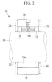
- FIG. 2 is a cross sectional view taken along the line A-A of FIG. 1 .
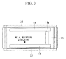
- FIG. 3 is a cross sectional view taken along the line B-B of FIG. 1 .
- the journal bearing 10 comprises a carrier ring 11, guide metals 12, a plurality of (two in this embodiment) pads 13, a plurality of (four in this embodiment) oiling nozzles (pad stops) 14, and one pad stop (stopper) 15, as main components.
- the carrier ring 11 comprises an upper half-carrier ring 16 and a lower half-carrier ring 17.
- the upper half-carrier ring 16 and the lower half-carrier ring 17 are connected via joint bolts (not shown).
- two guide metals 12 are aligned in the axial direction. As shown in FIG. 1 and FIG. 2 , these guide metals 12 are secured to the radially inside of the upper half-carrier ring 16 via bolts (not shown) so that the outer circumferential surfaces thereof can be in contact with the inner circumferential surface of the upper half-carrier ring 16. These guide metals 12 are not for supporting the load from the rotor shaft (rotation shaft) 20, but merely for preventing the leaping behavior of the rotor shaft 20.
- the pad 13 comprises an upstream pad 13a located on the backward side in the axial rotation direction of the rotor shaft 20, and a downstream pad 13b located on the forward side in the axial rotation direction of the rotor shaft 20.
- the upstream pad 13a and the downstream pad 13b are arranged side by side along the circumferential direction, and are made of, for example, W87 (white metal) or S25C.
- the upstream pad 13a and the downstream pad 13b have their outer circumferential surfaces contacted with the inner circumferential surface of the lower half-carrier ring 17, and are attached to the radially inside of the lower half-carrier ring 17 so that a predetermined space is formed (provided) between the upstream pad 13a and the downstream pad 13b.
- These pads 13a and 13b have a tilting mechanism.
- the oiling nozzles 14 are for releasing (supplying), for example, lubricating oil that has been supplied from the bottom side, to a space between the outer circumferential surface of the rotor shaft 20 (refer to FIG. 2 ) and the inner circumferential surfaces of the pads 13, and consists of: a (first) oiling nozzle 14a arranged at one ends of the guide metals 12 (the ends on the downstream side which are located on the forward side in the axial rotation direction of the rotor shaft 20); a (second) oiling nozzle 14b and a (third) oiling nozzle 14c arranged at opposite ends of the upstream pad 13a (the end on the upstream side which is located on the backward side in the axial rotation direction of the rotor shaft 20 and the end on the downstream side which is located on the forward side in the axial rotation direction of the rotor shaft 20); and a (fourth) oiling nozzle 14d arranged at one end of the downstream pad 13b (the end on the upstream side which is located on the back
- this embodiment is designed so that equal amounts of the lubricating oil can be released from the respective oiling nozzles 14a, 14b, 14c, and 14d, that is to say, so that the lubricating oil at an amount accounting for 25% of the total flowing quantity can be equally supplied from each of the oiling nozzles 14a, 14b, 14c, and 14d.
- Each of the oiling nozzles 14b, 14c, and 14d has a function as a pad stop (stopper), so that the circumferential movement of the upstream pad 13a can be restrained (limited) by the oiling nozzles 14b and 14c, and the circumferential movement of the downstream pad 13b can be restrained (limited) by the oiling nozzle 14d and the pad stop 15.
- the axial movements of the upstream pad 13a and the downstream pad 13b can be restrained (limited) by side plates 22 which are secured to opposite end faces of the lower half-carrier ring 17 via locking screws (not shown).
- the oiling nozzle is not only limited to the structure integrated with the pad stop, but also includes structures in which the oiling nozzle and the pad stop are formed as separate bodies at adjacent positions.
- the oiling nozzles 14a, 14b, 14c, and 14d for releasing lubricating oil between the outer circumferential surface of the rotor shaft 20 and the inner circumferential surfaces of the pads 13 are arranged only one ends of the guide metals 12, the opposite ends of the upstream pad 13a, and one end of the downstream pad 13b. Therefore, the number of the oiling nozzles 14a, 14b, 14c, and 14d can be reduced by half or less as compared to conventional cases. This leads to a reduction in the amount of the lubricating oil to be released between the outer circumferential surface of the rotor shaft 20 and the inner circumferential surfaces of the pads 13 (for example, 35% reduction). By so doing, the churning loss between the outer circumferential surface of the rotor shaft 20 and the inner circumferential surfaces of the pads 13 can be reduced, and the bearing loss can also be reduced.
- journal bearing 10 of this embodiment equal amounts of the lubricating oil can be released from the respective oiling nozzles 14a, 14b, 14c, and 14d.
- the configuration and the structure can be simplified, and the production cost can also be reduced.
- the present invention is not limited to the embodiment described above, but can be variously modified or changed without departing from the gist of the present invention.
- the oiling nozzle 14a may be removed (omitted) so that the lubricating oil at an amount accounting for 50% of the total flowing quantity can be supplied from the oiling nozzle 14b.
- the pad stop 15 takes a structure which supplies no oil in order to reduce the amount of the lubricating oil.
- the pad stop 15 may be provided with an oiling nozzle to be able to supply oil. By having such a structure, the pad stop 15 can also be used as a cooling sprayer which lowers the oil temperature.
Landscapes
- Engineering & Computer Science (AREA)
- General Engineering & Computer Science (AREA)
- Mechanical Engineering (AREA)
- Chemical & Material Sciences (AREA)
- Oil, Petroleum & Natural Gas (AREA)
- Physics & Mathematics (AREA)
- Fluid Mechanics (AREA)
- Sliding-Contact Bearings (AREA)
- Rolling Contact Bearings (AREA)
Abstract
Description
- The present invention relates to a journal bearing for use in rotating machines such as a steam turbine, a gas turbine, a blower, and a compressor.
- A journal bearing disclosed in Patent Citation 1 is known as an example of a journal bearing for use in rotating machines such as a steam turbine, a gas turbine, a blower, and a compressor.
-
- {PTL 1}
Japanese Unexamined Utility Model Application, Publication No.Sho 63-132114 - Recently, a journal bearing has been proposed in which a plurality of (for example, four) pads are arranged radially inside a carrier ring along the circumferential direction (more specifically, a plurality of (for example, two) pads are arranged radially inside an upper half of the carrier ring (upper half of the mainframe) along the circumferential direction, and a plurality of (for example, two) pads are arranged radially inside a lower half of the carrier ring (lower half of the mainframe) along the circumferential direction), while a total of eight oiling nozzles are arranged by having each one of these nozzles arranged at every opposite end of the respective pads.
However, in such a journal bearing, since lubricating oil is released (supplied) from the oiling nozzles attached to the upper half of the carrier ring which does not receive any load (which is not loaded), the oil is prone to be oversupplied. This leads to a problem of an increase in the churning loss between the outer circumferential surface of the rotor shaft (rotation shaft) and the inner circumferential surfaces of the pads, causing an increase in the bearing loss. - The present invention was made to address such a situation, with an object of providing a journal bearing capable of reducing the amount of the lubricating oil released (supplied) between the outer circumferential surface of the rotation shaft and the inner circumferential surfaces of the pads, so as to reduce the churning loss between the outer circumferential surface of the rotation shaft and the inner circumferential surfaces of the pads, and to reduce the bearing loss.
- In order to achieve the above object, the present invention employs the following solutions.
The journal bearing according to the present invention is a journal bearing which rotatably supports a rotation shaft, and which comprises: a carrier ring including an upper half-carrier ring and a lower half-carrier ring; a plurality of pads arranged radially inside the lower half-carrier ring at intervals, for receiving load from the rotation shaft; and a plurality of pad stops respectively arranged at the circumferentially opposite ends of the respective pads, for restraining circumferential movements of the respective pads, wherein, among these pad stops, the pad stops other than the pad stop located in the most forward position in the axial rotation direction of the rotation shaft have functions as oiling nozzles for releasing lubricating oil between the outer circumferential surface of the rotation shaft and the inner circumferential surfaces of the pads. - According to the journal bearing of the present invention, the number of the pad stops which have functions as oiling nozzles for releasing lubricating oil between the outer circumferential surface of the rotation shaft and the inner circumferential surfaces of the pads can be reduced by half or less as compared to conventional cases. This leads to a reduction in the amount of the lubricating oil to be released (supplied) between the outer circumferential surface of the rotation shaft and the inner circumferential surfaces of the pads (for example, 35% reduction).
By so doing, the churning loss between the outer circumferential surface of the rotation shaft and the inner circumferential surfaces of the pads can be reduced, and the bearing loss can also be reduced. - The above-mentioned journal bearing is more preferably configured such that equal amounts of the lubricating oil can be released from the respective pad stops having functions as oiling nozzles.
- According to such a journal bearing, there is no need of adjusting (setting) the amount of oil for each one of the pad stops (oiling nozzles). Therefore, the configuration and the structure can be simplified, and the production cost can also be reduced.
- The above-mentioned journal bearing is more preferably configured such that the pad stop located in the most forward position in the axial rotation direction of the rotation shaft releases a smaller amount of the lubricating oil than the oil amount released from any one of the other pad stops, so as to cool down the lubricating oil within the bearing.
- According to such a journal bearing, while reducing the amount of lubricating oil to be supplied as a whole, the oil temperature can be kept low and the bearing can be kept sound.
- The rotating machine according to the present invention comprises a journal bearing capable of reducing the amount of lubricating oil to be released (supplied) between the outer circumferential surface of the rotation shaft and the inner circumferential surfaces of the pads (for example, 35% reduction).
- According to the rotating machine of the present invention, when the rotating machine is horizontally placed so that the bearing load can work downward only, the churning loss between the outer circumferential surface of the rotation shaft and the inner circumferential surfaces of the pads can be reduced, and the bearing loss can also be reduced.
- The present invention can offer an effect of reducing the amount of lubricating oil released (supplied) between the outer circumferential surface of the rotation shaft and the inner circumferential surfaces of the pads, so as to reduce the churning loss between the outer circumferential surface of the rotation shaft and the inner circumferential surfaces of the pads, and to reduce the bearing loss.
-
- {
FIG. 1 }
FIG. 1 is a front view of a journal bearing according to one embodiment of the present invention. - {
FIG. 2 }
FIG. 2 is a cross sectional view taken along the line A-A ofFIG. 1 . - {
FIG. 3 }
FIG. 3 is a cross sectional view taken along the line B-B ofFIG. 1 . - Hereunder is a description of one embodiment of a journal bearing according to the present invention, with reference to
FIG. 1 through FIG. 3 .
FIG. 1 is a front view of the journal bearing according to this embodiment.FIG. 2 is a cross sectional view taken along the line A-A ofFIG. 1 .FIG. 3 is a cross sectional view taken along the line B-B ofFIG. 1 . - As shown in
FIG. 1 , the journal bearing 10 comprises acarrier ring 11,guide metals 12, a plurality of (two in this embodiment)pads 13, a plurality of (four in this embodiment) oiling nozzles (pad stops) 14, and one pad stop (stopper) 15, as main components.
Thecarrier ring 11 comprises an upper half-carrier ring 16 and a lower half-carrier ring 17. The upper half-carrier ring 16 and the lower half-carrier ring 17 are connected via joint bolts (not shown). - As shown in
FIG. 2 , twoguide metals 12 are aligned in the axial direction. As shown inFIG. 1 andFIG. 2 , theseguide metals 12 are secured to the radially inside of the upper half-carrier ring 16 via bolts (not shown) so that the outer circumferential surfaces thereof can be in contact with the inner circumferential surface of the upper half-carrier ring 16. Theseguide metals 12 are not for supporting the load from the rotor shaft (rotation shaft) 20, but merely for preventing the leaping behavior of therotor shaft 20. - As shown in
FIG. 1 , thepad 13 comprises anupstream pad 13a located on the backward side in the axial rotation direction of therotor shaft 20, and adownstream pad 13b located on the forward side in the axial rotation direction of therotor shaft 20. Theupstream pad 13a and thedownstream pad 13b are arranged side by side along the circumferential direction, and are made of, for example, W87 (white metal) or S25C. In addition, theupstream pad 13a and thedownstream pad 13b have their outer circumferential surfaces contacted with the inner circumferential surface of the lower half-carrier ring 17, and are attached to the radially inside of the lower half-carrier ring 17 so that a predetermined space is formed (provided) between theupstream pad 13a and thedownstream pad 13b. Thesepads - The
oiling nozzles 14 are for releasing (supplying), for example, lubricating oil that has been supplied from the bottom side, to a space between the outer circumferential surface of the rotor shaft 20 (refer toFIG. 2 ) and the inner circumferential surfaces of thepads 13, and consists of: a (first) oilingnozzle 14a arranged at one ends of the guide metals 12 (the ends on the downstream side which are located on the forward side in the axial rotation direction of the rotor shaft 20); a (second)oiling nozzle 14b and a (third)oiling nozzle 14c arranged at opposite ends of theupstream pad 13a (the end on the upstream side which is located on the backward side in the axial rotation direction of therotor shaft 20 and the end on the downstream side which is located on the forward side in the axial rotation direction of the rotor shaft 20); and a (fourth) oilingnozzle 14d arranged at one end of thedownstream pad 13b (the end on the upstream side which is located on the backward side in the axial rotation direction of the rotor shaft 20). Moreover, this embodiment is designed so that equal amounts of the lubricating oil can be released from therespective oiling nozzles oiling nozzles - Each of the
oiling nozzles upstream pad 13a can be restrained (limited) by theoiling nozzles downstream pad 13b can be restrained (limited) by theoiling nozzle 14d and the pad stop 15.
In addition, the axial movements of theupstream pad 13a and thedownstream pad 13b can be restrained (limited) byside plates 22 which are secured to opposite end faces of the lower half-carrier ring 17 via locking screws (not shown).
The oiling nozzle is not only limited to the structure integrated with the pad stop, but also includes structures in which the oiling nozzle and the pad stop are formed as separate bodies at adjacent positions. - According to the journal bearing 10 of this embodiment, the
oiling nozzles rotor shaft 20 and the inner circumferential surfaces of thepads 13 are arranged only one ends of theguide metals 12, the opposite ends of theupstream pad 13a, and one end of thedownstream pad 13b. Therefore, the number of theoiling nozzles rotor shaft 20 and the inner circumferential surfaces of the pads 13 (for example, 35% reduction).
By so doing, the churning loss between the outer circumferential surface of therotor shaft 20 and the inner circumferential surfaces of thepads 13 can be reduced, and the bearing loss can also be reduced. - In addition, according to the journal bearing 10 of this embodiment, equal amounts of the lubricating oil can be released from the
respective oiling nozzles
By so doing, there is no need of adjusting (setting) the amount of oil for each one of theoiling nozzles - The present invention is not limited to the embodiment described above, but can be variously modified or changed without departing from the gist of the present invention.
For example, theoiling nozzle 14a may be removed (omitted) so that the lubricating oil at an amount accounting for 50% of the total flowing quantity can be supplied from theoiling nozzle 14b.
Moreover, thepad stop 15 takes a structure which supplies no oil in order to reduce the amount of the lubricating oil. However, thepad stop 15 may be provided with an oiling nozzle to be able to supply oil. By having such a structure, thepad stop 15 can also be used as a cooling sprayer which lowers the oil temperature. -
- 10:
- Journal bearing
- 11:
- Carrier ring
- 13:
- Pad
- 13a:
- Upstream pad (pad)
- 13b:
- Downstream pad (pad)
- 14:
- Oiling nozzle (pad stop)
- 14a:
- Oiling nozzle (pad stop)
- 14b:
- Oiling nozzle (pad stop)
- 14c:
- Oiling nozzle (pad stop)
- 14d:
- Oiling nozzle (pad stop)
- 15:
- Pad stop
- 16:
- Upper half-carrier ring
- 17:
- Lower half-carrier ring
- 20:
- Rotor shaft (rotation shaft)
Claims (4)
- A journal bearing which rotatably supports a rotation shaft, and which comprises:a carrier ring including an upper half-carrier ring and a lower half-carrier ring; a plurality of pads arranged radially inside the lower half-carrier ring at intervals, for receiving load from the rotation shaft; and a plurality of pad stops respectively arranged at the circumferentially opposite ends of the respective pads, for restraining circumferential movements of the respective pads, wherein,among these pad stops, the pad stops other than the pad stop located in the most forward position in the axial rotation direction of the rotation shaft have functions as oiling nozzles for releasing lubricating oil between the outer circumferential surface of the rotation shaft and the inner circumferential surfaces of the pads.
- A journal bearing according to claim 1, wherein equal amounts of the lubricating oil can be released from the respective pad stops having functions as oiling nozzles.
- A journal bearing according to either one of claim 1 and claim 2, wherein the pad stop located in the most forward position in the axial rotation direction of the rotation shaft releases a smaller amount of the lubricating oil than the oil amount released from any one of the other pad stops, so as to cool down the lubricating oil within the bearing.
- A rotating machine comprising the journal bearing according to any one of claim 1 through claim 3.
Applications Claiming Priority (2)
| Application Number | Priority Date | Filing Date | Title |
|---|---|---|---|
| JP2009047355A JP4764486B2 (en) | 2009-02-27 | 2009-02-27 | Journal bearing |
| PCT/JP2009/069326 WO2010097990A1 (en) | 2009-02-27 | 2009-11-13 | Journal bearing |
Publications (3)
| Publication Number | Publication Date |
|---|---|
| EP2402621A1 true EP2402621A1 (en) | 2012-01-04 |
| EP2402621A4 EP2402621A4 (en) | 2012-07-18 |
| EP2402621B1 EP2402621B1 (en) | 2016-09-21 |
Family
ID=42665211
Family Applications (1)
| Application Number | Title | Priority Date | Filing Date |
|---|---|---|---|
| EP09840837.0A Active EP2402621B1 (en) | 2009-02-27 | 2009-11-13 | Journal bearing |
Country Status (6)
| Country | Link |
|---|---|
| US (1) | US8123409B2 (en) |
| EP (1) | EP2402621B1 (en) |
| JP (1) | JP4764486B2 (en) |
| KR (1) | KR101088271B1 (en) |
| CN (1) | CN102149931B (en) |
| WO (1) | WO2010097990A1 (en) |
Cited By (3)
| Publication number | Priority date | Publication date | Assignee | Title |
|---|---|---|---|---|
| EP3228883A4 (en) * | 2014-12-01 | 2018-05-30 | Mitsubishi Electric Corporation | Journal bearing |
| US10962051B2 (en) | 2017-02-23 | 2021-03-30 | Mitsubishi Power, Ltd. | Bearing device and rotary machine |
| US11143242B2 (en) | 2016-02-29 | 2021-10-12 | Mitsubishi Power, Ltd. | Journal Device and rotary machine |
Families Citing this family (25)
| Publication number | Priority date | Publication date | Assignee | Title |
|---|---|---|---|---|
| EP2345820B1 (en) * | 2008-11-12 | 2017-11-01 | Mitsubishi Heavy Industries, Ltd. | Rotation structure with journal bearing and method of assembling same |
| WO2013043495A1 (en) | 2011-09-21 | 2013-03-28 | Dresser-Rand Company | Tilt pad bearing with through-pivot lubrication |
| JP6037916B2 (en) | 2013-03-29 | 2016-12-07 | 三菱日立パワーシステムズ株式会社 | Rotating shaft support structure and rotating machine |
| CN107002750B (en) * | 2014-11-28 | 2019-06-07 | 三菱日立电力系统株式会社 | The bearing of journals, rotating machinery |
| CN104533955B (en) * | 2015-01-13 | 2017-01-25 | 江南大学 | A water-lubricated tilting pad hydrostatic bearing structure cooled by return water tank |
| JP5936725B1 (en) * | 2015-01-30 | 2016-06-22 | 三菱日立パワーシステムズ株式会社 | Journal bearing device and rotating machine |
| JP2016142311A (en) * | 2015-01-30 | 2016-08-08 | 三菱日立パワーシステムズ株式会社 | Turbine |
| JP6403593B2 (en) * | 2015-02-06 | 2018-10-10 | 三菱日立パワーシステムズ株式会社 | Journal bearing and rotating machine |
| JP6403594B2 (en) * | 2015-02-06 | 2018-10-10 | 三菱日立パワーシステムズ株式会社 | Journal bearing and rotating machine |
| JP6460818B2 (en) * | 2015-02-06 | 2019-01-30 | 三菱日立パワーシステムズ株式会社 | Bearing device and rotating machine |
| JP6440516B2 (en) * | 2015-02-06 | 2018-12-19 | 三菱日立パワーシステムズ株式会社 | Bearing device and rotating machine |
| JP6437838B2 (en) * | 2015-02-06 | 2018-12-12 | 三菱日立パワーシステムズ株式会社 | Journal bearing and rotating machine |
| JP6920026B2 (en) * | 2016-02-29 | 2021-08-18 | 三菱パワー株式会社 | Journal bearings and rotating machinery |
| JP6571026B2 (en) | 2016-02-29 | 2019-09-04 | 三菱日立パワーシステムズ株式会社 | Journal bearing and rotating machine |
| JP6849310B2 (en) | 2016-02-29 | 2021-03-24 | 三菱パワー株式会社 | Journal bearings and rotating machinery |
| DE112016006525T5 (en) | 2016-08-10 | 2018-11-22 | Mitsubishi Hitachi Power Systems, Ltd. | Slide bearing device and rotary machine |
| KR102058810B1 (en) * | 2016-08-10 | 2019-12-23 | 미츠비시 히타치 파워 시스템즈 가부시키가이샤 | Bearing device and rolling machine |
| KR102116058B1 (en) | 2016-08-10 | 2020-05-28 | 미츠비시 히타치 파워 시스템즈 가부시키가이샤 | Bearing device and rotating machine |
| WO2018029837A1 (en) * | 2016-08-10 | 2018-02-15 | 三菱日立パワーシステムズ株式会社 | Journal bearing and rotary machine |
| JP6899235B2 (en) | 2017-03-24 | 2021-07-07 | 三菱重工業株式会社 | Bearing pads for tilting pad bearings, tilting pad bearings and rotating machinery |
| WO2018187787A1 (en) | 2017-04-06 | 2018-10-11 | Waukesha Bearings Coporation | Improved efficiency journal bearing |
| JP6979332B2 (en) | 2017-10-31 | 2021-12-15 | 三菱パワー株式会社 | Tilting pad bearing |
| JP6745292B2 (en) * | 2018-03-09 | 2020-08-26 | 三菱重工業株式会社 | Pad bearings, rotating machinery |
| KR102582879B1 (en) * | 2018-12-28 | 2023-09-25 | 미츠비시 파워 가부시키가이샤 | Bearing units, rotating machines, and nozzles |
| WO2022157850A1 (en) * | 2021-01-20 | 2022-07-28 | 三菱電機株式会社 | Journal bearing and rotating machine |
Family Cites Families (20)
| Publication number | Priority date | Publication date | Assignee | Title |
|---|---|---|---|---|
| GB376153A (en) * | 1930-11-14 | 1932-07-07 | Nomy Ab | Improvements in bearings |
| US3549215A (en) * | 1968-10-21 | 1970-12-22 | Pioneer Motor Bearing Co | Hydrostatically supported tilting pad journal bearing |
| GB1397551A (en) * | 1971-06-24 | 1975-06-11 | Glacier Metal Co Ltd | Journal bearings |
| US4097094A (en) * | 1976-08-24 | 1978-06-27 | Waukesha Bearings Corporation | Journal bearing assembly with flexible support and viscous damping |
| US4597676A (en) * | 1984-04-30 | 1986-07-01 | General Electric Company | Hybrid bearing |
| US4686403A (en) | 1986-11-07 | 1987-08-11 | Westinghouse Electric Corp. | Dynamoelectric machine with rockable bearing supports |
| JPS63132114U (en) | 1987-02-20 | 1988-08-30 | ||
| JPS63132114A (en) | 1987-10-24 | 1988-06-04 | Res Inst Electric Magnetic Alloys | Manufacturing method of eddy current sensor |
| EP0408812B1 (en) | 1989-07-21 | 2000-03-01 | Hewlett-Packard Company | Distributed object based systems |
| JPH0362223A (en) | 1989-07-31 | 1991-03-18 | Toshiba Corp | Local stack control method for prolog |
| JPH05332355A (en) | 1992-06-01 | 1993-12-14 | Mitsubishi Heavy Ind Ltd | Tilting pad type journal bearing |
| GB2292192B (en) * | 1994-08-06 | 1997-12-10 | Glacier Metal Co Ltd | Journal bearings |
| JPH09133127A (en) * | 1995-11-09 | 1997-05-20 | Toshiba Corp | Pad type journal bearing |
| EP0789151B1 (en) * | 1996-02-06 | 2000-05-10 | Flender Graffenstaden | Hydrodynamic bearing comprising a fixed sliding surface and tiltable sliding pads |
| EP0791760A3 (en) * | 1996-02-20 | 1997-09-10 | Ebara Corporation | Water lubricated bearing or water lubricated seal |
| JPH11182535A (en) * | 1997-12-18 | 1999-07-06 | Daido Metal Co Ltd | Tilting pad journal bearing |
| JP2000274432A (en) * | 1999-03-19 | 2000-10-03 | Toshiba Corp | Pad type journal bearing |
| JP2001165152A (en) * | 1999-12-10 | 2001-06-19 | Mitsubishi Heavy Ind Ltd | Bearing device |
| US20060093246A1 (en) * | 2003-08-25 | 2006-05-04 | Hideki Akita | Sliding bearing assembly and sliding bearing |
| JP4675643B2 (en) * | 2005-02-28 | 2011-04-27 | 株式会社東芝 | Journal bearing |
-
2009
- 2009-02-27 JP JP2009047355A patent/JP4764486B2/en active Active
- 2009-11-13 CN CN2009801352819A patent/CN102149931B/en active Active
- 2009-11-13 EP EP09840837.0A patent/EP2402621B1/en active Active
- 2009-11-13 KR KR1020117018367A patent/KR101088271B1/en active Active
- 2009-11-13 WO PCT/JP2009/069326 patent/WO2010097990A1/en not_active Ceased
- 2009-11-23 US US12/623,704 patent/US8123409B2/en active Active
Cited By (3)
| Publication number | Priority date | Publication date | Assignee | Title |
|---|---|---|---|---|
| EP3228883A4 (en) * | 2014-12-01 | 2018-05-30 | Mitsubishi Electric Corporation | Journal bearing |
| US11143242B2 (en) | 2016-02-29 | 2021-10-12 | Mitsubishi Power, Ltd. | Journal Device and rotary machine |
| US10962051B2 (en) | 2017-02-23 | 2021-03-30 | Mitsubishi Power, Ltd. | Bearing device and rotary machine |
Also Published As
| Publication number | Publication date |
|---|---|
| WO2010097990A1 (en) | 2010-09-02 |
| EP2402621B1 (en) | 2016-09-21 |
| US20100220944A1 (en) | 2010-09-02 |
| CN102149931A (en) | 2011-08-10 |
| KR101088271B1 (en) | 2011-11-30 |
| JP2010203481A (en) | 2010-09-16 |
| JP4764486B2 (en) | 2011-09-07 |
| US8123409B2 (en) | 2012-02-28 |
| EP2402621A4 (en) | 2012-07-18 |
| KR20110095428A (en) | 2011-08-24 |
| CN102149931B (en) | 2013-11-06 |
Similar Documents
| Publication | Publication Date | Title |
|---|---|---|
| EP2402621B1 (en) | Journal bearing | |
| DK2951451T3 (en) | SLIDING BEARING KIT | |
| CN103842674B (en) | The bearing of dynamically lubricating and the method for dynamically lubricating bearing | |
| CN103470319B (en) | For the journal shaft rim of turbine | |
| US20120237149A1 (en) | Bearing structure of turbocharger | |
| EP3460271B1 (en) | Fluid film bearing for a wind turbine | |
| JP2012117608A (en) | Thrust bearing device | |
| KR102665432B1 (en) | Eccentrically swinging reducer device and Method for supplying lubricant | |
| US8066472B2 (en) | Method and apparatus for fan shaft bearing lubrication | |
| JP4502841B2 (en) | Turbomachine with small roller bearings | |
| EP2746603A1 (en) | Journal bearing device | |
| DE112016003110T5 (en) | Bearing assembly and turbocharger | |
| US10508565B2 (en) | Journal bearing and rotary machine | |
| JP2013217436A (en) | Rolling bearing device for turbocharger | |
| EP3851690B1 (en) | Damper bearing and damper | |
| US20170328236A1 (en) | Oil discharging structure for bearing | |
| US10451105B2 (en) | Journal bearing and rotary machine | |
| JP6223600B2 (en) | Journal bearing | |
| JP2014051898A (en) | Supercharger | |
| CN203230740U (en) | Rolling bearing device provided with lubricating agent supply mechanism | |
| US10738822B2 (en) | Journal device and rotary machine | |
| JP5169954B2 (en) | Tilting pad bearing | |
| EP3690270A1 (en) | Ball bearing and main shaft device for machine tool | |
| JP2025086175A (en) | Angular contact ball bearing |
Legal Events
| Date | Code | Title | Description |
|---|---|---|---|
| PUAI | Public reference made under article 153(3) epc to a published international application that has entered the european phase |
Free format text: ORIGINAL CODE: 0009012 |
|
| 17P | Request for examination filed |
Effective date: 20110224 |
|
| AK | Designated contracting states |
Kind code of ref document: A1 Designated state(s): AT BE BG CH CY CZ DE DK EE ES FI FR GB GR HR HU IE IS IT LI LT LU LV MC MK MT NL NO PL PT RO SE SI SK SM TR |
|
| DAX | Request for extension of the european patent (deleted) | ||
| A4 | Supplementary search report drawn up and despatched |
Effective date: 20120614 |
|
| RIC1 | Information provided on ipc code assigned before grant |
Ipc: F16C 33/08 20060101ALI20120608BHEP Ipc: F16C 17/03 20060101AFI20120608BHEP Ipc: F16C 33/10 20060101ALI20120608BHEP |
|
| RAP1 | Party data changed (applicant data changed or rights of an application transferred) |
Owner name: MITSUBISHI HITACHI POWER SYSTEMS, LTD. |
|
| 17Q | First examination report despatched |
Effective date: 20150630 |
|
| REG | Reference to a national code |
Ref country code: DE Ref legal event code: R079 Ref document number: 602009041333 Country of ref document: DE Free format text: PREVIOUS MAIN CLASS: F16C0017030000 Ipc: F16C0033100000 |
|
| RIC1 | Information provided on ipc code assigned before grant |
Ipc: F16C 33/10 20060101AFI20160302BHEP Ipc: F16C 32/06 20060101ALN20160302BHEP |
|
| GRAP | Despatch of communication of intention to grant a patent |
Free format text: ORIGINAL CODE: EPIDOSNIGR1 |
|
| INTG | Intention to grant announced |
Effective date: 20160420 |
|
| GRAS | Grant fee paid |
Free format text: ORIGINAL CODE: EPIDOSNIGR3 |
|
| GRAA | (expected) grant |
Free format text: ORIGINAL CODE: 0009210 |
|
| AK | Designated contracting states |
Kind code of ref document: B1 Designated state(s): AT BE BG CH CY CZ DE DK EE ES FI FR GB GR HR HU IE IS IT LI LT LU LV MC MK MT NL NO PL PT RO SE SI SK SM TR |
|
| REG | Reference to a national code |
Ref country code: GB Ref legal event code: FG4D |
|
| REG | Reference to a national code |
Ref country code: CH Ref legal event code: EP |
|
| REG | Reference to a national code |
Ref country code: AT Ref legal event code: REF Ref document number: 831309 Country of ref document: AT Kind code of ref document: T Effective date: 20161015 |
|
| REG | Reference to a national code |
Ref country code: IE Ref legal event code: FG4D |
|
| REG | Reference to a national code |
Ref country code: DE Ref legal event code: R096 Ref document number: 602009041333 Country of ref document: DE |
|
| REG | Reference to a national code |
Ref country code: LT Ref legal event code: MG4D Ref country code: NL Ref legal event code: MP Effective date: 20160921 |
|
| PG25 | Lapsed in a contracting state [announced via postgrant information from national office to epo] |
Ref country code: LT Free format text: LAPSE BECAUSE OF FAILURE TO SUBMIT A TRANSLATION OF THE DESCRIPTION OR TO PAY THE FEE WITHIN THE PRESCRIBED TIME-LIMIT Effective date: 20160921 Ref country code: FI Free format text: LAPSE BECAUSE OF FAILURE TO SUBMIT A TRANSLATION OF THE DESCRIPTION OR TO PAY THE FEE WITHIN THE PRESCRIBED TIME-LIMIT Effective date: 20160921 Ref country code: NO Free format text: LAPSE BECAUSE OF FAILURE TO SUBMIT A TRANSLATION OF THE DESCRIPTION OR TO PAY THE FEE WITHIN THE PRESCRIBED TIME-LIMIT Effective date: 20161221 |
|
| REG | Reference to a national code |
Ref country code: AT Ref legal event code: MK05 Ref document number: 831309 Country of ref document: AT Kind code of ref document: T Effective date: 20160921 |
|
| PG25 | Lapsed in a contracting state [announced via postgrant information from national office to epo] |
Ref country code: GR Free format text: LAPSE BECAUSE OF FAILURE TO SUBMIT A TRANSLATION OF THE DESCRIPTION OR TO PAY THE FEE WITHIN THE PRESCRIBED TIME-LIMIT Effective date: 20161222 Ref country code: BE Free format text: LAPSE BECAUSE OF NON-PAYMENT OF DUE FEES Effective date: 20161130 Ref country code: LV Free format text: LAPSE BECAUSE OF FAILURE TO SUBMIT A TRANSLATION OF THE DESCRIPTION OR TO PAY THE FEE WITHIN THE PRESCRIBED TIME-LIMIT Effective date: 20160921 Ref country code: SE Free format text: LAPSE BECAUSE OF FAILURE TO SUBMIT A TRANSLATION OF THE DESCRIPTION OR TO PAY THE FEE WITHIN THE PRESCRIBED TIME-LIMIT Effective date: 20160921 Ref country code: NL Free format text: LAPSE BECAUSE OF FAILURE TO SUBMIT A TRANSLATION OF THE DESCRIPTION OR TO PAY THE FEE WITHIN THE PRESCRIBED TIME-LIMIT Effective date: 20160921 |
|
| PG25 | Lapsed in a contracting state [announced via postgrant information from national office to epo] |
Ref country code: EE Free format text: LAPSE BECAUSE OF FAILURE TO SUBMIT A TRANSLATION OF THE DESCRIPTION OR TO PAY THE FEE WITHIN THE PRESCRIBED TIME-LIMIT Effective date: 20160921 Ref country code: RO Free format text: LAPSE BECAUSE OF FAILURE TO SUBMIT A TRANSLATION OF THE DESCRIPTION OR TO PAY THE FEE WITHIN THE PRESCRIBED TIME-LIMIT Effective date: 20160921 |
|
| PG25 | Lapsed in a contracting state [announced via postgrant information from national office to epo] |
Ref country code: BE Free format text: LAPSE BECAUSE OF FAILURE TO SUBMIT A TRANSLATION OF THE DESCRIPTION OR TO PAY THE FEE WITHIN THE PRESCRIBED TIME-LIMIT Effective date: 20160921 Ref country code: PT Free format text: LAPSE BECAUSE OF FAILURE TO SUBMIT A TRANSLATION OF THE DESCRIPTION OR TO PAY THE FEE WITHIN THE PRESCRIBED TIME-LIMIT Effective date: 20170123 Ref country code: IS Free format text: LAPSE BECAUSE OF FAILURE TO SUBMIT A TRANSLATION OF THE DESCRIPTION OR TO PAY THE FEE WITHIN THE PRESCRIBED TIME-LIMIT Effective date: 20170121 Ref country code: SM Free format text: LAPSE BECAUSE OF FAILURE TO SUBMIT A TRANSLATION OF THE DESCRIPTION OR TO PAY THE FEE WITHIN THE PRESCRIBED TIME-LIMIT Effective date: 20160921 Ref country code: PL Free format text: LAPSE BECAUSE OF FAILURE TO SUBMIT A TRANSLATION OF THE DESCRIPTION OR TO PAY THE FEE WITHIN THE PRESCRIBED TIME-LIMIT Effective date: 20160921 Ref country code: ES Free format text: LAPSE BECAUSE OF FAILURE TO SUBMIT A TRANSLATION OF THE DESCRIPTION OR TO PAY THE FEE WITHIN THE PRESCRIBED TIME-LIMIT Effective date: 20160921 Ref country code: SK Free format text: LAPSE BECAUSE OF FAILURE TO SUBMIT A TRANSLATION OF THE DESCRIPTION OR TO PAY THE FEE WITHIN THE PRESCRIBED TIME-LIMIT Effective date: 20160921 Ref country code: AT Free format text: LAPSE BECAUSE OF FAILURE TO SUBMIT A TRANSLATION OF THE DESCRIPTION OR TO PAY THE FEE WITHIN THE PRESCRIBED TIME-LIMIT Effective date: 20160921 Ref country code: BG Free format text: LAPSE BECAUSE OF FAILURE TO SUBMIT A TRANSLATION OF THE DESCRIPTION OR TO PAY THE FEE WITHIN THE PRESCRIBED TIME-LIMIT Effective date: 20161221 Ref country code: CZ Free format text: LAPSE BECAUSE OF FAILURE TO SUBMIT A TRANSLATION OF THE DESCRIPTION OR TO PAY THE FEE WITHIN THE PRESCRIBED TIME-LIMIT Effective date: 20160921 |
|
| REG | Reference to a national code |
Ref country code: DE Ref legal event code: R097 Ref document number: 602009041333 Country of ref document: DE |
|
| PG25 | Lapsed in a contracting state [announced via postgrant information from national office to epo] |
Ref country code: IT Free format text: LAPSE BECAUSE OF FAILURE TO SUBMIT A TRANSLATION OF THE DESCRIPTION OR TO PAY THE FEE WITHIN THE PRESCRIBED TIME-LIMIT Effective date: 20160921 |
|
| REG | Reference to a national code |
Ref country code: CH Ref legal event code: PL |
|
| PLBE | No opposition filed within time limit |
Free format text: ORIGINAL CODE: 0009261 |
|
| STAA | Information on the status of an ep patent application or granted ep patent |
Free format text: STATUS: NO OPPOSITION FILED WITHIN TIME LIMIT |
|
| PG25 | Lapsed in a contracting state [announced via postgrant information from national office to epo] |
Ref country code: LI Free format text: LAPSE BECAUSE OF NON-PAYMENT OF DUE FEES Effective date: 20161130 Ref country code: DK Free format text: LAPSE BECAUSE OF FAILURE TO SUBMIT A TRANSLATION OF THE DESCRIPTION OR TO PAY THE FEE WITHIN THE PRESCRIBED TIME-LIMIT Effective date: 20160921 Ref country code: CH Free format text: LAPSE BECAUSE OF NON-PAYMENT OF DUE FEES Effective date: 20161130 |
|
| GBPC | Gb: european patent ceased through non-payment of renewal fee |
Effective date: 20161221 |
|
| REG | Reference to a national code |
Ref country code: IE Ref legal event code: MM4A |
|
| REG | Reference to a national code |
Ref country code: FR Ref legal event code: ST Effective date: 20170731 |
|
| 26N | No opposition filed |
Effective date: 20170622 |
|
| PG25 | Lapsed in a contracting state [announced via postgrant information from national office to epo] |
Ref country code: LU Free format text: LAPSE BECAUSE OF NON-PAYMENT OF DUE FEES Effective date: 20161130 |
|
| PG25 | Lapsed in a contracting state [announced via postgrant information from national office to epo] |
Ref country code: FR Free format text: LAPSE BECAUSE OF NON-PAYMENT OF DUE FEES Effective date: 20161130 |
|
| PG25 | Lapsed in a contracting state [announced via postgrant information from national office to epo] |
Ref country code: GB Free format text: LAPSE BECAUSE OF NON-PAYMENT OF DUE FEES Effective date: 20161221 Ref country code: SI Free format text: LAPSE BECAUSE OF FAILURE TO SUBMIT A TRANSLATION OF THE DESCRIPTION OR TO PAY THE FEE WITHIN THE PRESCRIBED TIME-LIMIT Effective date: 20160921 Ref country code: IE Free format text: LAPSE BECAUSE OF NON-PAYMENT OF DUE FEES Effective date: 20161113 |
|
| PG25 | Lapsed in a contracting state [announced via postgrant information from national office to epo] |
Ref country code: HU Free format text: LAPSE BECAUSE OF FAILURE TO SUBMIT A TRANSLATION OF THE DESCRIPTION OR TO PAY THE FEE WITHIN THE PRESCRIBED TIME-LIMIT; INVALID AB INITIO Effective date: 20091113 Ref country code: CY Free format text: LAPSE BECAUSE OF FAILURE TO SUBMIT A TRANSLATION OF THE DESCRIPTION OR TO PAY THE FEE WITHIN THE PRESCRIBED TIME-LIMIT Effective date: 20160921 |
|
| PG25 | Lapsed in a contracting state [announced via postgrant information from national office to epo] |
Ref country code: TR Free format text: LAPSE BECAUSE OF FAILURE TO SUBMIT A TRANSLATION OF THE DESCRIPTION OR TO PAY THE FEE WITHIN THE PRESCRIBED TIME-LIMIT Effective date: 20160921 Ref country code: MK Free format text: LAPSE BECAUSE OF FAILURE TO SUBMIT A TRANSLATION OF THE DESCRIPTION OR TO PAY THE FEE WITHIN THE PRESCRIBED TIME-LIMIT Effective date: 20160921 Ref country code: MC Free format text: LAPSE BECAUSE OF FAILURE TO SUBMIT A TRANSLATION OF THE DESCRIPTION OR TO PAY THE FEE WITHIN THE PRESCRIBED TIME-LIMIT Effective date: 20160921 Ref country code: HR Free format text: LAPSE BECAUSE OF FAILURE TO SUBMIT A TRANSLATION OF THE DESCRIPTION OR TO PAY THE FEE WITHIN THE PRESCRIBED TIME-LIMIT Effective date: 20160921 |
|
| PG25 | Lapsed in a contracting state [announced via postgrant information from national office to epo] |
Ref country code: MT Free format text: LAPSE BECAUSE OF NON-PAYMENT OF DUE FEES Effective date: 20161113 |
|
| PGFP | Annual fee paid to national office [announced via postgrant information from national office to epo] |
Ref country code: DE Payment date: 20250930 Year of fee payment: 17 |