EP2402613A1 - Pompe à vide de type sèche - Google Patents
Pompe à vide de type sèche Download PDFInfo
- Publication number
- EP2402613A1 EP2402613A1 EP20110171594 EP11171594A EP2402613A1 EP 2402613 A1 EP2402613 A1 EP 2402613A1 EP 20110171594 EP20110171594 EP 20110171594 EP 11171594 A EP11171594 A EP 11171594A EP 2402613 A1 EP2402613 A1 EP 2402613A1
- Authority
- EP
- European Patent Office
- Prior art keywords
- lubricant
- reservoir
- vacuum pump
- return channel
- baffle
- Prior art date
- Legal status (The legal status is an assumption and is not a legal conclusion. Google has not performed a legal analysis and makes no representation as to the accuracy of the status listed.)
- Granted
Links
Images

Classifications
-
- F—MECHANICAL ENGINEERING; LIGHTING; HEATING; WEAPONS; BLASTING
- F04—POSITIVE - DISPLACEMENT MACHINES FOR LIQUIDS; PUMPS FOR LIQUIDS OR ELASTIC FLUIDS
- F04C—ROTARY-PISTON, OR OSCILLATING-PISTON, POSITIVE-DISPLACEMENT MACHINES FOR LIQUIDS; ROTARY-PISTON, OR OSCILLATING-PISTON, POSITIVE-DISPLACEMENT PUMPS
- F04C29/00—Component parts, details or accessories of pumps or pumping installations, not provided for in groups F04C18/00 - F04C28/00
- F04C29/02—Lubrication; Lubricant separation
-
- F—MECHANICAL ENGINEERING; LIGHTING; HEATING; WEAPONS; BLASTING
- F01—MACHINES OR ENGINES IN GENERAL; ENGINE PLANTS IN GENERAL; STEAM ENGINES
- F01C—ROTARY-PISTON OR OSCILLATING-PISTON MACHINES OR ENGINES
- F01C19/00—Sealing arrangements in rotary-piston machines or engines
- F01C19/005—Structure and composition of sealing elements such as sealing strips, sealing rings and the like; Coating of these elements
-
- F—MECHANICAL ENGINEERING; LIGHTING; HEATING; WEAPONS; BLASTING
- F04—POSITIVE - DISPLACEMENT MACHINES FOR LIQUIDS; PUMPS FOR LIQUIDS OR ELASTIC FLUIDS
- F04C—ROTARY-PISTON, OR OSCILLATING-PISTON, POSITIVE-DISPLACEMENT MACHINES FOR LIQUIDS; ROTARY-PISTON, OR OSCILLATING-PISTON, POSITIVE-DISPLACEMENT PUMPS
- F04C18/00—Rotary-piston pumps specially adapted for elastic fluids
-
- F—MECHANICAL ENGINEERING; LIGHTING; HEATING; WEAPONS; BLASTING
- F04—POSITIVE - DISPLACEMENT MACHINES FOR LIQUIDS; PUMPS FOR LIQUIDS OR ELASTIC FLUIDS
- F04C—ROTARY-PISTON, OR OSCILLATING-PISTON, POSITIVE-DISPLACEMENT MACHINES FOR LIQUIDS; ROTARY-PISTON, OR OSCILLATING-PISTON, POSITIVE-DISPLACEMENT PUMPS
- F04C18/00—Rotary-piston pumps specially adapted for elastic fluids
- F04C18/02—Rotary-piston pumps specially adapted for elastic fluids of arcuate-engagement type, i.e. with circular translatory movement of co-operating members, each member having the same number of teeth or tooth-equivalents
-
- F—MECHANICAL ENGINEERING; LIGHTING; HEATING; WEAPONS; BLASTING
- F04—POSITIVE - DISPLACEMENT MACHINES FOR LIQUIDS; PUMPS FOR LIQUIDS OR ELASTIC FLUIDS
- F04C—ROTARY-PISTON, OR OSCILLATING-PISTON, POSITIVE-DISPLACEMENT MACHINES FOR LIQUIDS; ROTARY-PISTON, OR OSCILLATING-PISTON, POSITIVE-DISPLACEMENT PUMPS
- F04C18/00—Rotary-piston pumps specially adapted for elastic fluids
- F04C18/02—Rotary-piston pumps specially adapted for elastic fluids of arcuate-engagement type, i.e. with circular translatory movement of co-operating members, each member having the same number of teeth or tooth-equivalents
- F04C18/04—Rotary-piston pumps specially adapted for elastic fluids of arcuate-engagement type, i.e. with circular translatory movement of co-operating members, each member having the same number of teeth or tooth-equivalents of internal-axis type
-
- F—MECHANICAL ENGINEERING; LIGHTING; HEATING; WEAPONS; BLASTING
- F04—POSITIVE - DISPLACEMENT MACHINES FOR LIQUIDS; PUMPS FOR LIQUIDS OR ELASTIC FLUIDS
- F04C—ROTARY-PISTON, OR OSCILLATING-PISTON, POSITIVE-DISPLACEMENT MACHINES FOR LIQUIDS; ROTARY-PISTON, OR OSCILLATING-PISTON, POSITIVE-DISPLACEMENT PUMPS
- F04C18/00—Rotary-piston pumps specially adapted for elastic fluids
- F04C18/08—Rotary-piston pumps specially adapted for elastic fluids of intermeshing-engagement type, i.e. with engagement of co-operating members similar to that of toothed gearing
- F04C18/12—Rotary-piston pumps specially adapted for elastic fluids of intermeshing-engagement type, i.e. with engagement of co-operating members similar to that of toothed gearing of other than internal-axis type
- F04C18/14—Rotary-piston pumps specially adapted for elastic fluids of intermeshing-engagement type, i.e. with engagement of co-operating members similar to that of toothed gearing of other than internal-axis type with toothed rotary pistons
- F04C18/18—Rotary-piston pumps specially adapted for elastic fluids of intermeshing-engagement type, i.e. with engagement of co-operating members similar to that of toothed gearing of other than internal-axis type with toothed rotary pistons with similar tooth forms
-
- F—MECHANICAL ENGINEERING; LIGHTING; HEATING; WEAPONS; BLASTING
- F04—POSITIVE - DISPLACEMENT MACHINES FOR LIQUIDS; PUMPS FOR LIQUIDS OR ELASTIC FLUIDS
- F04C—ROTARY-PISTON, OR OSCILLATING-PISTON, POSITIVE-DISPLACEMENT MACHINES FOR LIQUIDS; ROTARY-PISTON, OR OSCILLATING-PISTON, POSITIVE-DISPLACEMENT PUMPS
- F04C25/00—Adaptations of pumps for special use of pumps for elastic fluids
- F04C25/02—Adaptations of pumps for special use of pumps for elastic fluids for producing high vacuum
-
- F—MECHANICAL ENGINEERING; LIGHTING; HEATING; WEAPONS; BLASTING
- F04—POSITIVE - DISPLACEMENT MACHINES FOR LIQUIDS; PUMPS FOR LIQUIDS OR ELASTIC FLUIDS
- F04C—ROTARY-PISTON, OR OSCILLATING-PISTON, POSITIVE-DISPLACEMENT MACHINES FOR LIQUIDS; ROTARY-PISTON, OR OSCILLATING-PISTON, POSITIVE-DISPLACEMENT PUMPS
- F04C27/00—Sealing arrangements in rotary-piston pumps specially adapted for elastic fluids
-
- F—MECHANICAL ENGINEERING; LIGHTING; HEATING; WEAPONS; BLASTING
- F04—POSITIVE - DISPLACEMENT MACHINES FOR LIQUIDS; PUMPS FOR LIQUIDS OR ELASTIC FLUIDS
- F04C—ROTARY-PISTON, OR OSCILLATING-PISTON, POSITIVE-DISPLACEMENT MACHINES FOR LIQUIDS; ROTARY-PISTON, OR OSCILLATING-PISTON, POSITIVE-DISPLACEMENT PUMPS
- F04C27/00—Sealing arrangements in rotary-piston pumps specially adapted for elastic fluids
- F04C27/008—Sealing arrangements in rotary-piston pumps specially adapted for elastic fluids for other than working fluid, i.e. the sealing arrangements are not between working chambers of the machine
- F04C27/009—Shaft sealings specially adapted for pumps
-
- F—MECHANICAL ENGINEERING; LIGHTING; HEATING; WEAPONS; BLASTING
- F04—POSITIVE - DISPLACEMENT MACHINES FOR LIQUIDS; PUMPS FOR LIQUIDS OR ELASTIC FLUIDS
- F04C—ROTARY-PISTON, OR OSCILLATING-PISTON, POSITIVE-DISPLACEMENT MACHINES FOR LIQUIDS; ROTARY-PISTON, OR OSCILLATING-PISTON, POSITIVE-DISPLACEMENT PUMPS
- F04C29/00—Component parts, details or accessories of pumps or pumping installations, not provided for in groups F04C18/00 - F04C28/00
-
- F—MECHANICAL ENGINEERING; LIGHTING; HEATING; WEAPONS; BLASTING
- F04—POSITIVE - DISPLACEMENT MACHINES FOR LIQUIDS; PUMPS FOR LIQUIDS OR ELASTIC FLUIDS
- F04C—ROTARY-PISTON, OR OSCILLATING-PISTON, POSITIVE-DISPLACEMENT MACHINES FOR LIQUIDS; ROTARY-PISTON, OR OSCILLATING-PISTON, POSITIVE-DISPLACEMENT PUMPS
- F04C29/00—Component parts, details or accessories of pumps or pumping installations, not provided for in groups F04C18/00 - F04C28/00
- F04C29/02—Lubrication; Lubricant separation
- F04C29/021—Control systems for the circulation of the lubricant
-
- F—MECHANICAL ENGINEERING; LIGHTING; HEATING; WEAPONS; BLASTING
- F04—POSITIVE - DISPLACEMENT MACHINES FOR LIQUIDS; PUMPS FOR LIQUIDS OR ELASTIC FLUIDS
- F04C—ROTARY-PISTON, OR OSCILLATING-PISTON, POSITIVE-DISPLACEMENT MACHINES FOR LIQUIDS; ROTARY-PISTON, OR OSCILLATING-PISTON, POSITIVE-DISPLACEMENT PUMPS
- F04C29/00—Component parts, details or accessories of pumps or pumping installations, not provided for in groups F04C18/00 - F04C28/00
- F04C29/02—Lubrication; Lubricant separation
- F04C29/025—Lubrication; Lubricant separation using a lubricant pump
-
- F—MECHANICAL ENGINEERING; LIGHTING; HEATING; WEAPONS; BLASTING
- F04—POSITIVE - DISPLACEMENT MACHINES FOR LIQUIDS; PUMPS FOR LIQUIDS OR ELASTIC FLUIDS
- F04C—ROTARY-PISTON, OR OSCILLATING-PISTON, POSITIVE-DISPLACEMENT MACHINES FOR LIQUIDS; ROTARY-PISTON, OR OSCILLATING-PISTON, POSITIVE-DISPLACEMENT PUMPS
- F04C29/00—Component parts, details or accessories of pumps or pumping installations, not provided for in groups F04C18/00 - F04C28/00
- F04C29/02—Lubrication; Lubricant separation
- F04C29/028—Means for improving or restricting lubricant flow
-
- F—MECHANICAL ENGINEERING; LIGHTING; HEATING; WEAPONS; BLASTING
- F04—POSITIVE - DISPLACEMENT MACHINES FOR LIQUIDS; PUMPS FOR LIQUIDS OR ELASTIC FLUIDS
- F04C—ROTARY-PISTON, OR OSCILLATING-PISTON, POSITIVE-DISPLACEMENT MACHINES FOR LIQUIDS; ROTARY-PISTON, OR OSCILLATING-PISTON, POSITIVE-DISPLACEMENT PUMPS
- F04C18/00—Rotary-piston pumps specially adapted for elastic fluids
- F04C18/08—Rotary-piston pumps specially adapted for elastic fluids of intermeshing-engagement type, i.e. with engagement of co-operating members similar to that of toothed gearing
- F04C18/12—Rotary-piston pumps specially adapted for elastic fluids of intermeshing-engagement type, i.e. with engagement of co-operating members similar to that of toothed gearing of other than internal-axis type
-
- F—MECHANICAL ENGINEERING; LIGHTING; HEATING; WEAPONS; BLASTING
- F04—POSITIVE - DISPLACEMENT MACHINES FOR LIQUIDS; PUMPS FOR LIQUIDS OR ELASTIC FLUIDS
- F04C—ROTARY-PISTON, OR OSCILLATING-PISTON, POSITIVE-DISPLACEMENT MACHINES FOR LIQUIDS; ROTARY-PISTON, OR OSCILLATING-PISTON, POSITIVE-DISPLACEMENT PUMPS
- F04C2220/00—Application
- F04C2220/10—Vacuum
- F04C2220/12—Dry running
-
- F—MECHANICAL ENGINEERING; LIGHTING; HEATING; WEAPONS; BLASTING
- F04—POSITIVE - DISPLACEMENT MACHINES FOR LIQUIDS; PUMPS FOR LIQUIDS OR ELASTIC FLUIDS
- F04C—ROTARY-PISTON, OR OSCILLATING-PISTON, POSITIVE-DISPLACEMENT MACHINES FOR LIQUIDS; ROTARY-PISTON, OR OSCILLATING-PISTON, POSITIVE-DISPLACEMENT PUMPS
- F04C2240/00—Components
- F04C2240/80—Other components
- F04C2240/809—Lubricant sump
-
- Y—GENERAL TAGGING OF NEW TECHNOLOGICAL DEVELOPMENTS; GENERAL TAGGING OF CROSS-SECTIONAL TECHNOLOGIES SPANNING OVER SEVERAL SECTIONS OF THE IPC; TECHNICAL SUBJECTS COVERED BY FORMER USPC CROSS-REFERENCE ART COLLECTIONS [XRACs] AND DIGESTS
- Y10—TECHNICAL SUBJECTS COVERED BY FORMER USPC
- Y10S—TECHNICAL SUBJECTS COVERED BY FORMER USPC CROSS-REFERENCE ART COLLECTIONS [XRACs] AND DIGESTS
- Y10S418/00—Rotary expansible chamber devices
- Y10S418/01—Non-working fluid separation
Definitions
- the present invention relates to a dry type vacuum pump comprising a lubricant seal device mounted between a lubricated bearing and a pumping stage.
- the invention applies in particular to a dry type vacuum pump comprising two rotary lobes type "Roots" or “Claw", or type spiral or screw or another similar principle.
- these pumps comprise one or more series pumping stages in which circulates a gas to be pumped between an intake inlet and a discharge outlet.
- vacuum pumps rotary lobes also known as “Roots” with two or three lobes or double-billed, also known as "Claw”.
- the rotary lobe pumps comprise two rotors of identical profiles, rotating inside a stator in opposite directions. During rotation, the gas to be pumped is trapped in the free space between the rotors and the stator, and is driven by the rotor to the next stage or after the last stage discharge outlet. The operation is carried out without any mechanical contact between the rotors and the stator, which allows the total absence of oil in the pumping stages.
- the rotors are carried by rotary shafts supported by lubricated bearings of a motor drive compartment at the end of the shaft.
- This motor drive compartment is isolated from the pumping stages by a lubricant sealing device through which the rotating shafts are always rotatable.
- Lubricant sealing devices are already known comprising a lubricant baffle and a so-called rubbing annular seal.
- the lubricant baffle is mounted on the rotating shaft between the lubricated bearings and the friction ring seal, and rotates solidarily with the rotating shaft in operation.
- the deflector deflects the lubricant by the effect of centrifugal force and returns it to the bottom of the engine drive compartment via a small pipe whose inlet is disposed opposite the end of the lubricant baffle and the outlet opens to the bottom of the compartment motor drive.
- This device keeps the lubricant confined in the engine drive compartment.
- the rubbing annular seal forms a second safety in the event that lubricant residues still pass through the lubricant baffle.
- One of the aims of the present invention is to provide a dry type vacuum pump comprising a lubricant seal device mounted between a lubricated bearing and a pumping stage whose life is increased.
- the vacuum pump includes a second reservoir having a second supply of liquid lubricant, the second reservoir being separated from the first reservoir by a partition wall having a communication hole communicating the first and second reserves of liquid lubricant.
- a lubricant return channel having an inlet facing said lubricant baffle, opens into the second volume of the second reservoir, above the second reserve of liquid lubricant.
- the first volume containing the lubricated bearing and the lubricant gap, has a scrambled internal atmosphere of a mixture of gas and lubricant, created in particular by the rotation of the lubricant gap which allows the lubrication of the bearings of the vacuum pump.
- This environment is separated by the partition wall, the atmosphere of the second tank, into which the lubricant return channel.
- the second tank does not contain a lubricant gap, nor any other rotating element in operation during operation of the vacuum pump, has a calm gas atmosphere above the liquid lubricant, without lubricant mist, the liquid and gaseous phases being well separated from each other.
- the lubricant when lubricant mist is drawn from the lubricated bearing to the pumping stage, the lubricant is deflected by the lubricant baffle into the lubricant return channel by the effect of the centrifugal force until it flows into the liquid lubricant reserve of the second insulated tank. Then, during pressure balancing phases where the pressure of the lubricated bearing is greater than the pressure of the pumping stage, the lubricant dropped to the bottom of the reservoir in the second reserve of lubricant at a level lower than the mouth lubricant return channel, can not go up in it.
- Said second reservoir and said lubricant return channel are for example formed in the housing of a motor drive compartment of said vacuum pump.
- the conductance of the shaft passage of said partition wall and the conductance at the mouth of the lubricant return channel are calibrated to direct a flow of gas in the lubricant return channel from the second volume to the lubricant baffle. .
- the difference between the diameter of the shaft passage of the partition wall and the diameter of the rotary shaft is less than 3 millimeters, preferably of the order of 2 millimeters.
- the dimension of the internal diameter of the mouth of the lubricant return channel is less than 5 millimeters, preferably of the order of 4 millimeters.
- An annular groove may be provided in the housing facing a peripheral end of the lubricant baffle, said annular groove communicating with the inlet of said lubricant return channel.
- the vacuum pump comprises two rotary shafts supported by a respective lubricated bearing.
- Said lubricant return channel may then comprise a first channel portion associated with a first lubricated bearing, a second channel portion associated with a second lubricated bearing and a channel portion common to said first and second channel portion, to maintain a lubricant balance on the two lubricated bearings.
- the lubricant return channel comprises a groove communicating between said first channel portion and said second channel portion and said lubricant return channel comprises a connecting member assembling on said communicating groove and opening with a tube of junction.
- Said connecting member may comprise a plate closing said communicating groove and an eccentric junction tube projecting perpendicularly from said wafer.
- FIGS. 1 to 6 illustrate an example embodiment of a dry type vacuum pump comprising two rotary lobe shafts of "Roots" type.
- the invention is also applicable to other types of dry type vacuum pumps, such as "Claw” type, or such as spiral or screw type dry vacuum pumps or a another similar principle.
- the vacuum pump 1 comprises one or more series pumping stages 2 in which circulates a gas to be pumped from an intake inlet to a discharge outlet (not visible).
- Rotating shafts 3 (only one is visible on the figure 1 ) extend into the pumping stage 2 by rotary lobe rotors 4, and are driven on the discharge stage side into a motor drive compartment 5 of the vacuum pump 1.
- the pumping stage 2 is called “dry” because in operation, the rotors 4 rotate inside the housing 6 in opposite directions without any mechanical contact between the rotors 4 and the casing 6 of the vacuum pump 1, which allows the total absence of lubricant.
- the vacuum pump runs horizontally as shown on the figure 1 , that is to say that in operation of the vacuum pump, the rotating shafts 3 are substantially parallel to the ground plane.
- the rotary shafts 3 are supported at the end of the shaft by two lubricated bearings, for example by grease at the suction stage (not visible) and two lubricated bearings 7a, 7b of the motor drive compartment 5 of the side of the discharge stage, for example lubricated with a liquid lubricant, such as oil.
- the lubricated bearings 7a, 7b are provided with bearings 9 for guiding and supporting the rotary shafts 3.
- the vacuum pump 1 comprises a motor (not shown), housed in the engine drive compartment 5, as well as gears (not shown) mounted on the respective rotary shafts 3 for synchronously driving a driving shaft and a driven shaft. .
- the vacuum pump 1 comprises a first reservoir 28 having a first reserve of liquid lubricant 16a.
- the first reservoir 28 is in communication with the lubricated bearing 7a in a first volume V1 (dashed on the figure 1 ).
- the vacuum pump 1 also includes a lubricant gap 11, mounted on the driving rotary shaft 3 in the first reservoir 28, one end of the lubricant gap 11 immersed in the first supply of liquid lubricant 16a.
- the lubricant gap 11 is for example in the form of a disc mounted coaxially with the rotary shaft 3. In operation, the rotation of the driving shaft 3 causes the rotation of the lubricant gap 11, thereby generating a lubricant mist in the bearings 7a, 7b, which allows the lubrication of the bearings 9 of the vacuum pump 1.
- the vacuum pump 1 further comprises a lubricant sealing device for blocking the passage of lubricants from the engine drive compartment 5 to the pump stages 2.
- the sealing device comprises a lubricant baffle 12 ( figures 1 and 5 ) and an annular seal 13 mounted on the respective rotary shaft 3, the annular seal 13 being mounted between the lubricant baffle 12 and the pumping stage 2 and the lubricant baffle 12 being mounted between the annular seal 13 and the bearing lubricated 7a, 7b.
- the annular seal 13 is for example a double-lip rubbing annular seal.
- the lubricant baffle 12 rotates integrally with the rotary shaft 3, which allows the lubricant and the particles coming from the lubricated bearing 7a, 7b to be deflected by centrifugation, for example towards an annular groove 14 formed in the body of the engine drive compartment. 5 facing the peripheral end of the lubricant baffle 12 (see more specifically the figures 1 and 5 ).
- the lubricant deflector 12 is for example in the form of a disc mounted coaxially with the rotary shaft 3.
- the vacuum pump 1 comprises a second reservoir 15 formed in the casing 6 of the vacuum pump 1, comprising a second reserve of liquid lubricant 16b, such as oil.
- the second tank 15 is separated from the first tank 28 by a partition wall 20 having a communication hole 34 communicating the first and the second reserve of liquid lubricant 16a, 16b.
- a lubricant return channel 17 of the vacuum pump 1 has an inlet 18 facing the lubricant deflector 12, for example in the annular groove 14.
- the lubricant return channel 17 extends into the body casing of the motor drive compartment 5, under the lubricated bearings 7a, 7b, and opens through a mouth 19, in the second volume V2 of the second reservoir 15, above the second reserve of liquid lubricant 16b.
- the first volume V1 containing the lubricated bearings 7a, 7b and the lubricant gap 11, has a scrambled internal atmosphere of a mixture of gas and lubricant, generally air lubricated with oil, created in particular by the rotation of the lubricant gap 11.
- This environment is separated by the partition wall 20, the atmosphere of the second volume V2 of the second reservoir 15, into which the lubricant return channel 17 opens.
- the second reservoir 15 does not contain a lubricant gap or any other rotating element in operation during operation of the pump vacuum 1, has a calm gas atmosphere above the liquid lubricant 16b, without lubricant mist, the liquid and gaseous phases being well separated from one another.
- the housing of the motor drive compartment 5 comprises for example a motor stator 21, an oil sump 22, and an end plate 23 (or support HP (high pressure)) for example cast iron, flocking together and a partition wall separating the second volume V2 (filled with dotted lines on the figure 1 ) of the second tank 15 of the first volume V1 having the first reservoir 28 and the lubricated bearings 7a, 7b.
- the partition wall 20 is for example integral with the oil sump 22 which assembles with the motor stator 21.
- the assembly of the motor stator 21 and the oil sump 22 forms the second volume V2 having at the bottom the second reserve of liquid lubricant 16b.
- the assembly is conventionally performed with an O-ring 24 and fixing means.
- the motor stator 21 further comprises means 26 for cooling the motor with a refrigerant fluid. These means are partly concealed by a resin in which an axial housing 27 is formed in the axis of rotation of the drive shaft to accommodate the motor rotor (not shown).
- the bottom of the first volume V1 formed by the oil sump 22 and the end flange 23 assembled comprises the first reserve of liquid lubricant 16a, for lubricating the rotary elements of the lubricated bearings 7a, 7b ( figures 3 and 5 ).
- a filling orifice 30 at the top right of the oil sump communicating with the first volume V1.
- the filling orifice 30 is closed by a plug 31.
- the oil sump 22 also comprises a purge port 32 which is obstructed and communicates with the bottom 28 and an obstructed tank portion 33 for emptying the vacuum pump 1.
- the partition wall 20 has a communication hole 34 below the set point N of the liquid lubricant for leveling the lubricating liquids of the first and second liquid lubricant reserves 16a, 16b.
- the communication hole 34 is thus located below the mouth 19 of the lubricant fluid return channel 17. This ensures the level of liquid lubricant of the second reserve 16b at the same time as the level of liquid lubricant. the first reserve 16a by the filling means, purging, draining the oil sump 22.
- the conductance of the shaft passage 35 of the partition wall 20 and the conductance at the mouth 19 of the lubricant return channel 17 are calibrated to direct a flow of gas in the lubricant return channel 17 from the second volume V2 to the lubricant baffle 12.
- the conductance between the first V1 and the second volume V2 is defined by the space provided between the driving shaft 3 and the shaft passage 35 of the partition wall 20.
- the difference between the diameter of the shaft passage 35 and the diameter of the rotary shaft 3 is less than 3 millimeters, preferably of the order of 2 millimeters.
- the dimension of the internal diameter of the mouth 19 of the lubricant return channel 17 is less than 5 millimeters, preferably of the order of 4 millimeters.
- the small space at the shaft passage 35 promotes an overpressure in the second volume V2 with respect to the first volume V1 and the low conductance of the lubricant return channel 17 promotes the acceleration of the dry gas in the return channel lubricating fluid 17, which allows the formation of the gas barrier at the lubricant baffle 12.
- the lubricant return channel 17 can comprise a first channel portion 17a associated with the first lubricated bearing 7a, a second channel portion 17b associated with the second lubricated bearing 7b and a common channel portion 17c with the first and second channel portion 17a, 17b.
- Each channel portion 17a, and 17b has an inlet located in the annular groove 14 facing the lubricant baffle 12 associated with the lubricated bearing 7a, 7b respective.
- the lubricant fluid return channel 17 thus communicates between the first and second lubricated bearings 7a, 7b in order to maintain a lubricant balance on the two lubricated bearings 7a, 7b.
- the lubricant return channel 17 has a communicating groove 36 between the first channel portion 17a and the second channel portion 17b.
- the lubricant return channel 17 further comprises a connecting member 37 assembled on the communicating groove 36 and opening through a connecting tube 38.
- the connecting member 37 comprises for example a wafer 39 closing the communicating groove 36 and a junction tube 38 eccentric from the middle of the wafer 39. protruding perpendicularly from the wafer 39.
- the connecting tube 38 is eccentric to allow rotation of the rotating elements, such as the lubricant gap 11 of the lubricated bearing 7a of the driving shaft 3.
- sealing device and liquid lubricant reservoirs arranged on the discharge side of the vacuum pump
- the sealing device and the liquid lubricant reservoirs can be arranged on the suction side as well. end of the lower pressure stage, replacing lubrication with grease.
Landscapes
- Engineering & Computer Science (AREA)
- Mechanical Engineering (AREA)
- General Engineering & Computer Science (AREA)
- Applications Or Details Of Rotary Compressors (AREA)
Abstract
Description
- La présente invention concerne une pompe à vide de type sèche comportant un dispositif d'étanchéité aux lubrifiants monté entre un palier lubrifié et un étage de pompage. L'invention s'applique notamment à une pompe à vide de type sèche comportant deux arbres à lobes rotatifs de type « Roots » ou « Claw », ou encore de type à spirale ou à vis ou d'un autre principe similaire.
- Généralement, ces pompes comportent un ou plusieurs étages de pompage en série dans lesquels circule un gaz à pomper entre une entrée d'admission et une sortie de refoulement. On distingue parmi les pompes à vide connues, celles à lobes rotatifs également connues sous le nom « Roots » avec deux ou trois lobes ou celles à double bec, également connues sous le nom « Claw ».
- Les pompes à lobes rotatifs comprennent deux rotors de profils identiques, tournant à l'intérieur d'un stator en sens opposé. Lors de la rotation, le gaz à pomper est emprisonné dans l'espace libre compris entre les rotors et le stator, et est entraîné par le rotor vers l'étage suivant ou après le dernier étage en sortie de refoulement. Le fonctionnement s'effectue sans aucun contact mécanique entre les rotors et le stator, ce qui permet l'absence totale d'huile dans les étages de pompage.
- Les rotors sont portés par des arbres rotatifs supportés par des paliers lubrifiés d'un compartiment d'entraînement moteur en bout d'arbre. Ce compartiment d'entraînement moteur est isolé des étages de pompage par un dispositif d'étanchéité aux lubrifiants au travers duquel les arbres rotatifs sont toujours susceptibles de tourner.
- En fonctionnement, la rotation des arbres dans les paliers lubrifiés génère un brouillard de lubrifiant qui, lorsqu'il est soumis à des variations de pression, risque de migrer vers les étages de pompage. Or, il est indispensable qu'aucune trace d'huile ou de graisse ne se retrouve dans les étages de pompage pour les applications dites « sèches », tels que les procédés de fabrication de substrats semi-conducteurs.
- On connaît déjà des dispositifs d'étanchéité aux lubrifiants comportant un déflecteur à lubrifiant et un joint annulaire frottant dits à lèvres. Le déflecteur à lubrifiant est monté sur l'arbre rotatif entre les paliers lubrifiés et le joint annulaire frottant, et tourne solidairement avec l'arbre rotatif en fonctionnement. Le déflecteur dévie le lubrifiant par effet de la force centrifuge et le renvoie au fond du compartiment d'entraînement moteur via une petite canalisation dont l'entrée est disposée en regard de l'extrémité du déflecteur à lubrifiant et la sortie débouche au fond du compartiment d'entraînement moteur. Ce dispositif permet de garder le lubrifiant confiné dans le compartiment d'entraînement moteur. Le joint annulaire frottant forme une deuxième sécurité au cas où des résidus de lubrifiant passeraient tout de même le déflecteur à lubrifiant. Cependant, cette mesure de sécurité pourrait s'avérer insuffisante. L'intensification des cadences de production fait augmenter les températures de fonctionnement des pompes à vide, ce qui peut fragiliser le joint annulaire frottant. En outre, l'augmentation de la répétition des variations de pression de part et d'autre du joint annulaire frottant, pouvant être associée à l'agressivité de lubrifiant ayant passé le déflecteur à lubrifiant, peuvent provoquer l'usure prématurée du joint annulaire frottant et nécessiter des intervalles de maintenance plus rapprochés, chaque intervention impliquant l'arrêt des installations de fabrication des semi-conducteurs et de la pompe à vide, ce qui est très coûteux.
- Un des buts de la présente invention est de proposer une pompe à vide de type sèche comportant un dispositif d'étanchéité aux lubrifiants monté entre un palier lubrifié et un étage de pompage dont la durée de vie est augmentée.
- A cet effet, l'invention a pour objet une pompe à vide de type sèche comportant :
- au moins un étage de pompage,
- au moins un arbre rotatif supporté par un palier lubrifié,
- au moins un déflecteur à lubrifiant et un joint annulaire montés sur l'arbre rotatif, le joint annulaire étant monté entre le déflecteur à lubrifiant et l'étage de pompage, le déflecteur à lubrifiant étant monté entre le palier lubrifié et le joint annulaire,
- un premier réservoir comportant une première réserve de lubrifiant liquide, ledit premier réservoir étant en communication avec le palier lubrifié dans un premier volume,
- un éclateur de lubrifiant, monté sur l'arbre rotatif dans le premier réservoir, une extrémité de l'éclateur de lubrifiant baignant dans la première réserve de lubrifiant liquide.
- La pompe à vide comporte un deuxième réservoir comportant une deuxième réserve de lubrifiant liquide, le deuxième réservoir étant séparé du premier réservoir par une paroi de séparation présentant un trou de communication mettant en communication la première et la deuxième réserve de lubrifiant liquide. Un canal de retour de lubrifiant dont une entrée située en regard dudit déflecteur à lubrifiant, débouche dans le deuxième volume du deuxième réservoir, au-dessus de la deuxième réserve de lubrifiant liquide.
- En fonctionnement, le premier volume, contenant le palier lubrifié et l'éclateur de lubrifiant, présente une atmosphère interne brouillée d'un mélange de gaz et de lubrifiant, créé notamment par la rotation de l'éclateur de lubrifiant qui permet la lubrification des roulements de la pompe à vide. Cette ambiance est séparée par la paroi de séparation, de l'ambiance du deuxième réservoir, dans lequel débouche le canal de retour de lubrifiant. Le deuxième réservoir ne contenant pas d'éclateur de lubrifiant, ni aucun autre élément rotatif en mouvement en fonctionnement de la pompe à vide, présente une atmosphère gazeuse calme au-dessus du lubrifiant liquide, sans brouillard de lubrifiant, les phases liquides et gazeuses étant bien séparées l'une de l'autre.
- Ainsi, lorsque du brouillard de lubrifiant est attiré du palier lubrifié vers l'étage de pompage, le lubrifiant est dévié par le déflecteur à lubrifiant dans le canal de retour de lubrifiant par l'effet de la force centrifuge jusqu'à se déverser dans la réserve de lubrifiant liquide du deuxième réservoir isolé. Puis, pendant les phases d'équilibrage de pression où la pression du palier lubrifié est supérieure à la pression de l'étage de pompage, le lubrifiant tombé au fond du réservoir dans la deuxième réserve de lubrifiant à un niveau plus bas que l'embouchure du canal de retour de lubrifiant, ne peut pas remonter dans celui-ci. Au contraire, du gaz « sec », c'est-à-dire exempt de lubrifiant, situé dans le deuxième réservoir au-dessus du niveau de liquide lubrifiant, va remplir le canal de retour de lubrifiant et rétablir l'équilibrage des pressions de part et d'autre du dispositif d'étanchéité. La séparation du deuxième réservoir permet ainsi d'éviter que l'air brouillé de lubrifiant contenu dans l'environnement huilé du palier lubrifié en fonctionnement, n'entre dans le canal de retour de lubrifiant.
- Ledit deuxième réservoir et ledit canal de retour de lubrifiant sont par exemple ménagés dans le carter d'un compartiment d'entraînement moteur de ladite pompe à vide.
- La conductance du passage d'arbre de ladite paroi de séparation et la conductance à l'embouchure du canal de retour de lubrifiant, sont calibrées pour diriger un flux de gaz dans le canal de retour de lubrifiant depuis le deuxième volume vers le déflecteur à lubrifiant.
- Avec ce calibrage des conductances, lorsque la pression s'abaisse dans l'étage de pompage, elle s'abaisse plus vite dans le premier volume comportant le palier lubrifié que dans le deuxième volume du deuxième réservoir isolé. Le deuxième volume conserve alors une légère surpression par rapport au premier volume. Le gaz sec va alors s'engouffrer à travers le canal de retour de lubrifiant, pour y être accéléré jusqu'à l'entrée du canal de retour de lubrifiant, formant ainsi une barrière de gaz sec au niveau du déflecteur à lubrifiant. On favorise ainsi une accélération du flux de gaz dans le canal de retour de lubrifiant depuis le deuxième volume vers le déflecteur à lubrifiant plutôt que depuis le premier volume vers le deuxième volume.
- On prévoit par exemple que l'écart entre le diamètre du passage d'arbre de la paroi de séparation et le diamètre de l'arbre rotatif est inférieur à 3 millimètres, de préférence de l'ordre de 2 millimètres. Et, on peut également prévoir que la dimension du diamètre interne de l'embouchure du canal de retour de lubrifiant soit inférieure à 5 millimètres, de préférence de l'ordre de 4 millimètres.
- Une gorge annulaire peut être ménagée dans le carter face à une extrémité périphérique du déflecteur à lubrifiant, ladite gorge annulaire communiquant avec l'entrée dudit canal de retour de lubrifiant.
- Selon une réalisation, la pompe à vide comporte deux arbres rotatifs supportés par un palier lubrifié respectif. Ledit canal de retour de lubrifiant peut alors comporter une première portion de canal associée à un premier palier lubrifié, une deuxième portion de canal associée à un deuxième palier lubrifié et une portion de canal commune à ladite première et deuxième portion de canal, afin de conserver un équilibre de lubrifiant sur les deux paliers lubrifiés.
- Par exemple, le canal de retour de lubrifiant comporte une rainure communicante entre ladite première portion de canal et ladite deuxième portion de canal et ledit canal de retour de lubrifiant comporte un organe de raccordement s'assemblant sur ladite rainure communicante et débouchant par un tube de jonction. Ledit organe de raccordement peut comporter une plaquette fermant ladite rainure communicante et un tube de jonction excentré faisant saillie perpendiculairement de ladite plaquette.
- D'autres caractéristiques et avantages de l'invention ressortiront de la description suivante, donnée à titre d'exemple, sans caractère limitatif, en regard des dessins annexés sur lesquels:
- la
figure 1 est une vue en coupe longitudinale d'une partie de pompe à vide, - la
figure 2 est une vue en perspective du stator moteur et du carter d'huile (vu du côté moteur) du compartiment d'entraînement moteur d'une pompe à vide à l'état désassemblé, - la
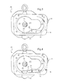
figure 3 est une vue du recto du carter d'huile de lafigure 2 (vu du côté engrenage), - la
figure 4 est une vue similaire du carter d'huile vu du côté engrenage de lafigure 3 dans lequel on a disposé un organe de raccordement, - la
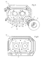
figure 5 est une vue en perspective des éléments du palier lubrifié, et - la
figure 6 est une vue schématique des éléments de lafigure 5 à l'état assemblé. - Sur ces figures, les éléments identiques portent les mêmes numéros de référence.
- Les
figures 1 à 6 illustrent un exemple de réalisation d'une pompe à vide de type sèche comportant deux arbres à lobes rotatifs de type « Roots ». Bien entendu, l'invention s'applique également à d'autres types de pompes à vide de type sèche, telles que de type « Claw », ou telles que des pompes à vide de type sèche à spirale ou à vis ou d'un autre principe similaire. - La pompe à vide 1 comporte un ou plusieurs étages de pompage en série 2 dans lesquels circule un gaz à pomper depuis une entrée d'admission vers une sortie de refoulement (non visibles). Les arbres rotatifs 3 (un seul est visible sur la
figure 1 ) s'étendent dans l'étage de pompage 2 par des rotors à lobes rotatifs 4, et sont entraînés du côté de l'étage de refoulement dans un compartiment d'entraînement moteur 5 de la pompe à vide 1. L'étage de pompage 2 est dit « sec » car en fonctionnement, les rotors 4 tournent à l'intérieur du carter 6 en sens opposé sans aucun contact mécanique entre les rotors 4 et le carter 6 de la pompe à vide 1, ce qui permet l'absence totale de lubrifiant. - La pompe à vide fonctionne à l'horizontale comme représenté sur la
figure 1 , c'est-à-dire qu'en fonctionnement de la pompe à vide, les arbres rotatifs 3 sont sensiblement parallèles au plan du sol. - Les arbres rotatifs 3 sont supportés en bout d'arbre par deux paliers lubrifiés, par exemple par de la graisse au niveau de l'étage d'aspiration (non visibles) et deux paliers lubrifiés 7a, 7b du compartiment d'entraînement moteur 5 du côté de l'étage de refoulement, par exemple lubrifiés par un lubrifiant liquide, tel que de l'huile. Les paliers lubrifiés 7a, 7b, sont pourvus de roulements 9 pour guider et supporter les arbres rotatifs 3.
- La pompe à vide 1 comporte un moteur (non représenté), logé dans le compartiment d'entraînement moteur 5, ainsi que des engrenages (non représentés) montés sur les arbres rotatifs respectifs 3 pour entraîner de façon synchronisée un arbre menant et un arbre mené.
- La pompe à vide 1 comporte un premier réservoir 28 comportant une première réserve de lubrifiant liquide 16a. Le premier réservoir 28 est en communication avec le palier lubrifié 7a dans un premier volume V1 (en pointillés sur la
figure 1 ). - La pompe à vide 1 comporte également un éclateur de lubrifiant 11, monté sur l'arbre rotatif menant 3 dans le premier réservoir 28, une extrémité de l'éclateur de lubrifiant 11 baignant dans la première réserve de lubrifiant liquide 16a. L'éclateur de lubrifiant 11 se présente par exemple sous la forme d'un disque monté coaxialement à l'arbre rotatif 3. En fonctionnement, la rotation de l'arbre menant 3 entraîne la rotation de l'éclateur de lubrifiant 11, générant ainsi un brouillard de lubrifiant dans les paliers 7a, 7b, qui permet la lubrification des roulements 9 de la pompe à vide 1.
- La pompe à vide 1 comporte en outre un dispositif d'étanchéité aux lubrifiants pour barrer le passage des lubrifiants depuis le compartiment d'entraînement moteur 5 vers les étages de pompage 2. Le dispositif d'étanchéité comporte un déflecteur à lubrifiant 12 (
figures 1 et5 ) et un joint annulaire 13 montés sur l'arbre rotatif respectif 3, le joint annulaire 13 étant monté entre le déflecteur à lubrifiant 12 et l'étage de pompage 2 et le déflecteur à lubrifiant 12 étant monté entre le joint annulaire 13 et le palier lubrifié 7a, 7b. - Le joint annulaire 13 est par exemple un joint annulaire frottant à double lèvres.
- Le déflecteur à lubrifiant 12 tourne solidairement avec l'arbre rotatif 3, ce qui permet de dévier le lubrifiant et les particules provenant du palier lubrifié 7a, 7b par centrifugation par exemple vers une gorge annulaire 14 ménagée dans le corps du compartiment d'entraînement moteur 5 face à l'extrémité périphérique du déflecteur à lubrifiant 12 (voir plus précisément les
figures 1 et5 ). Le déflecteur à lubrifiant 12 se présente par exemple sous la forme d'un disque monté coaxialement à l'arbre rotatif 3. - La pompe à vide 1 comporte un deuxième réservoir 15 ménagé dans le carter 6 de la pompe à vide 1, comportant une deuxième réserve de lubrifiant liquide 16b, tel que de l'huile. Le deuxième réservoir 15 est séparé du premier réservoir 28 par une paroi de séparation 20 présentant un trou de communication 34 mettant en communication la première et la deuxième réserve de lubrifiant liquide 16a, 16b. Un canal de retour de lubrifiant 17 de la pompe à vide 1, présente une entrée 18 située en regard du déflecteur à lubrifiant 12, par exemple dans la gorge annulaire 14. Le canal de retour de lubrifiant 17 s'étend dans le carter du corps du compartiment d'entraînement moteur 5, sous les paliers lubrifiés 7a, 7b, et débouche par une embouchure 19, dans le deuxième volume V2 du deuxième réservoir 15, au-dessus de la deuxième réserve de lubrifiant liquide 16b.
- En fonctionnement, le premier volume V1, contenant les paliers lubrifiés 7a, 7b et l'éclateur de lubrifiant 11, présente une atmosphère interne brouillée d'un mélange de gaz et de lubrifiant, généralement de l'air lubrifié d'huile, créé notamment par la rotation de l'éclateur de lubrifiant 11. Cette ambiance est séparée par la paroi de séparation 20, de l'ambiance du deuxième volume V2 du deuxième réservoir 15, dans lequel débouche le canal de retour de lubrifiant 17. Le deuxième réservoir 15 ne contenant pas d'éclateur de lubrifiant, ni aucun autre élément rotatif en mouvement en fonctionnement de la pompe à vide 1, présente une atmosphère gazeuse calme au-dessus du lubrifiant liquide 16b, sans brouillard de lubrifiant, les phases liquides et gazeuses étant bien séparées l'une de l'autre.
- Ainsi, lorsque du brouillard de lubrifiant est attiré des paliers lubrifiés 7a, 7b vers l'étage de pompage 2, le lubrifiant est dévié par le déflecteur à lubrifiant 12 dans la gorge annulaire 14, puis dans le canal de retour de lubrifiant 17 par l'effet de la force centrifuge jusqu'à se déverser dans la deuxième réserve de lubrifiant liquide 16b du deuxième réservoir 15.
- Puis, pendant les phases d'équilibrage de pression où la pression dans les paliers lubrifiés 7a, 7b est supérieure à la pression de l'étage de pompage 2, le lubrifiant liquide tombé au fond du deuxième réservoir 15 dans la deuxième réserve de lubrifiant liquide 16b, à un niveau plus bas que l'embouchure 19 du canal de retour de lubrifiant 17, ne peut pas remonter dans celui-ci. Au contraire, du gaz « sec », c'est-à-dire exempt de lubrifiant, situé dans le deuxième réservoir 15 au-dessus du niveau de lubrifiant liquide, va remplir le canal de retour de lubrifiant 17 et rétablir l'équilibrage des pressions de part et d'autre du dispositif d'étanchéité. La séparation du deuxième réservoir 15 permet ainsi d'éviter que l'air brouillé de lubrifiant contenu dans l'environnement huilé des paliers lubrifiés 7a, 7b en fonctionnement, n'entre dans le canal de retour de lubrifiant 17.
- Pour cela, et selon le mode de réalisation représenté sur les
figures 1 à 6 , le carter du compartiment d'entraînement moteur 5 comporte par exemple un stator moteur 21, un carter d'huile 22, et un flasque d'extrémité 23 (ou support HP (haute pression)) par exemple en fonte, s'assemblant ensemble et une paroi de séparation 20 séparant le deuxième volume V2 (rempli par des pointillés sur lafigure 1 ) du deuxième réservoir 15 du premier volume V1 comportant le premier réservoir 28 et les paliers lubrifiés 7a, 7b. - Mieux visible sur la
figure 2 , la paroi de séparation 20 est par exemple solidaire du carter d'huile 22 qui s'assemble au stator moteur 21. L'assemblage du stator moteur 21 et du carter d'huile 22 forme le deuxième volume V2 présentant au fond la deuxième réserve de lubrifiant liquide 16b. L'assemblage est réalisé de manière classique avec un joint torique 24 et des moyens de fixation. Le stator moteur 21 comporte en outre des moyens de refroidissement 26 du moteur par un fluide réfrigérant. Ces moyens sont en partie dissimulés par une résine dans laquelle un logement axial 27 est ménagé dans l'axe de rotation de l'arbre menant pour loger le rotor moteur (non représenté). - Le fond du premier volume V1 formé par le carter d'huile 22 et le flasque d'extrémité 23 assemblés comporte la première réserve de lubrifiant liquide 16a, pour lubrifier les éléments rotatifs des paliers lubrifiés 7a, 7b (
figures 3 et5 ). - On distingue sur l'envers du carter d'huile 22 en
figure 3 , un orifice de remplissage 30 en haut à droite du carter d'huile, communiquant avec le premier volume V1. L'orifice de remplissage 30 est obturé par un bouchon 31. On distingue également un repère en bas à droite du carter d'huile 22 pour le niveau de consigne N du lubrifiant liquide. Ce repère correspond à une portion transparente du carter d'huile 22 ménagée sur la tranche (non visible sur lafigure 3 ) pour guider le niveau de consigne N du remplissage de lubrifiant liquide 16a par l'utilisateur. Le carter d'huile 22 comprend également un orifice de purge 32 obstrué et communiquant avec le fond 28 et une partie de cuve 33 obstruée pour la vidange de la pompe à vide 1. - Comme on peut le voir sur la
figure 2 , la paroi de séparation 20 présente un trou de communication 34 au-dessous du niveau de consigne N du lubrifiant liquide pour la mise à niveau des liquides lubrifiants des première et deuxième réserves de lubrifiant liquide 16a, 16b. Le trou de communication 34 est donc situé au-dessous de l'embouchure 19 du canal de retour de fluide lubrifiant 17. On s'assure ainsi du niveau de lubrifiant liquide de la deuxième réserve 16b en même temps que du niveau de lubrifiant liquide de la première réserve 16a par les moyens de remplissage, purge, vidange du carter d'huile 22. - Par ailleurs, on calibre la conductance du passage d'arbre 35 de la paroi de séparation 20 et la conductance à l'embouchure 19 du canal de retour de lubrifiant 17, pour diriger un flux de gaz dans le canal de retour de lubrifiant 17 depuis le deuxième volume V2 vers le déflecteur à lubrifiant 12.
- Avec ce calibrage des conductances, lorsque la pression s'abaisse dans l'étage de pompage 2, elle s'abaisse plus vite dans le premier volume V1 comportant les paliers lubrifiés 7a, 7b, que dans le deuxième volume V2 du deuxième réservoir 15. Le deuxième volume V2 conserve alors une légère surpression par rapport au premier volume V1, d'environ 2 bars. Le gaz sec va alors s'engouffrer à travers le canal de retour de lubrifiant 17, et y être accéléré jusqu'à l'entrée 18 du canal de retour de lubrifiant 17, formant une barrière de gaz sec au niveau du déflecteur à lubrifiant 12. On favorise ainsi une accélération du flux de gaz dans le canal de retour de lubrifiant 17 depuis le deuxième volume V2 vers le déflecteur à lubrifiant 12 plutôt que depuis le premier volume V1 vers le deuxième volume V2.
- La conductance entre le premier V1 et le deuxième volume V2 est définie par l'espace ménagé entre l'arbre menant 3 et le passage d'arbre 35 de la paroi de séparation 20. On prévoit par exemple que l'écart entre le diamètre du passage d'arbre 35 et le diamètre de l'arbre rotatif 3 soit inférieur à 3 millimètres, de préférence de l'ordre de 2 millimètres. Et, on peut également prévoir que la dimension du diamètre interne de l'embouchure 19 du canal de retour de lubrifiant 17 soit inférieure à 5 millimètres, de préférence de l'ordre de 4 millimètres.
- Ainsi, le faible espace au niveau du passage d'arbre 35 favorise une surpression dans le deuxième volume V2 par rapport au premier volume V1 et la faible conductance du canal de retour de lubrifiant 17 favorise l'accélération du gaz sec dans le canal de retour de fluide lubrifiant 17, ce qui permet la formation de la barrière de gaz au niveau du déflecteur à lubrifiant 12.
- En outre, on peut prévoir que le canal de retour de lubrifiant 17 comporte une première portion de canal 17a associée au premier palier lubrifié 7a, une deuxième portion de canal 17b associée au deuxième palier lubrifié 7b et une portion de canal commune 17c à la première et deuxième portion de canal 17a, 17b. Chaque portion de canal 17a, et 17b présente une entrée située dans la gorge annulaire 14 en regard du déflecteur de lubrifiant 12 associé au palier lubrifié 7a, 7b respectif. Le canal de retour de fluide lubrifiant 17 communique ainsi entre le premier et le deuxième paliers lubrifiés 7a, 7b afin de conserver un équilibre de lubrifiant sur les deux paliers lubrifiés 7a, 7b.
- Pour cela, et comme visible sur la
figure 5 , le canal de retour de lubrifiant 17 comporte une rainure communicante 36 entre la première portion de canal 17a et la deuxième portion de canal 17b. Le canal de retour de lubrifiant 17 comporte en outre un organe de raccordement 37 s'assemblant sur la rainure communicante 36 et débouchant par un tube de jonction 38. Une fois l'organe de raccordement 37 assemblé entre le carter d'huile 22 et le flasque d'extrémité 23, le tube de jonction 38 débouche de la paroi de séparation 20 dans le deuxième volume V2 par l'embouchure 19. - L'organe de raccordement 37 comporte par exemple une plaquette 39 fermant la rainure communicante 36 et un tube de jonction 38 excentré du milieu de la plaquette 39 faisant saillie perpendiculairement de la plaquette 39. Le tube de jonction 38 est excentré pour permettre la rotation des éléments rotatifs, tel que l'éclateur de lubrifiant 11 du palier lubrifié 7a de l'arbre menant 3.
- On limite ainsi la migration du lubrifiant vers le dispositif d'étanchéité par le canal de retour de lubrifiant 17 et par les paliers lubrifiés 7a, 7b, en s'assurant que le lubrifiant ne court-circuite pas les paliers lubrifiés 7a, 7b du compartiment d'entrainement moteur 5 pour arriver directement sur le joint annulaire 13 sans être traité par le déflecteur à lubrifiant 12, ce qui permet d'augmenter la durée de vie du joint annulaire 13.
- Bien que l'on ait décrit un dispositif d'étanchéité et des réservoirs de lubrifiant liquide, agencés côté refoulement de la pompe à vide, le dispositif d'étanchéité et les réservoirs de lubrifiant liquide peuvent tout aussi bien être agencés côté aspiration, à l'extrémité de l'étage de plus basse pression, en remplacement d'une lubrification par de la graisse.
Claims (8)
- Pompe à vide de type sèche comportant :- au moins un étage de pompage (2),- au moins un arbre rotatif (3) supporté par un palier lubrifié (7a, 7b),- au moins un déflecteur à lubrifiant (12) et un joint annulaire (13) montés sur l'arbre rotatif (3), le joint annulaire (13) étant monté entre le déflecteur à lubrifiant (12) et l'étage de pompage (2), le déflecteur à lubrifiant (12) étant monté entre le palier lubrifié (7a, 7b) et le joint annulaire (13),- un premier réservoir (28) comportant une première réserve de lubrifiant liquide (16a), ledit premier réservoir (28) étant en communication avec le palier lubrifié (7a, 7b) dans un premier volume (V1),- un éclateur de lubrifiant, monté sur l'arbre rotatif (3) dans le premier réservoir (28), une extrémité de l'éclateur de lubrifiant baignant dans la première réserve de lubrifiant liquide (16a),
caractérisée en ce que la pompe à vide comporte un deuxième réservoir (15) comportant une deuxième réserve de lubrifiant liquide (16b), le deuxième réservoir (15) étant séparé du premier réservoir (28) par une paroi de séparation (20) présentant un trou de communication (34) mettant en communication la première et la deuxième réserve de lubrifiant liquide (16a, 16b) et en ce qu'un canal de retour de lubrifiant (17) dont une entrée (18) située en regard dudit déflecteur à lubrifiant (12), débouche dans le deuxième volume (V2) du deuxième réservoir (15), au-dessus de la deuxième réserve de lubrifiant liquide (16b). - Pompe à vide selon la revendication 1, dans laquelle le deuxième réservoir (15) et ledit canal de retour de lubrifiant (17) sont ménagés dans le carter (6) d'un compartiment d'entraînement moteur (5) de ladite pompe à vide (1).
- Pompe à vide selon l'une des revendications précédentes, dans laquelle la dimension du diamètre interne de l'embouchure (19) du canal de retour de lubrifiant (17) est inférieure à 5 millimètres.
- Pompe à vide selon l'une des revendications précédentes, dans laquelle l'écart entre le diamètre du passage d'arbre (35) de la paroi de séparation (20) et le diamètre de l'arbre rotatif (3) est inférieure à 3 millimètres.
- Pompe à vide selon l'une des revendications 1 à 4, dans laquelle une gorge annulaire (14) est ménagée dans le carter (6) face à une extrémité périphérique du déflecteur à lubrifiant (12) et communique avec l'entrée (18) dudit canal de retour de lubrifiant (17).
- Pompe à vide selon l'une des revendications 1 à 5, comportant deux arbres rotatifs (3), lesdits arbres rotatifs (3) étant supportés par un palier lubrifié respectif (7a, 7b), et dans laquelle ledit canal de retour de lubrifiant (17) comporte une première portion de canal (17a) associée à un premier palier lubrifié (7a), une deuxième portion de canal (17b) associée à un deuxième palier lubrifié (7b) et une portion de canal commune (17c) à ladite première et deuxième portion de canal (17a, 17b).
- Pompe à vide selon la revendication 6, dans laquelle le canal de retour de lubrifiant (17) comporte une rainure communicante (36) entre ladite première portion de canal (17a) et ladite deuxième portion de canal (17b) et ledit canal de retour de lubrifiant (17) comporte un organe de raccordement (37) s'assemblant sur ladite rainure communicante (36) et débouchant par un tube de jonction (38).
- Pompe à vide selon la revendication 7, dans laquelle ledit organe de raccordement (37) comporte une plaquette (39) fermant ladite rainure communicante (36) et un tube de jonction (38) excentré faisant saillie perpendiculairement de ladite plaquette (39).
Applications Claiming Priority (1)
| Application Number | Priority Date | Filing Date | Title |
|---|---|---|---|
| FR1002756A FR2962173B1 (fr) | 2010-06-30 | 2010-06-30 | Pompe a vide de type seche |
Publications (2)
| Publication Number | Publication Date |
|---|---|
| EP2402613A1 true EP2402613A1 (fr) | 2012-01-04 |
| EP2402613B1 EP2402613B1 (fr) | 2015-10-21 |
Family
ID=43532866
Family Applications (1)
| Application Number | Title | Priority Date | Filing Date |
|---|---|---|---|
| EP11171594.2A Active EP2402613B1 (fr) | 2010-06-30 | 2011-06-27 | Pompe à vide de type sèche |
Country Status (6)
| Country | Link |
|---|---|
| US (1) | US8858204B2 (fr) |
| EP (1) | EP2402613B1 (fr) |
| JP (1) | JP5759800B2 (fr) |
| KR (1) | KR101813281B1 (fr) |
| CN (1) | CN102312837B (fr) |
| FR (1) | FR2962173B1 (fr) |
Cited By (1)
| Publication number | Priority date | Publication date | Assignee | Title |
|---|---|---|---|---|
| WO2017076803A1 (fr) * | 2015-11-03 | 2017-05-11 | Leybold Gmbh | Pompe à vide sèche |
Families Citing this family (8)
| Publication number | Priority date | Publication date | Assignee | Title |
|---|---|---|---|---|
| US10204365B2 (en) | 2010-07-07 | 2019-02-12 | T-Mobile Usa, Inc. | Managing service provider service options |
| DE202014007850U1 (de) * | 2014-09-27 | 2016-01-05 | Oerlikon Leybold Vacuum Gmbh | Vakuumpumpe |
| IT201700096517A1 (it) * | 2017-08-28 | 2019-02-28 | Jurop S P A | Compressore volumetrico con dispositivo di raccolta lubrificante |
| CN110761752B (zh) * | 2019-11-21 | 2023-08-22 | 西安德林石油工程有限公司 | 一种天然气井口抽气增压方法以及装置 |
| CN110761746B (zh) * | 2019-11-21 | 2023-08-11 | 西安德林石油工程有限公司 | 一种气井排液方法以及装置 |
| CN115434902B (zh) * | 2022-11-07 | 2022-12-30 | 中国空气动力研究与发展中心超高速空气动力研究所 | 一种大流量高真空抽气系统的设计方法 |
| CN116006464B (zh) * | 2023-02-03 | 2024-02-23 | 安徽应流机电股份有限公司 | 特殊风冷罗茨真空泵 |
| GB2642331A (en) * | 2024-07-03 | 2026-01-07 | Edwards Ltd | Vacuum Pump |
Citations (7)
| Publication number | Priority date | Publication date | Assignee | Title |
|---|---|---|---|---|
| JPH03130592A (ja) * | 1989-10-12 | 1991-06-04 | Anlet Co Ltd | 内部洗浄可能な多段式ルーツ真空ポンプ |
| US5044895A (en) * | 1984-12-22 | 1991-09-03 | Leybold Aktiengesellschaft | Oil supply device for a rotary machine |
| DE19736017A1 (de) * | 1997-08-20 | 1999-02-25 | Peter Frieden | Trockenverdichtende Vakuumpumpe oder Kompressor |
| DE19820523A1 (de) * | 1998-05-08 | 1999-11-11 | Peter Frieden | Schraubenspindel-Vakuumpumpe mit Rotorkühlung |
| EP1975410A1 (fr) * | 2007-03-30 | 2008-10-01 | Anest Iwata Corporation | Procédé d'étanchéification d'arbre de rotor et structure de compresseur rotatif sans huile |
| WO2008142437A1 (fr) * | 2007-05-18 | 2008-11-27 | Edwards Limited | Pompe à vide |
| FR2920207A1 (fr) * | 2007-08-23 | 2009-02-27 | Alcatel Lucent Sas | Pompe a vide de type seche comportant un dispositif d'etancheite aux fluides lubrifiants et elements centrifugeur equipant un tel dispositif |
Family Cites Families (5)
| Publication number | Priority date | Publication date | Assignee | Title |
|---|---|---|---|---|
| US1696882A (en) * | 1925-12-16 | 1928-12-25 | Connersville Blower Co | Blower |
| DE1939717B2 (de) * | 1969-08-05 | 1978-03-23 | Leybold-Heraeus Gmbh & Co Kg, 5000 Koeln | Waelzkolbenpumpe |
| DE3344953A1 (de) * | 1983-12-13 | 1985-06-20 | Leybold-Heraeus GmbH, 5000 Köln | Zweiwellen-vakuumpumpe mit getrieberaum-evakuierung |
| JPS63158595U (fr) * | 1987-04-03 | 1988-10-18 | ||
| JPH0447189A (ja) * | 1990-06-15 | 1992-02-17 | Hitachi Ltd | ドライスクリユー真空ポンプ |
-
2010
- 2010-06-30 FR FR1002756A patent/FR2962173B1/fr not_active Expired - Fee Related
-
2011
- 2011-06-23 JP JP2011139186A patent/JP5759800B2/ja active Active
- 2011-06-27 EP EP11171594.2A patent/EP2402613B1/fr active Active
- 2011-06-27 US US13/170,174 patent/US8858204B2/en active Active
- 2011-06-30 CN CN201110211420.0A patent/CN102312837B/zh active Active
- 2011-06-30 KR KR1020110064640A patent/KR101813281B1/ko active Active
Patent Citations (7)
| Publication number | Priority date | Publication date | Assignee | Title |
|---|---|---|---|---|
| US5044895A (en) * | 1984-12-22 | 1991-09-03 | Leybold Aktiengesellschaft | Oil supply device for a rotary machine |
| JPH03130592A (ja) * | 1989-10-12 | 1991-06-04 | Anlet Co Ltd | 内部洗浄可能な多段式ルーツ真空ポンプ |
| DE19736017A1 (de) * | 1997-08-20 | 1999-02-25 | Peter Frieden | Trockenverdichtende Vakuumpumpe oder Kompressor |
| DE19820523A1 (de) * | 1998-05-08 | 1999-11-11 | Peter Frieden | Schraubenspindel-Vakuumpumpe mit Rotorkühlung |
| EP1975410A1 (fr) * | 2007-03-30 | 2008-10-01 | Anest Iwata Corporation | Procédé d'étanchéification d'arbre de rotor et structure de compresseur rotatif sans huile |
| WO2008142437A1 (fr) * | 2007-05-18 | 2008-11-27 | Edwards Limited | Pompe à vide |
| FR2920207A1 (fr) * | 2007-08-23 | 2009-02-27 | Alcatel Lucent Sas | Pompe a vide de type seche comportant un dispositif d'etancheite aux fluides lubrifiants et elements centrifugeur equipant un tel dispositif |
Cited By (4)
| Publication number | Priority date | Publication date | Assignee | Title |
|---|---|---|---|---|
| WO2017076803A1 (fr) * | 2015-11-03 | 2017-05-11 | Leybold Gmbh | Pompe à vide sèche |
| CN108431422A (zh) * | 2015-11-03 | 2018-08-21 | 莱宝有限公司 | 干式真空泵 |
| CN108431422B (zh) * | 2015-11-03 | 2019-07-23 | 莱宝有限公司 | 干式真空泵 |
| US10851783B2 (en) | 2015-11-03 | 2020-12-01 | Leybold Gmbh | Dry vacuum pump with pressurized bearing and seal |
Also Published As
| Publication number | Publication date |
|---|---|
| US20120003105A1 (en) | 2012-01-05 |
| CN102312837B (zh) | 2015-08-19 |
| KR101813281B1 (ko) | 2018-01-30 |
| FR2962173B1 (fr) | 2012-08-03 |
| JP5759800B2 (ja) | 2015-08-05 |
| KR20120002490A (ko) | 2012-01-05 |
| CN102312837A (zh) | 2012-01-11 |
| FR2962173A1 (fr) | 2012-01-06 |
| US8858204B2 (en) | 2014-10-14 |
| EP2402613B1 (fr) | 2015-10-21 |
| JP2012013074A (ja) | 2012-01-19 |
Similar Documents
| Publication | Publication Date | Title |
|---|---|---|
| EP2402613B1 (fr) | Pompe à vide de type sèche | |
| EP3247924B1 (fr) | Intégration d'une pompe en fût de pignon | |
| EP2183508B1 (fr) | Pompe a vide de type seche comportant un dispositif d'etancheite aux fluides lubrifiants et element centrifugeur equipant un tel dispositif | |
| FR2675213A1 (fr) | Systeme formant barriere pour l'huile de lubrification des paliers d'un compresseur centrifuge muni de joints d'etancheite a labyrinthe installe dans un environnement confine. | |
| FR2991733A1 (fr) | Dispositif de compression et systeme thermodynamique comprenant un tel dispositif de compression | |
| FR2929325A1 (fr) | Dispositif et procede d'equilibrage de pression dans une enceinte palier de turboreacteur | |
| EP0368122A1 (fr) | Pompe à vide du type roots multiétagé | |
| EP1933077A1 (fr) | Procédé et système de lubrification d'une turbomachine | |
| FR2913061A1 (fr) | Systeme de deshuilage pour moteur d'aeronef. | |
| FR2928566A1 (fr) | Deshuileur centrifuge a section de passage variable | |
| FR3035164A1 (fr) | Transmission | |
| EP0063062B1 (fr) | Dispositif d'étanchéité pour machine rotative à fluide hydraulique | |
| EP3081817A1 (fr) | Machine équipée d'un compresseur ou d'une pompe | |
| FR3090035A1 (fr) | Dispositif de deshuilage et d’etancheite d’une enceinte de lubrification de turbomachine | |
| FR2482208A1 (fr) | ||
| EP3131656B1 (fr) | Filtrage d'un flux gaz/particules | |
| FR3021075B1 (fr) | Compresseur a spirales | |
| FR3147585A1 (fr) | Lubrification de paliers dans une turbomachine d’aéronef | |
| FR3124236A1 (fr) | Pompe à vide | |
| FR3148459A1 (fr) | Pompe à vide | |
| FR3067386B1 (fr) | Machine de detente | |
| FR3079886A1 (fr) | Pompe a vide de type seche | |
| EP0277852B1 (fr) | Dispositif de lubrification de piston | |
| EP3724506A1 (fr) | Machine volumetrique a spirales | |
| FR3119209A1 (fr) | Pompe à vide de type sèche et groupe de pompage |
Legal Events
| Date | Code | Title | Description |
|---|---|---|---|
| AK | Designated contracting states |
Kind code of ref document: A1 Designated state(s): AL AT BE BG CH CY CZ DE DK EE ES FI FR GB GR HR HU IE IS IT LI LT LU LV MC MK MT NL NO PL PT RO RS SE SI SK SM TR |
|
| AX | Request for extension of the european patent |
Extension state: BA ME |
|
| PUAI | Public reference made under article 153(3) epc to a published international application that has entered the european phase |
Free format text: ORIGINAL CODE: 0009012 |
|
| 17P | Request for examination filed |
Effective date: 20120521 |
|
| GRAP | Despatch of communication of intention to grant a patent |
Free format text: ORIGINAL CODE: EPIDOSNIGR1 |
|
| INTG | Intention to grant announced |
Effective date: 20150528 |
|
| GRAS | Grant fee paid |
Free format text: ORIGINAL CODE: EPIDOSNIGR3 |
|
| GRAA | (expected) grant |
Free format text: ORIGINAL CODE: 0009210 |
|
| AK | Designated contracting states |
Kind code of ref document: B1 Designated state(s): AL AT BE BG CH CY CZ DE DK EE ES FI FR GB GR HR HU IE IS IT LI LT LU LV MC MK MT NL NO PL PT RO RS SE SI SK SM TR |
|
| REG | Reference to a national code |
Ref country code: GB Ref legal event code: FG4D Free format text: NOT ENGLISH Ref country code: NL Ref legal event code: MP Effective date: 20151021 |
|
| REG | Reference to a national code |
Ref country code: CH Ref legal event code: EP |
|
| REG | Reference to a national code |
Ref country code: AT Ref legal event code: REF Ref document number: 756800 Country of ref document: AT Kind code of ref document: T Effective date: 20151115 |
|
| REG | Reference to a national code |
Ref country code: IE Ref legal event code: FG4D Free format text: LANGUAGE OF EP DOCUMENT: FRENCH |
|
| REG | Reference to a national code |
Ref country code: DE Ref legal event code: R096 Ref document number: 602011020733 Country of ref document: DE |
|
| RAP2 | Party data changed (patent owner data changed or rights of a patent transferred) |
Owner name: PFEIFFER VACUUM |
|
| REG | Reference to a national code |
Ref country code: FR Ref legal event code: CD Owner name: PFEIFFER VACCUUM, FR Effective date: 20160118 |
|
| REG | Reference to a national code |
Ref country code: LT Ref legal event code: MG4D |
|
| REG | Reference to a national code |
Ref country code: AT Ref legal event code: MK05 Ref document number: 756800 Country of ref document: AT Kind code of ref document: T Effective date: 20151021 |
|
| PG25 | Lapsed in a contracting state [announced via postgrant information from national office to epo] |
Ref country code: IT Free format text: LAPSE BECAUSE OF FAILURE TO SUBMIT A TRANSLATION OF THE DESCRIPTION OR TO PAY THE FEE WITHIN THE PRESCRIBED TIME-LIMIT Effective date: 20151021 Ref country code: IS Free format text: LAPSE BECAUSE OF FAILURE TO SUBMIT A TRANSLATION OF THE DESCRIPTION OR TO PAY THE FEE WITHIN THE PRESCRIBED TIME-LIMIT Effective date: 20160221 Ref country code: LT Free format text: LAPSE BECAUSE OF FAILURE TO SUBMIT A TRANSLATION OF THE DESCRIPTION OR TO PAY THE FEE WITHIN THE PRESCRIBED TIME-LIMIT Effective date: 20151021 Ref country code: ES Free format text: LAPSE BECAUSE OF FAILURE TO SUBMIT A TRANSLATION OF THE DESCRIPTION OR TO PAY THE FEE WITHIN THE PRESCRIBED TIME-LIMIT Effective date: 20151021 Ref country code: NL Free format text: LAPSE BECAUSE OF FAILURE TO SUBMIT A TRANSLATION OF THE DESCRIPTION OR TO PAY THE FEE WITHIN THE PRESCRIBED TIME-LIMIT Effective date: 20151021 Ref country code: HR Free format text: LAPSE BECAUSE OF FAILURE TO SUBMIT A TRANSLATION OF THE DESCRIPTION OR TO PAY THE FEE WITHIN THE PRESCRIBED TIME-LIMIT Effective date: 20151021 Ref country code: NO Free format text: LAPSE BECAUSE OF FAILURE TO SUBMIT A TRANSLATION OF THE DESCRIPTION OR TO PAY THE FEE WITHIN THE PRESCRIBED TIME-LIMIT Effective date: 20160121 |
|
| PG25 | Lapsed in a contracting state [announced via postgrant information from national office to epo] |
Ref country code: LV Free format text: LAPSE BECAUSE OF FAILURE TO SUBMIT A TRANSLATION OF THE DESCRIPTION OR TO PAY THE FEE WITHIN THE PRESCRIBED TIME-LIMIT Effective date: 20151021 Ref country code: PL Free format text: LAPSE BECAUSE OF FAILURE TO SUBMIT A TRANSLATION OF THE DESCRIPTION OR TO PAY THE FEE WITHIN THE PRESCRIBED TIME-LIMIT Effective date: 20151021 Ref country code: RS Free format text: LAPSE BECAUSE OF FAILURE TO SUBMIT A TRANSLATION OF THE DESCRIPTION OR TO PAY THE FEE WITHIN THE PRESCRIBED TIME-LIMIT Effective date: 20151021 Ref country code: GR Free format text: LAPSE BECAUSE OF FAILURE TO SUBMIT A TRANSLATION OF THE DESCRIPTION OR TO PAY THE FEE WITHIN THE PRESCRIBED TIME-LIMIT Effective date: 20160122 Ref country code: AT Free format text: LAPSE BECAUSE OF FAILURE TO SUBMIT A TRANSLATION OF THE DESCRIPTION OR TO PAY THE FEE WITHIN THE PRESCRIBED TIME-LIMIT Effective date: 20151021 Ref country code: PT Free format text: LAPSE BECAUSE OF FAILURE TO SUBMIT A TRANSLATION OF THE DESCRIPTION OR TO PAY THE FEE WITHIN THE PRESCRIBED TIME-LIMIT Effective date: 20160222 Ref country code: FI Free format text: LAPSE BECAUSE OF FAILURE TO SUBMIT A TRANSLATION OF THE DESCRIPTION OR TO PAY THE FEE WITHIN THE PRESCRIBED TIME-LIMIT Effective date: 20151021 Ref country code: SE Free format text: LAPSE BECAUSE OF FAILURE TO SUBMIT A TRANSLATION OF THE DESCRIPTION OR TO PAY THE FEE WITHIN THE PRESCRIBED TIME-LIMIT Effective date: 20151021 |
|
| REG | Reference to a national code |
Ref country code: FR Ref legal event code: PLFP Year of fee payment: 6 |
|
| REG | Reference to a national code |
Ref country code: DE Ref legal event code: R097 Ref document number: 602011020733 Country of ref document: DE |
|
| PG25 | Lapsed in a contracting state [announced via postgrant information from national office to epo] |
Ref country code: CZ Free format text: LAPSE BECAUSE OF FAILURE TO SUBMIT A TRANSLATION OF THE DESCRIPTION OR TO PAY THE FEE WITHIN THE PRESCRIBED TIME-LIMIT Effective date: 20151021 |
|
| PLBE | No opposition filed within time limit |
Free format text: ORIGINAL CODE: 0009261 |
|
| STAA | Information on the status of an ep patent application or granted ep patent |
Free format text: STATUS: NO OPPOSITION FILED WITHIN TIME LIMIT |
|
| PG25 | Lapsed in a contracting state [announced via postgrant information from national office to epo] |
Ref country code: DK Free format text: LAPSE BECAUSE OF FAILURE TO SUBMIT A TRANSLATION OF THE DESCRIPTION OR TO PAY THE FEE WITHIN THE PRESCRIBED TIME-LIMIT Effective date: 20151021 Ref country code: SK Free format text: LAPSE BECAUSE OF FAILURE TO SUBMIT A TRANSLATION OF THE DESCRIPTION OR TO PAY THE FEE WITHIN THE PRESCRIBED TIME-LIMIT Effective date: 20151021 Ref country code: SM Free format text: LAPSE BECAUSE OF FAILURE TO SUBMIT A TRANSLATION OF THE DESCRIPTION OR TO PAY THE FEE WITHIN THE PRESCRIBED TIME-LIMIT Effective date: 20151021 Ref country code: EE Free format text: LAPSE BECAUSE OF FAILURE TO SUBMIT A TRANSLATION OF THE DESCRIPTION OR TO PAY THE FEE WITHIN THE PRESCRIBED TIME-LIMIT Effective date: 20151021 Ref country code: RO Free format text: LAPSE BECAUSE OF FAILURE TO SUBMIT A TRANSLATION OF THE DESCRIPTION OR TO PAY THE FEE WITHIN THE PRESCRIBED TIME-LIMIT Effective date: 20151021 |
|
| 26N | No opposition filed |
Effective date: 20160722 |
|
| REG | Reference to a national code |
Ref country code: DE Ref legal event code: R081 Ref document number: 602011020733 Country of ref document: DE Owner name: PFEIFFER VACUUM, FR Free format text: FORMER OWNER: ADIXEN VACUUM PRODUCTS, ANNECY, FR |
|
| REG | Reference to a national code |
Ref country code: DE Ref legal event code: R082 Ref document number: 602011020733 Country of ref document: DE |
|
| PG25 | Lapsed in a contracting state [announced via postgrant information from national office to epo] |
Ref country code: SI Free format text: LAPSE BECAUSE OF FAILURE TO SUBMIT A TRANSLATION OF THE DESCRIPTION OR TO PAY THE FEE WITHIN THE PRESCRIBED TIME-LIMIT Effective date: 20151021 |
|
| PG25 | Lapsed in a contracting state [announced via postgrant information from national office to epo] |
Ref country code: BE Free format text: LAPSE BECAUSE OF NON-PAYMENT OF DUE FEES Effective date: 20160630 |
|
| PG25 | Lapsed in a contracting state [announced via postgrant information from national office to epo] |
Ref country code: MC Free format text: LAPSE BECAUSE OF FAILURE TO SUBMIT A TRANSLATION OF THE DESCRIPTION OR TO PAY THE FEE WITHIN THE PRESCRIBED TIME-LIMIT Effective date: 20151021 |
|
| REG | Reference to a national code |
Ref country code: CH Ref legal event code: PL |
|
| GBPC | Gb: european patent ceased through non-payment of renewal fee |
Effective date: 20160627 |
|
| REG | Reference to a national code |
Ref country code: IE Ref legal event code: MM4A |
|
| PG25 | Lapsed in a contracting state [announced via postgrant information from national office to epo] |
Ref country code: LI Free format text: LAPSE BECAUSE OF NON-PAYMENT OF DUE FEES Effective date: 20160630 Ref country code: CH Free format text: LAPSE BECAUSE OF NON-PAYMENT OF DUE FEES Effective date: 20160630 |
|
| PG25 | Lapsed in a contracting state [announced via postgrant information from national office to epo] |
Ref country code: IE Free format text: LAPSE BECAUSE OF NON-PAYMENT OF DUE FEES Effective date: 20160627 Ref country code: GB Free format text: LAPSE BECAUSE OF NON-PAYMENT OF DUE FEES Effective date: 20160627 |
|
| REG | Reference to a national code |
Ref country code: FR Ref legal event code: PLFP Year of fee payment: 7 |
|
| PG25 | Lapsed in a contracting state [announced via postgrant information from national office to epo] |
Ref country code: HU Free format text: LAPSE BECAUSE OF FAILURE TO SUBMIT A TRANSLATION OF THE DESCRIPTION OR TO PAY THE FEE WITHIN THE PRESCRIBED TIME-LIMIT; INVALID AB INITIO Effective date: 20110627 Ref country code: CY Free format text: LAPSE BECAUSE OF FAILURE TO SUBMIT A TRANSLATION OF THE DESCRIPTION OR TO PAY THE FEE WITHIN THE PRESCRIBED TIME-LIMIT Effective date: 20151021 |
|
| REG | Reference to a national code |
Ref country code: FR Ref legal event code: PLFP Year of fee payment: 8 |
|
| PG25 | Lapsed in a contracting state [announced via postgrant information from national office to epo] |
Ref country code: LU Free format text: LAPSE BECAUSE OF NON-PAYMENT OF DUE FEES Effective date: 20160627 Ref country code: TR Free format text: LAPSE BECAUSE OF FAILURE TO SUBMIT A TRANSLATION OF THE DESCRIPTION OR TO PAY THE FEE WITHIN THE PRESCRIBED TIME-LIMIT Effective date: 20151021 Ref country code: MK Free format text: LAPSE BECAUSE OF FAILURE TO SUBMIT A TRANSLATION OF THE DESCRIPTION OR TO PAY THE FEE WITHIN THE PRESCRIBED TIME-LIMIT Effective date: 20151021 Ref country code: MT Free format text: LAPSE BECAUSE OF FAILURE TO SUBMIT A TRANSLATION OF THE DESCRIPTION OR TO PAY THE FEE WITHIN THE PRESCRIBED TIME-LIMIT Effective date: 20151021 |
|
| PG25 | Lapsed in a contracting state [announced via postgrant information from national office to epo] |
Ref country code: BG Free format text: LAPSE BECAUSE OF FAILURE TO SUBMIT A TRANSLATION OF THE DESCRIPTION OR TO PAY THE FEE WITHIN THE PRESCRIBED TIME-LIMIT Effective date: 20151021 |
|
| PG25 | Lapsed in a contracting state [announced via postgrant information from national office to epo] |
Ref country code: AL Free format text: LAPSE BECAUSE OF FAILURE TO SUBMIT A TRANSLATION OF THE DESCRIPTION OR TO PAY THE FEE WITHIN THE PRESCRIBED TIME-LIMIT Effective date: 20151021 |
|
| P01 | Opt-out of the competence of the unified patent court (upc) registered |
Effective date: 20230524 |
|
| PGFP | Annual fee paid to national office [announced via postgrant information from national office to epo] |
Ref country code: DE Payment date: 20250630 Year of fee payment: 15 |
|
| PGFP | Annual fee paid to national office [announced via postgrant information from national office to epo] |
Ref country code: FR Payment date: 20260629 Year of fee payment: 16 |