EP2402197A1 - Vehicle front structure - Google Patents
Vehicle front structure Download PDFInfo
- Publication number
- EP2402197A1 EP2402197A1 EP09840744A EP09840744A EP2402197A1 EP 2402197 A1 EP2402197 A1 EP 2402197A1 EP 09840744 A EP09840744 A EP 09840744A EP 09840744 A EP09840744 A EP 09840744A EP 2402197 A1 EP2402197 A1 EP 2402197A1
- Authority
- EP
- European Patent Office
- Prior art keywords
- vehicle
- vehicle front
- cooling
- unit
- air conditioning
- Prior art date
- Legal status (The legal status is an assumption and is not a legal conclusion. Google has not performed a legal analysis and makes no representation as to the accuracy of the status listed.)
- Granted
Links
Images


Classifications
-
- F—MECHANICAL ENGINEERING; LIGHTING; HEATING; WEAPONS; BLASTING
- F01—MACHINES OR ENGINES IN GENERAL; ENGINE PLANTS IN GENERAL; STEAM ENGINES
- F01P—COOLING OF MACHINES OR ENGINES IN GENERAL; COOLING OF INTERNAL-COMBUSTION ENGINES
- F01P11/00—Component parts, details, or accessories not provided for in, or of interest apart from, groups F01P1/00 - F01P9/00
- F01P11/10—Guiding or ducting cooling-air, to, or from, liquid-to-air heat exchangers
-
- B—PERFORMING OPERATIONS; TRANSPORTING
- B60—VEHICLES IN GENERAL
- B60H—ARRANGEMENTS OF HEATING, COOLING, VENTILATING OR OTHER AIR-TREATING DEVICES SPECIALLY ADAPTED FOR PASSENGER OR GOODS SPACES OF VEHICLES
- B60H1/00—Heating, cooling or ventilating [HVAC] devices
- B60H1/00507—Details, e.g. mounting arrangements, desaeration devices
- B60H1/00514—Details of air conditioning housings
- B60H1/00535—Mounting or fastening of the housing to the vehicle
-
- B—PERFORMING OPERATIONS; TRANSPORTING
- B60—VEHICLES IN GENERAL
- B60H—ARRANGEMENTS OF HEATING, COOLING, VENTILATING OR OTHER AIR-TREATING DEVICES SPECIALLY ADAPTED FOR PASSENGER OR GOODS SPACES OF VEHICLES
- B60H1/00—Heating, cooling or ventilating [HVAC] devices
- B60H1/00507—Details, e.g. mounting arrangements, desaeration devices
- B60H1/00514—Details of air conditioning housings
- B60H1/00542—Modular assemblies
-
- B—PERFORMING OPERATIONS; TRANSPORTING
- B60—VEHICLES IN GENERAL
- B60K—ARRANGEMENT OR MOUNTING OF PROPULSION UNITS OR OF TRANSMISSIONS IN VEHICLES; ARRANGEMENT OR MOUNTING OF PLURAL DIVERSE PRIME-MOVERS IN VEHICLES; AUXILIARY DRIVES FOR VEHICLES; INSTRUMENTATION OR DASHBOARDS FOR VEHICLES; ARRANGEMENTS IN CONNECTION WITH COOLING, AIR INTAKE, GAS EXHAUST OR FUEL SUPPLY OF PROPULSION UNITS IN VEHICLES
- B60K11/00—Arrangement in connection with cooling of propulsion units
- B60K11/02—Arrangement in connection with cooling of propulsion units with liquid cooling
- B60K11/04—Arrangement or mounting of radiators, radiator shutters, or radiator blinds
-
- B—PERFORMING OPERATIONS; TRANSPORTING
- B60—VEHICLES IN GENERAL
- B60R—VEHICLES, VEHICLE FITTINGS, OR VEHICLE PARTS, NOT OTHERWISE PROVIDED FOR
- B60R19/00—Wheel guards; Radiator guards, e.g. grilles; Obstruction removers; Fittings damping bouncing force in collisions
- B60R19/02—Bumpers, i.e. impact receiving or absorbing members for protecting vehicles or fending off blows from other vehicles or objects
- B60R19/24—Arrangements for mounting bumpers on vehicles
- B60R19/26—Arrangements for mounting bumpers on vehicles comprising yieldable mounting means
- B60R19/30—Elastomeric material
-
- B—PERFORMING OPERATIONS; TRANSPORTING
- B60—VEHICLES IN GENERAL
- B60R—VEHICLES, VEHICLE FITTINGS, OR VEHICLE PARTS, NOT OTHERWISE PROVIDED FOR
- B60R19/00—Wheel guards; Radiator guards, e.g. grilles; Obstruction removers; Fittings damping bouncing force in collisions
- B60R19/02—Bumpers, i.e. impact receiving or absorbing members for protecting vehicles or fending off blows from other vehicles or objects
- B60R19/24—Arrangements for mounting bumpers on vehicles
- B60R19/26—Arrangements for mounting bumpers on vehicles comprising yieldable mounting means
- B60R19/34—Arrangements for mounting bumpers on vehicles comprising yieldable mounting means destroyed upon impact, e.g. one-shot type
-
- B—PERFORMING OPERATIONS; TRANSPORTING
- B60—VEHICLES IN GENERAL
- B60H—ARRANGEMENTS OF HEATING, COOLING, VENTILATING OR OTHER AIR-TREATING DEVICES SPECIALLY ADAPTED FOR PASSENGER OR GOODS SPACES OF VEHICLES
- B60H1/00—Heating, cooling or ventilating [HVAC] devices
- B60H1/00007—Combined heating, ventilating, or cooling devices
- B60H1/00207—Combined heating, ventilating, or cooling devices characterised by the position of the HVAC devices with respect to the passenger compartment
- B60H2001/00214—Devices in front of the passenger compartment
-
- B—PERFORMING OPERATIONS; TRANSPORTING
- B60—VEHICLES IN GENERAL
- B60H—ARRANGEMENTS OF HEATING, COOLING, VENTILATING OR OTHER AIR-TREATING DEVICES SPECIALLY ADAPTED FOR PASSENGER OR GOODS SPACES OF VEHICLES
- B60H1/00—Heating, cooling or ventilating [HVAC] devices
- B60H1/00007—Combined heating, ventilating, or cooling devices
- B60H1/00207—Combined heating, ventilating, or cooling devices characterised by the position of the HVAC devices with respect to the passenger compartment
- B60H2001/00221—Devices in the floor or side wall area of the passenger compartment
-
- B—PERFORMING OPERATIONS; TRANSPORTING
- B60—VEHICLES IN GENERAL
- B60K—ARRANGEMENT OR MOUNTING OF PROPULSION UNITS OR OF TRANSMISSIONS IN VEHICLES; ARRANGEMENT OR MOUNTING OF PLURAL DIVERSE PRIME-MOVERS IN VEHICLES; AUXILIARY DRIVES FOR VEHICLES; INSTRUMENTATION OR DASHBOARDS FOR VEHICLES; ARRANGEMENTS IN CONNECTION WITH COOLING, AIR INTAKE, GAS EXHAUST OR FUEL SUPPLY OF PROPULSION UNITS IN VEHICLES
- B60K6/00—Arrangement or mounting of plural diverse prime-movers for mutual or common propulsion, e.g. hybrid propulsion systems comprising electric motors and internal combustion engines ; Control systems therefor, i.e. systems controlling two or more prime movers, or controlling one of these prime movers and any of the transmission, drive or drive units Informative references: mechanical gearings with secondary electric drive F16H3/72; arrangements for handling mechanical energy structurally associated with the dynamo-electric machine H02K7/00; machines comprising structurally interrelated motor and generator parts H02K51/00; dynamo-electric machines not otherwise provided for in H02K see H02K99/00
- B60K6/20—Arrangement or mounting of plural diverse prime-movers for mutual or common propulsion, e.g. hybrid propulsion systems comprising electric motors and internal combustion engines ; Control systems therefor, i.e. systems controlling two or more prime movers, or controlling one of these prime movers and any of the transmission, drive or drive units Informative references: mechanical gearings with secondary electric drive F16H3/72; arrangements for handling mechanical energy structurally associated with the dynamo-electric machine H02K7/00; machines comprising structurally interrelated motor and generator parts H02K51/00; dynamo-electric machines not otherwise provided for in H02K see H02K99/00 the prime-movers consisting of electric motors and internal combustion engines, e.g. HEVs
- B60K6/42—Arrangement or mounting of plural diverse prime-movers for mutual or common propulsion, e.g. hybrid propulsion systems comprising electric motors and internal combustion engines ; Control systems therefor, i.e. systems controlling two or more prime movers, or controlling one of these prime movers and any of the transmission, drive or drive units Informative references: mechanical gearings with secondary electric drive F16H3/72; arrangements for handling mechanical energy structurally associated with the dynamo-electric machine H02K7/00; machines comprising structurally interrelated motor and generator parts H02K51/00; dynamo-electric machines not otherwise provided for in H02K see H02K99/00 the prime-movers consisting of electric motors and internal combustion engines, e.g. HEVs characterised by the architecture of the hybrid electric vehicle
- B60K6/48—Parallel type
-
- Y—GENERAL TAGGING OF NEW TECHNOLOGICAL DEVELOPMENTS; GENERAL TAGGING OF CROSS-SECTIONAL TECHNOLOGIES SPANNING OVER SEVERAL SECTIONS OF THE IPC; TECHNICAL SUBJECTS COVERED BY FORMER USPC CROSS-REFERENCE ART COLLECTIONS [XRACs] AND DIGESTS
- Y02—TECHNOLOGIES OR APPLICATIONS FOR MITIGATION OR ADAPTATION AGAINST CLIMATE CHANGE
- Y02T—CLIMATE CHANGE MITIGATION TECHNOLOGIES RELATED TO TRANSPORTATION
- Y02T10/00—Road transport of goods or passengers
- Y02T10/60—Other road transportation technologies with climate change mitigation effect
- Y02T10/62—Hybrid vehicles
Definitions
- the present invention relates to a vehicle front portion structure provided with a power unit.
- a vehicle front portion structure is known in which a bumper reinforcement of a front bumper, a radiator and condenser, and an engine and transmission, which constitute a power unit, are disposed in this order from a vehicle front (see Japanese Patent Application Laid-Open (JP-A) No. 2007-69651 and JP-A No. 2006-327371 ).
- a front portion vehicle body structure in which a radiator is disposed between an engine and a bonnet that covers an engine room from above in a vehicle vertical direction, that is, disposed above an engine (see JP-A No. 6-328931 ).
- a roller vehicle is known in which a radiator is disposed in an engine room disposed below a driver's seat, to the rear of the engine in a vehicle front-rear direction (see JP-A No. 2002-155504 ).
- an air-conditioning unit installation structure is known in which a cooler unit and a blower unit that constitute an air-conditioning unit are disposed in an engine room, while a heater unit is disposed in a cabin (see JP-A No. 4-118317 ).
- a vehicle battery mounting structure is also known in which a battery is disposed between a dash panel and an instrument panel such that it is disposed from a driver's seat side to a passenger seat side (see JP-A No. 2007-50801 ).
- the present invention takes as an object to obtain a vehicle front portion structure that can allow a wheel base to be lengthened without increasing the size of a vehicle.
- a vehicle front portion structure is a vehicle front portion structure comprising: a framework member of a front bumper; a power unit provided at a rear in a vehicle front-rear direction with respect to the framework member, that drives at least a front wheel of a vehicle, and a cooling unit provided at a rear in a vehicle front-rear direction with respect to the power unit and at a vehicle front with respect to a dash panel, and comprising at least one of a heat exchanger that constitute a cooling system of the power unit and a condenser of an air conditioning device.
- a framework member of a front bumper, a power unit and a cooling unit are provided in this order from a vehicle front portion, at a vehicle front with respect to a dash panel.
- a power unit that drives a front wheel can be located near to directly behind a framework member of a front bumper.
- a power unit and a front wheel can be located at a vehicle front portion, and a wheel base can be lengthened without increasing the entire length of a vehicle body towards the front and rear.
- a wheel base can be lengthened without increasing the size of a vehicle body.
- a wheel base upon lightening a vehicle body, a wheel base can be lengthened towards a vehicle front side and a favorable load balance can be obtained between the front and rear wheels, and the lightening of a vehicle body can contribute greatly to the lightening of a vehicle as a whole.
- the vehicle front portion structure further includes an air conditioning unit for air conditioning a cabin, which is provided at a vehicle front with respect to the dash panel and is modular such that it can be handled in an integrated manner with the cooling unit.
- a cooling unit and an air conditioning unit are modular with respect to each other, they can be mounted to a vehicle body in an integrated manner.
- a cooling unit includes a condenser that constitutes a refrigeration cycle together with an element of an air conditioning unit
- the piping, wiring and the like thereof can be made compact, thereby contributing to a reduction in size and weight of a vehicle overall.
- the air conditioning unit includes a cooling assisting structure for assisting a cooling function of the cooling unit.
- a cooling function of the air cooling unit can be assisted by using, for example, cooling air and condensed water from an air conditioning unit.
- the vehicle front portion structure further includes: an air conditioning unit for air conditioning a cabin, which is provided at a vehicle front in with respect to the dash panel; an electric motor that forms at least a part of the power unit, or an electric motor that is provided independently of the power unit and generates a driving force for running a vehicle; and a battery which is modular such that it can be handled in an integrated manner with the air conditioning unit, and which stores electricity supplied to the electric motor.
- a part or all of a power unit provided rearward in a vehicle front-rear direction with respect to a front bumper is configured by an electric motor, or an electric motor that generates a driving force for running a vehicle is provided separately from the power unit.
- the electric motor is operated by electricity stored in a battery.
- the battery is modular with respect to an air conditioning unit, and therefore may be mounted in an integrated manner therewith to a vehicle body.
- a configuration may be provided, wherein a module comprising the battery and the cooling unit is inserted from a vehicle front side through an opening portion provided at the dash panel, and is detachably supported with respect to the dash panel, and at least a portion of the battery may be positioned at a rear in a vehicle front-rear direction with respect to the dash panel.
- a module comprising a battery and a cooling unit may be inserted with respect to a dash panel from a vehicle front side through an opening portion, and at least a portion of the battery may be positioned at a rear in a vehicle front-rear direction with respect to the dash panel.
- the battery is mounted to the vehicle body such that it is directly or indirectly supported by the dash panel.
- the battery which is a heavy component, can be provided closer to a center of gravity of a vehicle, and this contributes to achieving an appropriate load bearing balance between the front and rear wheels.
- the battery can be exposed such that maintenance can be performed thereon.
- the air conditioning unit comprises a battery cooling structure for cooling the battery.
- a battery can be cooled by a battery cooling structure due to using, for example, cooling air or condensed water from an air conditioning unit. This contributes to improving the performance and endurance of the battery.
- a configuration may be provided, wherein the cooling unit is positioned at a vehicle front with respect to a floor tunnel that opens at a lower portion in a vehicle vertical direction of the dash panel, and the vehicle front portion structure further comprises a seal structure that seals between a peripheral edge portion not including a lower edge in a vehicle vertical direction of the cooling unit, and an opening edge portion of the floor tunnel.
- air supplied to a heat exchange at a cooling unit is expelled via a floor tunnel.
- a floor tunnel having little air flow resistance is configured as an air exhaust route, heat exchange at the cooling unit is enhanced, and a cooling effect accompanying the running of a vehicle is improved.
- a configuration may be provided, wherein the vehicle front portion structure further comprising a flow adjusting member provided below the cooling unit in a vehicle vertical direction, for generating a negative pressure at a rear in a vehicle front-rear direction with respect to the cooling unit accompanying the running of a vehicle.
- a running air flow is regulated at a flow adjusting member and a negative pressure is generated.
- expulsion of air from a cooling unit that is, an air inflow with respect to the cooling unit, is promoted.
- a heat exchange at the cooling unit is further promoted, and a cooling effect accompanying the running of a vehicle is further improved.
- the vehicle front portion structure further comprising a duct structure for guiding air from an air take-in portion, which opens downwards in a vehicle vertical direction at a vehicle front with respect to the cooling unit, to the cooling unit.
- an air inflow resistance and an air outflow resistance with respect to the cooling unit are both decreased, a heat exchange at the cooling unit is further promoted, and a cooling effect concomitant with the running of a vehicle is further improved.
- the vehicle front portion structure according to the present invention has the excellent effect of allowing a wheel base to be lengthened without increasing the size of a vehicle body.
- a vehicle front portion structure 10 according to an embodiment of the present invention is made with reference to Figs. 1-11 .
- a configuration of a vehicle body 11 will be explained first, followed by an explanation of a mounting structure of each part (unit) mounted at vehicle body 11.
- arrow FR indicates a front direction in a vehicle front-rear direction
- arrow UP indicates upwards in a vehicle vertical direction
- arrow IN indicates a vehicle width direction inner side
- arrow OUT indicates a vehicle width direction outer side.
- Fig. 10 is a side sectional view showing a schematic overall configuration of a vehicle A to which has been applied vehicle front portion structure 10.
- Fig. 1 is a side sectional view schematically showing vehicle front portion structure 10
- Fig. 2 is a sectional plan view schematically showing vehicle front portion structure 10.
- vehicle body 11 is provided with a pair of left and right front side members 12 as framework members that have a length in a vehicle front-rear direction.
- Vehicle front-rear direction rear portions 12A of front side members 12 continue to a front end in a vehicle front-rear direction of tunnel side members 15 that extend in a vehicle front-rear direction along a floor tunnel 14 formed at a vehicle floor F.
- Front side members 12 are positioned at an outer side in a vehicle width direction with respect to tunnel side members 15, and rear portions 12A of front side members 12 that are connected thereto are disposed at an angle with respect to a vehicle front-rear direction.
- left and right front side members 12 and tunnel side members 15 constitute a vehicle body framework having a substantially "Y" shape in plan view in vehicle front portion structure 10.
- left and right tunnel side members 15 are each fixed at a corner portion formed at an upper side of floor tunnel 14. In this way, tunnel side members 15 arranged at an upper portion of floor tunnel 14 continue in substantially a straight line in a side view with respect to front side members 12, and a kick portion (prominent kick portion) is not formed between tunnel side members 15 and front side members 12.
- front side members 12 include forking portions 12B that fork towards a vehicle outer side with respect to rear portions 12A.
- Forking portions 12B continue to a front end in a vehicle front-rear direction of rockers 16 which are framework members of that extend in a vehicle front-rear direction at outer ends in a vehicle width direction of vehicle body 11.
- front ends of rockers 16 are connected to lower ends in a vehicle vertical direction of front pillars 18 which are framework members that extend in a vehicle vertical direction.
- a cross member 20 which extends in a vehicle width direction and is connected to left and right rockers 16.
- Cross member 20 is a framework member for supporting a front seat 22 of vehicle body 11.
- vehicle body 11 has a configuration in which floor tunnel 14 is not above vehicle floor F to the rear of cross member 20, and each portion in a vehicle width direction of floor F for rear seat 24 is configured to be low and flat.
- bumper reinforcement 28 As a bumper framework member that constitutes a front bumper 26 that extends in a vehicle width direction.
- a front bumper cover 30 As shown in Fig. 4A , in front bumper 26, bumper reinforcement 28 is covered at a vehicle front side by a front bumper cover 30, and between bumper reinforcement 28 and front bumper cover 30 is arranged an absorber 32.
- a crash box 68 described below is provided between bumper reinforcement 28 and each front end 12C of front side members 12.
- a load is transmitted mainly towards a vehicle front-rear direction rear portion via bumper reinforcement 28, front side members 12, tunnel side members 15 and rockers 16.
- a framework member (other than rockers 16), for transmitting a load which has been transmitted from tunnel side members 15 to cross member 20 to a rear in a vehicle front-rear direction, extends in a vehicle front-rear direction.
- an engine room E which is a vehicle front portion space in which is arranged a power unit 50, an air conditioning unit 72, a cooling unit 74, which are each described below, and the like, is formed rearward in a vehicle front-rear direction with respect to bumper reinforcement 28.
- a rear end in a vehicle front-rear direction of engine room E is defined by a dash panel 34 that partitions engine room E and a cabin C.
- dash panel 34 spans the entire width between left and right front pillars 18, and extends in a vehicle vertical direction.
- a cowl reinforcement 36 that constitutes a cowl. Cowl reinforcement 36 is fixed to and thereby supports a lower end in a vehicle vertical direction of a windshield glass WS.
- Dash panel 34 is covered by an instrument panel 38 from a cabin C side.
- Instrument panel 38 forms instrument panel space I, at which a battery 76 is arranged between instrument panel 38 and dash panel 34.
- an instrument panel reinforcement 40 which is a framework member that spans between left and right front pillars 18 is arranged at instrument panel space I.
- part of a steering device, various airbag devices and the like are arranged in instrument panel space I.
- window portion 42 for accessing instrument panel space I from an engine room E side is formed in dash panel 34.
- window portion 42 is formed in substantially a "T" shape when viewed from the rear, at a projecting portion 34A which projects towards a rear in a vehicle front-rear direction at a center portion in a vehicle width direction of dash panel 34.
- dash panel 34 at a lower portion in a vehicle vertical direction of dash panel 34 is connected a front end portion in a vehicle front-rear direction of a floor panel 44 at which is formed floor tunnel 14.
- dash panel 34 includes a floor connection portion 34B connected to a general portion (other than floor tunnel 14) of floor panel 44, and a tunnel connection portion 34C connected to floor tunnel 14.
- Tunnel connection portion 34C is superposed on floor tunnel 14 in a vehicle vertical direction, and thereby, as shown in Fig. 5 , an opening end 14A that opens towards a vehicle front direction is positioned in engine room E.
- dash panel 34 explained above is configured by connecting an upper dash panel 46 to a lower dash panel 48.
- Upper dash panel 46 includes a projecting portion 34A (window portion 42) and lower dash panel 48 includes floor connection portion 34B and tunnel connection portion 34C.
- window portion 42 is indicated with a two-dot chain line.
- Vehicle A is provided with power unit 50 for generating running driving force.
- power unit 50 is provided with an engine 52 which is an internal combustion engine and an electric motor 54 as drive sources
- vehicle A is a hybrid vehicle with two drive sources.
- power unit 50 includes as main elements engine 52 and transaxle 56 which is connected to engine 52 such that it can transmit power thereto.
- Transaxle 56 includes electric motor 54, a generator, a power split device r, a transmission such as a continuously variable transmission (each not shown) and the like.
- transaxle 56 includes an inverter electrically connected to electric motor 54, generator and a battery 76 which is described below.
- power unit 50 may be thought of as a power plant.
- a drive shaft 58 which is an output shaft of power unit 50, is connected to a front wheels 60 such that it may transmit driving force thereto.
- Each front wheel 60 is connected to a tie rod 62 that constitutes a steering device such that it may be turned by steering a steering wheel.
- power unit 50 is arranged near the rear of bumper reinforcement 28 in a vehicle front-rear direction.
- a radiator or an air conditioner condenser which are provided in a normal vehicle, are not provided between bumper reinforcement 28 and power unit 50.
- power unit 50 is provided near to bumper reinforcement 28 utilizing a space obtained by not providing the radiator or air conditioner condenser thereat.
- power unit 50 is supported by vehicle body 11 via front side members 12 and bumper reinforcement 28. Specifically, power unit 50 is supported elastically near front ends 12C at left and right front side members 12 via left and right engine mounts 64.
- Each engine mount 64 is a member in which rubber is filled between a metal inner tube and a metal outer tube, along a common axial direction of the tubes.
- Each engine mount 64 may have an outer tube fixed to front side members 12 and an inner tube fixed to power unit 50, thereby elastically supporting power unit 50 at front side members 12.
- a vehicle front side portion of power unit 50 and a rear surface of bumper reinforcement 28 are connected via a connection members 66.
- Each connection member 66 is removably connected to at least one of power unit 50 or bumper reinforcement 28 by fastening using a bolt and nut (not shown) or the like.
- a crash box 68 Between each left and right front side member 12 and bumper reinforcement 28 is provided a crash box 68.
- Crash box 68 is configured to absorb a load (impact energy), which is above a predetermined value and is input from a vehicle front, by being axially compressed and crushed in a vehicle front-rear direction.
- rubber bushings 70 are provided between crash box 68 and bumper reinforcement 28.
- Rubber bushings 70 are provided so as to sandwich bumper reinforcement 28 from both sides in a vehicle vertical direction, and are supported from both sides in the vehicle vertical direction by upper and lower supporting portions 68A of crash boxes 68. Therefore, in the present embodiment, bumper reinforcement 28 and power unit 50, which are connected via connection member 66, are supported elastically (floating support) via left and right engine mounts 64 and left and right rubber bushings 70.
- a vibration absorbing effect in which the transmission of vibrations from power unit 50 to vehicle body 11 is suppressed, can be obtained.
- a space is formed between absorber 32, which is attached to bumper reinforcement 28, and front bumper cover 30, , and interference between power unit 50 side and a vehicle body 11 side that accompanies vibration can be prevented.
- absorber 32 is provided at front bumper cover 30, a space may be configured between absorber 32 and bumper reinforcement 28.
- connection member 66 is axially compressed and crushed in a vehicle front-rear direction by a load above a predetermined value input from a vehicle front direction; thereby, it is configured to absorb a load (an impact energy). That is, connection member 66 is provided between bumper reinforcement 28 and power unit 50, as a member corresponding to a crash box. As a result, in vehicle front portion structure 10, owing to connection member 66 and crash box 68, the transmission of an impact load to power unit 50 supported by front side members 12 can be suppressed.
- an exhaust pipe 52A of engine 52 that constitutes power unit 50 extends out from a vehicle upper rear portion at engine 52, and passes through floor tunnel 14 to a vehicle outer side (and is connected to a muffler or the like provided at a rear portion in a vehicle front-rear direction).
- a catalytic converter 52B for purifying exhaust gas of engine 52 is arranged within floor tunnel 14.
- cooling unit 74 and air conditioning unit 72 for air conditioning cabin C are provided in engine room E to the rear of power unit 50 in vehicle front-rear direction.
- battery 76 is provided in instrument panel space I to the rear of air conditioning unit 72 for air conditioning in a vehicle front-rear direction.
- Air conditioning unit 72 is configured by accommodating, in an air conditioning case, devices for air conditioning of a vehicle, such as an evaporator for refrigeration that constitutes a refrigeration cycle, a heater core for heating, a blower for blowing air, and a damper device for switching an air flow outlet.
- devices for air conditioning of a vehicle such as an evaporator for refrigeration that constitutes a refrigeration cycle, a heater core for heating, a blower for blowing air, and a damper device for switching an air flow outlet.
- Fig. 1 see also Fig. 8
- connection states of a register nozzle 72A, for blowing air towards a cabin occupant, and of a defroster nozzle 72B for blowing air to a windshield glass WS are shown.
- Register nozzle 72A and a foot nozzle for blowing air to the feet, a side register nozzle, and a rear seat nozzle for blowing air to a rear seat (each not shown) are each connected to air conditioning unit 72 after mounting air conditioning unit 72 to a vehicle.
- Cooling unit 74 includes as main elements a heat exchange portion 74A, a fan 74B for guiding cooling air to heat exchange portion 74A, and a fan shroud 74C that covers each of heat exchange portion 74A and fan 74B from peripheral edges thereof.
- Heat exchange portion 74A includes a radiator for cooling power unit 50 and a condenser that constitutes a refrigeration cycle of a vehicle air conditioning device, which are each modular components.
- heat exchange portion 74A is configured with a heat exchanger between engine coolant water and cooling air, and a heat exchanger between air conditioning coolant medium and cooling air.
- cooling unit 74 is modular with respect to air conditioning unit 72 (air conditioning unit 72 is omitted from Fig. 7 ).
- air conditioning unit 72 and cooling unit 74 are connected by left and right brackets 78 such that they may be handled in an integrated manner.
- an air conditioning condenser that constitutes heat exchange portion 74A before mounting to a vehicle, is connected to a pipe that is part of a coolant medium circulation path of air conditioning unit 72.
- a module that includes air conditioning unit 72 and cooling unit 74 in the present embodiment includes an expansion valve that constitutes a refrigeration cycle of a vehicle air conditioning device.
- wiring of fan 74B is electrically connected to necessary wiring of air conditioning unit 72.
- Cooling unit 74 which is modular with respect to air conditioning unit 72, is supported at a vehicle body as described below, and fan shroud 74C closes from a vehicle front direction an opening end 14A, which faces a vehicle front direction, of floor tunnel 14, via a seal member 80 as a seal structure (see Fig. 5 ). That is, as shown in Fig. 6 , opening end 14A is configured so as to contact a peripheral edge portion of fan shroud 74C via seal member 80.
- cooling unit 74 may expel air (cooling air) supplied to a heat exchange at heat exchange portion 74A to outside of the vehicle via floor tunnel 14.
- tunnel side members 15 and an exhaust pipe 52A pass through floor tunnel 14.
- cutaway portions 74D are formed so as to allow tunnel side members 15 and exhaust pipe 52A to pass therethrough.
- brackets 78 described above are fixed to side surfaces of cutaway portions 74D.
- a duct 82 for introducing cooling air to heat exchange portion 74A is provided in vehicle front portion structure 10.
- Duct 82 includes a cooling air intake port 82A at a vehicle front direction with respect to heat exchange portion 74A, that opens downward in a vehicle vertical direction, and a cooling air supply port 82B that opens facing heat exchange portion 74A.
- duct 82 is configured as above so as to push out a portion of an under cover 84, which covers engine room E from below in a vehicle vertical direction, upwards in a vehicle vertical direction.
- a flap 86 is provided as a flow adjusting member directly below cooling unit 74. Flap 86 projects further downward in a vehicle vertical direction than under cover 84 and is a plate shaped member that faces a vehicle front. Flap 86 receives running air flow of vehicle A, and is configured such that a negative pressure portion is generated to the rear thereof in a vehicle front-rear direction (at a downstream side of an air flow). Owing to this negative pressure, the passing of cooling air through heat exchange portion 74A can be promoted in vehicle front portion structure 10.
- air conditioning unit 72 is provided with a cooling nozzle 88 as a cooling assisting structure for cooling cooling unit 74.
- Cooling nozzle 88 is provided inserted into duct 82 and opens towards a vehicle front of heat exchange portion 74A.
- Air conditioning unit 72 is configured to blow air-conditioned air which has been cooled at an evaporator if, for example, a water temperature of a radiator that constitutes cooling unit 74 exceeds a predetermined temperature.
- an air-conditioning ECU as a control device that controls an operation of air conditioning unit 72 operates (or continues to operate) a refrigeration cycle, and by opening a damper of cooling nozzle 88, air-conditioned air cooled at an evaporator is blown towards heat exchange portion 74A.
- Battery 76 is an accumulator battery that stores electrical power for driving electric motor 54. Since battery 76 has a high density, it has sufficient charge capacity, and its dimensions are such that it may be arranged, via window portion 42 of dash panel 34, at a center portion in a vehicle width direction in instrument panel space I. As shown in Fig. 5 , battery 76 is arranged at a vehicle front-rear direction rear side of air conditioning unit 72, and is modular with respect to air conditioning unit 72. In the present embodiment, air conditioning unit 72 and battery 76 are modular and can be handled in an integrated manner by fixing them to each other via a partition panel 90 and a rubber bushing 92. Thus, in the present embodiment, as shown in Figs. 8 and 9 , three parts (units), namely, air conditioning unit 72, cooling unit 74, and battery 76 are modular.
- a battery cooling duct 94 that covers battery 76 and that opens downwards in a vehicle vertical direction.
- Battery cooling duct 94 may be formed integrated with partition panel 90, or may be configured as a separate element (independent part) which is attached to partition panel 90.
- air conditioning unit 72 is provided with a battery cooling air outlet 96 that opens to an upper portion in a vehicle vertical direction of battery cooling duct 94.
- battery cooling duct 94 and battery cooling air outlet 96 correspond to a battery cooling structure of the present invention.
- Air conditioning unit 72 is configured such that if a temperature of battery 76 exceeds a predetermined temperature or the like, air-conditioned air cooled at an evaporator is blown from battery cooling air outlet 96.
- the above-described air conditioning ECU judges that a temperature of battery 76 has exceed a predetermined temperature based on a signal from a battery temperature sensor, it operates (or continues to operate) a refrigeration cycle, and by opening a damper of battery cooling air outlet 96, air-conditioned air cooled at an evaporator is blown to battery 76.
- Battery 76 is accommodated within instrument panel space I via window portion 42 of dash panel 34 together with battery cooling duct 94. Thereby, of the modules battery 76, air conditioning unit 72, and cooling unit 74, battery 76 is arranged in instrument panel space I, and air conditioning unit 72 and cooling unit 74 are arranged in engine room E. Air conditioning unit 72 is arranged at an engine room E side by inserting it into projecting portion 34A of dash panel 34.
- partition panel 90 is fixed to dash panel 34 at multiple locations of a peripheral edge of window portion 42 of dash panel 34, thereby closing window portion 42.
- partition panel 90 may be fixed to dash panel 34 by fastening such that it may be removed therefrom, and may be taken off during maintenance or the like.
- Battery 76 is supported above floor tunnel 14 by a battery mounting bracket 98.
- Battery mounting bracket 98 has a length in a vehicle width direction, and has a hat shape that opens downwards in a vehicle vertical direction, when seen in a section taken along a direction perpendicular to the length direction.
- a flange 98A that extends from an edge of the opening of battery mounting bracket 98 is welded to an upper surface 14B of floor tunnel 14, and thereby battery mounting bracket 98 forms a closed section structure with floor tunnel 14.
- Battery 76 is fastened to battery mounting bracket 98 at multiple locations (two locations in the example shown in Fig. 9 ) separated in a length direction, and is thereby supported elastically via rubber bushing 92.
- Modules battery 76, air conditioning unit 72 and cooling unit 74 are fixed to dash panel 34 of partition panel 90, and are supported elastically by battery mounting bracket 98 of battery 76, and are thereby supported overall by vehicle body 11.
- battery 76 it may be thought of as being elastically supported (floating support) by vehicle body 11 via rubber bushing 92 at a partition panel 90 side and rubber bushing 92 at a battery mounting bracket 98 side.
- the above-described battery 76 is electrically connected to (an inverter for) electric motor 54 via a high voltage cable 100, as shown in Fig. 8 .
- High voltage cable 100 passes through a cable through-hole (not shown) formed in dash panel 34 (upper dash panel 46) and is led into engine room E from instrument panel space I.
- vehicle front portion structure 10 having the above configuration, power unit 50 is arranged directly behind bumper reinforcement 28, namely at a front end portion in a vehicle front-rear direction within engine room E.
- power unit 50 is arranged further to a vehicle front compared to a comparative example in which a radiator and an air conditioner condenser are arranged at a front end portion in a vehicle front-rear direction within engine room E (power unit 50 is moved towards the front).
- vehicle front portion structure 10 it is possible to provide front wheel 60 towards a vehicle front together with power unit 50, and thereby lengthen a wheel base without enlarging vehicle body 11.
- vehicle front portion structure 10 contributes to the effective lightening of the entirety of vehicle A by lightening vehicle body 11.
- a vehicle body is lightened by, for example, altering the material of a body outer plate (such as by making it of high-tensile steel or a resin), or by lightening an internal material, power unit 50 becomes comparatively heavier.
- the load distribution balance between front wheel 60 and rear wheel 102 becomes unbalanced. Specifically, the proportion of load distribution borne by front wheel 60 increases, and it becomes necessary to lengthen the wheel base. As shown in the center image of Fig.
- a vehicle body 210 is lengthened to the rear in a vehicle front-rear direction compared to vehicle body 200 (see arrow B), and since this enlarges the vehicle body, the effect of lightening the vehicle body is reduced.
- vehicle front portion structure 10 has a configuration in which a wheel base is lengthened by moving power unit 50 towards a vehicle front.
- a vehicle body 11 which is not lengthened compared to vehicle body 200, but which has a lengthened wheel base (see arrow C) compared to vehicle body 200.
- wheel base By lengthening the wheel base in a configuration in which a lightened vehicle body 11 is used, it is possible to obtain a favorable load distribution balance between front and rear wheels. Therefore, as described above, vehicle front portion structure 10 contributes to the effective lightening of the entirety of vehicle A by lightening vehicle body 11.
- vehicle front portion structure 10 compared to the above described vehicle body 200 and vehicle body 210, front wheel 60 is moved further towards a vehicle front, and therefore a front overhang is shortened. This contributes to improved maneuverability and treatment performance to vehicle A.
- power unit 50 is arranged at a front end portion in a vehicle front-rear direction of engine room E, it is possible to dispense with a support member or the like at each front end 12C of front side members 12 for supporting a radiator or air conditioning condenser.
- air conditioning unit 72 is arranged to the rear of power unit 50 in a vehicle front-rear direction and between the front and rear wheels, a weight balance of vehicle A is improved, thereby contributing to a substantial improvement in maneuverability.
- power unit 50 is supported by front side members 12 and bumper reinforcement 28.
- bumper reinforcement 28 and power unit 50 which are connected by connection member 66, to front side members 12 as a module from a vehicle front.
- an operation of lifting up vehicle body 11 in order to attach power unit 50 or the like becomes unnecessary, and the manufacturability and maintenance properties of vehicle A can be improved.
- power unit 50 is arranged at a front end portion in a vehicle front-rear direction of engine room E. Thereby, in a frontal collision of vehicle A, the movement of power unit 50, which has a large inertial mass, towards a front in a vehicle front-rear direction can be quickly stopped.
- power unit 50 is arranged at a front end portion in a vehicle front-rear direction of engine room E.
- a configuration can be realized in which tunnel side members 15 that are arranged in floor tunnel 14 and front side members 12 are connected.
- a load is transmitted to a rear in a vehicle front-rear direction via front side members 12 and tunnel side members 15.
- a load is transmitted towards the rear. Consequently, a necessary strength of front side members 12 and tunnel side members 15 to resist bending due to a front impact load can be reduced.
- cooling nozzle 88 is provided for supplying air-conditioned air from air conditioning unit 72 to heat exchange portion 74A of cooling unit 74.
- air conditioning unit 72 cooling of cooling unit 74 can be promoted.
- cooling of cooling water at a radiator can be promoted by air-conditioned air cooled at an evaporator.
- a cooling air flow is taken in from duct 82 of under cover 84, so there is no need to form an opening for taking in air in front bumper cover 30.
- seal member 80 seals between opening end 14A of floor tunnel 14 and cooling unit 74, it is possible to expel air guided from duct 82 smoothly through floor tunnel 14 which has little air flow resistance.
- flap 86 due to a negative pressure at the rear of heat exchange portion 74A in a vehicle front-rear direction generated by flap 86, the passage of an air flow guided from duct 82 through heat exchange portion 74A, in other words, a heat exchange at heat exchange portion 74A, is promoted.
- vehicle front portion structure 10 it is possible to suppress disruption of an air flow around vehicle A accompanying with the running of vehicle A, to promote heat exchange at cooling unit 74, and to simultaneously improve the aerodynamic performance (fuel efficiency) of vehicle A and the cooling performance of air conditioning unit 72.
- seal member 80 seals between opening end 14A of floor tunnel 14 and cooling unit 74, heated air which is heated at power unit 50 is prevented from moving to within floor tunnel 14, and thereby a reduction in performance of cooling unit 74 due to the heated air can be prevented.
- vehicle A which is a hybrid vehicle in which power unit 50 generates little heat as explained above
- air conditioning unit 72 to the rear of power unit 50 in a vehicle front-rear direction, it is possible to warm the engine quickly at the initial stage of a cold start. This contributes to improved fuel efficiency at the initial stage of a cold start.
- battery 76 which, as explained above, has a sufficient capacity while having a small size, is arranged at a center portion in a vehicle width direction in instrument panel space I. Thereby, battery 76, which is comparatively heavy, can be arranged closer to center of gravity G of vehicle A, and it is possible to reduce a yaw moment of inertia. As a result, it is possible to increase running stability of vehicle A. Moreover, in vehicle front portion structure 10, since window portion 42 is formed in dash panel 34, it is possible to make air conditioning unit 72, which is arranged in engine room E, and battery 76, which is arranged in instrument panel space I, modular.
- air conditioning unit 72 and battery 76 modular, they can be attached to a vehicle body in an integrated manner. Accordingly, the attachability of air conditioning unit 72 and battery 76 to vehicle body 11 is improved. In particular, in vehicle front portion structure 10, since cooling unit 74 is also made modular, air conditioning unit 72, cooling unit 74, and battery 76 each has high attachability.
- air-conditioned air of air conditioning unit 72 can be used to perform a forced cooling of battery 76. This prevents overheating of battery 76 and contributes to improved performance and endurance of battery 76.
- window portion 42 is formed in dash panel 34, battery 76 can be attached within instrument panel space I from an engine room E side. As a result, in vehicle front portion structure 10, it is possible to attach or remove battery 76 without taking off instrument panel 38 or the like, and therefore the attachability and maintenance properties of battery 76 are high.
- exhaust pipe 52A of engine 52 exits from a rear side in a vehicle front-rear direction.
- the present invention is not limited to this, and may include a configuration, for example, in which exhaust pipe 52A exits from a front side in a vehicle front-rear direction of engine 52, as shown in Fig. 12 .
- catalytic converter 52B is disposed in front of engine 52, and has a length direction in a vehicle width direction, and exhaust pipe 52A of engine 52 is led under the floor and towards a rear in a vehicle front-rear direction (since this portion is a common configuration, it is omitted in the drawings).
- exhaust pipe 52A and catalytic converter 52B are not provided within floor tunnel 14, an air flow that accompanies a cooling of air conditioning unit 72 can be made even smoother.
- floor tunnel 14 is provided up to cross member 20 for front seat 22.
- the present invention is not limited to this, and may include a configuration, for example, in which floor tunnel 14 passes through a center in a vehicle width direction of a rear seat, as shown in Fig. 13 .
- tunnel side members 15 extend up to a rear side in a vehicle front-rear direction, and tunnel side members 15 can therefore be provided closer to a center of gravity G of vehicle A in a vehicle vertical direction.
- a strength necessary to resist bending in a frontal impact can be further reduced, which contributes to increased lightening of vehicle body 11.
- tunnel side members 15 contact a cross member 104 at a rear portion in a vehicle front-rear direction.
- power unit 50 is provided with both engine 52, which is an internal combustion engine, and electric motor 54, as power sources.
- the present invention is not limited to this, and may include a configuration, for example, in which power unit 50 includes only one of engine 52 or electric motor 54 as a power source.
- a configuration may be adopted, for example, in which an electric motor as a drive source is disposed at a rear portion in a vehicle front-rear direction, or disposed within a vehicle wheel.
- cooled air obtained by air conditioning unit 72 is used as a cooling assisting structure and a battery cooling structure.
- the present invention is not limited to this, and may include a configuration, for example, in which water in a liquid phase obtained by a dehumidifying function of air conditioning unit 72 may be applied as drops or mist to cooling unit 74 or battery 76. In this configuration, it is possible to obtain a large cooling effect owing to the evaporation of moisture.
- the present invention is not limited by the above-described embodiments, and may be implemented by modification thereof in various ways providing these do not exceed the gist of the invention.
Abstract
Description
- The present invention relates to a vehicle front portion structure provided with a power unit.
- A vehicle front portion structure is known in which a bumper reinforcement of a front bumper, a radiator and condenser, and an engine and transmission, which constitute a power unit, are disposed in this order from a vehicle front (see Japanese Patent Application Laid-Open (JP-A) No.
2007-69651 JP-A No. 2006-327371 - Further, a front portion vehicle body structure is known in which a radiator is disposed between an engine and a bonnet that covers an engine room from above in a vehicle vertical direction, that is, disposed above an engine (see
JP-A No. 6-328931 JP-A No. 2002-155504 JP-A No. 4-118317 JP-A No. 2007-50801 - When the weight (of the structural elements) of a vehicle body is reduced, since a power unit becomes comparatively heavy, in order to maintain an appropriate load bearing balance between the front and rear wheels, it has been necessary to employ measures such as lengthening a wheel base. As a result, the vehicle body increases in size, and the extent to which reducing the weight of the vehicle body contributes to reducing the weight of the vehicle as a whole decreases. In other words, the effect of reducing the weight of the vehicle body elements is lessened.
- The present invention takes as an object to obtain a vehicle front portion structure that can allow a wheel base to be lengthened without increasing the size of a vehicle.
- A vehicle front portion structure according to a first aspect of the present invention is a vehicle front portion structure comprising: a framework member of a front bumper; a power unit provided at a rear in a vehicle front-rear direction with respect to the framework member, that drives at least a front wheel of a vehicle, and a cooling unit provided at a rear in a vehicle front-rear direction with respect to the power unit and at a vehicle front with respect to a dash panel, and comprising at least one of a heat exchanger that constitute a cooling system of the power unit and a condenser of an air conditioning device.
- According to the above aspect, a framework member of a front bumper, a power unit and a cooling unit are provided in this order from a vehicle front portion, at a vehicle front with respect to a dash panel. In the above aspect, a power unit that drives a front wheel can be located near to directly behind a framework member of a front bumper. Thereby, a power unit and a front wheel can be located at a vehicle front portion, and a wheel base can be lengthened without increasing the entire length of a vehicle body towards the front and rear.
- Thus, in the vehicle front portion structure according to the above aspect, a wheel base can be lengthened without increasing the size of a vehicle body. Thereby, upon lightening a vehicle body, a wheel base can be lengthened towards a vehicle front side and a favorable load balance can be obtained between the front and rear wheels, and the lightening of a vehicle body can contribute greatly to the lightening of a vehicle as a whole.
- In the above aspect, a configuration may be provided in which the vehicle front portion structure further includes an air conditioning unit for air conditioning a cabin, which is provided at a vehicle front with respect to the dash panel and is modular such that it can be handled in an integrated manner with the cooling unit.
- According to the above aspect, since a cooling unit and an air conditioning unit are modular with respect to each other, they can be mounted to a vehicle body in an integrated manner. In particular, in a configuration in which a cooling unit includes a condenser that constitutes a refrigeration cycle together with an element of an air conditioning unit, the piping, wiring and the like thereof can be made compact, thereby contributing to a reduction in size and weight of a vehicle overall.
- In the above aspect, a configuration may be provided, wherein the air conditioning unit includes a cooling assisting structure for assisting a cooling function of the cooling unit.
- According to the above aspect, owing to the cooling assisting structure, a cooling function of the air cooling unit can be assisted by using, for example, cooling air and condensed water from an air conditioning unit. As a result, it is possible to reduce the performance requirements with respect to the cooling unit alone, and the cooling unit can be reduced in size and weight.
- In the above aspect, a configuration may be provided in which the vehicle front portion structure further includes: an air conditioning unit for air conditioning a cabin, which is provided at a vehicle front in with respect to the dash panel; an electric motor that forms at least a part of the power unit, or an electric motor that is provided independently of the power unit and generates a driving force for running a vehicle; and a battery which is modular such that it can be handled in an integrated manner with the air conditioning unit, and which stores electricity supplied to the electric motor.
- According to the above aspect, a part or all of a power unit provided rearward in a vehicle front-rear direction with respect to a front bumper is configured by an electric motor, or an electric motor that generates a driving force for running a vehicle is provided separately from the power unit. The electric motor is operated by electricity stored in a battery. The battery is modular with respect to an air conditioning unit, and therefore may be mounted in an integrated manner therewith to a vehicle body.
- In the above aspect, a configuration may be provided, wherein a module comprising the battery and the cooling unit is inserted from a vehicle front side through an opening portion provided at the dash panel, and is detachably supported with respect to the dash panel, and at least a portion of the battery may be positioned at a rear in a vehicle front-rear direction with respect to the dash panel.
- According to the above aspect, a module comprising a battery and a cooling unit may be inserted with respect to a dash panel from a vehicle front side through an opening portion, and at least a portion of the battery may be positioned at a rear in a vehicle front-rear direction with respect to the dash panel. In this state, the battery is mounted to the vehicle body such that it is directly or indirectly supported by the dash panel. Thus, the battery, which is a heavy component, can be provided closer to a center of gravity of a vehicle, and this contributes to achieving an appropriate load bearing balance between the front and rear wheels. Further, during maintenance of a battery, by removing the supported state with respect to the dash panel, and moving a module comprising the battery and the cooling unit in a vehicle front direction, the battery can be exposed such that maintenance can be performed thereon. In other words, in the above aspect, it is possible to perform maintenance of a battery without taking off parts at a cabin side.
- In the above aspect, a configuration may be provided, wherein the air conditioning unit comprises a battery cooling structure for cooling the battery.
- According to the above aspect, a battery can be cooled by a battery cooling structure due to using, for example, cooling air or condensed water from an air conditioning unit.
This contributes to improving the performance and endurance of the battery. - In the above aspect, a configuration may be provided, wherein the cooling unit is positioned at a vehicle front with respect to a floor tunnel that opens at a lower portion in a vehicle vertical direction of the dash panel, and the vehicle front portion structure further comprises a seal structure that seals between a peripheral edge portion not including a lower edge in a vehicle vertical direction of the cooling unit, and an opening edge portion of the floor tunnel.
- According to the above aspect, air supplied to a heat exchange at a cooling unit is expelled via a floor tunnel. Thus, since a floor tunnel having little air flow resistance is configured as an air exhaust route, heat exchange at the cooling unit is enhanced, and a cooling effect accompanying the running of a vehicle is improved.
- In the above aspect, a configuration may be provided, wherein the vehicle front portion structure further comprising a flow adjusting member provided below the cooling unit in a vehicle vertical direction, for generating a negative pressure at a rear in a vehicle front-rear direction with respect to the cooling unit accompanying the running of a vehicle.
- According to the above aspect, a running air flow is regulated at a flow adjusting member and a negative pressure is generated. Thereby, expulsion of air from a cooling unit, that is, an air inflow with respect to the cooling unit, is promoted. As a result, a heat exchange at the cooling unit is further promoted, and a cooling effect accompanying the running of a vehicle is further improved.
- In the above aspect, a configuration may be provided, wherein the vehicle front portion structure further comprising a duct structure for guiding air from an air take-in portion, which opens downwards in a vehicle vertical direction at a vehicle front with respect to the cooling unit, to the cooling unit.
- According to the above aspect, air flows in from an air take-in portion in front of a cooling unit and through a duct structure to the cooling unit, and air supplied to a heat exchange at the cooling unit is expelled to outside a vehicle via a floor tunnel. Thereby, an air inflow resistance and an air outflow resistance with respect to the cooling unit are both decreased, a heat exchange at the cooling unit is further promoted, and a cooling effect concomitant with the running of a vehicle is further improved.
- As explained above, the vehicle front portion structure according to the present invention has the excellent effect of allowing a wheel base to be lengthened without increasing the size of a vehicle body.
-
-
Fig. 1 is a side sectional view schematically showing a vehicle front portion structure according to an embodiment of the present invention. -
Fig. 2 is a plan view schematically showing a vehicle front portion structure according to an embodiment of the present invention. -
Fig. 3 is a plan view showing a mounting structure of a power unit constituting a vehicle front portion structure according to an embodiment of the present invention. -
Fig. 4A is a sectional view taken alongline 4A-4A ofFig. 3 . -
Fig. 4B is a sectional view taken along line 4B-4B ofFig. 3 . -
Fig. 5 is an enlarged side sectional view showing a mounting structure of an air conditioning unit, a cooling unit and a battery constituting a vehicle front portion structure according to an embodiment of the present invention. -
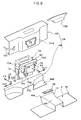
Fig. 6 is an exploded perspective view showing a structure of a seal between a cooling unit and a tunnel that constitute a vehicle front portion structure according to an embodiment of the present invention. -
Fig. 7 is an exploded perspective view showing a structure of an air guide and air exhaust with respect to a cooling unit that constitutes a vehicle front portion structure according to an embodiment of the present invention. -
Fig. 8 is an enlarged perspective view showing a mounting structure of a battery that constitutes a vehicle front portion structure according to an embodiment of the present invention. -
Fig. 9 is an exploded perspective view showing a mounting structure of a battery that constitutes a vehicle front portion structure according to an embodiment of the present invention. -
Fig. 10 is a side sectional view showing a schematic overall configuration of a vehicle to which has been applied a vehicle front portion structure according to an embodiment of the present invention. -
Fig. 11 is a figure used to explain, through a comparison with comparative examples, the effect of extending a wheel base without enlarging a vehicle of the present invention, which is achieved by a vehicle front portion structure according to an embodiment of the present invention. Therein, the upper image is a schematic side view of a vehicle according to a comparative example, the middle image is a schematic side view of a vehicle according to another comparative example, and the lower image is a schematic side view of a vehicle according to an embodiment of the present invention. -
Fig. 12 is a sectional side view schematically showing a vehicle front portion structure according to a variation of an embodiment of the present invention. -
Fig. 13 is a sectional side view schematically showing a vehicle front portion structure according to another variation of an embodiment of the present invention. - In the following, an explanation of a vehicle
front portion structure 10 according to an embodiment of the present invention is made with reference toFigs. 1-11 . A configuration of a vehicle body 11 will be explained first, followed by an explanation of a mounting structure of each part (unit) mounted at vehicle body 11. In the figures, arrow FR indicates a front direction in a vehicle front-rear direction, arrow UP indicates upwards in a vehicle vertical direction, arrow IN indicates a vehicle width direction inner side, and arrow OUT indicates a vehicle width direction outer side. -
Fig. 10 is a side sectional view showing a schematic overall configuration of a vehicle A to which has been applied vehiclefront portion structure 10.Fig. 1 is a side sectional view schematically showing vehiclefront portion structure 10, andFig. 2 is a sectional plan view schematically showing vehiclefront portion structure 10. As shown in these figures, vehicle body 11 is provided with a pair of left and rightfront side members 12 as framework members that have a length in a vehicle front-rear direction. - Vehicle front-rear direction
rear portions 12A offront side members 12 continue to a front end in a vehicle front-rear direction oftunnel side members 15 that extend in a vehicle front-rear direction along afloor tunnel 14 formed at a vehicle floor F.Front side members 12 are positioned at an outer side in a vehicle width direction with respect totunnel side members 15, andrear portions 12A offront side members 12 that are connected thereto are disposed at an angle with respect to a vehicle front-rear direction. Thereby, as shown inFig. 2 , left and rightfront side members 12 andtunnel side members 15 constitute a vehicle body framework having a substantially "Y" shape in plan view in vehiclefront portion structure 10. Further, left and righttunnel side members 15 are each fixed at a corner portion formed at an upper side offloor tunnel 14. In this way,tunnel side members 15 arranged at an upper portion offloor tunnel 14 continue in substantially a straight line in a side view with respect tofront side members 12, and a kick portion (prominent kick portion) is not formed betweentunnel side members 15 andfront side members 12. - Further, in the present embodiment,
front side members 12 include forkingportions 12B that fork towards a vehicle outer side with respect torear portions 12A. Forkingportions 12B continue to a front end in a vehicle front-rear direction ofrockers 16 which are framework members of that extend in a vehicle front-rear direction at outer ends in a vehicle width direction of vehicle body 11. As shown inFigs. 2 and8 , front ends ofrockers 16 are connected to lower ends in a vehicle vertical direction offront pillars 18 which are framework members that extend in a vehicle vertical direction. - As shown in
Fig. 1 , in vehicle body 11, rear ends in a vehicle front-rear direction offloor tunnel 14 andtunnel side members 15 are fixed to a vehicle front surface of across member 20, which extends in a vehicle width direction and is connected to left andright rockers 16.Cross member 20 is a framework member for supporting afront seat 22 of vehicle body 11. As a result, vehicle body 11 has a configuration in whichfloor tunnel 14 is not above vehicle floor F to the rear ofcross member 20, and each portion in a vehicle width direction of floor F forrear seat 24 is configured to be low and flat. - Between
front ends 12C in a vehicle front-rear direction of left and rightfront side members 12 spans abumper reinforcement 28 as a bumper framework member that constitutes afront bumper 26 that extends in a vehicle width direction. As shown inFig. 4A , infront bumper 26,bumper reinforcement 28 is covered at a vehicle front side by afront bumper cover 30, and betweenbumper reinforcement 28 andfront bumper cover 30 is arranged anabsorber 32. In the present embodiment, acrash box 68 described below is provided betweenbumper reinforcement 28 and eachfront end 12C offront side members 12. - According to the above, in vehicle body 11, in a frontal impact, a load is transmitted mainly towards a vehicle front-rear direction rear portion via
bumper reinforcement 28,front side members 12,tunnel side members 15 androckers 16. Further, although not shown in the drawings, under a floor at a rear portion of vehicle body 11, a framework member (other than rockers 16), for transmitting a load which has been transmitted fromtunnel side members 15 to crossmember 20 to a rear in a vehicle front-rear direction, extends in a vehicle front-rear direction. - As shown in
Fig. 1 , in vehicle body 11, an engine room E which is a vehicle front portion space in which is arranged apower unit 50, anair conditioning unit 72, a coolingunit 74, which are each described below, and the like, is formed rearward in a vehicle front-rear direction with respect tobumper reinforcement 28. A rear end in a vehicle front-rear direction of engine room E is defined by adash panel 34 that partitions engine room E and a cabin C. As shown inFigs. 2 and8 ,dash panel 34 spans the entire width between left and rightfront pillars 18, and extends in a vehicle vertical direction. As shown inFig. 1 , at an upper end in a vehicle vertical direction ofdash panel 34 is connected acowl reinforcement 36 that constitutes a cowl.Cowl reinforcement 36 is fixed to and thereby supports a lower end in a vehicle vertical direction of a windshield glass WS. -
Dash panel 34 is covered by aninstrument panel 38 from a cabin C side.Instrument panel 38 forms instrument panel space I, at which abattery 76 is arranged betweeninstrument panel 38 and dashpanel 34. As shown inFig. 8 , aninstrument panel reinforcement 40 which is a framework member that spans between left and rightfront pillars 18 is arranged at instrument panel space I. Although not shown in the drawings, part of a steering device, various airbag devices and the like are arranged in instrument panel space I. - As shown in
Figs. 5 ,8 and9 , awindow portion 42 for accessing instrument panel space I from an engine room E side is formed indash panel 34. In the present embodiment,window portion 42 is formed in substantially a "T" shape when viewed from the rear, at a projecting portion 34A which projects towards a rear in a vehicle front-rear direction at a center portion in a vehicle width direction ofdash panel 34. - Further, as shown in
Figs. 8 and9 , at a lower portion in a vehicle vertical direction ofdash panel 34 is connected a front end portion in a vehicle front-rear direction of afloor panel 44 at which is formedfloor tunnel 14. Specifically,dash panel 34 includes afloor connection portion 34B connected to a general portion (other than floor tunnel 14) offloor panel 44, and atunnel connection portion 34C connected tofloor tunnel 14.Tunnel connection portion 34C is superposed onfloor tunnel 14 in a vehicle vertical direction, and thereby, as shown inFig. 5 , an openingend 14A that opens towards a vehicle front direction is positioned in engine room E. - As shown in
Fig. 9 ,dash panel 34 explained above is configured by connecting anupper dash panel 46 to alower dash panel 48.Upper dash panel 46 includes a projecting portion 34A (window portion 42) andlower dash panel 48 includesfloor connection portion 34B andtunnel connection portion 34C. InFig. 8 ,upper dash panel 46 is removed, andwindow portion 42 is indicated with a two-dot chain line. - Vehicle A is provided with
power unit 50 for generating running driving force. As shown inFigs. 2 and3 ,power unit 50 is provided with anengine 52 which is an internal combustion engine and anelectric motor 54 as drive sources Thus, vehicle A is a hybrid vehicle with two drive sources. Specifically,power unit 50 includes asmain elements engine 52 andtransaxle 56 which is connected toengine 52 such that it can transmit power thereto.Transaxle 56 includeselectric motor 54, a generator, a power split device r, a transmission such as a continuously variable transmission (each not shown) and the like. Further, in the present embodiment,transaxle 56 includes an inverter electrically connected toelectric motor 54, generator and abattery 76 which is described below. Thus,power unit 50 according to the present embodiment may be thought of as a power plant. - As shown in
Fig. 2 , adrive shaft 58, which is an output shaft ofpower unit 50, is connected to afront wheels 60 such that it may transmit driving force thereto. Eachfront wheel 60 is connected to atie rod 62 that constitutes a steering device such that it may be turned by steering a steering wheel. - As shown in
Figs. 1-3 ,power unit 50 is arranged near the rear ofbumper reinforcement 28 in a vehicle front-rear direction. In other words, in vehiclefront portion structure 10, a radiator or an air conditioner condenser, which are provided in a normal vehicle, are not provided betweenbumper reinforcement 28 andpower unit 50. In vehiclefront portion structure 10,power unit 50 is provided near tobumper reinforcement 28 utilizing a space obtained by not providing the radiator or air conditioner condenser thereat. - Further, as shown in
Fig. 3 , in vehiclefront portion structure 10,power unit 50 is supported by vehicle body 11 viafront side members 12 andbumper reinforcement 28. Specifically,power unit 50 is supported elastically near front ends 12C at left and rightfront side members 12 via left and right engine mounts 64. Eachengine mount 64 is a member in which rubber is filled between a metal inner tube and a metal outer tube, along a common axial direction of the tubes. Eachengine mount 64 may have an outer tube fixed tofront side members 12 and an inner tube fixed topower unit 50, thereby elastically supportingpower unit 50 atfront side members 12. - A vehicle front side portion of
power unit 50 and a rear surface ofbumper reinforcement 28 are connected via aconnection members 66. Eachconnection member 66 is removably connected to at least one ofpower unit 50 orbumper reinforcement 28 by fastening using a bolt and nut (not shown) or the like. Between each left and rightfront side member 12 andbumper reinforcement 28 is provided acrash box 68.Crash box 68 is configured to absorb a load (impact energy), which is above a predetermined value and is input from a vehicle front, by being axially compressed and crushed in a vehicle front-rear direction. As shown inFig. 4A , in the present embodiment,rubber bushings 70 are provided betweencrash box 68 andbumper reinforcement 28. -
Rubber bushings 70 are provided so as tosandwich bumper reinforcement 28 from both sides in a vehicle vertical direction, and are supported from both sides in the vehicle vertical direction by upper and lower supportingportions 68A ofcrash boxes 68. Therefore, in the present embodiment,bumper reinforcement 28 andpower unit 50, which are connected viaconnection member 66, are supported elastically (floating support) via left and right engine mounts 64 and left andright rubber bushings 70. - As a result, in vehicle
front portion structure 10, a vibration absorbing effect, in which the transmission of vibrations frompower unit 50 to vehicle body 11 is suppressed, can be obtained. As a result, a space is formed betweenabsorber 32, which is attached tobumper reinforcement 28, andfront bumper cover 30, , and interference betweenpower unit 50 side and a vehicle body 11 side that accompanies vibration can be prevented. In a configuration in whichabsorber 32 is provided atfront bumper cover 30, a space may be configured betweenabsorber 32 andbumper reinforcement 28. - In vehicle
front portion structure 10,connection member 66 is axially compressed and crushed in a vehicle front-rear direction by a load above a predetermined value input from a vehicle front direction; thereby, it is configured to absorb a load (an impact energy). That is,connection member 66 is provided betweenbumper reinforcement 28 andpower unit 50, as a member corresponding to a crash box. As a result, in vehiclefront portion structure 10, owing toconnection member 66 andcrash box 68, the transmission of an impact load topower unit 50 supported byfront side members 12 can be suppressed. - In the present embodiment, as shown in
Fig. 1 , anexhaust pipe 52A ofengine 52 that constitutespower unit 50 extends out from a vehicle upper rear portion atengine 52, and passes throughfloor tunnel 14 to a vehicle outer side (and is connected to a muffler or the like provided at a rear portion in a vehicle front-rear direction). In the present embodiment, acatalytic converter 52B for purifying exhaust gas ofengine 52 is arranged withinfloor tunnel 14. - Mounting Structure of Air Conditioning Unit, Cooling Unit, and Battery As shown in
Figs. 1 and2 , coolingunit 74 andair conditioning unit 72 for air conditioning cabin C are provided in engine room E to the rear ofpower unit 50 in vehicle front-rear direction. Further,battery 76 is provided in instrument panel space I to the rear ofair conditioning unit 72 for air conditioning in a vehicle front-rear direction. -
Air conditioning unit 72 is configured by accommodating, in an air conditioning case, devices for air conditioning of a vehicle, such as an evaporator for refrigeration that constitutes a refrigeration cycle, a heater core for heating, a blower for blowing air, and a damper device for switching an air flow outlet. In the example shown inFig. 1 (see alsoFig. 8 ), connection states of aregister nozzle 72A, for blowing air towards a cabin occupant, and of adefroster nozzle 72B for blowing air to a windshield glass WS, are shown.Register nozzle 72A, and a foot nozzle for blowing air to the feet, a side register nozzle, and a rear seat nozzle for blowing air to a rear seat (each not shown) are each connected toair conditioning unit 72 after mountingair conditioning unit 72 to a vehicle. - Cooling
unit 74, as shown inFig. 7 , includes as main elements aheat exchange portion 74A, afan 74B for guiding cooling air to heatexchange portion 74A, and afan shroud 74C that covers each ofheat exchange portion 74A andfan 74B from peripheral edges thereof.Heat exchange portion 74A includes a radiator for coolingpower unit 50 and a condenser that constitutes a refrigeration cycle of a vehicle air conditioning device, which are each modular components. In other words,heat exchange portion 74A is configured with a heat exchanger between engine coolant water and cooling air, and a heat exchanger between air conditioning coolant medium and cooling air. - As shown in
Fig. 9 , coolingunit 74 is modular with respect to air conditioning unit 72 (air conditioning unit 72 is omitted fromFig. 7 ). In the present embodiment,air conditioning unit 72 andcooling unit 74 are connected by left andright brackets 78 such that they may be handled in an integrated manner. Although not shown in the drawings, an air conditioning condenser that constitutesheat exchange portion 74A, before mounting to a vehicle, is connected to a pipe that is part of a coolant medium circulation path ofair conditioning unit 72. As a result, although not shown in the drawings, a module that includesair conditioning unit 72 andcooling unit 74 in the present embodiment includes an expansion valve that constitutes a refrigeration cycle of a vehicle air conditioning device. Moreover, in the present embodiment, before mounting to a vehicle, wiring offan 74B is electrically connected to necessary wiring ofair conditioning unit 72. - Cooling
unit 74, which is modular with respect toair conditioning unit 72, is supported at a vehicle body as described below, andfan shroud 74C closes from a vehicle front direction an openingend 14A, which faces a vehicle front direction, offloor tunnel 14, via aseal member 80 as a seal structure (seeFig. 5 ). That is, as shown inFig. 6 , openingend 14A is configured so as to contact a peripheral edge portion offan shroud 74C viaseal member 80. - Therefore, in the present embodiment, cooling
unit 74 may expel air (cooling air) supplied to a heat exchange atheat exchange portion 74A to outside of the vehicle viafloor tunnel 14. In vehiclefront portion structure 10 as described above,tunnel side members 15 and anexhaust pipe 52A pass throughfloor tunnel 14. As a result, as shown inFig. 6 , at respective corner portions offan shroud 74C andheat exchange portion 74A,cutaway portions 74D are formed so as to allowtunnel side members 15 andexhaust pipe 52A to pass therethrough. Further,brackets 78 described above are fixed to side surfaces ofcutaway portions 74D. Thereby, by moving a module com
prisingair conditioning unit 72 andcooling unit 74 from a vehicle front to a vehicle rear, the module may be attached at a predetermined position while allowingtunnel side members 15 to pass throughcutaway portions 74D. - As shown in
Figs. 1 and5 , aduct 82 for introducing cooling air to heatexchange portion 74A is provided in vehiclefront portion structure 10.Duct 82 includes a coolingair intake port 82A at a vehicle front direction with respect to heatexchange portion 74A, that opens downward in a vehicle vertical direction, and a coolingair supply port 82B that opens facingheat exchange portion 74A. Specifically, as shown inFig. 7 which is an exploded perspective view,duct 82 is configured as above so as to push out a portion of an undercover 84, which covers engine room E from below in a vehicle vertical direction, upwards in a vehicle vertical direction. - As shown in
Figs. 5 and7 , in vehiclefront portion structure 10, aflap 86 is provided as a flow adjusting member directly below coolingunit 74.Flap 86 projects further downward in a vehicle vertical direction than undercover 84 and is a plate shaped member that faces a vehicle front.Flap 86 receives running air flow of vehicle A, and is configured such that a negative pressure portion is generated to the rear thereof in a vehicle front-rear direction (at a downstream side of an air flow). Owing to this negative pressure, the passing of cooling air throughheat exchange portion 74A can be promoted in vehiclefront portion structure 10. - Further, as shown in
Fig. 5 ,air conditioning unit 72 is provided with a coolingnozzle 88 as a cooling assisting structure for cooling coolingunit 74. Coolingnozzle 88 is provided inserted intoduct 82 and opens towards a vehicle front ofheat exchange portion 74A.Air conditioning unit 72 is configured to blow air-conditioned air which has been cooled at an evaporator if, for example, a water temperature of a radiator that constitutes coolingunit 74 exceeds a predetermined temperature. For example, if, based on a signal from a water temperature sensor, it is judged that a water temperature of a radiator has exceeded a predetermined temperature, an air-conditioning ECU as a control device that controls an operation ofair conditioning unit 72 operates (or continues to operate) a refrigeration cycle, and by opening a damper of coolingnozzle 88, air-conditioned air cooled at an evaporator is blown towardsheat exchange portion 74A. -
Battery 76 is an accumulator battery that stores electrical power for drivingelectric motor 54. Sincebattery 76 has a high density, it has sufficient charge capacity, and its dimensions are such that it may be arranged, viawindow portion 42 ofdash panel 34, at a center portion in a vehicle width direction in instrument panel space I. As shown inFig. 5 ,battery 76 is arranged at a vehicle front-rear direction rear side ofair conditioning unit 72, and is modular with respect toair conditioning unit 72. In the present embodiment,air conditioning unit 72 andbattery 76 are modular and can be handled in an integrated manner by fixing them to each other via apartition panel 90 and arubber bushing 92. Thus, in the present embodiment, as shown inFigs. 8 and9 , three parts (units), namely,air conditioning unit 72, coolingunit 74, andbattery 76 are modular. - Moreover, as shown in
Figs. 5 ,8 and9 , atpartition panel 90 is provided abattery cooling duct 94 that coversbattery 76 and that opens downwards in a vehicle vertical direction.Battery cooling duct 94 may be formed integrated withpartition panel 90, or may be configured as a separate element (independent part) which is attached topartition panel 90. As shown inFig. 5 ,air conditioning unit 72 is provided with a batterycooling air outlet 96 that opens to an upper portion in a vehicle vertical direction ofbattery cooling duct 94. In the present embodiment,battery cooling duct 94 and batterycooling air outlet 96 correspond to a battery cooling structure of the present invention. -
Air conditioning unit 72 is configured such that if a temperature ofbattery 76 exceeds a predetermined temperature or the like, air-conditioned air cooled at an evaporator is blown from battery coolingair outlet 96. For example, if the above-described air conditioning ECU judges that a temperature ofbattery 76 has exceed a predetermined temperature based on a signal from a battery temperature sensor, it operates (or continues to operate) a refrigeration cycle, and by opening a damper of batterycooling air outlet 96, air-conditioned air cooled at an evaporator is blown tobattery 76. -
Battery 76 is accommodated within instrument panel space I viawindow portion 42 ofdash panel 34 together withbattery cooling duct 94. Thereby, of themodules battery 76,air conditioning unit 72, and coolingunit 74,battery 76 is arranged in instrument panel space I, andair conditioning unit 72 andcooling unit 74 are arranged in engine room E.Air conditioning unit 72 is arranged at an engine room E side by inserting it into projecting portion 34A ofdash panel 34. - As shown in
Figs. 5 and8 ,window portion 42 ofdash panel 34 is closed bypartition panel 90.Partition panel 90 is fixed to dashpanel 34 at multiple locations of a peripheral edge ofwindow portion 42 ofdash panel 34, thereby closingwindow portion 42. In the present embodiment,partition panel 90 may be fixed to dashpanel 34 by fastening such that it may be removed therefrom, and may be taken off during maintenance or the like. -
Battery 76 is supported abovefloor tunnel 14 by abattery mounting bracket 98.Battery mounting bracket 98 has a length in a vehicle width direction, and has a hat shape that opens downwards in a vehicle vertical direction, when seen in a section taken along a direction perpendicular to the length direction. Aflange 98A that extends from an edge of the opening ofbattery mounting bracket 98 is welded to anupper surface 14B offloor tunnel 14, and therebybattery mounting bracket 98 forms a closed section structure withfloor tunnel 14.Battery 76 is fastened tobattery mounting bracket 98 at multiple locations (two locations in the example shown inFig. 9 ) separated in a length direction, and is thereby supported elastically viarubber bushing 92. -
Modules battery 76,air conditioning unit 72 andcooling unit 74 are fixed to dashpanel 34 ofpartition panel 90, and are supported elastically bybattery mounting bracket 98 ofbattery 76, and are thereby supported overall by vehicle body 11. Considering onlybattery 76 alone, it may be thought of as being elastically supported (floating support) by vehicle body 11 viarubber bushing 92 at apartition panel 90 side andrubber bushing 92 at abattery mounting bracket 98 side. - The above-described
battery 76 is electrically connected to (an inverter for)electric motor 54 via ahigh voltage cable 100, as shown inFig. 8 .High voltage cable 100 passes through a cable through-hole (not shown) formed in dash panel 34 (upper dash panel 46) and is led into engine room E from instrument panel space I. - The following describes the operation of the present embodiment.
- As shown in
Fig. 1 , in vehiclefront portion structure 10 having the above configuration,power unit 50 is arranged directly behindbumper reinforcement 28, namely at a front end portion in a vehicle front-rear direction within engine room E. In other words, in vehiclefront portion structure 10,power unit 50 is arranged further to a vehicle front compared to a comparative example in which a radiator and an air conditioner condenser are arranged at a front end portion in a vehicle front-rear direction within engine room E (power unit 50 is moved towards the front). As a result, in vehiclefront portion structure 10, it is possible to providefront wheel 60 towards a vehicle front together withpower unit 50, and thereby lengthen a wheel base without enlarging vehicle body 11. With this configuration, vehiclefront portion structure 10 contributes to the effective lightening of the entirety of vehicle A by lightening vehicle body 11. - Further explanation of this point is given in the following. If a vehicle body is lightened by, for example, altering the material of a body outer plate (such as by making it of high-tensile steel or a resin), or by lightening an internal material,
power unit 50 becomes comparatively heavier. As a result, as indicated by the upper image showing a comparative example inFig. 11 , ifonly vehicle body 200 is lightened, the load distribution balance betweenfront wheel 60 andrear wheel 102 becomes unbalanced. Specifically, the proportion of load distribution borne byfront wheel 60 increases, and it becomes necessary to lengthen the wheel base. As shown in the center image ofFig. 11 , in order to lengthen a wheel base (see arrow A), avehicle body 210 is lengthened to the rear in a vehicle front-rear direction compared to vehicle body 200 (see arrow B), and since this enlarges the vehicle body, the effect of lightening the vehicle body is reduced. - As shown schematically in the lower image of
Fig. 11 , vehiclefront portion structure 10 has a configuration in which a wheel base is lengthened by movingpower unit 50 towards a vehicle front. As a result, it is possible to realize a vehicle body 11 which is not lengthened compared tovehicle body 200, but which has a lengthened wheel base (see arrow C) compared tovehicle body 200. By lengthening the wheel base in a configuration in which a lightened vehicle body 11 is used, it is possible to obtain a favorable load distribution balance between front and rear wheels. Therefore, as described above, vehiclefront portion structure 10 contributes to the effective lightening of the entirety of vehicle A by lightening vehicle body 11. - Further, in vehicle
front portion structure 10, compared to the above describedvehicle body 200 andvehicle body 210,front wheel 60 is moved further towards a vehicle front, and therefore a front overhang is shortened. This contributes to improved maneuverability and treatment performance to vehicle A. Further, in vehiclefront portion structure 10, sincepower unit 50 is arranged at a front end portion in a vehicle front-rear direction of engine room E, it is possible to dispense with a support member or the like at eachfront end 12C offront side members 12 for supporting a radiator or air conditioning condenser. Moreover, in vehiclefront portion structure 10, sinceair conditioning unit 72 is arranged to the rear ofpower unit 50 in a vehicle front-rear direction and between the front and rear wheels, a weight balance of vehicle A is improved, thereby contributing to a substantial improvement in maneuverability. - Moreover, in vehicle
front portion structure 10,power unit 50 is supported byfront side members 12 andbumper reinforcement 28. As a result, it is possible to attachbumper reinforcement 28 andpower unit 50, which are connected byconnection member 66, tofront side members 12 as a module from a vehicle front. Thereby, an operation of lifting up vehicle body 11 in order to attachpower unit 50 or the like becomes unnecessary, and the manufacturability and maintenance properties of vehicle A can be improved. - In vehicle
front portion structure 10,power unit 50 is arranged at a front end portion in a vehicle front-rear direction of engine room E. Thereby, in a frontal collision of vehicle A, the movement ofpower unit 50, which has a large inertial mass, towards a front in a vehicle front-rear direction can be quickly stopped. - In vehicle
front portion structure 10,power unit 50 is arranged at a front end portion in a vehicle front-rear direction of engine room E. Thereby, a configuration can be realized in whichtunnel side members 15 that are arranged infloor tunnel 14 andfront side members 12 are connected. As a result, in a frontal collision of vehicle A, a load is transmitted to a rear in a vehicle front-rear direction viafront side members 12 andtunnel side members 15. In other words, near a center of gravity G of vehicle A (seeFig. 10 ), a load is transmitted towards the rear. Consequently, a necessary strength offront side members 12 andtunnel side members 15 to resist bending due to a front impact load can be reduced. - In a standard framework configuration in which a front side member and a side member under a floor are connected by a kick portion that inclines with respect to a vehicle vertical direction, an impact load is supported at the side member under the floor, which is greatly separated downwards in a vehicle vertical direction from a load input point (near center of gravity G in a vehicle vertical direction) of the front side member. As a result, the above-mentioned necessary strength to resist the bending of the kick portion increases, and as a result an excessive amount of reinforcement must be provided with respect to other requirements. Consequently, the weight of vehicle body 11 increases in this comparative example.
- In contrast, in vehicle
front portion structure 10, owing to the above configuration in whichfront side members 12 are connected totunnel side members 15, which do not pass under a floor, the above-mentioned necessary strength to resist bending of the kick portion decreases, thereby contributing to the lightening of vehicle body 11. - Effect of Arranging a Cooling Unit and Air Conditioning Unit In vehicle
front portion structure 10, in whichpower unit 50 is arranged at a front end portion in a vehicle front-rear direction of engine room E as described above, there is greater freedom to arrange other parts such asair conditioning unit 72 andcooling unit 74. In vehiclefront portion structure 10,air conditioning unit 72 andcooling unit 74 are arranged in engine room E to the rear ofpower unit 50 in a vehicle front-rear direction. Thereby, it is possible to makeair conditioning unit 72 andcooling unit 74 modular. By makingair conditioning unit 72 andcooling unit 74 modular, they can be attached as an integrated element. Consequently, the attachability ofair conditioning unit 72 andcooling unit 74 with respect to vehicle body 11 can be improved. - In vehicle
front portion structure 10, by makingair conditioning unit 72 andcooling unit 74 modular, wiring and piping can be connected before mounting to a vehicle. As a result, it is possible to reduce wiring and piping operations performed after mounting to a vehicle, and this also improves attachability ofair conditioning unit 72 andcooling unit 74 with respect to vehicle body 11. - Moreover, in vehicle
front portion structure 10, coolingnozzle 88 is provided for supplying air-conditioned air fromair conditioning unit 72 to heatexchange portion 74A of coolingunit 74. As a result, by using air conditioned air fromair conditioning unit 72, cooling ofcooling unit 74 can be promoted. Specifically, when a water temperature of a radiator that constitutesheat exchange portion 74A is high, cooling of cooling water at a radiator can be promoted by air-conditioned air cooled at an evaporator. - In this way, in vehicle
front portion structure 10, in special environments in which a water temperature of a radiator increases (such as in traffic congestion in the summer, or long hill climbing), by usingair conditioning unit 72, cooling performance of a radiator can be improved. Thereby, in vehiclefront portion structure 10, it is not necessary to ensure favorable cooling performance in special environments only via an air flow obtained by a running air flow or via the operation offan 74B. Consequently, in vehiclefront portion structure 10, it is possible to realize a reduction in the size of a radiator, and an optimal specification ofheat exchange portion 74A which includes the radiator. As a result, a circulation amount of coolant water may be reduced, and fuel efficiency during normal running can be improved. - In vehicle
front portion structure 10, as shown inFig. 1 , during the running of vehicle A, air introduced from a lower portion (under a floor) of undercover 84 is supplied via coolingair intake port 82A ofduct 82 to a heat exchange atheat exchange portion 74A.
This air passes throughheat exchange portion 74A due to a negative pressure that is generated at flap 86 (and due to the operation offan 74B), flows intofloor tunnel 14, passes throughfloor tunnel 14 and is smoothly expelled to under floor F. Thereby, efficient heat exchange atheat exchange portion 74A can be achieved using an air flow under the floor andfloor tunnel 14. - In a comparative example in which a cooling unit comprising a radiator and an air conditioning condenser is arranged at a frontmost portion in engine room E, an engine is arranged at the rear of the cooling unit in a vehicle front-rear direction. As a result, a flow of cooled air that has passed through the cooling unit is blocked by the engine and cannot flow smoothly through engine room E. Further, in this comparative example, an opening for introducing the cooling air flow to the cooling unit must be formed in a bumper cover, and therefore a large air resistance is generated, especially at high speeds. In particular, in hybrid vehicles or the like, in which little heat is generated from an engine, although the performance requirements of a radiator are reduced, if a cooling unit that includes a radiator is arranged as in the above-described comparative example, fuel efficiency becomes comparatively worse due to air flow resistance.
- In contrast, in vehicle
front portion structure 10, a cooling air flow is taken in fromduct 82 of undercover 84, so there is no need to form an opening for taking in air infront bumper cover 30. Further, sinceseal member 80 seals between openingend 14A offloor tunnel 14 andcooling unit 74, it is possible to expel air guided fromduct 82 smoothly throughfloor tunnel 14 which has little air flow resistance. Moreover, due to a negative pressure at the rear ofheat exchange portion 74A in a vehicle front-rear direction generated byflap 86, the passage of an air flow guided fromduct 82 throughheat exchange portion 74A, in other words, a heat exchange atheat exchange portion 74A, is promoted. As a result, in vehiclefront portion structure 10, it is possible to suppress disruption of an air flow around vehicle A accompanying with the running of vehicle A, to promote heat exchange at coolingunit 74, and to simultaneously improve the aerodynamic performance (fuel efficiency) of vehicle A and the cooling performance ofair conditioning unit 72. - In vehicle
front portion structure 10, sinceseal member 80 seals between openingend 14A offloor tunnel 14 andcooling unit 74, heated air which is heated atpower unit 50 is prevented from moving to withinfloor tunnel 14, and thereby a reduction in performance of coolingunit 74 due to the heated air can be prevented. - In vehicle A, which is a hybrid vehicle in which
power unit 50 generates little heat as explained above, by arrangingair conditioning unit 72 to the rear ofpower unit 50 in a vehicle front-rear direction, it is possible to warm the engine quickly at the initial stage of a cold start. This contributes to improved fuel efficiency at the initial stage of a cold start. - In vehicle
front portion structure 10,battery 76, which, as explained above, has a sufficient capacity while having a small size, is arranged at a center portion in a vehicle width direction in instrument panel space I. Thereby,battery 76, which is comparatively heavy, can be arranged closer to center of gravity G of vehicle A, and it is possible to reduce a yaw moment of inertia. As a result, it is possible to increase running stability of vehicle A. Moreover, in vehiclefront portion structure 10, sincewindow portion 42 is formed indash panel 34, it is possible to makeair conditioning unit 72, which is arranged in engine room E, andbattery 76, which is arranged in instrument panel space I, modular. - By making
air conditioning unit 72 andbattery 76 modular, they can be attached to a vehicle body in an integrated manner. Accordingly, the attachability ofair conditioning unit 72 andbattery 76 to vehicle body 11 is improved. In particular, in vehiclefront portion structure 10, since coolingunit 74 is also made modular,air conditioning unit 72, coolingunit 74, andbattery 76 each has high attachability. - In vehicle
front portion structure 10, owing tobattery cooling duct 94 andbattery cooling outlet 96, when a temperature ofbattery 76 is high, air-conditioned air ofair conditioning unit 72 can be used to perform a forced cooling ofbattery 76. This prevents overheating ofbattery 76 and contributes to improved performance and endurance ofbattery 76. - Further, in vehicle
front portion structure 10, sincewindow portion 42 is formed indash panel 34,battery 76 can be attached within instrument panel space I from an engine room E side. As a result, in vehiclefront portion structure 10, it is possible to attach or removebattery 76 without taking offinstrument panel 38 or the like, and therefore the attachability and maintenance properties ofbattery 76 are high. - Moreover, in vehicle
front portion structure 10, sincebattery 76 is elastically supported with respect topartition panel 90 andbattery mounting bracket 98 viarubber bushing 92, owing to a damping effect ofrubber bushing 92, it is possible to suppress (block) transmission of a vibration tobattery 76. - In the above embodiment, explanation is given of an example in which
exhaust pipe 52A ofengine 52 exits from a rear side in a vehicle front-rear direction. However, the present invention is not limited to this, and may include a configuration, for example, in whichexhaust pipe 52A exits from a front side in a vehicle front-rear direction ofengine 52, as shown inFig. 12 . In this variation,catalytic converter 52B is disposed in front ofengine 52, and has a length direction in a vehicle width direction, andexhaust pipe 52A ofengine 52 is led under the floor and towards a rear in a vehicle front-rear direction (since this portion is a common configuration, it is omitted in the drawings). Owing to this embodiment, sinceexhaust pipe 52A andcatalytic converter 52B are not provided withinfloor tunnel 14, an air flow that accompanies a cooling ofair conditioning unit 72 can be made even smoother. - In the above embodiment, an example is given in which
floor tunnel 14 is provided up to crossmember 20 forfront seat 22. However, the present invention is not limited to this, and may include a configuration, for example, in whichfloor tunnel 14 passes through a center in a vehicle width direction of a rear seat, as shown inFig. 13 . In this variation,tunnel side members 15 extend up to a rear side in a vehicle front-rear direction, andtunnel side members 15 can therefore be provided closer to a center of gravity G of vehicle A in a vehicle vertical direction. As a result, a strength necessary to resist bending in a frontal impact can be further reduced, which contributes to increased lightening of vehicle body 11. In the example shown inFig. 13 ,tunnel side members 15 contact across member 104 at a rear portion in a vehicle front-rear direction. - In the above embodiment, an example is given in which
power unit 50 is provided with bothengine 52, which is an internal combustion engine, andelectric motor 54, as power sources. However, the present invention is not limited to this, and may include a configuration, for example, in whichpower unit 50 includes only one ofengine 52 orelectric motor 54 as a power source. In a configuration in which onlyengine 52 is provided aspower unit 50, a configuration may be adopted, for example, in which an electric motor as a drive source is disposed at a rear portion in a vehicle front-rear direction, or disposed within a vehicle wheel. - Further, in the above embodiment, an example is given in which, cooled air obtained by
air conditioning unit 72 is used as a cooling assisting structure and a battery cooling structure. However, the present invention is not limited to this, and may include a configuration, for example, in which water in a liquid phase obtained by a dehumidifying function ofair conditioning unit 72 may be applied as drops or mist to coolingunit 74 orbattery 76. In this configuration, it is possible to obtain a large cooling effect owing to the evaporation of moisture. - The present invention is not limited by the above-described embodiments, and may be implemented by modification thereof in various ways providing these do not exceed the gist of the invention.
Claims (9)
- A vehicle front portion structure comprising:a framework member of a front bumper;a power unit provided rearward in a vehicle front-rear direction with respect to the framework member, that drives at least a front wheel of a vehicle, anda cooling unit provided rearward in a vehicle front-rear direction with respect to the power unit and at a vehicle front with respect to a dash panel, and comprising at least one of a heat exchanger that is part of a cooling system of the power unit or a condenser of an air conditioning device.
- The vehicle front portion structure of claim 1, further comprising an air conditioning unit for air conditioning a vehicle cabin, which is provided at a vehicle front with respect to the dash panel and is modular such that it can be handled in an integrated manner with the cooling unit.
- The vehicle front portion structure of claim 2, wherein the air conditioning unit includes a cooling assistance structure for assisting a cooling function of the cooling unit.
- The vehicle front portion structure of any one of claim 1 to claim 3, further comprising:an air conditioning unit for air conditioning a vehicle cabin, which is provided at a vehicle front with respect to the dash panel;an electric motor that forms at least a part of the power unit, or an electric motor that is provided independently of the power unit and that generates a driving force for running a vehicle, anda battery which is modular such that it can be handled in an integrated manner with the air conditioning unit, and which stores electricity supplied to the electric motor.
- The vehicle front portion structure of claim 4, wherein a module comprising the battery and the cooling unit is inserted from a vehicle front side through an opening portion provided at the dash panel, and is detachably supported with respect to the dash panel, and at least a portion of the battery is positioned rearward in a vehicle front-rear direction with respect to the dash panel.
- The vehicle front portion structure of claim 4 or claim 5, wherein the air conditioning unit comprises a battery cooling structure for cooling the battery.
- The vehicle front portion structure of any one of claim 1 to claim 6, wherein:the cooling unit is positioned at a vehicle front with respect to a floor tunnel that opens at a lower portion in a vehicle vertical direction of the dash panel; andthe vehicle front portion structure further comprises a seal structure that seals a space between a peripheral edge portion not including a lower edge in a vehicle vertical direction of the cooling unit, and an opening edge portion of the floor tunnel.
- The vehicle front portion structure of claim 7, further comprising a flow adjusting member provided below the cooling unit in a vehicle vertical direction, for generating negative pressure rearward in a vehicle front-rear direction with respect to the cooling unit in conjunction with running of a vehicle.
- The vehicle front portion structure of claim 8, further comprising a duct structure for guiding air from an air intake portion, which opens downwards in a vehicle vertical direction at a vehicle front with respect to the cooling unit, to the cooling unit.
Applications Claiming Priority (1)
| Application Number | Priority Date | Filing Date | Title |
|---|---|---|---|
| PCT/JP2009/053281 WO2010097890A1 (en) | 2009-02-24 | 2009-02-24 | Vehicle front structure |
Publications (3)
| Publication Number | Publication Date |
|---|---|
| EP2402197A1 true EP2402197A1 (en) | 2012-01-04 |
| EP2402197A4 EP2402197A4 (en) | 2012-10-03 |
| EP2402197B1 EP2402197B1 (en) | 2013-10-02 |
Family
ID=42665116
Family Applications (1)
| Application Number | Title | Priority Date | Filing Date |
|---|---|---|---|
| EP09840744.8A Not-in-force EP2402197B1 (en) | 2009-02-24 | 2009-02-24 | Vehicle front structure |
Country Status (5)
| Country | Link |
|---|---|
| US (1) | US8672067B2 (en) |
| EP (1) | EP2402197B1 (en) |
| JP (1) | JP5018961B2 (en) |
| CN (1) | CN102317099A (en) |
| WO (1) | WO2010097890A1 (en) |
Cited By (1)
| Publication number | Priority date | Publication date | Assignee | Title |
|---|---|---|---|---|
| US11167621B2 (en) | 2016-09-26 | 2021-11-09 | Bayerische Motoren Werke Aktiengesellschaft | Retention arrangement of a refrigerant compressor on a bodywork of a motor vehicle, and a motor vehicle |
Families Citing this family (71)
| Publication number | Priority date | Publication date | Assignee | Title |
|---|---|---|---|---|
| US9188086B2 (en) | 2008-01-07 | 2015-11-17 | Mcalister Technologies, Llc | Coupled thermochemical reactors and engines, and associated systems and methods |
| US8318131B2 (en) | 2008-01-07 | 2012-11-27 | Mcalister Technologies, Llc | Chemical processes and reactors for efficiently producing hydrogen fuels and structural materials, and associated systems and methods |
| US8441361B2 (en) | 2010-02-13 | 2013-05-14 | Mcallister Technologies, Llc | Methods and apparatuses for detection of properties of fluid conveyance systems |
| CN102317099A (en) | 2009-02-24 | 2012-01-11 | 丰田自动车株式会社 | Vehicle front portion structure |
| RU2489272C1 (en) * | 2009-07-28 | 2013-08-10 | Хонда Мотор Ко., Лтд. | Mount for automotive drive motor electronic component |
| JP4957768B2 (en) * | 2009-09-02 | 2012-06-20 | トヨタ自動車株式会社 | Cooling air introduction structure |
| GB2476279B (en) * | 2009-12-17 | 2016-05-25 | Gordon Murray Design Ltd | Vehicle comprising a rearwardly mounted engine and radiator |
| US8336657B2 (en) * | 2010-02-12 | 2012-12-25 | Ford Global Technologies, Llc | Support structure for inverter system controller module |
| CN102844266A (en) | 2010-02-13 | 2012-12-26 | 麦卡利斯特技术有限责任公司 | Chemical processes and reactors for efficiently producing hydrogen fuels and structural materials, and associated systems and methods |
| JP5601858B2 (en) * | 2010-03-25 | 2014-10-08 | 三菱重工業株式会社 | Air conditioner for vehicles |
| WO2011151917A1 (en) * | 2010-06-03 | 2011-12-08 | トヨタ自動車株式会社 | Cooling-wind introduction structure |
| EP2602143B1 (en) | 2010-08-03 | 2014-05-14 | Toyota Jidosha Kabushiki Kaisha | Cooling structure for vehicles |
| JP5561156B2 (en) * | 2010-12-28 | 2014-07-30 | マツダ株式会社 | Electric vehicle |
| US20140069604A1 (en) * | 2011-05-11 | 2014-03-13 | Toyota Jidosha Kabushiki Kaisha | Vehicle heat exchange structure |
| US8734546B2 (en) | 2011-08-12 | 2014-05-27 | Mcalister Technologies, Llc | Geothermal energization of a non-combustion chemical reactor and associated systems and methods |
| WO2013025650A1 (en) | 2011-08-12 | 2013-02-21 | Mcalister Technologies, Llc | Mobile transport platforms for producing hydrogen and structural materials and associated systems and methods |
| US8911703B2 (en) | 2011-08-12 | 2014-12-16 | Mcalister Technologies, Llc | Reducing and/or harvesting drag energy from transport vehicles, including for chemical reactors, and associated systems and methods |
| WO2013025655A2 (en) | 2011-08-12 | 2013-02-21 | Mcalister Technologies, Llc | Systems and methods for providing supplemental aqueous thermal energy |
| WO2013025659A1 (en) * | 2011-08-12 | 2013-02-21 | Mcalister Technologies, Llc | Reducing and/or harvesting drag energy from transport vehicles, includings for chemical reactors, and associated systems and methods |
| EP2742207A4 (en) | 2011-08-12 | 2016-06-29 | Mcalister Technologies Llc | Systems and methods for extracting and processing gases from submerged sources |
| US9188052B2 (en) | 2011-10-12 | 2015-11-17 | Toyota Jidosha Kabushiki Kaisha | Vehicle front portion structure |
| JP2013086660A (en) * | 2011-10-18 | 2013-05-13 | Toyota Motor Corp | Vehicle front structure |
| WO2013073262A1 (en) | 2011-11-15 | 2013-05-23 | トヨタ自動車株式会社 | Cooling airflow introduction structure |
| JP5667964B2 (en) * | 2011-11-28 | 2015-02-12 | 本田技研工業株式会社 | Vehicle cable arrangement structure and vehicle assembly method |
| WO2013080339A1 (en) * | 2011-11-30 | 2013-06-06 | トヨタ自動車株式会社 | Structure for front part of vehicle |
| CN103998271A (en) * | 2011-12-16 | 2014-08-20 | 丰田自动车株式会社 | Vehicle front structure |
| DE102012001459A1 (en) * | 2012-01-25 | 2013-07-25 | Volkswagen Aktiengesellschaft | Device for cooling heat generating element in operating chamber of motor vehicle by flow of fluid, comprises heat exchanger with fluid flow machine, which is arranged downstream such that outflow of fluid strikes on heat generating element |
| JP5780176B2 (en) * | 2012-02-21 | 2015-09-16 | トヨタ自動車株式会社 | Ventilation structure for vehicles |
| JP2013180614A (en) * | 2012-02-29 | 2013-09-12 | Toyota Motor Corp | Vehicle battery temperature control structure |
| JP5278620B1 (en) * | 2012-03-01 | 2013-09-04 | トヨタ自動車株式会社 | Vehicle front structure |
| US20130248141A1 (en) * | 2012-03-26 | 2013-09-26 | Honda Motor Co., Ltd. | Ducting arrangement and method for directing airflow toward a radiator |
| WO2013161010A1 (en) | 2012-04-24 | 2013-10-31 | トヨタ自動車株式会社 | Cooling device for vehicle |
| WO2014049640A1 (en) * | 2012-09-26 | 2014-04-03 | 川崎重工業株式会社 | Electric vehicle |
| JP2014094650A (en) * | 2012-11-08 | 2014-05-22 | Toyota Motor Corp | Vehicle body front structure |
| US8926719B2 (en) | 2013-03-14 | 2015-01-06 | Mcalister Technologies, Llc | Method and apparatus for generating hydrogen from metal |
| JP6164568B2 (en) * | 2013-09-30 | 2017-07-19 | スズキ株式会社 | Exhaust system heat exchanger layout |
| JP2016048156A (en) * | 2014-08-28 | 2016-04-07 | 株式会社デンソー | Ejector type refrigeration cycle |
| US20160361991A1 (en) * | 2015-06-12 | 2016-12-15 | Ford Global Technologies, Llc | Underbody air and thermal management system for a motor vehicle |
| US20170106740A1 (en) * | 2015-10-14 | 2017-04-20 | Denso International America, Inc. | Heat exchanger for vehicle and heat exchanging system having the same |
| KR101776497B1 (en) * | 2016-05-10 | 2017-09-08 | 현대자동차주식회사 | Individual air conditioning apparaus for vehicle and method of controlling the same |
| US9855914B1 (en) * | 2016-07-08 | 2018-01-02 | Toyota Motor Engineering & Manufacturing North America, Inc. | Deformable energy absorber structures for front hood assemblies of vehicles |
| DE102016219035A1 (en) * | 2016-09-30 | 2018-04-05 | Ford Global Technologies, Llc | Automotive underbody paneling with air intake |
| CN108340770B (en) * | 2017-01-23 | 2021-12-17 | 长城汽车股份有限公司 | Cooling system and vehicle |
| JP6631565B2 (en) * | 2017-03-08 | 2020-01-15 | トヨタ自動車株式会社 | Vehicle duct structure |
| JP6397535B1 (en) * | 2017-04-25 | 2018-09-26 | 本田技研工業株式会社 | Body floor structure |
| US10527012B2 (en) | 2017-06-29 | 2020-01-07 | Pratt & Whitney Canada Corp. | Engine assembly with engine and cooler compartments |
| US10166859B1 (en) * | 2017-06-30 | 2019-01-01 | GM Global Technology Operations LLC | Active underbody arrangement for a vehicle |
| US10905647B2 (en) | 2017-06-30 | 2021-02-02 | The Procter & Gamble Company | Antiperspirant and deodorant compositions |
| US10882378B2 (en) * | 2017-08-18 | 2021-01-05 | Zhejiang CFMOTO Power Co., Ltd. | ATV air heat exchanger with mounting structure and linkage |
| US10710424B2 (en) | 2018-01-05 | 2020-07-14 | Byton Limited | HVAC unit placement configuration for a vehicle |
| JP6922763B2 (en) * | 2018-01-30 | 2021-08-18 | トヨタ自動車株式会社 | Vehicle undercarriage |
| JP6688825B2 (en) * | 2018-03-28 | 2020-04-28 | 本田技研工業株式会社 | vehicle |
| FR3079454B1 (en) * | 2018-03-30 | 2020-09-11 | Valeo Systemes Thermiques | AIR FLOW REGULATION DEVICE FOR AN AIR INTAKE OF A MOTOR VEHICLE |
| JP6640278B2 (en) * | 2018-05-25 | 2020-02-05 | 本田技研工業株式会社 | Body structure |
| DE102018114499B4 (en) * | 2018-06-18 | 2021-02-11 | Dr. Ing. H.C. F. Porsche Aktiengesellschaft | Motor vehicle bug |
| JP7063188B2 (en) * | 2018-08-21 | 2022-05-09 | トヨタ自動車株式会社 | Vehicle structure of electric vehicle |
| JP7070249B2 (en) * | 2018-08-28 | 2022-05-18 | トヨタ自動車株式会社 | Vehicle power unit structure |
| US11007900B2 (en) * | 2018-09-07 | 2021-05-18 | Ford Global Technologies, Llc | Battery thermal management assembly and method |
| JP7119818B2 (en) * | 2018-09-18 | 2022-08-17 | トヨタ自動車株式会社 | vehicle front structure |
| JP7280549B2 (en) * | 2018-12-26 | 2023-05-24 | マツダ株式会社 | vehicle battery cooler |
| JP7056547B2 (en) * | 2018-12-28 | 2022-04-19 | トヨタ自動車株式会社 | Hybrid vehicle |
| JP6990217B2 (en) * | 2019-07-02 | 2022-01-12 | 本田技研工業株式会社 | vehicle |
| US11326506B2 (en) | 2019-07-03 | 2022-05-10 | Ford Global Technologies, Llc | Vehicle fan shroud with integrated support structure |
| JP2021138317A (en) | 2020-03-06 | 2021-09-16 | トヨタ自動車株式会社 | Vehicle unit mounting structure |
| CN114523832B (en) * | 2020-11-19 | 2023-12-22 | 本田技研工业(中国)投资有限公司 | Battery protection device, vehicle and installation method of battery protection device |
| US11713082B2 (en) * | 2020-12-09 | 2023-08-01 | Ford Global Technologies, Llc | Vehicle frame |
| JP7329557B2 (en) * | 2021-03-30 | 2023-08-18 | 本田技研工業株式会社 | vehicle |
| CN115892236A (en) * | 2021-09-30 | 2023-04-04 | 马自达汽车株式会社 | Vehicle body structure |
| CN115892242A (en) * | 2021-09-30 | 2023-04-04 | 马自达汽车株式会社 | Body structure of electric vehicle |
| KR20230053393A (en) * | 2021-10-14 | 2023-04-21 | 현대자동차주식회사 | Integrated thermal management module for vehicle |
| KR20230054107A (en) | 2021-10-15 | 2023-04-24 | 현대자동차주식회사 | Integrated thermal management module for vehicle |
Citations (5)
| Publication number | Priority date | Publication date | Assignee | Title |
|---|---|---|---|---|
| GB711909A (en) * | 1948-10-01 | 1954-07-14 | Friedrich Nallinger | Improvements relating to the heating or heating and ventilation of motor road vehicles |
| GB2120379A (en) * | 1982-02-05 | 1983-11-30 | Audi Ag | Heating and ventilating device for the passenger compartment of a motor vehicle |
| JPH05301528A (en) * | 1992-04-25 | 1993-11-16 | Mazda Motor Corp | Ventilating device for automobile engine room |
| JPH06328931A (en) * | 1993-05-27 | 1994-11-29 | Mazda Motor Corp | Front part car body structure of vehicle |
| US20080000615A1 (en) * | 2006-06-30 | 2008-01-03 | Mitsubishi Jidosha Kogyo Kabushiki Kaisha | Coolant cooling structure |
Family Cites Families (26)
| Publication number | Priority date | Publication date | Assignee | Title |
|---|---|---|---|---|
| US2247742A (en) | 1939-01-21 | 1941-07-01 | Packard Motor Car Co | Motor vehicle |
| US2913065A (en) | 1957-01-23 | 1959-11-17 | Jr George A Lyon | Automotive cooling system |
| JPS47968Y1 (en) | 1967-03-28 | 1972-01-14 | ||
| DE3150152A1 (en) | 1981-12-18 | 1983-06-30 | Daimler-Benz Ag, 7000 Stuttgart | Spoiler for motor vehicles |
| JPS599119U (en) | 1982-07-08 | 1984-01-20 | 株式会社クボタ | Radiator air intake structure |
| JPS61146635A (en) * | 1984-12-20 | 1986-07-04 | Mazda Motor Corp | Lower chassis structure of automobile |
| DE3911349C2 (en) | 1989-04-07 | 1997-02-20 | Daimler Benz Ag | Motor vehicle with an encapsulated engine compartment |
| JPH0347284U (en) | 1989-09-18 | 1991-05-01 | ||
| JP3053852B2 (en) | 1990-09-06 | 2000-06-19 | マツダ株式会社 | Vehicle air conditioning unit installation structure |
| US5526872A (en) | 1993-10-22 | 1996-06-18 | Ford Motor Company | Airflow ejector for an automotive vehicle |
| JP3616213B2 (en) * | 1996-09-30 | 2005-02-02 | ヤンマー農機株式会社 | Agricultural machine bonnet structure |
| DE19908497C2 (en) | 1999-02-26 | 2003-03-13 | Daimler Chrysler Ag | Open vehicle |
| US6357541B1 (en) * | 1999-06-07 | 2002-03-19 | Mitsubishi Heavy Industries, Ltd. | Circulation apparatus for coolant in vehicle |
| JP2002155504A (en) | 2000-11-17 | 2002-05-31 | Sakai Heavy Ind Ltd | Rolling compaction vehicle |
| AT5483U1 (en) | 2001-07-02 | 2002-07-25 | Avl List Gmbh | SHUTTER FOR LOCKING OPENINGS |
| EP1321322A1 (en) * | 2001-12-21 | 2003-06-25 | DENSO THERMAL SYSTEMS S.p.A. | Vehicle with heat exchanger unit arranged near the passenger compartment |
| JP4062933B2 (en) | 2002-02-19 | 2008-03-19 | 株式会社デンソー | Vehicle cooling system |
| US7000726B2 (en) | 2002-04-26 | 2006-02-21 | Mazda Motor Corporation | Engine positioning structure for an automobile |
| US7185725B2 (en) * | 2003-07-07 | 2007-03-06 | Mazda Motor Corporation | Layout structure of driving device for vehicle |
| JP4563869B2 (en) | 2005-05-25 | 2010-10-13 | 本田技研工業株式会社 | Automobile intake structure |
| JP4435718B2 (en) * | 2005-06-15 | 2010-03-24 | 三菱電機株式会社 | Cooling structure of power conversion device for vehicle |
| JP4756332B2 (en) | 2005-08-19 | 2011-08-24 | マツダ株式会社 | Car battery mounting structure |
| JP4701916B2 (en) * | 2005-08-19 | 2011-06-15 | マツダ株式会社 | Car battery mounting structure |
| JP2007069651A (en) | 2005-09-05 | 2007-03-22 | Mazda Motor Corp | Vehicle body front part structure |
| CN102317099A (en) | 2009-02-24 | 2012-01-11 | 丰田自动车株式会社 | Vehicle front portion structure |
| WO2011151917A1 (en) | 2010-06-03 | 2011-12-08 | トヨタ自動車株式会社 | Cooling-wind introduction structure |
-
2009
- 2009-02-24 CN CN2009801567702A patent/CN102317099A/en active Pending
- 2009-02-24 JP JP2010513523A patent/JP5018961B2/en not_active Expired - Fee Related
- 2009-02-24 WO PCT/JP2009/053281 patent/WO2010097890A1/en active Application Filing
- 2009-02-24 EP EP09840744.8A patent/EP2402197B1/en not_active Not-in-force
- 2009-02-24 US US13/145,975 patent/US8672067B2/en active Active
Patent Citations (5)
| Publication number | Priority date | Publication date | Assignee | Title |
|---|---|---|---|---|
| GB711909A (en) * | 1948-10-01 | 1954-07-14 | Friedrich Nallinger | Improvements relating to the heating or heating and ventilation of motor road vehicles |
| GB2120379A (en) * | 1982-02-05 | 1983-11-30 | Audi Ag | Heating and ventilating device for the passenger compartment of a motor vehicle |
| JPH05301528A (en) * | 1992-04-25 | 1993-11-16 | Mazda Motor Corp | Ventilating device for automobile engine room |
| JPH06328931A (en) * | 1993-05-27 | 1994-11-29 | Mazda Motor Corp | Front part car body structure of vehicle |
| US20080000615A1 (en) * | 2006-06-30 | 2008-01-03 | Mitsubishi Jidosha Kogyo Kabushiki Kaisha | Coolant cooling structure |
Non-Patent Citations (1)
| Title |
|---|
| See also references of WO2010097890A1 * |
Cited By (1)
| Publication number | Priority date | Publication date | Assignee | Title |
|---|---|---|---|---|
| US11167621B2 (en) | 2016-09-26 | 2021-11-09 | Bayerische Motoren Werke Aktiengesellschaft | Retention arrangement of a refrigerant compressor on a bodywork of a motor vehicle, and a motor vehicle |
Also Published As
| Publication number | Publication date |
|---|---|
| WO2010097890A1 (en) | 2010-09-02 |
| US8672067B2 (en) | 2014-03-18 |
| US20110284298A1 (en) | 2011-11-24 |
| JP5018961B2 (en) | 2012-09-05 |
| EP2402197B1 (en) | 2013-10-02 |
| CN102317099A (en) | 2012-01-11 |
| EP2402197A4 (en) | 2012-10-03 |
| JPWO2010097890A1 (en) | 2012-08-30 |
Similar Documents
| Publication | Publication Date | Title |
|---|---|---|
| EP2402197B1 (en) | Vehicle front structure | |
| US10525811B2 (en) | Parts arrangement structure of fuel cell electric vehicle | |
| WO2012153409A1 (en) | Vehicle heat exchange structure | |
| JP4756333B2 (en) | Car battery mounting structure | |
| JP2007050802A (en) | Battery mounting structure for automobile | |
| US20050011640A1 (en) | Air conditioner for vehicle | |
| JP7295504B2 (en) | vehicle drive unit | |
| JP2007050801A (en) | Battery mounting structure for automobile | |
| JP7294418B2 (en) | Mounting structure of electronic device module on vehicle | |
| JP2010195134A (en) | Vehicle front part structure | |
| JP2005029057A (en) | Auxiliary machine arranging structure in engine compartment of vehicle | |
| JP2013100023A (en) | Vehicle front structure | |
| JP2021000860A (en) | Vehicle cooling mechanism | |
| JP4442149B2 (en) | Air conditioner for vehicles | |
| JP2014113976A (en) | Cooling air introduction structure | |
| JP5974953B2 (en) | Automotive powertrain arrangement structure | |
| JP2023051637A (en) | Vehicle body structure | |
| JP4333258B2 (en) | Air conditioner for vehicles | |
| CN115892239A (en) | Vehicle body structure | |
| CN115892236A (en) | Vehicle body structure | |
| JP4356386B2 (en) | Air conditioner for vehicles | |
| EP1502781A2 (en) | Vehicle having an air conditioning unit and use of an air conditioning unit thereof | |
| CN115892230A (en) | Vehicle body structure | |
| CN115892241A (en) | Body structure of electric vehicle | |
| JP5924129B2 (en) | Air conditioning structure for vehicle battery unit |
Legal Events
| Date | Code | Title | Description |
|---|---|---|---|
| PUAI | Public reference made under article 153(3) epc to a published international application that has entered the european phase |
Free format text: ORIGINAL CODE: 0009012 |
|
| 17P | Request for examination filed |
Effective date: 20110719 |
|
| AK | Designated contracting states |
Kind code of ref document: A1 Designated state(s): AT BE BG CH CY CZ DE DK EE ES FI FR GB GR HR HU IE IS IT LI LT LU LV MC MK MT NL NO PL PT RO SE SI SK TR |
|
| DAX | Request for extension of the european patent (deleted) | ||
| A4 | Supplementary search report drawn up and despatched |
Effective date: 20120831 |
|
| RIC1 | Information provided on ipc code assigned before grant |
Ipc: B60K 6/28 20071001ALI20120827BHEP Ipc: B62D 25/08 20060101ALI20120827BHEP Ipc: B60K 6/40 20071001ALI20120827BHEP Ipc: B60K 11/04 20060101AFI20120827BHEP Ipc: B60H 1/00 20060101ALI20120827BHEP Ipc: F01P 11/10 20060101ALI20120827BHEP |
|
| RAP1 | Party data changed (applicant data changed or rights of an application transferred) |
Owner name: TOYOTA JIDOSHA KABUSHIKI KAISHA |
|
| GRAP | Despatch of communication of intention to grant a patent |
Free format text: ORIGINAL CODE: EPIDOSNIGR1 |
|
| INTG | Intention to grant announced |
Effective date: 20130415 |
|
| GRAS | Grant fee paid |
Free format text: ORIGINAL CODE: EPIDOSNIGR3 |
|
| GRAA | (expected) grant |
Free format text: ORIGINAL CODE: 0009210 |
|
| AK | Designated contracting states |
Kind code of ref document: B1 Designated state(s): AT BE BG CH CY CZ DE DK EE ES FI FR GB GR HR HU IE IS IT LI LT LU LV MC MK MT NL NO PL PT RO SE SI SK TR |
|
| REG | Reference to a national code |
Ref country code: GB Ref legal event code: FG4D |
|
| RIN1 | Information on inventor provided before grant (corrected) |
Inventor name: AJISAKA, SATOSHI |
|
| REG | Reference to a national code |
Ref country code: AT Ref legal event code: REF Ref document number: 634415 Country of ref document: AT Kind code of ref document: T Effective date: 20131015 Ref country code: CH Ref legal event code: EP |
|
| REG | Reference to a national code |
Ref country code: IE Ref legal event code: FG4D |
|
| REG | Reference to a national code |
Ref country code: DE Ref legal event code: R096 Ref document number: 602009019267 Country of ref document: DE Effective date: 20131128 |
|
| REG | Reference to a national code |
Ref country code: AT Ref legal event code: MK05 Ref document number: 634415 Country of ref document: AT Kind code of ref document: T Effective date: 20131002 |
|
| REG | Reference to a national code |
Ref country code: NL Ref legal event code: VDEP Effective date: 20131002 |
|
| PG25 | Lapsed in a contracting state [announced via postgrant information from national office to epo] |
Ref country code: SI Free format text: LAPSE BECAUSE OF FAILURE TO SUBMIT A TRANSLATION OF THE DESCRIPTION OR TO PAY THE FEE WITHIN THE PRESCRIBED TIME-LIMIT Effective date: 20131002 |
|
| REG | Reference to a national code |
Ref country code: LT Ref legal event code: MG4D |
|
| PG25 | Lapsed in a contracting state [announced via postgrant information from national office to epo] |
Ref country code: BE Free format text: LAPSE BECAUSE OF FAILURE TO SUBMIT A TRANSLATION OF THE DESCRIPTION OR TO PAY THE FEE WITHIN THE PRESCRIBED TIME-LIMIT Effective date: 20131002 Ref country code: NO Free format text: LAPSE BECAUSE OF FAILURE TO SUBMIT A TRANSLATION OF THE DESCRIPTION OR TO PAY THE FEE WITHIN THE PRESCRIBED TIME-LIMIT Effective date: 20140102 Ref country code: HR Free format text: LAPSE BECAUSE OF FAILURE TO SUBMIT A TRANSLATION OF THE DESCRIPTION OR TO PAY THE FEE WITHIN THE PRESCRIBED TIME-LIMIT Effective date: 20131002 Ref country code: IS Free format text: LAPSE BECAUSE OF FAILURE TO SUBMIT A TRANSLATION OF THE DESCRIPTION OR TO PAY THE FEE WITHIN THE PRESCRIBED TIME-LIMIT Effective date: 20140202 Ref country code: FI Free format text: LAPSE BECAUSE OF FAILURE TO SUBMIT A TRANSLATION OF THE DESCRIPTION OR TO PAY THE FEE WITHIN THE PRESCRIBED TIME-LIMIT Effective date: 20131002 Ref country code: CZ Free format text: LAPSE BECAUSE OF FAILURE TO SUBMIT A TRANSLATION OF THE DESCRIPTION OR TO PAY THE FEE WITHIN THE PRESCRIBED TIME-LIMIT Effective date: 20131002 Ref country code: SE Free format text: LAPSE BECAUSE OF FAILURE TO SUBMIT A TRANSLATION OF THE DESCRIPTION OR TO PAY THE FEE WITHIN THE PRESCRIBED TIME-LIMIT Effective date: 20131002 Ref country code: NL Free format text: LAPSE BECAUSE OF FAILURE TO SUBMIT A TRANSLATION OF THE DESCRIPTION OR TO PAY THE FEE WITHIN THE PRESCRIBED TIME-LIMIT Effective date: 20131002 Ref country code: LT Free format text: LAPSE BECAUSE OF FAILURE TO SUBMIT A TRANSLATION OF THE DESCRIPTION OR TO PAY THE FEE WITHIN THE PRESCRIBED TIME-LIMIT Effective date: 20131002 |
|
| PG25 | Lapsed in a contracting state [announced via postgrant information from national office to epo] |
Ref country code: CY Free format text: LAPSE BECAUSE OF FAILURE TO SUBMIT A TRANSLATION OF THE DESCRIPTION OR TO PAY THE FEE WITHIN THE PRESCRIBED TIME-LIMIT Effective date: 20131002 Ref country code: AT Free format text: LAPSE BECAUSE OF FAILURE TO SUBMIT A TRANSLATION OF THE DESCRIPTION OR TO PAY THE FEE WITHIN THE PRESCRIBED TIME-LIMIT Effective date: 20131002 Ref country code: PL Free format text: LAPSE BECAUSE OF FAILURE TO SUBMIT A TRANSLATION OF THE DESCRIPTION OR TO PAY THE FEE WITHIN THE PRESCRIBED TIME-LIMIT Effective date: 20131002 Ref country code: ES Free format text: LAPSE BECAUSE OF FAILURE TO SUBMIT A TRANSLATION OF THE DESCRIPTION OR TO PAY THE FEE WITHIN THE PRESCRIBED TIME-LIMIT Effective date: 20131002 Ref country code: LV Free format text: LAPSE BECAUSE OF FAILURE TO SUBMIT A TRANSLATION OF THE DESCRIPTION OR TO PAY THE FEE WITHIN THE PRESCRIBED TIME-LIMIT Effective date: 20131002 |
|
| PG25 | Lapsed in a contracting state [announced via postgrant information from national office to epo] |
Ref country code: PT Free format text: LAPSE BECAUSE OF FAILURE TO SUBMIT A TRANSLATION OF THE DESCRIPTION OR TO PAY THE FEE WITHIN THE PRESCRIBED TIME-LIMIT Effective date: 20140203 |
|
| REG | Reference to a national code |
Ref country code: DE Ref legal event code: R097 Ref document number: 602009019267 Country of ref document: DE |
|
| PG25 | Lapsed in a contracting state [announced via postgrant information from national office to epo] |
Ref country code: EE Free format text: LAPSE BECAUSE OF FAILURE TO SUBMIT A TRANSLATION OF THE DESCRIPTION OR TO PAY THE FEE WITHIN THE PRESCRIBED TIME-LIMIT Effective date: 20131002 |
|
| PLBE | No opposition filed within time limit |
Free format text: ORIGINAL CODE: 0009261 |
|
| STAA | Information on the status of an ep patent application or granted ep patent |
Free format text: STATUS: NO OPPOSITION FILED WITHIN TIME LIMIT |
|
| PG25 | Lapsed in a contracting state [announced via postgrant information from national office to epo] |
Ref country code: IT Free format text: LAPSE BECAUSE OF FAILURE TO SUBMIT A TRANSLATION OF THE DESCRIPTION OR TO PAY THE FEE WITHIN THE PRESCRIBED TIME-LIMIT Effective date: 20131002 Ref country code: RO Free format text: LAPSE BECAUSE OF FAILURE TO SUBMIT A TRANSLATION OF THE DESCRIPTION OR TO PAY THE FEE WITHIN THE PRESCRIBED TIME-LIMIT Effective date: 20131002 Ref country code: SK Free format text: LAPSE BECAUSE OF FAILURE TO SUBMIT A TRANSLATION OF THE DESCRIPTION OR TO PAY THE FEE WITHIN THE PRESCRIBED TIME-LIMIT Effective date: 20131002 |
|
| 26N | No opposition filed |
Effective date: 20140703 |
|
| PG25 | Lapsed in a contracting state [announced via postgrant information from national office to epo] |
Ref country code: LU Free format text: LAPSE BECAUSE OF FAILURE TO SUBMIT A TRANSLATION OF THE DESCRIPTION OR TO PAY THE FEE WITHIN THE PRESCRIBED TIME-LIMIT Effective date: 20140224 Ref country code: DK Free format text: LAPSE BECAUSE OF FAILURE TO SUBMIT A TRANSLATION OF THE DESCRIPTION OR TO PAY THE FEE WITHIN THE PRESCRIBED TIME-LIMIT Effective date: 20131002 Ref country code: MC Free format text: LAPSE BECAUSE OF FAILURE TO SUBMIT A TRANSLATION OF THE DESCRIPTION OR TO PAY THE FEE WITHIN THE PRESCRIBED TIME-LIMIT Effective date: 20131002 |
|
| REG | Reference to a national code |
Ref country code: CH Ref legal event code: PL |
|
| REG | Reference to a national code |
Ref country code: DE Ref legal event code: R097 Ref document number: 602009019267 Country of ref document: DE Effective date: 20140703 |
|
| PG25 | Lapsed in a contracting state [announced via postgrant information from national office to epo] |
Ref country code: LI Free format text: LAPSE BECAUSE OF NON-PAYMENT OF DUE FEES Effective date: 20140228 Ref country code: CH Free format text: LAPSE BECAUSE OF NON-PAYMENT OF DUE FEES Effective date: 20140228 |
|
| REG | Reference to a national code |
Ref country code: DE Ref legal event code: R084 Ref document number: 602009019267 Country of ref document: DE |
|
| REG | Reference to a national code |
Ref country code: IE Ref legal event code: MM4A |
|
| REG | Reference to a national code |
Ref country code: GB Ref legal event code: 746 Effective date: 20141119 |
|
| REG | Reference to a national code |
Ref country code: DE Ref legal event code: R084 Ref document number: 602009019267 Country of ref document: DE Effective date: 20141117 |
|
| PG25 | Lapsed in a contracting state [announced via postgrant information from national office to epo] |
Ref country code: IE Free format text: LAPSE BECAUSE OF NON-PAYMENT OF DUE FEES Effective date: 20140224 |
|
| REG | Reference to a national code |
Ref country code: FR Ref legal event code: PLFP Year of fee payment: 7 |
|
| PGFP | Annual fee paid to national office [announced via postgrant information from national office to epo] |
Ref country code: DE Payment date: 20150218 Year of fee payment: 7 |
|
| PGFP | Annual fee paid to national office [announced via postgrant information from national office to epo] |
Ref country code: GB Payment date: 20150218 Year of fee payment: 7 Ref country code: FR Payment date: 20150210 Year of fee payment: 7 |
|
| PG25 | Lapsed in a contracting state [announced via postgrant information from national office to epo] |
Ref country code: MT Free format text: LAPSE BECAUSE OF FAILURE TO SUBMIT A TRANSLATION OF THE DESCRIPTION OR TO PAY THE FEE WITHIN THE PRESCRIBED TIME-LIMIT Effective date: 20131002 |
|
| PG25 | Lapsed in a contracting state [announced via postgrant information from national office to epo] |
Ref country code: NO Free format text: LAPSE BECAUSE OF FAILURE TO SUBMIT A TRANSLATION OF THE DESCRIPTION OR TO PAY THE FEE WITHIN THE PRESCRIBED TIME-LIMIT Effective date: 20140101 |
|
| PG25 | Lapsed in a contracting state [announced via postgrant information from national office to epo] |
Ref country code: BG Free format text: LAPSE BECAUSE OF FAILURE TO SUBMIT A TRANSLATION OF THE DESCRIPTION OR TO PAY THE FEE WITHIN THE PRESCRIBED TIME-LIMIT Effective date: 20131002 |
|
| PG25 | Lapsed in a contracting state [announced via postgrant information from national office to epo] |
Ref country code: GR Free format text: LAPSE BECAUSE OF FAILURE TO SUBMIT A TRANSLATION OF THE DESCRIPTION OR TO PAY THE FEE WITHIN THE PRESCRIBED TIME-LIMIT Effective date: 20140103 |
|
| PG25 | Lapsed in a contracting state [announced via postgrant information from national office to epo] |
Ref country code: HU Free format text: LAPSE BECAUSE OF FAILURE TO SUBMIT A TRANSLATION OF THE DESCRIPTION OR TO PAY THE FEE WITHIN THE PRESCRIBED TIME-LIMIT; INVALID AB INITIO Effective date: 20090224 Ref country code: TR Free format text: LAPSE BECAUSE OF FAILURE TO SUBMIT A TRANSLATION OF THE DESCRIPTION OR TO PAY THE FEE WITHIN THE PRESCRIBED TIME-LIMIT Effective date: 20131002 |
|
| REG | Reference to a national code |
Ref country code: DE Ref legal event code: R119 Ref document number: 602009019267 Country of ref document: DE |
|
| GBPC | Gb: european patent ceased through non-payment of renewal fee |
Effective date: 20160224 |
|
| REG | Reference to a national code |
Ref country code: FR Ref legal event code: ST Effective date: 20161028 |
|
| PG25 | Lapsed in a contracting state [announced via postgrant information from national office to epo] |
Ref country code: DE Free format text: LAPSE BECAUSE OF NON-PAYMENT OF DUE FEES Effective date: 20160901 Ref country code: GB Free format text: LAPSE BECAUSE OF NON-PAYMENT OF DUE FEES Effective date: 20160224 Ref country code: FR Free format text: LAPSE BECAUSE OF NON-PAYMENT OF DUE FEES Effective date: 20160229 |
|
| PG25 | Lapsed in a contracting state [announced via postgrant information from national office to epo] |
Ref country code: MK Free format text: LAPSE BECAUSE OF FAILURE TO SUBMIT A TRANSLATION OF THE DESCRIPTION OR TO PAY THE FEE WITHIN THE PRESCRIBED TIME-LIMIT Effective date: 20131002 |
|
| RIC2 | Information provided on ipc code assigned after grant |
Ipc: B60H 1/00 20060101ALI20120827BHEP Ipc: B60K 11/04 20060101AFI20120827BHEP Ipc: B60K 6/28 20071001ALI20120827BHEP Ipc: F01P 11/10 20060101ALI20120827BHEP Ipc: B62D 25/08 20060101ALI20120827BHEP Ipc: B60K 6/40 20071001ALI20120827BHEP |