EP2402145A2 - Liaison de trois composants à l'aide de soudage par faisceau laser - Google Patents
Liaison de trois composants à l'aide de soudage par faisceau laser Download PDFInfo
- Publication number
- EP2402145A2 EP2402145A2 EP20110167791 EP11167791A EP2402145A2 EP 2402145 A2 EP2402145 A2 EP 2402145A2 EP 20110167791 EP20110167791 EP 20110167791 EP 11167791 A EP11167791 A EP 11167791A EP 2402145 A2 EP2402145 A2 EP 2402145A2
- Authority
- EP
- European Patent Office
- Prior art keywords
- components
- component
- laser beam
- end portion
- laser
- Prior art date
- Legal status (The legal status is an assumption and is not a legal conclusion. Google has not performed a legal analysis and makes no representation as to the accuracy of the status listed.)
- Withdrawn
Links
- 238000003466 welding Methods 0.000 title claims description 41
- 238000000034 method Methods 0.000 claims abstract description 58
- 239000000463 material Substances 0.000 claims abstract description 33
- 230000005540 biological transmission Effects 0.000 claims description 14
- 238000004519 manufacturing process Methods 0.000 claims description 6
- 230000001678 irradiating effect Effects 0.000 claims description 3
- 238000005086 pumping Methods 0.000 claims 1
- 238000005304 joining Methods 0.000 description 23
- 238000002844 melting Methods 0.000 description 14
- 230000008018 melting Effects 0.000 description 14
- 230000005855 radiation Effects 0.000 description 13
- 230000002745 absorbent Effects 0.000 description 12
- 239000002250 absorbent Substances 0.000 description 12
- 229920003023 plastic Polymers 0.000 description 10
- 238000010521 absorption reaction Methods 0.000 description 8
- 239000000155 melt Substances 0.000 description 3
- 230000004048 modification Effects 0.000 description 3
- 238000012986 modification Methods 0.000 description 3
- 238000013459 approach Methods 0.000 description 2
- 230000015572 biosynthetic process Effects 0.000 description 2
- 238000001816 cooling Methods 0.000 description 2
- 238000010438 heat treatment Methods 0.000 description 2
- 238000010309 melting process Methods 0.000 description 2
- 239000004065 semiconductor Substances 0.000 description 2
- 238000007711 solidification Methods 0.000 description 2
- 230000008023 solidification Effects 0.000 description 2
- 239000012780 transparent material Substances 0.000 description 2
- 238000004804 winding Methods 0.000 description 2
- 229910010293 ceramic material Inorganic materials 0.000 description 1
- 239000002826 coolant Substances 0.000 description 1
- 230000001419 dependent effect Effects 0.000 description 1
- 238000010586 diagram Methods 0.000 description 1
- 230000002349 favourable effect Effects 0.000 description 1
- 230000001771 impaired effect Effects 0.000 description 1
- 238000009434 installation Methods 0.000 description 1
- 239000000696 magnetic material Substances 0.000 description 1
- 230000036316 preload Effects 0.000 description 1
Images


Classifications
-
- B—PERFORMING OPERATIONS; TRANSPORTING
- B29—WORKING OF PLASTICS; WORKING OF SUBSTANCES IN A PLASTIC STATE IN GENERAL
- B29C—SHAPING OR JOINING OF PLASTICS; SHAPING OF MATERIAL IN A PLASTIC STATE, NOT OTHERWISE PROVIDED FOR; AFTER-TREATMENT OF THE SHAPED PRODUCTS, e.g. REPAIRING
- B29C65/00—Joining or sealing of preformed parts, e.g. welding of plastics materials; Apparatus therefor
- B29C65/02—Joining or sealing of preformed parts, e.g. welding of plastics materials; Apparatus therefor by heating, with or without pressure
- B29C65/14—Joining or sealing of preformed parts, e.g. welding of plastics materials; Apparatus therefor by heating, with or without pressure using wave energy, i.e. electromagnetic radiation, or particle radiation
- B29C65/16—Laser beams
- B29C65/1629—Laser beams characterised by the way of heating the interface
- B29C65/1654—Laser beams characterised by the way of heating the interface scanning at least one of the parts to be joined
-
- B—PERFORMING OPERATIONS; TRANSPORTING
- B29—WORKING OF PLASTICS; WORKING OF SUBSTANCES IN A PLASTIC STATE IN GENERAL
- B29C—SHAPING OR JOINING OF PLASTICS; SHAPING OF MATERIAL IN A PLASTIC STATE, NOT OTHERWISE PROVIDED FOR; AFTER-TREATMENT OF THE SHAPED PRODUCTS, e.g. REPAIRING
- B29C65/00—Joining or sealing of preformed parts, e.g. welding of plastics materials; Apparatus therefor
- B29C65/02—Joining or sealing of preformed parts, e.g. welding of plastics materials; Apparatus therefor by heating, with or without pressure
- B29C65/14—Joining or sealing of preformed parts, e.g. welding of plastics materials; Apparatus therefor by heating, with or without pressure using wave energy, i.e. electromagnetic radiation, or particle radiation
- B29C65/16—Laser beams
- B29C65/1629—Laser beams characterised by the way of heating the interface
- B29C65/1635—Laser beams characterised by the way of heating the interface at least passing through one of the parts to be joined, i.e. laser transmission welding
-
- B—PERFORMING OPERATIONS; TRANSPORTING
- B29—WORKING OF PLASTICS; WORKING OF SUBSTANCES IN A PLASTIC STATE IN GENERAL
- B29C—SHAPING OR JOINING OF PLASTICS; SHAPING OF MATERIAL IN A PLASTIC STATE, NOT OTHERWISE PROVIDED FOR; AFTER-TREATMENT OF THE SHAPED PRODUCTS, e.g. REPAIRING
- B29C66/00—General aspects of processes or apparatus for joining preformed parts
- B29C66/01—General aspects dealing with the joint area or with the area to be joined
- B29C66/05—Particular design of joint configurations
- B29C66/10—Particular design of joint configurations particular design of the joint cross-sections
- B29C66/11—Joint cross-sections comprising a single joint-segment, i.e. one of the parts to be joined comprising a single joint-segment in the joint cross-section
- B29C66/114—Single butt joints
-
- B—PERFORMING OPERATIONS; TRANSPORTING
- B29—WORKING OF PLASTICS; WORKING OF SUBSTANCES IN A PLASTIC STATE IN GENERAL
- B29C—SHAPING OR JOINING OF PLASTICS; SHAPING OF MATERIAL IN A PLASTIC STATE, NOT OTHERWISE PROVIDED FOR; AFTER-TREATMENT OF THE SHAPED PRODUCTS, e.g. REPAIRING
- B29C66/00—General aspects of processes or apparatus for joining preformed parts
- B29C66/01—General aspects dealing with the joint area or with the area to be joined
- B29C66/05—Particular design of joint configurations
- B29C66/10—Particular design of joint configurations particular design of the joint cross-sections
- B29C66/11—Joint cross-sections comprising a single joint-segment, i.e. one of the parts to be joined comprising a single joint-segment in the joint cross-section
- B29C66/116—Single bevelled joints, i.e. one of the parts to be joined being bevelled in the joint area
- B29C66/1162—Single bevel to bevel joints, e.g. mitre joints
-
- B—PERFORMING OPERATIONS; TRANSPORTING
- B29—WORKING OF PLASTICS; WORKING OF SUBSTANCES IN A PLASTIC STATE IN GENERAL
- B29C—SHAPING OR JOINING OF PLASTICS; SHAPING OF MATERIAL IN A PLASTIC STATE, NOT OTHERWISE PROVIDED FOR; AFTER-TREATMENT OF THE SHAPED PRODUCTS, e.g. REPAIRING
- B29C66/00—General aspects of processes or apparatus for joining preformed parts
- B29C66/01—General aspects dealing with the joint area or with the area to be joined
- B29C66/05—Particular design of joint configurations
- B29C66/10—Particular design of joint configurations particular design of the joint cross-sections
- B29C66/12—Joint cross-sections combining only two joint-segments; Tongue and groove joints; Tenon and mortise joints; Stepped joint cross-sections
- B29C66/122—Joint cross-sections combining only two joint-segments, i.e. one of the parts to be joined comprising only two joint-segments in the joint cross-section
- B29C66/1222—Joint cross-sections combining only two joint-segments, i.e. one of the parts to be joined comprising only two joint-segments in the joint cross-section comprising at least a lapped joint-segment
-
- B—PERFORMING OPERATIONS; TRANSPORTING
- B29—WORKING OF PLASTICS; WORKING OF SUBSTANCES IN A PLASTIC STATE IN GENERAL
- B29C—SHAPING OR JOINING OF PLASTICS; SHAPING OF MATERIAL IN A PLASTIC STATE, NOT OTHERWISE PROVIDED FOR; AFTER-TREATMENT OF THE SHAPED PRODUCTS, e.g. REPAIRING
- B29C66/00—General aspects of processes or apparatus for joining preformed parts
- B29C66/01—General aspects dealing with the joint area or with the area to be joined
- B29C66/05—Particular design of joint configurations
- B29C66/10—Particular design of joint configurations particular design of the joint cross-sections
- B29C66/12—Joint cross-sections combining only two joint-segments; Tongue and groove joints; Tenon and mortise joints; Stepped joint cross-sections
- B29C66/122—Joint cross-sections combining only two joint-segments, i.e. one of the parts to be joined comprising only two joint-segments in the joint cross-section
- B29C66/1224—Joint cross-sections combining only two joint-segments, i.e. one of the parts to be joined comprising only two joint-segments in the joint cross-section comprising at least a butt joint-segment
-
- B—PERFORMING OPERATIONS; TRANSPORTING
- B29—WORKING OF PLASTICS; WORKING OF SUBSTANCES IN A PLASTIC STATE IN GENERAL
- B29C—SHAPING OR JOINING OF PLASTICS; SHAPING OF MATERIAL IN A PLASTIC STATE, NOT OTHERWISE PROVIDED FOR; AFTER-TREATMENT OF THE SHAPED PRODUCTS, e.g. REPAIRING
- B29C66/00—General aspects of processes or apparatus for joining preformed parts
- B29C66/01—General aspects dealing with the joint area or with the area to be joined
- B29C66/05—Particular design of joint configurations
- B29C66/10—Particular design of joint configurations particular design of the joint cross-sections
- B29C66/12—Joint cross-sections combining only two joint-segments; Tongue and groove joints; Tenon and mortise joints; Stepped joint cross-sections
- B29C66/122—Joint cross-sections combining only two joint-segments, i.e. one of the parts to be joined comprising only two joint-segments in the joint cross-section
- B29C66/1226—Joint cross-sections combining only two joint-segments, i.e. one of the parts to be joined comprising only two joint-segments in the joint cross-section comprising at least one bevelled joint-segment
-
- B—PERFORMING OPERATIONS; TRANSPORTING
- B29—WORKING OF PLASTICS; WORKING OF SUBSTANCES IN A PLASTIC STATE IN GENERAL
- B29C—SHAPING OR JOINING OF PLASTICS; SHAPING OF MATERIAL IN A PLASTIC STATE, NOT OTHERWISE PROVIDED FOR; AFTER-TREATMENT OF THE SHAPED PRODUCTS, e.g. REPAIRING
- B29C66/00—General aspects of processes or apparatus for joining preformed parts
- B29C66/01—General aspects dealing with the joint area or with the area to be joined
- B29C66/05—Particular design of joint configurations
- B29C66/10—Particular design of joint configurations particular design of the joint cross-sections
- B29C66/12—Joint cross-sections combining only two joint-segments; Tongue and groove joints; Tenon and mortise joints; Stepped joint cross-sections
- B29C66/122—Joint cross-sections combining only two joint-segments, i.e. one of the parts to be joined comprising only two joint-segments in the joint cross-section
- B29C66/1228—Joint cross-sections combining only two joint-segments, i.e. one of the parts to be joined comprising only two joint-segments in the joint cross-section comprising at least one monotone curved joint-segment
-
- B—PERFORMING OPERATIONS; TRANSPORTING
- B29—WORKING OF PLASTICS; WORKING OF SUBSTANCES IN A PLASTIC STATE IN GENERAL
- B29C—SHAPING OR JOINING OF PLASTICS; SHAPING OF MATERIAL IN A PLASTIC STATE, NOT OTHERWISE PROVIDED FOR; AFTER-TREATMENT OF THE SHAPED PRODUCTS, e.g. REPAIRING
- B29C66/00—General aspects of processes or apparatus for joining preformed parts
- B29C66/01—General aspects dealing with the joint area or with the area to be joined
- B29C66/05—Particular design of joint configurations
- B29C66/10—Particular design of joint configurations particular design of the joint cross-sections
- B29C66/12—Joint cross-sections combining only two joint-segments; Tongue and groove joints; Tenon and mortise joints; Stepped joint cross-sections
- B29C66/124—Tongue and groove joints
- B29C66/1244—Tongue and groove joints characterised by the male part, i.e. the part comprising the tongue
- B29C66/12449—Tongue and groove joints characterised by the male part, i.e. the part comprising the tongue being asymmetric
-
- B—PERFORMING OPERATIONS; TRANSPORTING
- B29—WORKING OF PLASTICS; WORKING OF SUBSTANCES IN A PLASTIC STATE IN GENERAL
- B29C—SHAPING OR JOINING OF PLASTICS; SHAPING OF MATERIAL IN A PLASTIC STATE, NOT OTHERWISE PROVIDED FOR; AFTER-TREATMENT OF THE SHAPED PRODUCTS, e.g. REPAIRING
- B29C66/00—General aspects of processes or apparatus for joining preformed parts
- B29C66/01—General aspects dealing with the joint area or with the area to be joined
- B29C66/05—Particular design of joint configurations
- B29C66/10—Particular design of joint configurations particular design of the joint cross-sections
- B29C66/12—Joint cross-sections combining only two joint-segments; Tongue and groove joints; Tenon and mortise joints; Stepped joint cross-sections
- B29C66/124—Tongue and groove joints
- B29C66/1246—Tongue and groove joints characterised by the female part, i.e. the part comprising the groove
- B29C66/12463—Tongue and groove joints characterised by the female part, i.e. the part comprising the groove being tapered
- B29C66/12464—Tongue and groove joints characterised by the female part, i.e. the part comprising the groove being tapered being V-shaped
-
- B—PERFORMING OPERATIONS; TRANSPORTING
- B29—WORKING OF PLASTICS; WORKING OF SUBSTANCES IN A PLASTIC STATE IN GENERAL
- B29C—SHAPING OR JOINING OF PLASTICS; SHAPING OF MATERIAL IN A PLASTIC STATE, NOT OTHERWISE PROVIDED FOR; AFTER-TREATMENT OF THE SHAPED PRODUCTS, e.g. REPAIRING
- B29C66/00—General aspects of processes or apparatus for joining preformed parts
- B29C66/01—General aspects dealing with the joint area or with the area to be joined
- B29C66/05—Particular design of joint configurations
- B29C66/10—Particular design of joint configurations particular design of the joint cross-sections
- B29C66/12—Joint cross-sections combining only two joint-segments; Tongue and groove joints; Tenon and mortise joints; Stepped joint cross-sections
- B29C66/124—Tongue and groove joints
- B29C66/1246—Tongue and groove joints characterised by the female part, i.e. the part comprising the groove
- B29C66/12469—Tongue and groove joints characterised by the female part, i.e. the part comprising the groove being asymmetric
-
- B—PERFORMING OPERATIONS; TRANSPORTING
- B29—WORKING OF PLASTICS; WORKING OF SUBSTANCES IN A PLASTIC STATE IN GENERAL
- B29C—SHAPING OR JOINING OF PLASTICS; SHAPING OF MATERIAL IN A PLASTIC STATE, NOT OTHERWISE PROVIDED FOR; AFTER-TREATMENT OF THE SHAPED PRODUCTS, e.g. REPAIRING
- B29C66/00—General aspects of processes or apparatus for joining preformed parts
- B29C66/01—General aspects dealing with the joint area or with the area to be joined
- B29C66/05—Particular design of joint configurations
- B29C66/10—Particular design of joint configurations particular design of the joint cross-sections
- B29C66/13—Single flanged joints; Fin-type joints; Single hem joints; Edge joints; Interpenetrating fingered joints; Other specific particular designs of joint cross-sections not provided for in groups B29C66/11 - B29C66/12
- B29C66/131—Single flanged joints, i.e. one of the parts to be joined being rigid and flanged in the joint area
-
- B—PERFORMING OPERATIONS; TRANSPORTING
- B29—WORKING OF PLASTICS; WORKING OF SUBSTANCES IN A PLASTIC STATE IN GENERAL
- B29C—SHAPING OR JOINING OF PLASTICS; SHAPING OF MATERIAL IN A PLASTIC STATE, NOT OTHERWISE PROVIDED FOR; AFTER-TREATMENT OF THE SHAPED PRODUCTS, e.g. REPAIRING
- B29C66/00—General aspects of processes or apparatus for joining preformed parts
- B29C66/50—General aspects of joining tubular articles; General aspects of joining long products, i.e. bars or profiled elements; General aspects of joining single elements to tubular articles, hollow articles or bars; General aspects of joining several hollow-preforms to form hollow or tubular articles
- B29C66/51—Joining tubular articles, profiled elements or bars; Joining single elements to tubular articles, hollow articles or bars; Joining several hollow-preforms to form hollow or tubular articles
- B29C66/54—Joining several hollow-preforms, e.g. half-shells, to form hollow articles, e.g. for making balls, containers; Joining several hollow-preforms, e.g. half-cylinders, to form tubular articles
- B29C66/543—Joining several hollow-preforms, e.g. half-shells, to form hollow articles, e.g. for making balls, containers; Joining several hollow-preforms, e.g. half-cylinders, to form tubular articles joining more than two hollow-preforms to form said hollow articles
-
- B—PERFORMING OPERATIONS; TRANSPORTING
- B29—WORKING OF PLASTICS; WORKING OF SUBSTANCES IN A PLASTIC STATE IN GENERAL
- B29C—SHAPING OR JOINING OF PLASTICS; SHAPING OF MATERIAL IN A PLASTIC STATE, NOT OTHERWISE PROVIDED FOR; AFTER-TREATMENT OF THE SHAPED PRODUCTS, e.g. REPAIRING
- B29C66/00—General aspects of processes or apparatus for joining preformed parts
- B29C66/50—General aspects of joining tubular articles; General aspects of joining long products, i.e. bars or profiled elements; General aspects of joining single elements to tubular articles, hollow articles or bars; General aspects of joining several hollow-preforms to form hollow or tubular articles
- B29C66/65—General aspects of joining tubular articles; General aspects of joining long products, i.e. bars or profiled elements; General aspects of joining single elements to tubular articles, hollow articles or bars; General aspects of joining several hollow-preforms to form hollow or tubular articles with a relative motion between the article and the welding tool
- B29C66/652—General aspects of joining tubular articles; General aspects of joining long products, i.e. bars or profiled elements; General aspects of joining single elements to tubular articles, hollow articles or bars; General aspects of joining several hollow-preforms to form hollow or tubular articles with a relative motion between the article and the welding tool moving the welding tool around the fixed article
-
- B—PERFORMING OPERATIONS; TRANSPORTING
- B29—WORKING OF PLASTICS; WORKING OF SUBSTANCES IN A PLASTIC STATE IN GENERAL
- B29C—SHAPING OR JOINING OF PLASTICS; SHAPING OF MATERIAL IN A PLASTIC STATE, NOT OTHERWISE PROVIDED FOR; AFTER-TREATMENT OF THE SHAPED PRODUCTS, e.g. REPAIRING
- B29C66/00—General aspects of processes or apparatus for joining preformed parts
- B29C66/70—General aspects of processes or apparatus for joining preformed parts characterised by the composition, physical properties or the structure of the material of the parts to be joined; Joining with non-plastics material
- B29C66/73—General aspects of processes or apparatus for joining preformed parts characterised by the composition, physical properties or the structure of the material of the parts to be joined; Joining with non-plastics material characterised by the intensive physical properties of the material of the parts to be joined, by the optical properties of the material of the parts to be joined, by the extensive physical properties of the parts to be joined, by the state of the material of the parts to be joined or by the material of the parts to be joined being a thermoplastic or a thermoset
- B29C66/739—General aspects of processes or apparatus for joining preformed parts characterised by the composition, physical properties or the structure of the material of the parts to be joined; Joining with non-plastics material characterised by the intensive physical properties of the material of the parts to be joined, by the optical properties of the material of the parts to be joined, by the extensive physical properties of the parts to be joined, by the state of the material of the parts to be joined or by the material of the parts to be joined being a thermoplastic or a thermoset characterised by the material of the parts to be joined being a thermoplastic or a thermoset
- B29C66/7392—General aspects of processes or apparatus for joining preformed parts characterised by the composition, physical properties or the structure of the material of the parts to be joined; Joining with non-plastics material characterised by the intensive physical properties of the material of the parts to be joined, by the optical properties of the material of the parts to be joined, by the extensive physical properties of the parts to be joined, by the state of the material of the parts to be joined or by the material of the parts to be joined being a thermoplastic or a thermoset characterised by the material of the parts to be joined being a thermoplastic or a thermoset characterised by the material of at least one of the parts being a thermoplastic
- B29C66/73921—General aspects of processes or apparatus for joining preformed parts characterised by the composition, physical properties or the structure of the material of the parts to be joined; Joining with non-plastics material characterised by the intensive physical properties of the material of the parts to be joined, by the optical properties of the material of the parts to be joined, by the extensive physical properties of the parts to be joined, by the state of the material of the parts to be joined or by the material of the parts to be joined being a thermoplastic or a thermoset characterised by the material of the parts to be joined being a thermoplastic or a thermoset characterised by the material of at least one of the parts being a thermoplastic characterised by the materials of both parts being thermoplastics
-
- B—PERFORMING OPERATIONS; TRANSPORTING
- B29—WORKING OF PLASTICS; WORKING OF SUBSTANCES IN A PLASTIC STATE IN GENERAL
- B29C—SHAPING OR JOINING OF PLASTICS; SHAPING OF MATERIAL IN A PLASTIC STATE, NOT OTHERWISE PROVIDED FOR; AFTER-TREATMENT OF THE SHAPED PRODUCTS, e.g. REPAIRING
- B29C66/00—General aspects of processes or apparatus for joining preformed parts
- B29C66/80—General aspects of machine operations or constructions and parts thereof
- B29C66/83—General aspects of machine operations or constructions and parts thereof characterised by the movement of the joining or pressing tools
- B29C66/832—Reciprocating joining or pressing tools
- B29C66/8322—Joining or pressing tools reciprocating along one axis
- B29C66/83221—Joining or pressing tools reciprocating along one axis cooperating reciprocating tools, each tool reciprocating along one axis
-
- B—PERFORMING OPERATIONS; TRANSPORTING
- B29—WORKING OF PLASTICS; WORKING OF SUBSTANCES IN A PLASTIC STATE IN GENERAL
- B29K—INDEXING SCHEME ASSOCIATED WITH SUBCLASSES B29B, B29C OR B29D, RELATING TO MOULDING MATERIALS OR TO MATERIALS FOR MOULDS, REINFORCEMENTS, FILLERS OR PREFORMED PARTS, e.g. INSERTS
- B29K2995/00—Properties of moulding materials, reinforcements, fillers, preformed parts or moulds
- B29K2995/0018—Properties of moulding materials, reinforcements, fillers, preformed parts or moulds having particular optical properties, e.g. fluorescent or phosphorescent
- B29K2995/0026—Transparent
- B29K2995/0027—Transparent for light outside the visible spectrum
-
- B—PERFORMING OPERATIONS; TRANSPORTING
- B29—WORKING OF PLASTICS; WORKING OF SUBSTANCES IN A PLASTIC STATE IN GENERAL
- B29L—INDEXING SCHEME ASSOCIATED WITH SUBCLASS B29C, RELATING TO PARTICULAR ARTICLES
- B29L2031/00—Other particular articles
- B29L2031/748—Machines or parts thereof not otherwise provided for
- B29L2031/7496—Pumps
Definitions
- the present invention relates to a method for producing a device by connecting a first, second and third component by means of laser transmission welding.
- connection techniques For connecting workpieces and components different connection techniques are known.
- the so-called laser transmission welding can be performed.
- one of the components has a material that is transparent to laser radiation, whereas the other component has absorbent material properties.
- the two components are arranged side by side or overlapping each other.
- a laser beam is generated by means of a laser welding device or "laser station” and directed onto the components in such a way that the laser beam can transmit the "transparent joining partner" almost unhindered and, as a result, the "absorbing joining partner” can absorb the energy of the laser beam.
- the absorption of the laser energy leads to a heating and melting of a portion of the absorbent joining partner. Almost simultaneously, a portion of the transparent joining partner is melted due to a heat conduction taking place between the two joining partners.
- a sufficient heat conduction requires a corresponding welding / joining pressure between the parts to be joined, which is provided depending on the welding process at the beginning or at the latest towards the end.
- the welding / joining pressure is in the so-called contouring process by a taking place during melting Volume expansion, and provided in the so-called simultaneous method by applying a contact pressure or a contact pressure or by moving one or both parts to be joined by a predetermined distance.
- the object of the present invention is to provide an improved connection method for producing a device from three components.
- a method for producing a device by connecting a first, second and third component by means of laser transmission welding comprises forming a connection region by arranging the first, second and third components in relation to one another such that an end section of the second component is located between end sections the first and third component is located.
- the method further comprises irradiating the connection region with a laser beam, wherein both the first and second component and the second and third component are connected to one another at the end sections.
- both the first and second component and the second and third components are welded together by applying a single laser beam or laser focus in a common process step and thus in a simultaneous manner.
- a component distortion which impairs the connection can be avoided, whereby a high connection quality of the three interconnected components can be achieved.
- the method can be performed with only one laser welding device, whereby the method is associated with a relatively low cost.
- the second component at least at the end portion on a transparent material for the laser beam.
- the first and third components have, at least at the end portions, a material absorbing the laser beam.
- the laser beam can be directed onto the connecting region in such a way that the laser beam can penetrate the transparent second component (or its end section) and reach the absorbing first and third component (or their end sections), in order to melt and as a result, cause bonding of the materials of the respective components.
- the first, second and third components are preferably arranged relative to one another in such a way that a front-side region of the end portion of the second component is exposed. On this exposed area and the laser beam is directed. In this way, the laser beam can be coupled into the second component via the front region of the end section of the second component, and can be transmitted from there to the end sections of the first and third component.
- the end portion of the second component in the direction of the front side area has widening shape.
- the end sections of the first and third components each have a shape adapted to the widening shape of the end section of the second component.
- the end portion of the second component may have inclined or curved side surfaces.
- the laser beam is directed onto the connection region in the form of an expanding beam. Also in this way the melting and thus the welding process can be favored.
- the second component at least at the end portion on a material absorbing the laser beam.
- the first and third components have, at least at the end portions, a material transparent to the laser beam.
- the laser beam can be directed onto the connection region so that the laser beam can pass through the transparent first and third members (or their end portions) and get to the absorbing second member (or end portions thereof) to reflow and, as a result, connect to cause the materials of the respective components.
- the end portion of the second member preferably has a tapered shape toward a front side portion, and the end portions of the first and third members each have a shape conformed to the tapered shape of the end portion of the second member.
- the front-side region of the end section of the second component, on which the laser beam can be directed can be substantially completely enclosed by the end sections of the first and third component.
- the components are pressed against each other.
- a corresponding welding / joining pressure can be made available. This can be realized for example by applying a predetermined force or by moving a component by a predetermined distance.
- the method can be carried out, for example, in the context of the production of a pump device.
- a pump housing, an impeller receiving housing and a motor housing of the pump device can be interconnected.
- a motor part for driving the impeller is arranged in the impeller receiving housing, an impeller and in the motor housing, a motor part for driving the impeller is arranged.
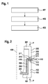
- FIG. 1 shows a flowchart of a method for manufacturing a device.
- three components are provided in a first method step 401, which are also referred to below as first, second and third component. All three components each have a plastic material. Furthermore, the components have end-side sections, hereinafter referred to as end sections, at which the components are connected to one another in the context of a laser transmission process.
- Two of the three components are (At least) formed absorbent or transparent in the region of the end portions for the laser radiation used.
- the other of the three components has at least in the region of the associated end portion in the reverse manner transparent or absorbent material properties.
- at the end portion of the second component is a transparent material
- an absorbent material is provided at the end portions of the first and third component.
- the end portions of the components or portions of the end portions may be formed of an absorbent or transparent plastic material.
- essentially the entire components may also be formed uniformly from an absorbent or transparent plastic material or may comprise such a material.
- the three components to be connected may be, for example, housing parts of the device to be manufactured.
- the device may, for example, constitute a pump device.
- the three components or housing parts to be connected to other components and elements of the device may be connected or comprise other components, which may also have other materials (for example, metallic, magnetic, ceramic materials, semiconductor materials, etc.).
- components with such materials are components of an electric motor (for example stator with coil windings and rotor with a magnetic material), electrical connection and contact elements, a control device (for example, with arranged on a printed circuit board semiconductor chips), etc.
- the three components are arranged in a further method step 402 with their respective end sections adjacent or adjacent to one another in such a way that a joining region is formed.
- the end portion of the second component is located between the end portions of the first and third components.
- connection region formed from the end sections of the three components is irradiated with a laser beam.
- the laser beam is emitted by a suitable laser welding device or laser station. With the one laser beam, two melting zones-between the end sections of the first and second and between the end sections of the second and third components-can be formed essentially simultaneously, so that after cooling or solidification of the respective melts, the three components are connected via two weld seams (FIG. Double seam ") are interconnected.
- the laser beam may be transmitted through the transparent end portion of the second member and absorbed at the absorbing end portions of the first and third members, thereby causing heating and melting of the members at these locations.
- step 403 it may further be provided to move the three components relative to the laser station or the laser beam (for example rotation about a predetermined axis of symmetry or rotation), so that two continuous welds can be produced between the three components.
- the laser station or the laser beam can also be moved along the components or along the connection region.
- the method can be carried out with only one laser welding device, whereby the method is associated with low cost and little effort.
- FIG. 1 To illustrate the method of FIG. 1 show the following Figures 2 and 3 in a schematic cross-sectional side view, the connection of three exemplary components 100, 200, 300 by means of laser transmission welding.
- the three components are also referred to below as first component 100, second component 200 and third component 300.
- first component 100, second component 200 and third component 300 It should be noted that the structures shown can only be cutouts or sections of the relevant components 100, 200, 300.
- the sections shown in cross-section can also each be substantially rotationally symmetrical to one in the Figures 2 and 3 be indicated by dashed lines rotation or longitudinal axis 430.
- the first component 100 (or its section shown in cross-section) has an L-shaped contour with a (in the Figures 2 and 3 ) horizontally extending portion 101 and a right angle (upwardly) extending portion 102.
- Each section 101, 102 of the component 100 has parallel side walls or side surfaces (for example outer and inner wall).
- the rectangular cross section in the end portion 110 has a front or front side portion 111 with a planar contour.
- the third component 300 (or its section shown in cross-section) has an L-shape comparable to the first component 100, which, however, is mirror-symmetrical to the L-shape of the first component 100.
- the third component 300 includes a (in the Figures 2 and 3 ) horizontally extending portion 301 and an orthogonal (downward) extending portion 302.
- One end of the portion 302, at which the third component 300 is connected to the second component 200, is further characterized as an end portion 310.
- Each section 301, 302 of the component 300 has parallel side walls or side surfaces (for example, outer and inner wall).
- the cross-sectionally rectangular end portion 310 has a front or front area 311 with a planar contour.
- the second component 200 (or its section shown in cross-section) has a stepped shape with a (in the Figures 2 and 3 ) horizontally extending portion 201, an orthogonal (upward) extending portion 202, and a right angle or horizontally angled end portion 210 on.
- Each section 201, 202, 210 of the second component 200 has parallel side walls or side surfaces.
- the cross-sectionally rectangular end portion 210 has a front or front-side area 211 with a planar contour.
- the front portions 111, 311 of the end portions 110, 310 abut against the sides of the end portion 210.
- the three components 100, 200, 300 in the region of the end sections 110, 210, 310 form a common connection region 410, which in FIG FIG. 2 is indicated by a dashed rectangle.
- the connection region 410 comprises four adjoining sides or surfaces of the end sections 110, 210, 310 of the components 100, 200, 300.
- the frontal region 211 of the end section 210 of the second component 200 is exposed, and can furthermore be flush with the (in FIG. 2 Right side) sides or side surfaces of the end portions 110, 310 of the components 100, 300 be.
- the second component 200 may further be formed such that in the in FIG. 2 shown connection arrangement, in which the end portion 210 is located between the end portions 110, 310, the portion 202 of the component 200 to the portion 102 of the component 100 is applied. This can be done in a corresponding manner (contrary to the illustration in FIGS Figures 2 and 3 ) may also be provided for sections 201 and 101.
- the second component 200 or at least its end portion 210 has a plastic material that is transparent to laser radiation.
- the two other components 100, 300 at least in the region of the end portions 110, 310 (or at least in the region of the front regions 111, 311) each have a plastic material with absorbent properties. In this case, both components 100, 300 may have the same or different absorbent plastic materials.
- the laser beam 440 or its laser focus is directed onto the front-side area 211 of the (transparent) end section 210 of the second component 200.
- the laser beam 440 may be coupled into the end portion 210 and transmitted to the front side portions 111, 311 of the (absorbing) end portions 110, 310 of the first and third members 100, 300 become.
- the laser radiation can be absorbed, which is associated with a temperature increase and, as a result, a melting of the materials of the first and third components 100, 300.
- thermal conduction also takes place from the end sections 110, 310 of the components 100, 300 to the end section 210 of the second component 200 arranged therebetween, which also melts in these areas.
- a material mixing can take place.
- the three components 100, 200, 300 further become, as in FIG FIG. 2 is indicated by arrows, applied with an externally applied welding / joining pressure p, whereby a sufficient heat conduction from the (absorptive) end portions 110, 310 of the components 100, 300 to the (transparent) end portion 210 of the component 200 can be caused.
- the welding / joining pressure p whose force can be effected substantially in a direction parallel to the longitudinal axis 430, can be generated, for example, by exerting a predetermined compressive force on one of the components 100, 300, whereas the other of the components 100, 300 is fixed or fixed to a corresponding holding device.
- predetermined forces can be exerted on both components 100, 300, or both components 100, 300 can be displaced by a predetermined distance.
- the laser beam 440 as in FIG. 2 be pointed in the form of an expanding beam on the joining region 410 and on the front-side portion 211 of the end portion 210.
- the radiation can be absorbed substantially over the entire thickness or cross-sectional width of the front-side regions 111, 311 of the end sections 110, 310.
- the laser beam can Or whose laser focus is selected such that an irradiation (at least) takes place over the entire thickness or cross-sectional width of the front-side region 211 of the end section 210.
- a favoring of the welding process can be brought about by a possibly relatively high intensity of the laser radiation which is suitable for melting the respective materials.
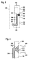
- FIG. 4 shows a section of a connection region of the components 100, 200, 300, which compared to the in FIG. 2 shown end portions 110, 210, 310 modified end portions 120, 220, 320 have.
- the angled end portion 220 of the second component 200 starting from the section 202, a straight portion 221 with parallel side walls or side surfaces, and adjacent thereto in the direction of the front-side portion 211 widening or widening section 222 with sloping side surfaces.
- the design of the end portion 220 with the widening portion 222 offers the possibility of achieving improved transmission of laser radiation to the end portions 120, 320 of the components 100, 300, and consequently to obtain greater absorption of laser radiation at these locations.
- the generation of the two melting zones in the region of the abutting end portions 120, 220 and 220, 320, and thus the formation of the two welds between the three components 100, 200, 300 may be favored.
- the size of the melting zones and, as a result the width of the weld seam can be increased. This is associated with a higher weld quality and weld strength.
- FIG. 5 shows a section of a further embodiment in which an end portion 230 of the second component 200 between end portions 130, 330 of the other components 100, 300 is arranged.
- the entire end portion 230 has a widening in the direction of the front side portion 211 form with inclined side surfaces.
- the end sections 130, 330 have contours adapted to this shape. Also in this way, the intensity of the transmission and absorption of laser radiation can be promoted, and also a large weld width of the welds formed between the end sections 130, 230 and 230, 330 can be realized.
- FIG. 6 a possible embodiment in which an end portion 240 of the second component 200 arranged between end sections 140, 340 of the first and third component 100, 300 starting from the section 202 has a straight section 241 with parallel side walls or side surfaces, and adjoining one another in FIG Direction of the frontal area 211 has widening or widening portion 242 with curved or partially circular side surfaces.
- the end sections 140, 340 in turn each have a shape adapted to the shape of the end section 240. In this way, the intensity of the transmission and absorption of laser radiation can also be promoted, and a large weld width of the welds formed between the end sections 140, 240 and 240, 340 can be achieved.
- this embodiment may also result in a corresponding design or geometry of the respective end sections in order to reliably connect the three components 100, 200, 300 with one another.
- FIG. 7 another possible embodiment, in which the second component 200 in a direction of a front side (right side in FIG. 7 ) has tapered or tapered end portion 250 with sloping surfaces.
- the other components 100, 300 have end portions 150, 350 with shapes adapted to this shape, so that the end portion 250 in the in FIG. 7 is substantially completely enclosed by the end portions 150, 350 or concealed.
- the irradiation area formed by the abutting end sections 150, 250, 350 is irradiated with a laser beam 441 from a laser welding device (not shown).
- the laser beam 441 or its laser focus is directed in particular to the end section 250 enclosed by the end sections 150, 350, so that the laser beam 441-apart from an area at the tip of the end section 250-surrounds the end section 250 (end sections 150) surrounding the end section 250 , 350 can transmit.
- the laser beam 441 may be as shown in FIG FIG. 7 indicated, unlike in the FIGS. 2 to 5
- the laser beam 440 in the form of a narrowing beam can be directed onto the connecting region of the three components 100, 200, 300 in order to make the transmission and absorption of the laser radiation more intensive.
- FIG. 8 shows a modification of the embodiment of FIG. 7 ,
- the component 200 has a tapered end portion 260, in which the inclined surfaces not as in the end portion 250 of FIG. 7 converge in a point, but adjacent to a flat front-side region 261.
- the other components 100, 300 again have the end sections 150, 350.
- the end portions 150, 350 abut against the inclined surfaces of the end portion 260, whereas the front side portion 261 is exposed.
- the region 261 may also be flush with the (in FIG. 8 Right side) sides or side surfaces of the end portions 150, 350 of the components 100, 300 be.
- FIG. 9 shows a schematic side view of an exemplary pump device in which the simultaneous welding of three plastic joining partners can be used.
- the pump device which is used for example in a cooling circuit of a motor vehicle, has a pump housing 370, an impeller receiving housing 270 and a motor housing 170.
- the housing parts 170, 270, 370 or their outer contours are essentially rotationally symmetric to a in FIG. 9 indicated longitudinal axis 430 of the pump device.
- an impeller 280 having a shaft 281 is arranged in the impeller receiving housing 270.
- the shaft 281 is rotatably supported via a holding section 271 arranged on the impeller receiving housing 270 and via a further holding section 371 provided on the pump housing 370.
- the pump housing 370 further has an inlet 372 and an outlet 373, via which a medium (for example a coolant) can be introduced into the wet space or a medium located in the wet space can leave it again.
- a medium for example a coolant
- the inlet 372 may be in the form of a suction nozzle
- the outlet 373 may be in the form of a pressure nozzle.
- the motor housing 170 comprises a bobbin 171 serving as a stator, with the aid of which the impeller 280 can be set into a rotational movement.
- the rotor 280 acting as a rotor may be formed, for example, from a plastoferror material.
- the motor housing 170 further comprises a control device 172.
- an electrical connection device 173 is also provided, via which the motor housing 170 or its components control signals and electrical current can be supplied.
- the three plastic housing parts 170, 270, 370 are connected to each other, for example via a screw connection.
- This has the disadvantage that a preload made on the screw connection due to the relaxation behavior of the plastic parts, in particular under the influence of, for example, temperature and pressure, may decrease, whereby a leakage problem may exist.
- the impeller receiving housing 270 on the end portion 220 which is formed, for example, the longitudinal axis 430 radially encircling.
- the two other housing parts 170, 370 have (the longitudinal axis 430 radially encircling) end portions with adapted to the end portion 220 forms.
- the impeller receiving housing 270 (or its end portion 220) is transparent, and the other housing parts 170, 370 (or their end portions) are formed absorbent.
- a laser beam generated by a laser station is directed to the end portion 220 to connect the housing parts 170, 270, 370 in a simultaneous manner as described above.
- the laser beam or its laser focus can be generated stationary, and the entire arrangement to the in FIG. 9 indicated longitudinal axis 430 are rotated.
- the end portions of the housing parts 170, 270, 370 may alternatively also in accordance with those in the other Figures 2 . 3 . 5, 6 . 7 be formed forms shown.
- components to be connected including those of the pump device of FIG. 9 , have different shapes and geometries.
- three joining partners to be joined (outside) may have contours which are not rotationally symmetrical to a rotational or longitudinal axis.
- the joining parts or their contours can, for example, have a rectangular shape in a plan view.
- end portions 220, 230, 240 with widening forms to realize.
- This also includes more complex shapes in which, for example, a plurality of interconnected and extending at different angles or opening angles oblique surfaces are provided.
- curved surfaces other embodiments are conceivable. These include, for example, end sections with varying curvatures or radii of curvature.
- the sub-portion 241 may be omitted, so that the end portion 240 includes only the widening portion 241.
- Modifications are in a corresponding manner for the tapered or narrowing end portions 250, 260 of the FIGS. 7 and 8 imaginable. For example, it is possible to provide curved contours instead of oblique surfaces.
Landscapes
- Engineering & Computer Science (AREA)
- Mechanical Engineering (AREA)
- Physics & Mathematics (AREA)
- Optics & Photonics (AREA)
- Health & Medical Sciences (AREA)
- Electromagnetism (AREA)
- Toxicology (AREA)
- Lining Or Joining Of Plastics Or The Like (AREA)
- Laser Beam Processing (AREA)
Applications Claiming Priority (1)
| Application Number | Priority Date | Filing Date | Title |
|---|---|---|---|
| DE201010030679 DE102010030679A1 (de) | 2010-06-29 | 2010-06-29 | Verbinden von drei Bauteilen mittels Laserdurchstrahlschweißen |
Publications (2)
| Publication Number | Publication Date |
|---|---|
| EP2402145A2 true EP2402145A2 (fr) | 2012-01-04 |
| EP2402145A3 EP2402145A3 (fr) | 2017-03-08 |
Family
ID=44760693
Family Applications (1)
| Application Number | Title | Priority Date | Filing Date |
|---|---|---|---|
| EP11167791.0A Withdrawn EP2402145A3 (fr) | 2010-06-29 | 2011-05-27 | Liaison de trois composants à l'aide de soudage par faisceau laser |
Country Status (2)
| Country | Link |
|---|---|
| EP (1) | EP2402145A3 (fr) |
| DE (1) | DE102010030679A1 (fr) |
Cited By (1)
| Publication number | Priority date | Publication date | Assignee | Title |
|---|---|---|---|---|
| EP2671705A1 (fr) * | 2012-06-07 | 2013-12-11 | Omron Corporation | Pièce en résine, capteur photoélectrique et procédé de fabrication de la pièce en résine |
Family Cites Families (3)
| Publication number | Priority date | Publication date | Assignee | Title |
|---|---|---|---|---|
| JP2001105500A (ja) * | 1999-08-05 | 2001-04-17 | Toyota Motor Corp | 樹脂成形品及びその製造方法 |
| US7522355B2 (en) * | 2004-03-31 | 2009-04-21 | Konica Minolta Opto, Inc. | Lens unit and manufacturing method thereof |
| JP4371134B2 (ja) * | 2006-09-12 | 2009-11-25 | トヨタ紡織株式会社 | フィルタ及びその製造方法 |
-
2010
- 2010-06-29 DE DE201010030679 patent/DE102010030679A1/de not_active Withdrawn
-
2011
- 2011-05-27 EP EP11167791.0A patent/EP2402145A3/fr not_active Withdrawn
Non-Patent Citations (1)
| Title |
|---|
| None |
Cited By (3)
| Publication number | Priority date | Publication date | Assignee | Title |
|---|---|---|---|---|
| EP2671705A1 (fr) * | 2012-06-07 | 2013-12-11 | Omron Corporation | Pièce en résine, capteur photoélectrique et procédé de fabrication de la pièce en résine |
| CN103481512A (zh) * | 2012-06-07 | 2014-01-01 | 欧姆龙株式会社 | 树脂部件、光电传感器以及树脂部件的制造方法 |
| CN103481512B (zh) * | 2012-06-07 | 2016-05-04 | 欧姆龙株式会社 | 光电传感器及其制造方法 |
Also Published As
| Publication number | Publication date |
|---|---|
| EP2402145A3 (fr) | 2017-03-08 |
| DE102010030679A1 (de) | 2011-12-29 |
Similar Documents
| Publication | Publication Date | Title |
|---|---|---|
| DE19641856B4 (de) | Zündkerze für einen Verbrennungsmotor | |
| DE102014100184B4 (de) | Verfahren zum Verbinden von zwei metallischen Werkstücken sowie Verfahren zum Verbinden von Kupfer und Aluminium | |
| AT525908B1 (de) | Rührschweißvorrichtung zur Herstellung einer Schweißverbindung | |
| EP4025376B1 (fr) | Dispositif de soudage et procédé de soudage d'au moins deux composants | |
| DE69323181T2 (de) | Apparat und Verfahren zur Herstellung von festen Verbindungen mittels Induktion | |
| EP3840910A1 (fr) | Procédé de soudage de pièces conductrices dans un élément constitutif d'un convertisseur électromécanique et élément constitutif d'un convertisseur électromécanique à pièces conductrices soudées | |
| EP3124162B1 (fr) | Procédé de fabrication d'un joint de soudure par recouvrement et joint de soudure par recouvrement | |
| DE102015016629A1 (de) | Herstellung eines geschweißten Strukturelements und geschweißtes Strukturelement | |
| AT519980A4 (de) | Statorkomponente für eine elektrische Maschine | |
| EP4114597A1 (fr) | Procédé de fabrication additive d'un composant tridimensionnel et système de réparation | |
| DE19512089C1 (de) | Verfahren zur Verbindung von umformbaren Blechbauteilen, vorzugsweise Feinblechen, durch Löten | |
| DE10345105A1 (de) | Konusverschluss für Laserschweissnaht an einem Bestandteil einer Luftansaugung | |
| EP2402145A2 (fr) | Liaison de trois composants à l'aide de soudage par faisceau laser | |
| DE102022211710A1 (de) | Rohlingschweissung mit vergrösserter kontaktfläche | |
| EP4147305B1 (fr) | Système de connexion et procédé de fabrication de système de connexion | |
| WO2019096740A1 (fr) | Échangeur de chaleur et son procédé de production | |
| EP1502691A1 (fr) | Assemblage brasé par recouvrement comprenant une pluralité de tôles avec un espaceur située entre une tôle supérieure et une tôle inférieure | |
| DE102019216194A1 (de) | Verfahren zum Verschweißen von Kantstäben aus einem Kupfermaterial | |
| DE112017006667B4 (de) | Verfahren zur Herstellung von Zündkerzen und Zündkerze | |
| WO2001079661A1 (fr) | Arbre a cames et procede et dispositif permettant de produire ledit arbre a cames | |
| EP3414078A1 (fr) | Procédé et dispositif pour relier des pièces profilées | |
| DE60025068T2 (de) | Schweissverfahren zum Verbinden von zweien Elementen aus Hochkohlenstoff-Stahl und Erwärmungsgerät für ein solches Verfahren | |
| WO2020187487A1 (fr) | Procédé permettant d'établir des connexions électriques entre au moins deux éléments de batterie pour une batterie d'un véhicule à moteur, en particulier une automobile | |
| DE102023004140B3 (de) | Verfahren zum Fügen von Bauteilen durch Laserschweißen sowie Laserschweißvorrichtung | |
| DE102016222088A1 (de) | Fügeverfahren zur Herstellung einer Batterie sowie Batterie |
Legal Events
| Date | Code | Title | Description |
|---|---|---|---|
| AK | Designated contracting states |
Kind code of ref document: A2 Designated state(s): AL AT BE BG CH CY CZ DE DK EE ES FI FR GB GR HR HU IE IS IT LI LT LU LV MC MK MT NL NO PL PT RO RS SE SI SK SM TR |
|
| AX | Request for extension of the european patent |
Extension state: BA ME |
|
| PUAI | Public reference made under article 153(3) epc to a published international application that has entered the european phase |
Free format text: ORIGINAL CODE: 0009012 |
|
| PUAL | Search report despatched |
Free format text: ORIGINAL CODE: 0009013 |
|
| AK | Designated contracting states |
Kind code of ref document: A3 Designated state(s): AL AT BE BG CH CY CZ DE DK EE ES FI FR GB GR HR HU IE IS IT LI LT LU LV MC MK MT NL NO PL PT RO RS SE SI SK SM TR |
|
| AX | Request for extension of the european patent |
Extension state: BA ME |
|
| RIC1 | Information provided on ipc code assigned before grant |
Ipc: B29C 65/16 20060101AFI20170201BHEP |
|
| STAA | Information on the status of an ep patent application or granted ep patent |
Free format text: STATUS: THE APPLICATION IS DEEMED TO BE WITHDRAWN |
|
| 18D | Application deemed to be withdrawn |
Effective date: 20170909 |