EP2402106A1 - Complex method of welding incombination of gas-shield ark welding with submerged ark welding - Google Patents
Complex method of welding incombination of gas-shield ark welding with submerged ark welding Download PDFInfo
- Publication number
- EP2402106A1 EP2402106A1 EP10746369A EP10746369A EP2402106A1 EP 2402106 A1 EP2402106 A1 EP 2402106A1 EP 10746369 A EP10746369 A EP 10746369A EP 10746369 A EP10746369 A EP 10746369A EP 2402106 A1 EP2402106 A1 EP 2402106A1
- Authority
- EP
- European Patent Office
- Prior art keywords
- arc welding
- gas
- matal
- welding
- electrode
- Prior art date
- Legal status (The legal status is an assumption and is not a legal conclusion. Google has not performed a legal analysis and makes no representation as to the accuracy of the status listed.)
- Granted
Links
Images

Classifications
-
- B—PERFORMING OPERATIONS; TRANSPORTING
- B23—MACHINE TOOLS; METAL-WORKING NOT OTHERWISE PROVIDED FOR
- B23K—SOLDERING OR UNSOLDERING; WELDING; CLADDING OR PLATING BY SOLDERING OR WELDING; CUTTING BY APPLYING HEAT LOCALLY, e.g. FLAME CUTTING; WORKING BY LASER BEAM
- B23K9/00—Arc welding or cutting
- B23K9/16—Arc welding or cutting making use of shielding gas
- B23K9/173—Arc welding or cutting making use of shielding gas and of a consumable electrode
- B23K9/1735—Arc welding or cutting making use of shielding gas and of a consumable electrode making use of several electrodes
-
- B—PERFORMING OPERATIONS; TRANSPORTING
- B23—MACHINE TOOLS; METAL-WORKING NOT OTHERWISE PROVIDED FOR
- B23K—SOLDERING OR UNSOLDERING; WELDING; CLADDING OR PLATING BY SOLDERING OR WELDING; CUTTING BY APPLYING HEAT LOCALLY, e.g. FLAME CUTTING; WORKING BY LASER BEAM
- B23K9/00—Arc welding or cutting
- B23K9/16—Arc welding or cutting making use of shielding gas
-
- B—PERFORMING OPERATIONS; TRANSPORTING
- B23—MACHINE TOOLS; METAL-WORKING NOT OTHERWISE PROVIDED FOR
- B23K—SOLDERING OR UNSOLDERING; WELDING; CLADDING OR PLATING BY SOLDERING OR WELDING; CUTTING BY APPLYING HEAT LOCALLY, e.g. FLAME CUTTING; WORKING BY LASER BEAM
- B23K28/00—Welding or cutting not covered by groups B23K5/00 - B23K26/00
- B23K28/02—Combined welding or cutting procedures or apparatus
-
- B—PERFORMING OPERATIONS; TRANSPORTING
- B23—MACHINE TOOLS; METAL-WORKING NOT OTHERWISE PROVIDED FOR
- B23K—SOLDERING OR UNSOLDERING; WELDING; CLADDING OR PLATING BY SOLDERING OR WELDING; CUTTING BY APPLYING HEAT LOCALLY, e.g. FLAME CUTTING; WORKING BY LASER BEAM
- B23K33/00—Specially-profiled edge portions of workpieces for making soldering or welding connections; Filling the seams formed thereby
- B23K33/004—Filling of continuous seams
-
- B—PERFORMING OPERATIONS; TRANSPORTING
- B23—MACHINE TOOLS; METAL-WORKING NOT OTHERWISE PROVIDED FOR
- B23K—SOLDERING OR UNSOLDERING; WELDING; CLADDING OR PLATING BY SOLDERING OR WELDING; CUTTING BY APPLYING HEAT LOCALLY, e.g. FLAME CUTTING; WORKING BY LASER BEAM
- B23K9/00—Arc welding or cutting
- B23K9/02—Seam welding; Backing means; Inserts
- B23K9/025—Seam welding; Backing means; Inserts for rectilinear seams
-
- B—PERFORMING OPERATIONS; TRANSPORTING
- B23—MACHINE TOOLS; METAL-WORKING NOT OTHERWISE PROVIDED FOR
- B23K—SOLDERING OR UNSOLDERING; WELDING; CLADDING OR PLATING BY SOLDERING OR WELDING; CUTTING BY APPLYING HEAT LOCALLY, e.g. FLAME CUTTING; WORKING BY LASER BEAM
- B23K9/00—Arc welding or cutting
- B23K9/09—Arrangements or circuits for arc welding with pulsed current or voltage
-
- B—PERFORMING OPERATIONS; TRANSPORTING
- B23—MACHINE TOOLS; METAL-WORKING NOT OTHERWISE PROVIDED FOR
- B23K—SOLDERING OR UNSOLDERING; WELDING; CLADDING OR PLATING BY SOLDERING OR WELDING; CUTTING BY APPLYING HEAT LOCALLY, e.g. FLAME CUTTING; WORKING BY LASER BEAM
- B23K9/00—Arc welding or cutting
- B23K9/16—Arc welding or cutting making use of shielding gas
- B23K9/173—Arc welding or cutting making use of shielding gas and of a consumable electrode
-
- B—PERFORMING OPERATIONS; TRANSPORTING
- B23—MACHINE TOOLS; METAL-WORKING NOT OTHERWISE PROVIDED FOR
- B23K—SOLDERING OR UNSOLDERING; WELDING; CLADDING OR PLATING BY SOLDERING OR WELDING; CUTTING BY APPLYING HEAT LOCALLY, e.g. FLAME CUTTING; WORKING BY LASER BEAM
- B23K9/00—Arc welding or cutting
- B23K9/18—Submerged-arc welding
-
- B—PERFORMING OPERATIONS; TRANSPORTING
- B23—MACHINE TOOLS; METAL-WORKING NOT OTHERWISE PROVIDED FOR
- B23K—SOLDERING OR UNSOLDERING; WELDING; CLADDING OR PLATING BY SOLDERING OR WELDING; CUTTING BY APPLYING HEAT LOCALLY, e.g. FLAME CUTTING; WORKING BY LASER BEAM
- B23K9/00—Arc welding or cutting
- B23K9/18—Submerged-arc welding
- B23K9/186—Submerged-arc welding making use of a consumable electrodes
- B23K9/188—Submerged-arc welding making use of a consumable electrodes making use of several electrodes
-
- B—PERFORMING OPERATIONS; TRANSPORTING
- B23—MACHINE TOOLS; METAL-WORKING NOT OTHERWISE PROVIDED FOR
- B23K—SOLDERING OR UNSOLDERING; WELDING; CLADDING OR PLATING BY SOLDERING OR WELDING; CUTTING BY APPLYING HEAT LOCALLY, e.g. FLAME CUTTING; WORKING BY LASER BEAM
- B23K2101/00—Articles made by soldering, welding or cutting
- B23K2101/18—Sheet panels
-
- B—PERFORMING OPERATIONS; TRANSPORTING
- B23—MACHINE TOOLS; METAL-WORKING NOT OTHERWISE PROVIDED FOR
- B23K—SOLDERING OR UNSOLDERING; WELDING; CLADDING OR PLATING BY SOLDERING OR WELDING; CUTTING BY APPLYING HEAT LOCALLY, e.g. FLAME CUTTING; WORKING BY LASER BEAM
- B23K2103/00—Materials to be soldered, welded or cut
- B23K2103/02—Iron or ferrous alloys
- B23K2103/04—Steel or steel alloys
Definitions
- the present invention relates to a hybrid or combination welding method of performing welding on a steel plate by the combination of gas-metal arc welding (or gas shield arc welding or gas-shieled metal arc welding) and submerged-arc welding and a hybrid or combination arc welding machine thereof.
- submerged-arc welding is a welding technique with excellent construction efficiency since high-heat input welding may be performed which conducts welding in one pass by setting a large welding current. Furthermore, since melted metal is protected by slag, there are advantages in that nitrogen or oxygen is suppressed from being mixed into the melted metal and a stable arc is obtained. For this reason, since a weld defect is suppressed and weld metal with an excellent mechanical property is obtained, the submerged-arc welding is widely used in various fields (for example, shipbuilding, architecture, civil engineering, and the like).
- PTLs 1 to 7 disclose a technique that simultaneously prevents the deterioration of the toughness of the HAZ and improves the efficiency of the weld construction by performing gas matal arc welding and submerged-arc welding on the same weld line.
- an inert gas mainly containing Ar is used as a shielding gas of the gas matal arc welding (MIG welding (metal inert gas welding)
- MIG welding metal inert gas welding
- the penetration is not deep, so that the fractionation effect of the heat input in the thickness direction of the steel plate may not be sufficiently obtained and the improvement of the toughness of the HAZ may not be attained.
- the inventors have reviewed a technique for preventing a deterioration of toughness of a HAZ in hybrid and combination welding using the combination of gas matal arc welding and submerged-arc welding.
- (a) When the arc pressure becomes stronger by increasing the current density of a first electrode 12 of gas matal arc welding to have a large depth of penetration, the heat of the gas matal arc welding is deeply input in the thickness direction of a steel plate, and the heat of submerged-arc welding is input to the surface layer side thereof to be fractionated, so that a deterioration of toughness of a HAZ 30 is prevented.
- gas matal arc welding metal has a shape in which a bead extends in the thickness direction of the steel plate, and the possibility of generating a hot crack drastically increases. Therefore, (b) When the center-to-center spacing (hereinafter, referred to as a distance between electrodes) between the last electrode of the gas matal arc welding and the first electrode of the submerged-arc welding at the surface of the steel plate is narrowed, the solidification direction of the weld metal formed by the gas shield arc is controlled to be upward, and the hot crack is suppressed.
- a distance between electrodes hereinafter, referred to as a distance between electrodes
- the invention is a combination welding method and a combination arc welding machine thereof, where gas matal arc welding is performed on a butted portion between steel plates.
- the combination welding method submerged-arc welding is performed behind the gas matal arc welding, the gas matal arc welding is performed by using two or more electrodes, a wire for welding having a wire diameter of 1.4 mm or more is used in a first electrode 12 of the gas matal arc welding, and the current density of the first electrode 12 of the gas matal arc welding is set to 320 A/mm 2 or more.
- a gas matal arc welding machine using two or more electrodes is disposed at the front position to perform the welding, and a submerged-arc welding machine using multielectrodes is disposed at the rear position.
- a distance between the last electrode of the gas matal arc welding and the first electrode 16 of the submerged-arc welding is preferably from 40 to 100 mm.
- the submerged-arc welding may be performed using two or more electrodes, and the current density of the first electrode 16 of the submerged-arc welding is preferably 75 A/mm 2 or more.
- a distance between the first and second electrodes 12 and 13 of the gas matal arc welding is preferably 30 mm or less.
- the first and second electrodes 12 and 13 of the gas matal arc welding are preferably set to have different polarities.
- power supplies of the first and second electrodes 12 and 13 of the gas matal arc welding are preferably pulsed power supplies respectively, and peak currents of the first and second electrodes 12 and 13 of the gas matal arc welding may be supplied to be deviated from each other in time.
- the current ratio between the first and second electrodes 16 and 17 of the submerged-arc welding is preferably from 0.6 to 0.8.
- the deterioration of the toughness of the HAZ 30 may be prevented and construction may be highly efficiently performed. Furthermore, a satisfactory weld metal without a weld defect is obtained.
- welding is performed in one pass by the combination of gas matal arc welding and submerged-arc welding in order to fractionate a heat input in the thickness direction of a steel plate.
- the succeeding gas matal arc welding is performed while flux and slag remain on the surface of melted metal, which inhibits the generation of arc in the gas matal arc welding.
- the gas matal arc welding not using flux and not generating slag is performed before the submerged-arc welding, and the submerged-arc welding is performed before the melted metal of the gas matal arc welding is solidified.
- gas matal arc welding using multielectrodes (in Figs. 3 and 4 : 12, 13, 14, and 15) equal to or more than two electrodes (that is, wires for welding) and submerged-arc welding using multielectrodes (in Figs. 3 and 4 : 16, 17, 18, and 19) are performed. Since the gas matal arc welding and the submerged-arc welding both use multielectrodes, the rate of deposition increases, so that the weld efficiency improves.
- a molten pool 23 is formed in an elongated shape in the weld direction, it is possible to ensure a time necessary for causing rising of a gas 24 or molten slag, and hence suppress blowholes or entrapment of slag from being generated in weld metals 21 and 22. As a result, it is possible to prevent a weld defect from being generated in the weld metals 21 and 22 formed by solidifying the melted metal 23. Further, when the heat input in the thickness direction of the steel plate is fractionated, effects for suppressing grain coarsening of a structure of a HAZ 30 and preventing a deterioration of toughness of the HAZ 30 are obtained.
- the electrodes (12, 13, 14, and 15) of the gas matal arc welding and the electrodes (16, 17, 18, and 19) of the submerged-arc welding be all disposed on the same weld line.
- the reason is as follows. When the electrode is deviated from the weld line, the heat input amount at the weld line is not sufficient, so that the flow of the molten metal inside the molten pool 23 to rear welding is disturbed, which causes various weld defects and a deterioration of a bead shape.
- the invention will be described in detail.
- the wire diameter of the wire for welding used as a first electrode 12 of the gas matal arc welding using multielectrodes and the current density of the first electrode 12 of the gas matal arc welding are defined.
- the first electrode 12 of the gas matal arc welding indicates the electrode disposed at the foremost position of a plurality of electrodes of the gas matal arc welding in the proceeding direction.
- the wire diameter of the wire 33 for welding used in the first electrode 12 of the gas matal arc welding is less than 1.4 mm, the current density may be increased, but the welding current is not easily increased and the arc pressure is deteriorated, so that a sufficient depth of penetration is not obtained. Accordingly, the wire diameter of the wire is set to 1.4 mm or more. On the other hand, if a high current is applied when the wire diameter becomes more than 2.4 mm, an excessive heat amount is input, so that the toughness of the HAZ 30 is deteriorated. Also, since the current density reduces at a low current, sufficient penetration is not obtained. Accordingly, it is desirable that the wire diameter of the wire 33 used in the first electrode 12 of the gas matal arc welding be in the range from 1.4 to 2.4 mm.
- the current density of the welding current supplied to the first electrode 12 of the gas matal arc welding is less than 320 A/mm 2 , the arc pressure reduces, so that the sufficient depth of penetration is not obtained. Accordingly, the current density is set to be 320 A/mm 2 or more.
- the current density becomes excessively large, the arc pressure becomes strong, so that the depth of penetration becomes larger.
- the melted metal 23 which is elongated in the thickness direction of the steel plate 1 is formed, and the solidification speed of the front end of the melted metal 23 becomes faster. For this reason, the gas 24 included in the melted metal 23 is captured, so that blowholes are easily generated in the weld metal 21.
- the gas matal arc welding using multielectrodes since the gas matal arc welding using multielectrodes is adopted, it is possible to adjust the solidification speed of the melted metal 23 or the flow of melted metal thereof by using the input heat after the second electrode 13 of the succeeding gas matal arc welding, and it is possible to suppress the generation of the blowholes.
- the current density of the welding current supplied to the first electrode 12 of the gas matal arc welding becomes more than 700 Almm 2 , the arc pressure is too strong. Therefore, even in the gas matal arc welding using multielectrodes, the movement of the molten pool 23 becomes much too fierce, so that a fusion defect or blowholes are generated or a bead is irregular.
- the current density of the welding current supplied to the first electrode 12 of the gas matal arc welding be in the range from 320 to 700 A/mm 2 .
- the current density indicates the welding current per the unit area of the cross-section of the wire for welding.
- the gas matal arc welding used in the invention is not particularly limited.
- carbon gas welding is desirable in which CO 2 gas having a strong arc pressure and obtaining deep penetration is used as a shielding gas.
- the CO 2 gas may be mixed with Ar gas whose content may be up to 60 vol%. Accordingly, the composition of the shielding gas is desirable when the CO 2 gas is 100 to 40 vol% and the Ar gas as a remainder is 0 to 60 vol%.
- the wire 33 for welding of the gas matal arc welding is not particularly limited.
- a solid wire or a flux cored wire may be used.
- the number of weld electrodes may be appropriately selected in accordance with the thickness of the steel plate or the shape of the groove, and two or more electrodes are desirable from the viewpoint of the productivity or quality of the welding.
- the number of electrodes is not limited. However, when the number of electrodes increases, a gas matal arc welding machine becomes more expensive and the configuration of the welding machine becomes more complex. For this reason, four or less electrodes are desirable.
- a first electrode 16 of the submerged-arc welding indicates the electrode disposed at the foremost position of the plurality of electrodes of the submerged-arc welding in the proceeding direction.
- the distance between the first electrode 12 of the gas matal arc welding and the second electrode 13 of the gas matal arc welding becomes more than 30 mm, the weld metal formed by the first electrode 12 is not melted by the second electrode 13. Therefore, when a weld defect is contained in the weld metal 21 formed by the first electrode 12, the weld defect remains in the weld metal 21. Accordingly, it is desirable that the distance between the first electrode 12 of the gas matal arc welding and the second electrode 13 of the gas matal arc welding be 30 mm or less. On the other hand, when the distance is less than 8 mm, the arc is disturbed by magnetic blow, which causes various weld defects. Accordingly, it is more desirable that the distance between the first electrode 12 of the gas matal arc welding and the second electrode 13 of the gas matal arc welding be in the range from 8 to 30 mm.
- the arcs 25 attract each other, so that the melted metal 23 rises to thereby easily form a pouring basin. Since the first electrode 12 of the gas matal arc welding irregularly comes into contact with the second electrode 13 of the gas matal arc welding due to the fluctuation of the pouring basin, the arc 25 becomes unstable.
- the polarity of the first electrode 12 of the gas matal arc welding is set to be opposite to the polarity of the second electrode 13 of the gas matal arc welding, the arcs 25 repel each other, so that the melted metal 23 is press-inserted to thereby hardly form the pouring basin. Therefore, it is desirable that the polarity of the first electrode 12 of the gas matal arc welding be different from the polarity of the second electrode 13 of the gas matal arc welding.
- the first electrode 12 of the gas matal arc welding has reversed polarity (that is, the electrode is set as a positive electrode) and the second electrode 13 of the gas matal arc welding has straight polarity (that is, the electrode is set as a negative electrode), it is more desirable that the depth of penetration becomes larger.
- the polarity of the first electrode 12 of the gas matal arc welding is the same as the polarity of the second electrode 13 of the gas matal arc welding, it is desirable that pulsed power supplies be used in the first electrode 12 of the gas matal arc welding and the second electrode 13 of the gas matal arc welding and the peak currents (that is, welding currents) thereof be deviated from each other in time. The reason is because the phenomenon that the arcs 25 attract each other may be suppressed.
- the welding speed is set to be equal to that of the gas matal arc welding. Then, in the submerged-arc welding, it is desirable that the penetration be performed up to the position where the hot crack is easily generated in the gas matal arc welding portion. Accordingly, it is desirable that the gas matal arc welding machine and the submerged-arc welding machine be disposed as shown in Fig. 5 and a work 37 be welded while being loaded and moved on a carriage 38. Alternatively, when the work is not moved, it is desirable that the gas matal arc welding machine and the submerged-arc welding machine be loaded on one carriage 37 and welding be performed while moving the combination arc welding machine (not shown).
- the current density of the welding current supplied to the first electrode 16 of the submerged-arc welding using the multielectrodes is less than 75 A/mm 2 , the arc pressure is weak and the deep depth of penetration is not obtained. Therefore, it is not possible to sufficiently obtain an effect that prevents the hot crack of the weld metal 21 of the gas matal arc welding or prevents the hot crack by melting the hot crack again. Accordingly, it is desirable that the current density be 75 A/mm 2 or more. When the current density becomes excessively larger, the penetration becomes too deep and the heat is input up to the lower side, so that the heat fractionation effect is not obtained.
- the arc pressure is high, the melted metal 23 behind the arc 25 flows fiercely backward, and the molten pool 23 is vibrated, so that slag or a residual material of a surface of a groove is entangled. Therefore, the flux or slag is included in the melted metal 23 to thereby easily generate a weld defect in the weld metal 22.
- the submerged-arc welding using the multielectrodes is adopted, it is possible to adjust the solidification speed of the melted metal 23 using the input heat after a second electrode 17 of the succeeding submerged-arc welding and thus suppress the generation of the weld defect.
- the current density of the welding current supplied to the first electrode 16 of the submerged-arc welding becomes more than 350 A/mm 2 , the heat fractionation effect reduces and the toughness of the HAZ 30 is deteriorated. Accordingly, it is desirable that the current density of the welding current supplied to the first electrode 16 of the submerged-arc welding be in the range from 75 to 350 A/mm 2 . Furthermore, the first electrode 16 of the submerged-arc welding indicates the electrode disposed at the foremost position of the plurality of electrodes of the submerged-arc welding in the proceeding direction.
- a current ratio calculated from the welding current I 1 (A) supplied to the first electrode 16 of the submerged-arc welding and the welding current I 2 (A) supplied to the second electrode 17 of the submerged-arc welding is less than 0. 6
- a weld defect such as slag inclusion is easily generated.
- the current ratio becomes more than 0.8, a weld defect such as an undercut is easily generated. Accordingly, it is desirable that the current ratio be in the range from 0.6 to 0.8.
- the submerged-arc welding used in the invention is not particularly limited.
- the flux 36 fused flux, bonded flux, or the like may be used.
- basic flux containing a large amount of CaO or CaF 2 is desirable as the flux 36.
- the wire 34 for welding is not particularly limited.
- a solid wire or a flux cored wire may be used.
- the number of weld electrodes may be appropriately selected in accordance with the thickness of the steel plate or the shape of the groove, and two or more electrodes are desirable from the viewpoint of the productivity or quality of the welding.
- the number of electrodes of the submerged-arc welding is not limited. However, when the number of electrodes increases, a submerged-arc welding machine becomes more expensive and the configuration of the welding machine becomes more complex. For this reason, four or less electrodes are desirable.
- the deterioration of the toughness of the HAZ 30 is prevented by fractionating the heat input in the thickness direction of the steel plate by using both the gas matal arc welding and the submerged-arc welding. Furthermore, since the welding may be performed in one pass, the welding technique has excellent construction efficiency. Furthermore, the invention also has an effect of suppressing the generation of a weld defect. Accordingly, a satisfactory weld joint is obtained.
- the steel plates having the components shown in Table 1 were welded while abutting on each other.
- the groove shape is as shown in Fig. 1 ; the groove angles 5 and 6, the groove depths 7 and 8, the groove areas 9 and 10, and the length of the root face 11 are shown in Table 4.
- the thickness 4 of the steel plate 1 was set to 25 mm, 33 mm, and 38 mm. In three types of steel plates 1 having different thicknesses 4, the yield strength was from 620 to 650 MPa, and the tensile strength was from 710 to 740 MPa.
- the invention was not applied, but submerged-arc welding using three electrodes was performed.
- the welding conditions are shown in Table 2.
- the wire for welding the wire for welding having a wire diameter of 4.0 mm was used among the wires for welding shown in Table 3.
- the flux basic fused flux mainly containing CaO-CaF 2 -SiO 2 -Al 2 O 3 was used.
- the invention was applied, and welding was performed in one pass by using both gas matal arc welding and submerged-arc welding.
- the welding conditions of the preceding gas matal arc welding are shown in Table 5, and the welding conditions of the succeeding submerged-arc welding are shown in Table 6.
- 100 vol% of CO 2 was used as a shielding gas at the flow rate of 25 liters/minute, the first electrode 12 of the gas matal arc welding was made to have reversed polarity, and the second electrode 13 of the gas matal arc welding was made to have straight polarity.
- a V-notch Charpy impact test piece 28 of JIS Z2202 (1980) was collected from the HAZ 30 of the finishing side 3 and was subjected to a Charpy impact test at -40°C.
- the result is also shown in Table 6.
- Fig. 2 illustrates the collection position (2 mm away from the surface of the steel plate in the thickness direction) of the Charpy impact test piece 28.
- the notch 29 was set to a position where the base material (including the HAZ) and the weld metal were present in the ratio of one to one.
- the distance between the electrodes of Table 5 indicates a gap between the first electrode 12 of the preceding gas matal arc welding and the second electrode 13 of the gas matal arc welding, a gap between the second electrode 13 of the gas matal arc welding and a third electrode 14 of the gas matal arc welding, and a gap between the third electrode 14 of the gas matal arc welding and a fourth electrode 15 of the gas matal arc welding.
- the distance between electrodes of Table 6 indicates a gap between the last electrode of the preceding gas matal arc welding and the first electrode 16 of the succeeding submerged-arc welding.
- the thickness 4 of the steel plate of Table 5 corresponds to Table 4, and the dimension of each groove is shown in Table 4.
- the wire diameter of Tables 5 and 6 corresponds to that of Table 3, and the component of each wire for welding is shown in Table 3.
- the inventive example is an example in which the wire diameter of the wire 33 for welding used in the first electrode 12 of the gas matal arc welding and the current density of the first electrode 12 of the gas matal arc welding satisfy the range of the invention.
- Inventive Example that is, the welding Nos. 1 to 3 has an extremely satisfactory toughness when the strength or the component of the steel plate 1 is taken into consideration.
- the first electrode 12 of the gas matal arc welding and the second electrode 13 of the gas matal arc welding were made to have reversed polarities, and welding was performed on the steel plate 1 with the same conditions as that of the welding No. 1.
- the arc 25 in the gas matal arc welding became unstable. For this reason, even when no problem occurred in the submerged-arc welding, blowholes were found in the weld metal 21.
- the first electrode 12 of the gas matal arc welding and the second electrode 13 of the gas matal arc welding were made to have reversed polarities, pulsed power supplies were used so that the peak currents of the first electrode 12 of the gas matal arc welding and the second electrode 13 of the gas matal arc welding were deviated from each other in time, and welding was performed on the steel plate 1 with the same conditions as that of the welding No. 1.
- the arc 25 in the gas matal arc welding was stable, and no blowhole was generated in the weld metal 21.
- the steel plates having the components shown in Table 1 were welded while abutting on each other.
- the groove shape was as shown in Fig. 1 ; the groove angles 5 and 6, the groove depths 7 and 8, the groove areas 9 and 10, and the length of the root face 11 are shown in Table 4.
- the thickness 4 of the steel plate 1 was set to 25 mm, 33 mm, and 38 mm. In three types of steel plates 1 having different thicknesses 4, the yield strength was from 620 to 650 MPa, and the tensile strength was from 710 to 740 MPa.
- the invention was not applied, but submerged-arc welding using three electrodes was performed.
- the welding conditions are shown in Table 2.
- the wire for welding the wire for welding having a wire diameter of 4.0 mm was used among the wires for welding shown in Table 3.
- the flux basic fused flux mainly containing CaO-CaF 2 -SiO 2 -Al 2 O 3 was used.
- the invention was applied, and welding was performed in one pass by using both gas matal arc welding and submerged-arc welding.
- the welding conditions of the preceding gas matal arc welding are shown in Table 7, and the welding conditions of the succeeding submerged-arc welding are shown in Table 8.
- 100 vol% of CO 2 was used as a shielding gas at the flow rate of 25 liter/minute
- the first electrode 12 of the gas matal arc welding was made to have reversed polarity
- the second electrode 13 of the gas matal arc welding was made to have straight polarity.
- the test piece 28 was collected from the HAZ 30 of the finishing side 3, and was subjected to a Charpy impact test at -40°C. The result is also shown in Table 8.
- the distance between the electrodes of Table 7 indicates a gap between the first electrode 12 of the preceding gas matal arc welding and the second electrode 13 of the gas matal arc welding, a gap between the second electrode 13 of the gas matal arc welding and the third electrode 14 of the gas matal arc welding, and a gap between the third electrode 14 of the gas matal arc welding and the fourth electrode 15 of the gas matal arc welding.
- the distance between the electrodes of Table 8 indicates a gap between the last electrode of the preceding gas matal arc welding and the first electrode of the succeeding submerged-arc welding.
- the thickness 4 of the steel plate of Table 7 corresponds to Table 4, and the dimension of each groove is shown in Table 4.
- the wire diameter of Tables 7 and 8 corresponds to that of Table 3, and the component of each wire for welding is shown in Table 3.
- the inventive example is an example in which the wire diameter of the wire 33 for welding used in the first electrode 12 of the gas matal arc welding and the current density of the first electrode 12 of the gas matal arc welding satisfy the range of the invention.
- Inventive Example that is, the welding Nos. 8 to 10, 13, and 14
- the current density of the first electrode 12 of the gas matal arc welding was sufficient, but the depth of penetration was reduced due to a decrease in welding current.
- the first electrode 12 of the gas matal arc welding and the second electrode 13 of the gas matal arc welding were made to have reversed polarities, pulsed power supplies were used so that the peak currents of the first electrode 12 of the gas matal arc welding and the second electrode 13 of the gas matal arc welding were deviated from each other in time, and welding was performed on the steel plate 1 with the same conditions as that of the welding No. 1.
- the arc 25 in the gas matal arc welding was stable, and no blowhole was generated in the weld metal 21.
Landscapes
- Engineering & Computer Science (AREA)
- Mechanical Engineering (AREA)
- Physics & Mathematics (AREA)
- Plasma & Fusion (AREA)
- Arc Welding In General (AREA)
Abstract
Description
- The present invention relates to a hybrid or combination welding method of performing welding on a steel plate by the combination of gas-metal arc welding (or gas shield arc welding or gas-shieled metal arc welding) and submerged-arc welding and a hybrid or combination arc welding machine thereof.
- Generally, submerged-arc welding is a welding technique with excellent construction efficiency since high-heat input welding may be performed which conducts welding in one pass by setting a large welding current. Furthermore, since melted metal is protected by slag, there are advantages in that nitrogen or oxygen is suppressed from being mixed into the melted metal and a stable arc is obtained. For this reason, since a weld defect is suppressed and weld metal with an excellent mechanical property is obtained, the submerged-arc welding is widely used in various fields (for example, shipbuilding, architecture, civil engineering, and the like).
- In recent years, there has been a tendency that the thickness of the steel plate subjected to the submerged-arc welding has increased with an increase in size of a welded structure, so that there are demands for a new high-heat input welding technique.
Incidentally, when the heat input amount increases during welding, the toughness of a welded heat affected zone (hereinafter, referred to as HAZ) is deteriorated, so that a sufficient performance is not obtained at a weld joint. Although a method may be supposed which prevents the deterioration of the toughness of the HAZ by performing multilayer welding and fractionating a heat input amount, the efficiency of the submerged-arc welding is drastically deteriorated. Therefore, a technique has been considered which uses both submerged-arc welding and gas matal arc welding to prevent the deterioration of the toughness of the HAZ and improve the efficiency of the weld construction. - For example,
PTLs 1 to 7 disclose a technique that simultaneously prevents the deterioration of the toughness of the HAZ and improves the efficiency of the weld construction by performing gas matal arc welding and submerged-arc welding on the same weld line. However, in such a technique, since an inert gas mainly containing Ar is used as a shielding gas of the gas matal arc welding (MIG welding (metal inert gas welding)), a penetrative energy caused by an arc pressure is weak and penetration is not deep. Alternatively, since the current density of the gas matal arc welding is small, the penetration is not deep, so that the fractionation effect of the heat input in the thickness direction of the steel plate may not be sufficiently obtained and the improvement of the toughness of the HAZ may not be attained. - Further, in
PTL 5, since a wire with a large diameter of 3 to 6.4 mm is adopted as the electrode of the gas matal arc welding, the current density is low, so that there are problems in that the arc pressure reduces and the depth of penetration decreases.
Further, inPTL 6, since the electrode of the gas matal arc welding is vibrated in the direction perpendicular to the weld proceeding direction, there are problems in that the arc pressure reduces and the depth of penetration decreases. -
- [PTL 1]
JP-A-S58-32583 - [PTL 2]
JP-A-H3-81070 - [PTL 3]
JP-A-S60-15067 - [PTL 4]
JP-A-S59-30481 - [PTL 5]
JP-A-S54-10263 - [PTL 6]
JP-A-S53-13024 - [PTL 7]
JP-A-S53-119240 - It is an object of the invention to provide a hybrid or combination welding method and a welding machine thereof having excellent construction efficiency and preventing a deterioration of toughness of a
HAZ 30 by deepening the penetration of gas matal arc welding to deeply input the heat of the gas matal arc welding into a steel plate in the thickness direction and inputting the heat of submerged-arc welding to the surface layer side thereof to be fractionated so that the structure of a HAZ 30 (a welded heat affected zone) becomes smaller at the time of welding the steel plate by the combination of the gas matal arc welding using multielectrodes and the submerged-arc welding using multielectrodes. - The inventors have reviewed a technique for preventing a deterioration of toughness of a HAZ in hybrid and combination welding using the combination of gas matal arc welding and submerged-arc welding.
As a result, (a) When the arc pressure becomes stronger by increasing the current density of afirst electrode 12 of gas matal arc welding to have a large depth of penetration, the heat of the gas matal arc welding is deeply input in the thickness direction of a steel plate, and the heat of submerged-arc welding is input to the surface layer side thereof to be fractionated, so that a deterioration of toughness of aHAZ 30 is prevented.
However, when the depth of penetration of the gas matal arc welding is deepened in this manner, gas matal arc welding metal has a shape in which a bead extends in the thickness direction of the steel plate, and the possibility of generating a hot crack drastically increases.
Therefore, (b) When the center-to-center spacing (hereinafter, referred to as a distance between electrodes) between the last electrode of the gas matal arc welding and the first electrode of the submerged-arc welding at the surface of the steel plate is narrowed, the solidification direction of the weld metal formed by the gas shield arc is controlled to be upward, and the hot crack is suppressed.
(c) Alternatively, when the arc pressure becomes stronger by increasing the current density of afirst electrode 16 of the submerged-arc welding to have a large depth of penetration, the hot crack generated at the upside of the weld metal of the gas matal arc welding is melted again, so that a high-quality weld portion without a hot crack is obtained.
(d) Further, in the gas matal arc welding metal having a feature that the penetration is deep and the shape is thin and elongated, the solidification speed is fast and blowholes are easily generated. However, when multielectrodes are used, a time necessary for the rising of agas 24 is ensured by makingmolten pool 23 have an elongated shape in the weld direction, so that a weld defect such as a blowhole is suppressed. - The invention is based on this knowledge.
That is, the invention is a combination welding method and a combination arc welding machine thereof, where gas matal arc welding is performed on a butted portion between steel plates. In the combination welding method, submerged-arc welding is performed behind the gas matal arc welding, the gas matal arc welding is performed by using two or more electrodes, a wire for welding having a wire diameter of 1.4 mm or more is used in afirst electrode 12 of the gas matal arc welding, and the current density of thefirst electrode 12 of the gas matal arc welding is set to 320 A/mm2 or more. In the combination arc welding machine, a gas matal arc welding machine using two or more electrodes is disposed at the front position to perform the welding, and a submerged-arc welding machine using multielectrodes is disposed at the rear position. - In the combination welding method and the combination arc welding machine according to the invention, a distance between the last electrode of the gas matal arc welding and the
first electrode 16 of the submerged-arc welding is preferably from 40 to 100 mm.
Further, in the combination welding method and the combination arc welding machine according to the invention, the submerged-arc welding may be performed using two or more electrodes, and the current density of thefirst electrode 16 of the submerged-arc welding is preferably 75 A/mm2 or more.
Further, in the combination welding method and the combination arc welding machine according to the invention, a distance between the first andsecond electrodes
Further, in the combination welding method and the combination arc welding machine according to the invention, the first andsecond electrodes
Further, in the combination welding method and the combination arc welding machine according to the invention, power supplies of the first andsecond electrodes second electrodes
Furthermore, in the combination welding method and the combination arc welding machine according to the invention, the current ratio between the first andsecond electrodes - According to the invention, since gas matal arc welding using multielectrodes and submerged-arc welding using multielectrodes are both used and the current density of the
first electrode 12 of the gas matal arc welding and the current density of thefirst electrode 16 of the submerged-arc welding are all increased at the time of welding the steel plate, the deterioration of the toughness of the HAZ 30 may be prevented and construction may be highly efficiently performed. Furthermore, a satisfactory weld metal without a weld defect is obtained. -
-
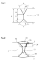
Fig. 1 is a cross-sectional view schematically illustrating a shape of a groove adopting a combination welding method of the invention. -
Fig. 2 is a cross-sectional view illustrating a weld portion subjected to a combination welding method of the invention and a diagram illustrating a position of collecting a Charpy impact test piece. -
Fig. 3 is a cross-sectional view illustrating amolten pool 23 during welding of the combination welding method of the invention. -
Fig. 4 is a plan view illustrating themolten pool 23 during welding of the combination welding method of the invention. -
Fig. 5 is a diagram illustrating an example of a combination arc welding machine of the invention. Description of Embodiments - In the invention, welding is performed in one pass by the combination of gas matal arc welding and submerged-arc welding in order to fractionate a heat input in the thickness direction of a steel plate. However, when the submerged-arc welding is performed before the gas matal arc welding, the succeeding gas matal arc welding is performed while flux and slag remain on the surface of melted metal, which inhibits the generation of arc in the gas matal arc welding. For this reason, as shown in
Figs. 3 and 4 , the gas matal arc welding not using flux and not generating slag is performed before the submerged-arc welding, and the submerged-arc welding is performed before the melted metal of the gas matal arc welding is solidified. - In the gas matal arc welding and the submerged-arc welding, gas matal arc welding using multielectrodes (in
Figs. 3 and 4 : 12, 13, 14, and 15) equal to or more than two electrodes (that is, wires for welding) and submerged-arc welding using multielectrodes (inFigs. 3 and 4 : 16, 17, 18, and 19) are performed. Since the gas matal arc welding and the submerged-arc welding both use multielectrodes, the rate of deposition increases, so that the weld efficiency improves. In addition, since amolten pool 23 is formed in an elongated shape in the weld direction, it is possible to ensure a time necessary for causing rising of agas 24 or molten slag, and hence suppress blowholes or entrapment of slag from being generated inweld metals weld metals metal 23. Further, when the heat input in the thickness direction of the steel plate is fractionated, effects for suppressing grain coarsening of a structure of aHAZ 30 and preventing a deterioration of toughness of theHAZ 30 are obtained. - As shown in
Fig. 4 , it is desirable that the electrodes (12, 13, 14, and 15) of the gas matal arc welding and the electrodes (16, 17, 18, and 19) of the submerged-arc welding be all disposed on the same weld line. The reason is as follows. When the electrode is deviated from the weld line, the heat input amount at the weld line is not sufficient, so that the flow of the molten metal inside themolten pool 23 to rear welding is disturbed, which causes various weld defects and a deterioration of a bead shape. - Hereinafter, the invention will be described in detail.
In the preceding gas matal arc welding, since there is a need to fractionate the heat input in the thickness direction of the steel plate in order to prevent the deterioration of the toughness of theHAZ 30, the depth of penetration is set to be large. Therefore, the wire diameter of the wire for welding used as afirst electrode 12 of the gas matal arc welding using multielectrodes and the current density of thefirst electrode 12 of the gas matal arc welding are defined. Furthermore, thefirst electrode 12 of the gas matal arc welding indicates the electrode disposed at the foremost position of a plurality of electrodes of the gas matal arc welding in the proceeding direction. - When the wire diameter of the
wire 33 for welding used in thefirst electrode 12 of the gas matal arc welding is less than 1.4 mm, the current density may be increased, but the welding current is not easily increased and the arc pressure is deteriorated, so that a sufficient depth of penetration is not obtained. Accordingly, the wire diameter of the wire is set to 1.4 mm or more. On the other hand, if a high current is applied when the wire diameter becomes more than 2.4 mm, an excessive heat amount is input, so that the toughness of theHAZ 30 is deteriorated. Also, since the current density reduces at a low current, sufficient penetration is not obtained. Accordingly, it is desirable that the wire diameter of thewire 33 used in thefirst electrode 12 of the gas matal arc welding be in the range from 1.4 to 2.4 mm. - Further, when the current density of the welding current supplied to the
first electrode 12 of the gas matal arc welding is less than 320 A/mm2, the arc pressure reduces, so that the sufficient depth of penetration is not obtained. Accordingly, the current density is set to be 320 A/mm2 or more. When the current density becomes excessively large, the arc pressure becomes strong, so that the depth of penetration becomes larger. Then, the meltedmetal 23 which is elongated in the thickness direction of thesteel plate 1 is formed, and the solidification speed of the front end of the meltedmetal 23 becomes faster. For this reason, thegas 24 included in the meltedmetal 23 is captured, so that blowholes are easily generated in theweld metal 21. In the invention, since the gas matal arc welding using multielectrodes is adopted, it is possible to adjust the solidification speed of the meltedmetal 23 or the flow of melted metal thereof by using the input heat after thesecond electrode 13 of the succeeding gas matal arc welding, and it is possible to suppress the generation of the blowholes. However, when the current density of the welding current supplied to thefirst electrode 12 of the gas matal arc welding becomes more than 700 Almm2, the arc pressure is too strong. Therefore, even in the gas matal arc welding using multielectrodes, the movement of themolten pool 23 becomes much too fierce, so that a fusion defect or blowholes are generated or a bead is irregular. Accordingly, it is desirable that the current density of the welding current supplied to thefirst electrode 12 of the gas matal arc welding be in the range from 320 to 700 A/mm2. Here, the current density indicates the welding current per the unit area of the cross-section of the wire for welding. - Furthermore, here, the gas matal arc welding used in the invention is not particularly limited. However, carbon gas welding is desirable in which CO2 gas having a strong arc pressure and obtaining deep penetration is used as a shielding gas. Further, in order to stabilize the arc, the CO2 gas may be mixed with Ar gas whose content may be up to 60 vol%. Accordingly, the composition of the shielding gas is desirable when the CO2 gas is 100 to 40 vol% and the Ar gas as a remainder is 0 to 60 vol%.
- Further, the
wire 33 for welding of the gas matal arc welding is not particularly limited. In accordance with the application purpose, a solid wire or a flux cored wire may be used. Further, the number of weld electrodes may be appropriately selected in accordance with the thickness of the steel plate or the shape of the groove, and two or more electrodes are desirable from the viewpoint of the productivity or quality of the welding. The number of electrodes is not limited. However, when the number of electrodes increases, a gas matal arc welding machine becomes more expensive and the configuration of the welding machine becomes more complex. For this reason, four or less electrodes are desirable. - Further, when the distance between the last electrode of the preceding gas matal arc welding and the first electrode of the succeeding submerged-arc welding using multielectrodes is less than 40 mm, the effect of fractionating the heat input in the thickness direction of the steel plate is not obtained. On the other hand, when the distance between the electrodes becomes more than 100 mm, there is concern that a hot crack produced by the gas matal arc welding is not melted, but remains in the weld metal. Accordingly, it is desirable that the distance between the last electrode of the gas matal arc welding and the first electrode of the submerged-arc welding be in the range from 40 to 100 mm. Furthermore, a
first electrode 16 of the submerged-arc welding indicates the electrode disposed at the foremost position of the plurality of electrodes of the submerged-arc welding in the proceeding direction. - Further, when the distance between the
first electrode 12 of the gas matal arc welding and thesecond electrode 13 of the gas matal arc welding becomes more than 30 mm, the weld metal formed by thefirst electrode 12 is not melted by thesecond electrode 13. Therefore, when a weld defect is contained in theweld metal 21 formed by thefirst electrode 12, the weld defect remains in theweld metal 21. Accordingly, it is desirable that the distance between thefirst electrode 12 of the gas matal arc welding and thesecond electrode 13 of the gas matal arc welding be 30 mm or less. On the other hand, when the distance is less than 8 mm, the arc is disturbed by magnetic blow, which causes various weld defects. Accordingly, it is more desirable that the distance between thefirst electrode 12 of the gas matal arc welding and thesecond electrode 13 of the gas matal arc welding be in the range from 8 to 30 mm. - When the polarity of the
first electrode 12 of the gas matal arc welding is the same as the polarity of thesecond electrode 13 of the gas matal arc welding, thearcs 25 attract each other, so that the meltedmetal 23 rises to thereby easily form a pouring basin. Since thefirst electrode 12 of the gas matal arc welding irregularly comes into contact with thesecond electrode 13 of the gas matal arc welding due to the fluctuation of the pouring basin, thearc 25 becomes unstable. On the contrary, when the polarity of thefirst electrode 12 of the gas matal arc welding is set to be opposite to the polarity of thesecond electrode 13 of the gas matal arc welding, thearcs 25 repel each other, so that the meltedmetal 23 is press-inserted to thereby hardly form the pouring basin. Therefore, it is desirable that the polarity of thefirst electrode 12 of the gas matal arc welding be different from the polarity of thesecond electrode 13 of the gas matal arc welding. Furthermore, when thefirst electrode 12 of the gas matal arc welding has reversed polarity (that is, the electrode is set as a positive electrode) and thesecond electrode 13 of the gas matal arc welding has straight polarity (that is, the electrode is set as a negative electrode), it is more desirable that the depth of penetration becomes larger. - Furthermore, when the polarity of the
first electrode 12 of the gas matal arc welding is the same as the polarity of thesecond electrode 13 of the gas matal arc welding, it is desirable that pulsed power supplies be used in thefirst electrode 12 of the gas matal arc welding and thesecond electrode 13 of the gas matal arc welding and the peak currents (that is, welding currents) thereof be deviated from each other in time. The reason is because the phenomenon that thearcs 25 attract each other may be suppressed. - In this manner, when the gas matal arc welding using multielectrodes is performed, it is possible to sequentially solidify the melted metal from the lower portion toward the upper portion in the thickness direction. The hot crack is prevented by performing the submerged-arc welding before the melted
metal 23 is completely solidified. - In the succeeding submerged-arc welding behind the gas matal arc welding, the welding speed is set to be equal to that of the gas matal arc welding. Then, in the submerged-arc welding, it is desirable that the penetration be performed up to the position where the hot crack is easily generated in the gas matal arc welding portion. Accordingly, it is desirable that the gas matal arc welding machine and the submerged-arc welding machine be disposed as shown in
Fig. 5 and awork 37 be welded while being loaded and moved on acarriage 38. Alternatively, when the work is not moved, it is desirable that the gas matal arc welding machine and the submerged-arc welding machine be loaded on onecarriage 37 and welding be performed while moving the combination arc welding machine (not shown). - When the current density of the welding current supplied to the
first electrode 16 of the submerged-arc welding using the multielectrodes is less than 75 A/mm2, the arc pressure is weak and the deep depth of penetration is not obtained. Therefore, it is not possible to sufficiently obtain an effect that prevents the hot crack of theweld metal 21 of the gas matal arc welding or prevents the hot crack by melting the hot crack again. Accordingly, it is desirable that the current density be 75 A/mm2 or more. When the current density becomes excessively larger, the penetration becomes too deep and the heat is input up to the lower side, so that the heat fractionation effect is not obtained. Further, the arc pressure is high, the meltedmetal 23 behind thearc 25 flows fiercely backward, and themolten pool 23 is vibrated, so that slag or a residual material of a surface of a groove is entangled. Therefore, the flux or slag is included in the meltedmetal 23 to thereby easily generate a weld defect in theweld metal 22. However, since the submerged-arc welding using the multielectrodes is adopted, it is possible to adjust the solidification speed of the meltedmetal 23 using the input heat after asecond electrode 17 of the succeeding submerged-arc welding and thus suppress the generation of the weld defect. When the current density of the welding current supplied to thefirst electrode 16 of the submerged-arc welding becomes more than 350 A/mm2, the heat fractionation effect reduces and the toughness of theHAZ 30 is deteriorated. Accordingly, it is desirable that the current density of the welding current supplied to thefirst electrode 16 of the submerged-arc welding be in the range from 75 to 350 A/mm2. Furthermore, thefirst electrode 16 of the submerged-arc welding indicates the electrode disposed at the foremost position of the plurality of electrodes of the submerged-arc welding in the proceeding direction. - When the value of I2/I1 (hereinafter, referred to as a current ratio) calculated from the welding current I1(A) supplied to the
first electrode 16 of the submerged-arc welding and the welding current I2(A) supplied to thesecond electrode 17 of the submerged-arc welding is less than 0. 6, a weld defect such as slag inclusion is easily generated. On the other hand, when the current ratio becomes more than 0.8, a weld defect such as an undercut is easily generated. Accordingly, it is desirable that the current ratio be in the range from 0.6 to 0.8. - Furthermore, here, the submerged-arc welding used in the invention is not particularly limited. However, as the
flux 36, fused flux, bonded flux, or the like may be used. In particular, when the low temperature toughness is important, basic flux containing a large amount of CaO or CaF2 is desirable as theflux 36. Further, thewire 34 for welding is not particularly limited. In accordance with the application purpose, a solid wire or a flux cored wire may be used. Further, the number of weld electrodes may be appropriately selected in accordance with the thickness of the steel plate or the shape of the groove, and two or more electrodes are desirable from the viewpoint of the productivity or quality of the welding. The number of electrodes of the submerged-arc welding is not limited. However, when the number of electrodes increases, a submerged-arc welding machine becomes more expensive and the configuration of the welding machine becomes more complex. For this reason, four or less electrodes are desirable. - As described above, in the invention, the deterioration of the toughness of the
HAZ 30 is prevented by fractionating the heat input in the thickness direction of the steel plate by using both the gas matal arc welding and the submerged-arc welding. Furthermore, since the welding may be performed in one pass, the welding technique has excellent construction efficiency.
Furthermore, the invention also has an effect of suppressing the generation of a weld defect. Accordingly, a satisfactory weld joint is obtained. - The steel plates having the components shown in Table 1 were welded while abutting on each other. The groove shape is as shown in
Fig. 1 ; the groove angles 5 and 6, thegroove depths 7 and 8, thegroove areas root face 11 are shown in Table 4. Thethickness 4 of thesteel plate 1 was set to 25 mm, 33 mm, and 38 mm. In three types ofsteel plates 1 havingdifferent thicknesses 4, the yield strength was from 620 to 650 MPa, and the tensile strength was from 710 to 740 MPa. - In the welding of the
back side 2, the invention was not applied, but submerged-arc welding using three electrodes was performed. The welding conditions are shown in Table 2. As the wire for welding, the wire for welding having a wire diameter of 4.0 mm was used among the wires for welding shown in Table 3. As the flux, basic fused flux mainly containing CaO-CaF2-SiO2-Al2O3 was used. - In the finishing
side 3, the invention was applied, and welding was performed in one pass by using both gas matal arc welding and submerged-arc welding. The welding conditions of the preceding gas matal arc welding are shown in Table 5, and the welding conditions of the succeeding submerged-arc welding are shown in Table 6. Furthermore, in gas matal arc welding, 100 vol% of CO2 was used as a shielding gas at the flow rate of 25 liters/minute, thefirst electrode 12 of the gas matal arc welding was made to have reversed polarity, and thesecond electrode 13 of the gas matal arc welding was made to have straight polarity. After the welding was completed, a V-notch Charpyimpact test piece 28 of JIS Z2202 (1980) was collected from theHAZ 30 of the finishingside 3 and was subjected to a Charpy impact test at -40°C. The result is also shown in Table 6.Fig. 2 illustrates the collection position (2 mm away from the surface of the steel plate in the thickness direction) of the Charpyimpact test piece 28. Furthermore, thenotch 29 was set to a position where the base material (including the HAZ) and the weld metal were present in the ratio of one to one. - The distance between the electrodes of Table 5 indicates a gap between the
first electrode 12 of the preceding gas matal arc welding and thesecond electrode 13 of the gas matal arc welding, a gap between thesecond electrode 13 of the gas matal arc welding and athird electrode 14 of the gas matal arc welding, and a gap between thethird electrode 14 of the gas matal arc welding and afourth electrode 15 of the gas matal arc welding. The distance between electrodes of Table 6 indicates a gap between the last electrode of the preceding gas matal arc welding and thefirst electrode 16 of the succeeding submerged-arc welding. - Further, the
thickness 4 of the steel plate of Table 5 corresponds to Table 4, and the dimension of each groove is shown in Table 4. The wire diameter of Tables 5 and 6 corresponds to that of Table 3, and the component of each wire for welding is shown in Table 3. - The inventive example is an example in which the wire diameter of the
wire 33 for welding used in thefirst electrode 12 of the gas matal arc welding and the current density of thefirst electrode 12 of the gas matal arc welding satisfy the range of the invention. As obvious from Table 6, Inventive Example (that is, the welding Nos. 1 to 3) has an extremely satisfactory toughness when the strength or the component of thesteel plate 1 is taken into consideration. - In the welding No. 4 of Comparative Example, since the wire diameter of the
wire 33 for welding used in the gas matal arc welding was 1.2 mm, the current density of thefirst electrode 12 of the gas matal arc welding was sufficient, but the depth of penetration was reduced due to a decrease in welding current. For this reason, the heat input of the submerged-arc welding was not fractionated and the toughness of the HAZ was deteriorated. Further, since the current density of thefirst electrode 16 of the submerged-arc welding was not sufficient, a weld defect was generated in the weld metal. - In the welding No. 5 of Comparative Example, since the current density of the
first electrode 12 of the gas matal arc welding was not sufficient, the depth of penetration was reduced. For this reason, even when the submerged-arc welding was performed with appropriate conditions, the toughness of the HAZ was deteriorated.
In the welding No. 6 of Inventive Example, satisfactory toughness of the HAZ was obtained. However, since the distance between thefirst electrode 12 and thesecond electrode 13 of the gas matal arc welding was 35 mm, slightly small blowholes were found.
In the welding No. 7 of Inventive Example, the satisfactory toughness of the HAZ was obtained. - Next, the
first electrode 12 of the gas matal arc welding and thesecond electrode 13 of the gas matal arc welding were made to have reversed polarities, and welding was performed on thesteel plate 1 with the same conditions as that of the welding No. 1. In this case, thearc 25 in the gas matal arc welding became unstable. For this reason, even when no problem occurred in the submerged-arc welding, blowholes were found in theweld metal 21. - Furthermore, the
first electrode 12 of the gas matal arc welding and thesecond electrode 13 of the gas matal arc welding were made to have reversed polarities, pulsed power supplies were used so that the peak currents of thefirst electrode 12 of the gas matal arc welding and thesecond electrode 13 of the gas matal arc welding were deviated from each other in time, and welding was performed on thesteel plate 1 with the same conditions as that of the welding No. 1. In this case, thearc 25 in the gas matal arc welding was stable, and no blowhole was generated in theweld metal 21. - The steel plates having the components shown in Table 1 were welded while abutting on each other. The groove shape was as shown in
Fig. 1 ; the groove angles 5 and 6, thegroove depths 7 and 8, thegroove areas root face 11 are shown in Table 4. Thethickness 4 of thesteel plate 1 was set to 25 mm, 33 mm, and 38 mm. In three types ofsteel plates 1 havingdifferent thicknesses 4, the yield strength was from 620 to 650 MPa, and the tensile strength was from 710 to 740 MPa. - In the welding of the
back side 2, the invention was not applied, but submerged-arc welding using three electrodes was performed. The welding conditions are shown in Table 2. As the wire for welding, the wire for welding having a wire diameter of 4.0 mm was used among the wires for welding shown in Table 3. As the flux, basic fused flux mainly containing CaO-CaF2-SiO2-Al2O3 was used. - In the finishing
side 3, the invention was applied, and welding was performed in one pass by using both gas matal arc welding and submerged-arc welding. The welding conditions of the preceding gas matal arc welding are shown in Table 7, and the welding conditions of the succeeding submerged-arc welding are shown in Table 8. Furthermore, in gas matal arc welding, 100 vol% of CO2 was used as a shielding gas at the flow rate of 25 liter/minute, thefirst electrode 12 of the gas matal arc welding was made to have reversed polarity, and thesecond electrode 13 of the gas matal arc welding was made to have straight polarity. After the welding was completed, as in Example 1, thetest piece 28 was collected from theHAZ 30 of the finishingside 3, and was subjected to a Charpy impact test at -40°C. The result is also shown in Table 8. - The distance between the electrodes of Table 7 indicates a gap between the
first electrode 12 of the preceding gas matal arc welding and thesecond electrode 13 of the gas matal arc welding, a gap between thesecond electrode 13 of the gas matal arc welding and thethird electrode 14 of the gas matal arc welding, and a gap between thethird electrode 14 of the gas matal arc welding and thefourth electrode 15 of the gas matal arc welding. The distance between the electrodes of Table 8 indicates a gap between the last electrode of the preceding gas matal arc welding and the first electrode of the succeeding submerged-arc welding. - Further, the
thickness 4 of the steel plate of Table 7 corresponds to Table 4, and the dimension of each groove is shown in Table 4. The wire diameter of Tables 7 and 8 corresponds to that of Table 3, and the component of each wire for welding is shown in Table 3. - The inventive example is an example in which the wire diameter of the
wire 33 for welding used in thefirst electrode 12 of the gas matal arc welding and the current density of thefirst electrode 12 of the gas matal arc welding satisfy the range of the invention. As obvious from Table 8, Inventive Example (that is, the welding Nos. 8 to 10, 13, and 14) has an extremely satisfactory toughness when the strength or the component of thesteel plate 1 is taken into consideration.
In the welding No. 11 of Comparative Example, since the wire diameter of thewire 33 for welding used in the gas matal arc welding was 1.2 mm, the current density of thefirst electrode 12 of the gas matal arc welding was sufficient, but the depth of penetration was reduced due to a decrease in welding current. For this reason, the heat input of the submerged-arc welding was not fractionated and the toughness of the HAZ was deteriorated. Further, since the current density of thefirst electrode 16 of the submerged-arc welding was not sufficient, a weld defect was generated in the weld metal. - In the welding No. 12 of Comparative Example, since the current density of the
first electrode 12 of the gas matal arc welding was not sufficient, the depth of penetration was reduced. For this reason, even when the submerged-arc welding was performed with appropriate conditions, the toughness of the HAZ was deteriorated.
In the welding No. 13 of Inventive Example, satisfactory toughness of the HAZ was obtained. However, since the distance between thefirst electrode 12 and thesecond electrode 13 of the gas matal arc welding was 35 mm, slight occurrence of blowholes was found.
Next, thefirst electrode 12 of the gas matal arc welding and thesecond electrode 13 of the gas matal arc welding were made to have reversed polarities, and welding was performed on thesteel plate 1 with the same conditions as that of the welding No. 1. In this case, thearc 25 in the gas matal arc welding became unstable. For this reason, even when no problem occurred in the submerged-arc welding, blowholes were found in theweld metal 21. - Furthermore, the
first electrode 12 of the gas matal arc welding and thesecond electrode 13 of the gas matal arc welding were made to have reversed polarities, pulsed power supplies were used so that the peak currents of thefirst electrode 12 of the gas matal arc welding and thesecond electrode 13 of the gas matal arc welding were deviated from each other in time, and welding was performed on thesteel plate 1 with the same conditions as that of the welding No. 1. In this case, thearc 25 in the gas matal arc welding was stable, and no blowhole was generated in theweld metal 21. - Since a combination welding method and a combination arc welding machine may be obtained which has excellent construction efficiency and prevents a deterioration of toughness of a
HAZ 30 at the time of welding a steel plate, an industrially significant advantage may be obtained. -
- 1:
- steel plate
- 2:
- back side
- 3:
- finishing side
- 4:
- thickness of steel plate
- 5, 6:
- groove angle
- 7, 8:
- groove depth
- 9, 10:
- groove area
- 11:
- root face
- 12:
- wire for welding of first electrode of gas matal arc welding
- 13:
- wire for welding of second electrode of gas matal arc welding
- 14:
- wire for welding of third electrode of gas matal arc welding
- 15:
- wire for welding of fourth electrode of gas matal arc welding
- 16:
- wire for welding of first electrode of submerged-arc welding
- 17 :
- wire for welding of second electrode of submerged-arc welding
- 18:
- wire for welding of third electrode of submerged-arc welding
- 19:
- wire for welding of fourth electrode of submerged-arc welding
- 20:
- weld metal of back side
- 21:
- weld metal of gas matal arc welding
- 22:
- weld metal of finishing side
- 23:
- melted metal (molten pool)
- 24:
- gas,
- 25:
- arc,
- 26:
- groove bottom,
- 27:
- groove edge
- 28:
- charpy impact test piece
- 29:
- notch
- 30:
- welded heat affected zone (HAZ)
- 31:
- gas matal arc welding electrode
- 32:
- submerged-arc welding electrode
- 33:
- wire for gas matal arc welding
- 34:
- wire for submerged-arc welding
- 35:
- flux hopper for submerged-arc welding
- 36:
- flux
- 37:
- work
- 38:
- carriage
-
[Table 1] Composition (mass%) C Si Mn P S Cu Ni Cr Mo Nb 0.06 0.10 1.84 0.008 0.002 0.08 0.08 0.03 0.19 0.027 -
[Table 2] of steel plate (mm) First electrode Thickness Second electrode Third electrode Welding speed Welding heat input Current (A) Voltage (V) Current (A) Voltage (V) Current (A) Voltage (V) (cm/minute) (kJ/cm) 25 1250 30 900 35 650 38 170 33.1 33 1250 30 950 35 650 37 140 40.6 38 1250 30 1050 42 800 44 125 56.1 -
[Table 3] Wire diameter (mm) Composition (mass%) C Si Mn P S Mo 1.2 0.11 0.6 1.6 0.011 0.003 0.15 1.4 0.11 0.6 1.6 0.011 0.003 0.15 1.6 0.11 0.6 1.6 0.011 0.003 0.15 2.0 0.11 0.6 1.6 0.011 0.003 0.15 2.4 0.11 0.6 1.6 0.011 0.003 0.15 3.2 0.50 0.3 1.8 0.010 0.003 0.50 4.0 0.50 0.3 1.8 0.010 0.003 0.50 -
[Table 4] Thickness of steel plate (mm) Back side Finishing side Root face Groove angle (°) Groove depth (mm) Groove area (mm2) Groove angle (°) Groove depth (mm) Groove area (mm2) (mm) 25 60 7.0 28.3 70 10 70.0 8.0 33 60 8.5 41.7 60 15 129.9 9.5 38 50 11.0 56.4 50 17 134.8 10.0 -

-

-

-

Claims (14)
- A combination welding method of performing gas matal arc welding on a butted portion between steel plates and performing submerged-arc welding behind the gas matal arc welding,
wherein the gas matal arc welding is performed using two or more electrodes, a wire for welding having a wire diameter of 1.4 mm or more is used in the first electrode of the gas matal arc welding, and a current density of the first electrode is set to 320 A/mm2 or more. - The combination welding method according to claim 1 or 2,
wherein a distance between the last electrode of the gas matal arc welding and the first electrode of the submerged-arc welding is from 40 to 100 mm. - The combination welding method according to claim 1,
wherein the submerged-arc welding is performed using two or more electrodes, and the current density of the first electrode of the submerged-arc welding is 75 A/mm2 or more. - The combination welding method according to any one of claims 1 to 3,
wherein a distance between the first and second electrodes of the gas matal arc welding is 30 mm or less. - The combination welding method according to any one of claims 1 to 4,
wherein the first and second electrodes of the gas matal arc welding are set to have different polarities. - The combination welding method according to any one of claims 1 to 5,
wherein power supplies of the first and second electrodes of the gas matal arc welding are respectively pulsed power supplies, and peak currents of the first and second electrodes are supplied to be deviated from each other in time. - The combination welding method according to any one of claims 1 to 6,
wherein the current ratio between the first and second electrodes of the submerged-arc welding is from 0.6 to 0.8. - A combination arc welding machine in which a gas matal arc welding machine is disposed at a foremost position of the same weld line and a submerged-arc welding machine is disposed behind the gas matal arc welding machine,
wherein the gas matal arc welding machine includes two or more electrodes, the wire diameter of the first electrode of the gas matal arc welding machine is 1.4 mm or more, and the current density of the first electrode is 320 A/mm2 or more. - The combination arc welding machine according to claim 8,
wherein a distance between the last electrode of the gas matal arc welding machine and the first electrode of the submerged-arc welding machine is from 40 to 100 mm. - The combination arc welding machine according to claim 8 or 9,
wherein the submerged-arc welding machine includes two or more electrodes, and the current density of the first electrode of the submerged-arc welding machine is 75 A/mm2 or more. - The combination arc welding machine according to any one of claims 8 to 10,
wherein a distance between the first and second electrodes of the gas matal arc welding machine is 30 mm or less. - The combination arc welding machine according to any one of claims 8 to 11,
wherein the first and second electrodes of the gas matal arc welding machine have different polarities. - The combination arc welding machine according to any one of claims 8 to 12,
wherein power supplies of the first and second electrodes of the gas matal arc welding machine are respectively pulsed power supplies, and peak currents of the first and second electrodes are deviated from each other in time. - The combination arc welding machine according to any one of claims 8 to 13,
wherein the current ratio between the first and second electrodes of the submerged-arc welding machine is from 0.6 to 0.8.
Applications Claiming Priority (3)
| Application Number | Priority Date | Filing Date | Title |
|---|---|---|---|
| JP2009045418 | 2009-02-27 | ||
| JP2009045422 | 2009-02-27 | ||
| PCT/JP2010/053479 WO2010098499A1 (en) | 2009-02-27 | 2010-02-25 | Complex method of welding incombination of gas-shield ark welding with submerged ark welding |
Publications (3)
| Publication Number | Publication Date |
|---|---|
| EP2402106A1 true EP2402106A1 (en) | 2012-01-04 |
| EP2402106A4 EP2402106A4 (en) | 2015-02-11 |
| EP2402106B1 EP2402106B1 (en) | 2017-05-03 |
Family
ID=42665693
Family Applications (1)
| Application Number | Title | Priority Date | Filing Date |
|---|---|---|---|
| EP10746369.7A Active EP2402106B1 (en) | 2009-02-27 | 2010-02-25 | Method of and machine for arc welding combining gas-shield arc welding with submerged arc welding |
Country Status (8)
| Country | Link |
|---|---|
| US (1) | US9321119B2 (en) |
| EP (1) | EP2402106B1 (en) |
| JP (1) | JP5515850B2 (en) |
| KR (1) | KR101329088B1 (en) |
| CN (1) | CN102333613B (en) |
| BR (1) | BRPI1009206B1 (en) |
| RU (1) | RU2506148C2 (en) |
| WO (1) | WO2010098499A1 (en) |
Cited By (1)
| Publication number | Priority date | Publication date | Assignee | Title |
|---|---|---|---|---|
| EP3170614A1 (en) * | 2015-11-20 | 2017-05-24 | ALSTOM Renewables Technologies Wind B.V. | Joining plates at an angle |
Families Citing this family (22)
| Publication number | Priority date | Publication date | Assignee | Title |
|---|---|---|---|---|
| JP5977965B2 (en) * | 2012-03-09 | 2016-08-24 | 株式会社神戸製鋼所 | Tandem gas shielded arc welding method |
| KR101406486B1 (en) * | 2012-11-05 | 2014-06-12 | 주식회사 포스코 | Flux supply apparatus for multiple welding electrode |
| JP6025627B2 (en) * | 2013-03-19 | 2016-11-16 | 株式会社神戸製鋼所 | Tandem gas shielded arc welding method |
| KR101414552B1 (en) * | 2014-04-08 | 2014-07-03 | 주식회사 스틸플라워 | complex method of welding in combination of gas tungsten arc welding with submerged arc welding |
| CN105057856B (en) * | 2015-06-12 | 2017-03-08 | 招商局重工(江苏)有限公司 | A kind of ultra-thick plate submerged welding process |
| JP6576448B2 (en) * | 2015-06-22 | 2019-09-18 | 川崎重工業株式会社 | Double-sided submerged arc welding method |
| DE202015004825U1 (en) * | 2015-07-07 | 2016-10-10 | Neoperl Gmbh | Sanitary coupling |
| US10710187B2 (en) | 2015-08-25 | 2020-07-14 | Daihen Corporation | Welding method and arc welding device |
| CN105195860B (en) * | 2015-09-17 | 2018-09-07 | 中建钢构有限公司 | Welding method is tiltedly found in back docking |
| CN105710511A (en) * | 2016-04-11 | 2016-06-29 | 西南交通大学 | Manufacturing method for alloy welded splice |
| JP6400043B2 (en) * | 2016-05-18 | 2018-10-03 | 川田工業株式会社 | Welding apparatus and method for manufacturing welded structure |
| CN107813036A (en) * | 2016-09-13 | 2018-03-20 | 张盘 | A kind of two-sided single track buried arc welding method of cut deal mariages |
| JP2019000908A (en) * | 2017-06-19 | 2019-01-10 | 株式会社神戸製鋼所 | Multi-electrode submerged arc welding method and welding apparatus |
| CN109834362B (en) * | 2017-11-24 | 2022-01-11 | 林肯环球股份有限公司 | Composite welding method |
| CN108436320A (en) * | 2018-05-28 | 2018-08-24 | 湖北天图桥梁技术研究有限公司 | A kind of U ribs and orthotropic plate unit and its welding manufacture method |
| CN111659983A (en) * | 2020-07-03 | 2020-09-15 | 中铁十局集团西北工程有限公司 | Welding construction process for corrugated steel web steel-concrete composite beam |
| CN111906415A (en) * | 2020-09-21 | 2020-11-10 | 四川省品重钢构股份有限公司 | Cantilever type automatic submerged arc welding gas shielded welding integrated welding machine |
| CN112108771B (en) * | 2020-09-21 | 2022-10-21 | 中车长春轨道客车股份有限公司 | Method for designing technological parameters of laser-arc hybrid welding of V-shaped/Y-shaped carbon steel butt joint |
| CN112775627A (en) * | 2020-12-29 | 2021-05-11 | 山东鲁能光大钢结构有限公司 | Welding method for plate splicing welding channel steel |
| US12358066B2 (en) | 2021-12-13 | 2025-07-15 | Esab Ab | Dual twin-saw wire cladding |
| CN114289836A (en) * | 2021-12-17 | 2022-04-08 | 沪东中华造船(集团)有限公司 | Swing submerged arc welding method suitable for EH47 crack arrest steel |
| CN118492709A (en) * | 2024-01-15 | 2024-08-16 | 沪东中华造船(集团)有限公司 | Combined welding method for transverse position butt joint full-automatic welding |
Family Cites Families (20)
| Publication number | Priority date | Publication date | Assignee | Title |
|---|---|---|---|---|
| JPS5161473A (en) * | 1974-11-27 | 1976-05-28 | Nippon Kokan Kk | Kosokukonoritsugasushiirudoaakuyosetsunyoru atsunikuteionyokochoryokukokanno seizoho |
| JPS539571B2 (en) * | 1974-11-27 | 1978-04-06 | ||
| JPS52114545A (en) * | 1976-03-24 | 1977-09-26 | Nippon Kokan Kk | Welding method |
| JPS5313024A (en) | 1976-07-22 | 1978-02-06 | Hitachi Ltd | Carbureter |
| JPS5811311B2 (en) | 1977-03-29 | 1983-03-02 | 新日本製鐵株式会社 | High-efficiency multi-electrode automatic arc welding method for low-temperature, high-toughness steel |
| JPS5410263A (en) | 1977-06-24 | 1979-01-25 | Sumitomo Metal Ind Ltd | Multiple-electrode welding for line pipe |
| US4214141A (en) * | 1977-12-29 | 1980-07-22 | Kobe Steel, Ltd. | Multiple electrode submerged arc welding method |
| JPS607578B2 (en) * | 1978-06-30 | 1985-02-26 | 新日本製鐵株式会社 | Pipe manufacturing and welding method for thick-walled steel pipes |
| SU874290A1 (en) * | 1979-06-07 | 1981-10-23 | Ордена Ленина И Ордена Трудового Красного Знамени Институт Электросварки Им.Е.О.Патона Ан Усср | Method of electric arc multi-coat welding |
| JPS5832583A (en) | 1981-08-21 | 1983-02-25 | Nippon Steel Corp | Tube welding method for large diameter steel tube |
| JPS5930481A (en) | 1982-08-16 | 1984-02-18 | Nippon Steel Corp | Submerged arc welding method combined with single run larger inter-electrode gas shielded arc welding method |
| JPS6015067A (en) * | 1983-07-05 | 1985-01-25 | Nippon Steel Corp | Deep penetration high speed welding for both gas shield arc and submerged arc |
| JPS6072678A (en) * | 1983-09-28 | 1985-04-24 | Nippon Steel Corp | High-speed arc welding method |
| JPH0381070A (en) * | 1989-08-23 | 1991-04-05 | Sumitomo Metal Ind Ltd | Manufacture of welded pipe |
| JPH05277740A (en) * | 1992-03-23 | 1993-10-26 | Nippon Steel Corp | Welding method for clad steel pipe |
| JP2612135B2 (en) * | 1992-08-26 | 1997-05-21 | 三菱電機ビルテクノサービス株式会社 | Elevator door shoe mounting method and mounting structure |
| JPH0985446A (en) * | 1995-09-28 | 1997-03-31 | Mitsui Eng & Shipbuild Co Ltd | Gas shield arc welding method |
| JPH11138266A (en) * | 1997-11-10 | 1999-05-25 | Ishikawajima Harima Heavy Ind Co Ltd | Tandem submerged arc welding method |
| JP2004001033A (en) * | 2002-05-31 | 2004-01-08 | Daihen Corp | Method for controlling two-electrode pulse arc welding |
| JP5646646B2 (en) * | 2009-12-16 | 2014-12-24 | イーエスエービー・エービー | Welding method and welding apparatus |
-
2010
- 2010-02-25 EP EP10746369.7A patent/EP2402106B1/en active Active
- 2010-02-25 KR KR1020117021760A patent/KR101329088B1/en active Active
- 2010-02-25 WO PCT/JP2010/053479 patent/WO2010098499A1/en not_active Ceased
- 2010-02-25 BR BRPI1009206-4A patent/BRPI1009206B1/en active IP Right Grant
- 2010-02-25 JP JP2010040619A patent/JP5515850B2/en not_active Expired - Fee Related
- 2010-02-25 US US13/202,795 patent/US9321119B2/en active Active
- 2010-02-25 RU RU2011139336/02A patent/RU2506148C2/en active
- 2010-02-25 CN CN201080009613.1A patent/CN102333613B/en active Active
Non-Patent Citations (2)
| Title |
|---|
| No further relevant documents disclosed * |
| See also references of WO2010098499A1 * |
Cited By (1)
| Publication number | Priority date | Publication date | Assignee | Title |
|---|---|---|---|---|
| EP3170614A1 (en) * | 2015-11-20 | 2017-05-24 | ALSTOM Renewables Technologies Wind B.V. | Joining plates at an angle |
Also Published As
| Publication number | Publication date |
|---|---|
| US9321119B2 (en) | 2016-04-26 |
| CN102333613B (en) | 2016-05-11 |
| RU2011139336A (en) | 2013-04-10 |
| JP5515850B2 (en) | 2014-06-11 |
| KR20110127229A (en) | 2011-11-24 |
| JP2010221298A (en) | 2010-10-07 |
| EP2402106B1 (en) | 2017-05-03 |
| KR101329088B1 (en) | 2013-11-14 |
| CN102333613A (en) | 2012-01-25 |
| RU2506148C2 (en) | 2014-02-10 |
| BRPI1009206A2 (en) | 2016-07-12 |
| WO2010098499A1 (en) | 2010-09-02 |
| BRPI1009206B1 (en) | 2018-02-06 |
| US20120024822A1 (en) | 2012-02-02 |
| EP2402106A4 (en) | 2015-02-11 |
Similar Documents
| Publication | Publication Date | Title |
|---|---|---|
| EP2402106B1 (en) | Method of and machine for arc welding combining gas-shield arc welding with submerged arc welding | |
| EP2610361B1 (en) | Flux-cored welding wire for carbon steel and process for arc welding | |
| JP3993150B2 (en) | Flux-cored wire for two-electrode electrogas arc welding, two-electrode electrogas arc welding method, and two-electrode electrogas arc welding apparatus | |
| JP6439882B2 (en) | Vertical narrow groove gas shielded arc welding method | |
| CN108367376B (en) | Vertical narrow groove gas shielded arc welding method | |
| JP2020116597A (en) | Three-electrode single-sided gas shielded arc welding method | |
| KR20200006190A (en) | High-current pulsed arc welding method and flux cored welding wire | |
| JP6119948B1 (en) | Vertical narrow groove gas shielded arc welding method | |
| KR101898159B1 (en) | Method for manufacturing welded joint of extremely thick steel plate having excellent welding productivity and low temperature toughness | |
| KR20190006446A (en) | Multi-electrode gas-shielded arc one-side welding method | |
| CN115279528A (en) | Multi-electrode gas shielded arc single-side welding method and multi-electrode gas shielded arc single-side welding device | |
| JP4978121B2 (en) | Butt joining method of metal plates | |
| CN111761175A (en) | Efficient gas-slag combined shielded welding method for thick plates | |
| KR100631404B1 (en) | Single-sided laser-arc hybrid welding of carbon steel and welding method thereof | |
| JP4707949B2 (en) | Multi-electrode single-sided submerged arc welding method | |
| JP3765761B2 (en) | Bond flux for submerged arc welding | |
| JP2005319507A (en) | Multi-electrode single-sided submerged arc welding method | |
| JP6881616B2 (en) | Manufacturing method of vertical narrow groove welded joint and vertical narrow groove welded joint | |
| KR102753013B1 (en) | One-side butt welding method and welded joint manufacturing method | |
| JP2023011428A (en) | Single-sided welding method and weld joint manufacturing method | |
| JP7560001B1 (en) | Narrow gap gas shielded arc welding method | |
| JP4697693B2 (en) | Two-electrode vertical electrogas arc welding method for extra heavy steel | |
| JP2018111102A (en) | MAG welding wire for high strength thin steel sheet and pulse MAG welding method using the same | |
| JP2018111101A (en) | MAG welding wire for high strength thin steel sheet and pulse MAG welding method using the same | |
| WO2026034229A1 (en) | Vertical narrow gap gas shielded arc welding method |
Legal Events
| Date | Code | Title | Description |
|---|---|---|---|
| PUAI | Public reference made under article 153(3) epc to a published international application that has entered the european phase |
Free format text: ORIGINAL CODE: 0009012 |
|
| 17P | Request for examination filed |
Effective date: 20110921 |
|
| AK | Designated contracting states |
Kind code of ref document: A1 Designated state(s): AT BE BG CH CY CZ DE DK EE ES FI FR GB GR HR HU IE IS IT LI LT LU LV MC MK MT NL NO PL PT RO SE SI SK SM TR |
|
| DAX | Request for extension of the european patent (deleted) | ||
| A4 | Supplementary search report drawn up and despatched |
Effective date: 20150112 |
|
| RIC1 | Information provided on ipc code assigned before grant |
Ipc: B23K 28/02 20140101ALI20150105BHEP Ipc: B23K 33/00 20060101ALI20150105BHEP Ipc: B23K 9/09 20060101ALI20150105BHEP Ipc: B23K 103/04 20060101ALI20150105BHEP Ipc: B23K 9/16 20060101AFI20150105BHEP Ipc: B23K 9/025 20060101ALI20150105BHEP Ipc: B23K 9/18 20060101ALI20150105BHEP Ipc: B23K 9/173 20060101ALI20150105BHEP |
|
| GRAP | Despatch of communication of intention to grant a patent |
Free format text: ORIGINAL CODE: EPIDOSNIGR1 |
|
| INTG | Intention to grant announced |
Effective date: 20161013 |
|
| GRAJ | Information related to disapproval of communication of intention to grant by the applicant or resumption of examination proceedings by the epo deleted |
Free format text: ORIGINAL CODE: EPIDOSDIGR1 |
|
| INTC | Intention to grant announced (deleted) | ||
| GRAR | Information related to intention to grant a patent recorded |
Free format text: ORIGINAL CODE: EPIDOSNIGR71 |
|
| GRAS | Grant fee paid |
Free format text: ORIGINAL CODE: EPIDOSNIGR3 |
|
| GRAA | (expected) grant |
Free format text: ORIGINAL CODE: 0009210 |
|
| INTG | Intention to grant announced |
Effective date: 20170322 |
|
| AK | Designated contracting states |
Kind code of ref document: B1 Designated state(s): AT BE BG CH CY CZ DE DK EE ES FI FR GB GR HR HU IE IS IT LI LT LU LV MC MK MT NL NO PL PT RO SE SI SK SM TR |
|
| REG | Reference to a national code |
Ref country code: GB Ref legal event code: FG4D |
|
| REG | Reference to a national code |
Ref country code: AT Ref legal event code: REF Ref document number: 889442 Country of ref document: AT Kind code of ref document: T Effective date: 20170515 Ref country code: CH Ref legal event code: EP |
|
| REG | Reference to a national code |
Ref country code: IE Ref legal event code: FG4D |
|
| REG | Reference to a national code |
Ref country code: DE Ref legal event code: R096 Ref document number: 602010042038 Country of ref document: DE |
|
| REG | Reference to a national code |
Ref country code: NL Ref legal event code: MP Effective date: 20170503 |
|
| REG | Reference to a national code |
Ref country code: AT Ref legal event code: MK05 Ref document number: 889442 Country of ref document: AT Kind code of ref document: T Effective date: 20170503 |
|
| REG | Reference to a national code |
Ref country code: LT Ref legal event code: MG4D |
|
| PG25 | Lapsed in a contracting state [announced via postgrant information from national office to epo] |
Ref country code: HR Free format text: LAPSE BECAUSE OF FAILURE TO SUBMIT A TRANSLATION OF THE DESCRIPTION OR TO PAY THE FEE WITHIN THE PRESCRIBED TIME-LIMIT Effective date: 20170503 Ref country code: NO Free format text: LAPSE BECAUSE OF FAILURE TO SUBMIT A TRANSLATION OF THE DESCRIPTION OR TO PAY THE FEE WITHIN THE PRESCRIBED TIME-LIMIT Effective date: 20170803 Ref country code: GR Free format text: LAPSE BECAUSE OF FAILURE TO SUBMIT A TRANSLATION OF THE DESCRIPTION OR TO PAY THE FEE WITHIN THE PRESCRIBED TIME-LIMIT Effective date: 20170804 Ref country code: AT Free format text: LAPSE BECAUSE OF FAILURE TO SUBMIT A TRANSLATION OF THE DESCRIPTION OR TO PAY THE FEE WITHIN THE PRESCRIBED TIME-LIMIT Effective date: 20170503 Ref country code: FI Free format text: LAPSE BECAUSE OF FAILURE TO SUBMIT A TRANSLATION OF THE DESCRIPTION OR TO PAY THE FEE WITHIN THE PRESCRIBED TIME-LIMIT Effective date: 20170503 Ref country code: ES Free format text: LAPSE BECAUSE OF FAILURE TO SUBMIT A TRANSLATION OF THE DESCRIPTION OR TO PAY THE FEE WITHIN THE PRESCRIBED TIME-LIMIT Effective date: 20170503 Ref country code: LT Free format text: LAPSE BECAUSE OF FAILURE TO SUBMIT A TRANSLATION OF THE DESCRIPTION OR TO PAY THE FEE WITHIN THE PRESCRIBED TIME-LIMIT Effective date: 20170503 |
|
| PG25 | Lapsed in a contracting state [announced via postgrant information from national office to epo] |
Ref country code: IS Free format text: LAPSE BECAUSE OF FAILURE TO SUBMIT A TRANSLATION OF THE DESCRIPTION OR TO PAY THE FEE WITHIN THE PRESCRIBED TIME-LIMIT Effective date: 20170903 Ref country code: LV Free format text: LAPSE BECAUSE OF FAILURE TO SUBMIT A TRANSLATION OF THE DESCRIPTION OR TO PAY THE FEE WITHIN THE PRESCRIBED TIME-LIMIT Effective date: 20170503 Ref country code: BG Free format text: LAPSE BECAUSE OF FAILURE TO SUBMIT A TRANSLATION OF THE DESCRIPTION OR TO PAY THE FEE WITHIN THE PRESCRIBED TIME-LIMIT Effective date: 20170803 Ref country code: SE Free format text: LAPSE BECAUSE OF FAILURE TO SUBMIT A TRANSLATION OF THE DESCRIPTION OR TO PAY THE FEE WITHIN THE PRESCRIBED TIME-LIMIT Effective date: 20170503 Ref country code: PL Free format text: LAPSE BECAUSE OF FAILURE TO SUBMIT A TRANSLATION OF THE DESCRIPTION OR TO PAY THE FEE WITHIN THE PRESCRIBED TIME-LIMIT Effective date: 20170503 Ref country code: NL Free format text: LAPSE BECAUSE OF FAILURE TO SUBMIT A TRANSLATION OF THE DESCRIPTION OR TO PAY THE FEE WITHIN THE PRESCRIBED TIME-LIMIT Effective date: 20170503 |
|
| PG25 | Lapsed in a contracting state [announced via postgrant information from national office to epo] |
Ref country code: CZ Free format text: LAPSE BECAUSE OF FAILURE TO SUBMIT A TRANSLATION OF THE DESCRIPTION OR TO PAY THE FEE WITHIN THE PRESCRIBED TIME-LIMIT Effective date: 20170503 Ref country code: DK Free format text: LAPSE BECAUSE OF FAILURE TO SUBMIT A TRANSLATION OF THE DESCRIPTION OR TO PAY THE FEE WITHIN THE PRESCRIBED TIME-LIMIT Effective date: 20170503 Ref country code: EE Free format text: LAPSE BECAUSE OF FAILURE TO SUBMIT A TRANSLATION OF THE DESCRIPTION OR TO PAY THE FEE WITHIN THE PRESCRIBED TIME-LIMIT Effective date: 20170503 Ref country code: RO Free format text: LAPSE BECAUSE OF FAILURE TO SUBMIT A TRANSLATION OF THE DESCRIPTION OR TO PAY THE FEE WITHIN THE PRESCRIBED TIME-LIMIT Effective date: 20170503 Ref country code: SK Free format text: LAPSE BECAUSE OF FAILURE TO SUBMIT A TRANSLATION OF THE DESCRIPTION OR TO PAY THE FEE WITHIN THE PRESCRIBED TIME-LIMIT Effective date: 20170503 |
|
| REG | Reference to a national code |
Ref country code: DE Ref legal event code: R097 Ref document number: 602010042038 Country of ref document: DE |
|
| REG | Reference to a national code |
Ref country code: FR Ref legal event code: PLFP Year of fee payment: 9 |
|
| PG25 | Lapsed in a contracting state [announced via postgrant information from national office to epo] |
Ref country code: SM Free format text: LAPSE BECAUSE OF FAILURE TO SUBMIT A TRANSLATION OF THE DESCRIPTION OR TO PAY THE FEE WITHIN THE PRESCRIBED TIME-LIMIT Effective date: 20170503 |
|
| PLBE | No opposition filed within time limit |
Free format text: ORIGINAL CODE: 0009261 |
|
| STAA | Information on the status of an ep patent application or granted ep patent |
Free format text: STATUS: NO OPPOSITION FILED WITHIN TIME LIMIT |
|
| 26N | No opposition filed |
Effective date: 20180206 |
|
| PG25 | Lapsed in a contracting state [announced via postgrant information from national office to epo] |
Ref country code: SI Free format text: LAPSE BECAUSE OF FAILURE TO SUBMIT A TRANSLATION OF THE DESCRIPTION OR TO PAY THE FEE WITHIN THE PRESCRIBED TIME-LIMIT Effective date: 20170503 |
|
| REG | Reference to a national code |
Ref country code: CH Ref legal event code: PL |
|
| PG25 | Lapsed in a contracting state [announced via postgrant information from national office to epo] |
Ref country code: MC Free format text: LAPSE BECAUSE OF FAILURE TO SUBMIT A TRANSLATION OF THE DESCRIPTION OR TO PAY THE FEE WITHIN THE PRESCRIBED TIME-LIMIT Effective date: 20170503 |
|
| REG | Reference to a national code |
Ref country code: IE Ref legal event code: MM4A |
|
| REG | Reference to a national code |
Ref country code: BE Ref legal event code: MM Effective date: 20180228 |
|
| PG25 | Lapsed in a contracting state [announced via postgrant information from national office to epo] |
Ref country code: LU Free format text: LAPSE BECAUSE OF NON-PAYMENT OF DUE FEES Effective date: 20180225 Ref country code: CH Free format text: LAPSE BECAUSE OF NON-PAYMENT OF DUE FEES Effective date: 20180228 Ref country code: LI Free format text: LAPSE BECAUSE OF NON-PAYMENT OF DUE FEES Effective date: 20180228 |
|
| PG25 | Lapsed in a contracting state [announced via postgrant information from national office to epo] |
Ref country code: IE Free format text: LAPSE BECAUSE OF NON-PAYMENT OF DUE FEES Effective date: 20180225 |
|
| PG25 | Lapsed in a contracting state [announced via postgrant information from national office to epo] |
Ref country code: BE Free format text: LAPSE BECAUSE OF NON-PAYMENT OF DUE FEES Effective date: 20180228 |
|
| PG25 | Lapsed in a contracting state [announced via postgrant information from national office to epo] |
Ref country code: MT Free format text: LAPSE BECAUSE OF NON-PAYMENT OF DUE FEES Effective date: 20180225 |
|
| PG25 | Lapsed in a contracting state [announced via postgrant information from national office to epo] |
Ref country code: TR Free format text: LAPSE BECAUSE OF FAILURE TO SUBMIT A TRANSLATION OF THE DESCRIPTION OR TO PAY THE FEE WITHIN THE PRESCRIBED TIME-LIMIT Effective date: 20170503 |
|
| PG25 | Lapsed in a contracting state [announced via postgrant information from national office to epo] |
Ref country code: HU Free format text: LAPSE BECAUSE OF FAILURE TO SUBMIT A TRANSLATION OF THE DESCRIPTION OR TO PAY THE FEE WITHIN THE PRESCRIBED TIME-LIMIT; INVALID AB INITIO Effective date: 20100225 Ref country code: PT Free format text: LAPSE BECAUSE OF FAILURE TO SUBMIT A TRANSLATION OF THE DESCRIPTION OR TO PAY THE FEE WITHIN THE PRESCRIBED TIME-LIMIT Effective date: 20170503 |
|
| PG25 | Lapsed in a contracting state [announced via postgrant information from national office to epo] |
Ref country code: CY Free format text: LAPSE BECAUSE OF FAILURE TO SUBMIT A TRANSLATION OF THE DESCRIPTION OR TO PAY THE FEE WITHIN THE PRESCRIBED TIME-LIMIT Effective date: 20170503 Ref country code: MK Free format text: LAPSE BECAUSE OF NON-PAYMENT OF DUE FEES Effective date: 20170503 |
|
| REG | Reference to a national code |
Ref country code: DE Ref legal event code: R082 Ref document number: 602010042038 Country of ref document: DE Representative=s name: HL KEMPNER PATENTANWAELTE, SOLICITORS (ENGLAND, DE Ref country code: DE Ref legal event code: R082 Ref document number: 602010042038 Country of ref document: DE Representative=s name: HL KEMPNER PARTG MBB, DE Ref country code: DE Ref legal event code: R082 Ref document number: 602010042038 Country of ref document: DE Representative=s name: HL KEMPNER PATENTANWALT, RECHTSANWALT, SOLICIT, DE |
|
| PGFP | Annual fee paid to national office [announced via postgrant information from national office to epo] |
Ref country code: FR Payment date: 20251231 Year of fee payment: 17 |
|
| PGFP | Annual fee paid to national office [announced via postgrant information from national office to epo] |
Ref country code: GB Payment date: 20260106 Year of fee payment: 17 |
|
| PGFP | Annual fee paid to national office [announced via postgrant information from national office to epo] |
Ref country code: DE Payment date: 20260102 Year of fee payment: 17 |
|
| PGFP | Annual fee paid to national office [announced via postgrant information from national office to epo] |
Ref country code: IT Payment date: 20260122 Year of fee payment: 17 |