EP2401961A1 - Magnetic field generator - Google Patents
Magnetic field generator Download PDFInfo
- Publication number
- EP2401961A1 EP2401961A1 EP10746348A EP10746348A EP2401961A1 EP 2401961 A1 EP2401961 A1 EP 2401961A1 EP 10746348 A EP10746348 A EP 10746348A EP 10746348 A EP10746348 A EP 10746348A EP 2401961 A1 EP2401961 A1 EP 2401961A1
- Authority
- EP
- European Patent Office
- Prior art keywords
- permanent magnet
- magnet group
- magnetic field
- frame
- flange
- Prior art date
- Legal status (The legal status is an assumption and is not a legal conclusion. Google has not performed a legal analysis and makes no representation as to the accuracy of the status listed.)
- Granted
Links
Images



Classifications
-
- G—PHYSICS
- G01—MEASURING; TESTING
- G01R—MEASURING ELECTRIC VARIABLES; MEASURING MAGNETIC VARIABLES
- G01R33/00—Arrangements or instruments for measuring magnetic variables
- G01R33/20—Arrangements or instruments for measuring magnetic variables involving magnetic resonance
- G01R33/28—Details of apparatus provided for in groups G01R33/44 - G01R33/64
- G01R33/38—Systems for generation, homogenisation or stabilisation of the main or gradient magnetic field
- G01R33/3806—Open magnet assemblies for improved access to the sample, e.g. C-type or U-type magnets
-
- G—PHYSICS
- G01—MEASURING; TESTING
- G01R—MEASURING ELECTRIC VARIABLES; MEASURING MAGNETIC VARIABLES
- G01R33/00—Arrangements or instruments for measuring magnetic variables
- G01R33/20—Arrangements or instruments for measuring magnetic variables involving magnetic resonance
- G01R33/28—Details of apparatus provided for in groups G01R33/44 - G01R33/64
- G01R33/38—Systems for generation, homogenisation or stabilisation of the main or gradient magnetic field
- G01R33/3802—Manufacture or installation of magnet assemblies; Additional hardware for transportation or installation of the magnet assembly or for providing mechanical support to components of the magnet assembly
-
- G—PHYSICS
- G01—MEASURING; TESTING
- G01R—MEASURING ELECTRIC VARIABLES; MEASURING MAGNETIC VARIABLES
- G01R33/00—Arrangements or instruments for measuring magnetic variables
- G01R33/20—Arrangements or instruments for measuring magnetic variables involving magnetic resonance
- G01R33/28—Details of apparatus provided for in groups G01R33/44 - G01R33/64
- G01R33/38—Systems for generation, homogenisation or stabilisation of the main or gradient magnetic field
- G01R33/383—Systems for generation, homogenisation or stabilisation of the main or gradient magnetic field using permanent magnets
-
- Y—GENERAL TAGGING OF NEW TECHNOLOGICAL DEVELOPMENTS; GENERAL TAGGING OF CROSS-SECTIONAL TECHNOLOGIES SPANNING OVER SEVERAL SECTIONS OF THE IPC; TECHNICAL SUBJECTS COVERED BY FORMER USPC CROSS-REFERENCE ART COLLECTIONS [XRACs] AND DIGESTS
- Y10—TECHNICAL SUBJECTS COVERED BY FORMER USPC
- Y10T—TECHNICAL SUBJECTS COVERED BY FORMER US CLASSIFICATION
- Y10T29/00—Metal working
- Y10T29/49—Method of mechanical manufacture
- Y10T29/49002—Electrical device making
- Y10T29/49014—Superconductor
Definitions
- the present invention relates to magnetic field generators, and more specifically to permanent-magnet type magnetic field generators.
- Patent Document 1 JP-A 2004-358097
- Permanent magnets which constitute a permanent magnet group are subject to size variation due to machining accuracy of machining equipment or due to sintering operation if the permanent magnets are sintered products. Therefore, the permanent magnet group is also subject to shape and size variation. For example, if permanent magnets have a size variation of approximately 0.1 mm per magnet, a permanent magnet group which includes twenty of the permanent magnets in its width direction, can have a maximum of approximately 2 mm difference in the width of the permanent magnet group. Also, there is variation in the thickness of adhesive layers which bond the permanent magnets to adjacent permanent magnets or the plate yoke, and this is another cause for the size variation in the permanent magnet group.
- Patent Document 1 In order to achieve more reliable separation prevention of the permanent magnets, the technique in Patent Document 1 requires a set of custom-made permanent magnet fixing members etc., made to the shapes and sizes of individual permanent magnet groups in each apparatus.
- magnetic field generators for use in MRI a large number of permanent magnets are used in the permanent magnet groups.
- variation in the shape and the size of the permanent magnet groups tends to be large, and the need for custom-made permanent magnet fixing members are especially high.
- custom-made permanent magnet fixing members require a substantial amount of time to manufacture, resulting in decreased productivity in the manufacture of the apparatus.
- permanent magnet type magnetic field generators for MRI are subject to problems due to the age. Oxidization of the permanent magnets, deterioration of the adhesive, vibration and impact for example, can break bonding between the permanent magnets or between permanent magnets and the plate yokes, resulting in dislocation of the permanent magnets.
- the permanent magnets are provided by an R-Fe-B sintered magnet (R is provided by one of the rare-earth elements including Y) which has superb magnetic characteristics
- R is provided by one of the rare-earth elements including Y
- the magnet of this type contains a rare-earth element and iron, can be oxidized more easily and lose some of its bonding performance if stored in a high-temperature, high-humidity environment.
- a 1 mm dislocation of a permanent magnet in its permanent magnet group results in approximately a 40 ppm change in magnetic field intensity in a uniform magnetic field space inside the magnetic field generator. Such a change, even as small as 40 ppm, affects MRI imaging performance for example, and a result is decreased quality of image.
- a primary object of the present invention is to provide a magnetic field generator in which separation and dislocation of permanent magnets from their permanent magnet groups is prevented easily and reliably for a long period of time without sacrificing productivity.
- a magnetic field generator which includes a permanent magnet group having a plurality of permanent magnets bonded together, for generation of a magnetic field on a first main-surface side of the permanent magnet group; a cover member provided along the permanent magnet group; and a pressing member provided in the cover member for pressing the permanent magnet group.
- the present invention even if there is a gap between the permanent magnet group and the cover member, it is possible to press the permanent magnet group with the pressing member provided in the cover member, whereby the permanent magnets are fixed strongly and therefore separation and dislocation of the permanent magnets from the permanent magnet group is prevented easily and reliably for a long period of time. Hence, it is possible to prevent image quality deterioration caused by dislocation of permanent magnets in the permanent magnet group.
- the pressing member as described, it becomes easy to solve the problem of shape and size variation in the permanent magnet group. Also, the invention can improve productivity since it is easy to prevent separation and dislocation of the permanent magnets from the permanent magnet group without preparing a custom-made permanent magnet fixing member etc., to fit to a unique shape and size of an individual permanent magnet group for each apparatus.
- the magnetic field generator further includes an insertion member for insertion into a gap between the permanent magnet group and the cover member, and the pressing member presses the permanent magnet group via the insertion member.
- the insertion member is inserted into a relatively large gap between the permanent magnet group and the cover member, and the insertion member is pressed to the permanent magnet group by the pressing member.
- the pressing member presses the permanent magnet group via the insertion member.
- the invention prevents damage to the permanent magnets. Further, the insertion member can fill or reduce the gap between the permanent magnet group and the cover member. This eliminates the need for custom-made permanent magnet fixing members, etc. to fit to unique shapes and sizes of individual permanent magnet groups for each apparatus, making it possible to further simplify the shape of the cover member.
- the cover member includes a frame-like member provided to surround the permanent magnet group, and the pressing member is provided in the frame-like member.
- the permanent magnet group is pressed from an outer circumferential surface side, by the pressing member which is provided in the frame-like member.
- the magnetic field generator further includes a pole piece provided in the first main surface of the permanent magnet group while leaving an exposed region in the first main surface.
- the cover member includes a flange-shaped member provided in an outer circumferential surface of the pole piece to cover the exposed region of the permanent magnet group, and the pressing member is provided in the flange-shaped member.
- the permanent magnet group is pressed from an exposed-region side, by the pressing member which is provided in the flange-shaped member.
- the cover member is a non-magnetic member.
- the cover member provided by a non-magnetic member makes it possible to prevent separation and dislocation of the permanent magnets from the permanent magnet group without causing adverse influence to the intended magnetic field.
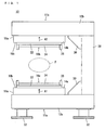
- a magnetic field generator 10 is an open-type, permanent-magnet-type magnetic field generator for MRI, and includes a pair of magnetic pole units 11a and 11b opposed to each other with a space in between.
- the magnetic pole units 11a and 11b include plate yokes 12a and 12b respectively.
- the pair of plate yokes 12a and 12b have opposed surfaces provided with permanent magnet groups 14a and 14b respectively.
- the permanent magnet groups 14a and 14b have opposed surfaces (first main surfaces) provided with pole pieces 16a and 16b respectively.
- the permanent magnet group 14a has the first main surface and a second main surface provided with the pole piece 16a and the plate yoke 12a respectively.
- the permanent magnet group 14b has the first main surface and a second main surface provided with the pole piece 16b and the plate yoke 12b respectively.
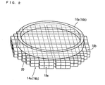
- each of the permanent magnet groups 14a and 14b is made of a plurality of cubic or rectangular parallelepiped permanent magnets 20 bonded together into a one-piece component, which has a zigzag (stepped) outer circumferential surface 18a.
- the permanent magnets 20 in the permanent magnet group 14a have their direction of magnetization aligned in Arrow A1 Direction whereas the permanent magnets 20 in the permanent magnet group 14b have their direction of magnetization aligned in Arrow A2 Direction. Therefore, the permanent magnet group 14a has its N pole on its first main surface (the surface opposing to the permanent magnet group 14b) whereas the permanent magnet group 14b has its S pole on its first main surface (the surface opposing to the permanent magnet group 14a).
- the permanent magnets 20 are provided by a high magnetic flux density type R-Fe-B sintered magnet (R is provided by one of the rare-earth elements including Y) such as NEOMAX-47 (manufactured by Hitachi Metals, Ltd).
- the permanent magnets 20 are obtained by assembling unillustrated unit magnets.
- the pole piece 16a is provided in the first main surface of the permanent magnet group 14a, leaving an exposed region 18b in the first main surface of the permanent magnet group 14a.
- the pole piece 16b is provided in the first main surface of the permanent magnet group 14b, leaving an exposed region 18b in the first main surface of the permanent magnet group 14b.
- the exposed regions 18b are regions which are left exposed in the first main surfaces of the permanent magnet groups 14a, 14b when the pole pieces 16a, 16b are provided in the first main surfaces of the permanent magnet groups 14a, 14b respectively.
- the pole piece 16a includes a disc-shaped base plate 22 which is made of iron for example and is disposed on the first main surface of the permanent magnet group 14a.
- a silica steel sheet 24 is formed to prevent generation of eddy current.
- the silica steel sheet 24 is fixed on the base plate 22 with adhesive.
- the base plate 22 has a circumferential edge portion formed with an annular projection 26 made of iron for example, for increased magnetic field intensity around the edge portion to obtain a uniform magnetic field.
- the pole piece 16b has the same configuration as the pole piece 16a.
- the plate yokes 12a and 12b are magnetically connected by a platy support yoke 28.
- the support yoke 28 is connected with the plate yokes 12a and 12b, so that the support yoke 28 has its lower end surface placed along an edge of an end on an upper surface of the plate yoke 12a, while the support yoke 28 has its upper end surface placed along an edge of an end on a lower surface of the plate yoke 12b. Therefore, the plate yokes 12a and 12b and the support yoke 28 are connected at an approximately 90 degree angle, to form a U shape when viewed from a side.
- reinforcing members 30 are provided on an inner surface which is made as a result of connecting the plate yoke 12a and the support yoke 28, at the farthest position therein from the permanent magnet group 14a (i.e. at both ends of the inner surface area which is made by the plate yoke 12a and the support yoke 28, according to the present embodiment).
- reinforcing members 30 are provided on an inner surface which is made as a result of connecting the plate yoke 12b and the support yoke 28.
- the plate yoke 12a has a lower surface provided with four leg members 32.
- a magnetic field is generated on the first-main-surface side of the permanent magnet groups 14a and 14b, i.e. in a space between the pole pieces 16a and 16b, and it is required that a magnetic field intensity in a uniform magnetic field space F (see Fig. 1 ) is not lower than 0.2 T.
- the magnetic pole unit 11a includes a frame-like member 34 which is provided to surround the permanent magnet group 14a; and a flange-shaped member 36 which is provided to cover the exposed region 18b of the permanent magnet group 14a.
- Fig. 3 does not show the magnetic pole unit 11b. Obviously however, the magnetic pole unit 11b has an up-down symmetrical structure with respect to the magnetic pole unit 11a.
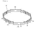
- the frame-like member 34 includes a plurality (four in this embodiment) of frame-like member pieces 34a.
- Each of the frame-like member pieces 34a has a zigzag shape following its corresponding portion of the outer circumferential surface 18a (see Fig. 2 ) of the permanent magnet group 14a. Therefore, the frame-like member 34 as a whole has a zigzag shape following the outer circumferential surface 18a of the permanent magnet group 14a.
- Each frame-like member piece 34a is made of a non-magnetic material (non-magnetic metal) such as aluminum and stainless steel, having a thickness of approximately 1 mm through 10 mm.
- Each frame-like member piece 34a includes a plurality of bolt holes 38 penetrating the piece from the outer side (the side away from the permanent magnet group 14a) to the inner side (the side opposing to the permanent magnet group 14a); and platy mounting portions 39a for mounting the frame-like member piece 34a to the plate yoke 12a.
- Each frame-like member piece 34a is disposed in contact with the outer circumferential surface 18a of the permanent magnet group 14a, and then has its mounting portions 39 fastened to the plate yoke 12a with unillustrated fixing members such as bolts, whereby each frame-like member piece 34a is fixed to the plate yoke 12a.
- the frame-like member 34 which is a dividable structure has a following advantage for example: When magnetic field adjustment is made by adding a permanent magnet(s), a magnetic member (s) or a non-magnetic member (s) to the permanent magnet group 14a, and the adjustment has altered the shape of the outer circumferential surface 18a, such an alteration can easily be dealt with by replacing only part of the frame-like member piece 34a.
- the flange-shaped member 36 is provided in an outer circumferential surface of the pole piece 16a, to cover the exposed region 18b (see Fig. 2 ) of the permanent magnet group 14a.
- the flange-shaped member 36 includes a plurality (eight in this embodiment) of flange-shaped member pieces 36a each having a generally L-shaped vertical section and an arcuate shape in a plan view.
- Each of the flange-shaped member pieces 36a is made of a non-magnetic material such as aluminum and stainless steel, has a thickness of approximately 1 mm through 10 mm, and includes a first portion 37a opposed to the exposed region 18b of the permanent magnet group 14a; and a second portion 37b opposed to the outer circumferential surface of the pole piece 16a.
- the first portion 37a in each flange-shaped member piece 36a includes a plurality of bolt holes 40 penetrating the portion from the upper side through the lower side.
- the first portion 37a is disposed in contact with the exposed region 18b of the permanent magnet group 14a, and the second portion 37b is fastened to an outer circumferential surface of the pole piece 16a with unillustrated fixing members such as bolts or by welding, etc., whereby each flange-shaped member piece 36a is provided on the outer circumferential surface of the pole piece 16a.
- flange-shaped member 36 which is a dividable structure has an advantage of reduced eddy current generated in the flange-shaped member 36 and therefore reduced adverse influence to the uniform magnetic field space F. If the eddy current reduction has a higher importance, a member which has a high electrical resistance may be disposed, or a gap may be provided, between the pole piece 16a and each flange-shaped member piece 36a, as well as between two mutually adjacent flange-shaped member pieces 36a, to isolate them.
- an inspection is made to the plate yoke 12a with the frame-like member 34 mounted thereto, to see if there is any gap between the outer circumferential surface 18a of the permanent magnet group 14a and the frame-like member 34.
- an insertion member 42 is inserted to any relatively large gap found between the outer circumferential surface 18a and the frame-like member 34.
- the insertion member 42 thus inserted is then pressed to the outer circumferential surface 18a with a presser bolt 44 which is threaded into the bolt hole 38 of the frame-like member 34.
- the outer circumferential surface 18a is pressed by the presser bolt 44 via the insertion member 42. If the gap found between the outer circumferential surface 18a and the frame-like member 34 is too small to insert the insertion member 42, the outer circumferential surface 18a is pressed directly by the presser bolt 44.
- a platy insertion member 46 is inserted to any relatively large gap found between the exposed region 18b and the flange-shaped member 36.
- the insertion member 46 thus inserted is then pressed to the exposed region 18b with a presser bolt 48 which is threaded into the bolt hole 40 of the flange-shaped member 36.
- the exposed region 18b is pressed by the presser bolt 48 via the insertion member 46. If the gap found between the exposed region 18b and the flange-shaped member 36 is too small to insert the insertion member 46, the exposed region 18b is pressed directly by the presser bolt 48.
- the insertion members 42 and 46, as well as the pressing members provided by the presser bolts 44 and 48 are each made of non-magnetic material such as aluminum and stainless steel.
- the platy insertion member 42 has specific dimensions (area of main surfaces and thickness) and a shape selected in accordance with the gaps between the outer circumferential surface 18a and the frame-like member 34.
- the presser bolts 44 and 48 are provided by, for example, an M6 check bolt which has a hexagon hole.
- the presser bolt 44 is threaded into the frame-like member 34 using an unillustrated torque wrench, threaded through the frame-like member 34, and then pressed to the insertion member 42 or the outer circumferential surface 18a.
- the presser bolt 48 is threaded into the flange-shaped member 36 using a torque wrench, threaded through the flange-shaped member 36, and then pressed to the insertion member 46 or the exposed region 18b. In this step, it is preferable that the presser bolts 44 and 48 are torqued to approximately 2.5 N ⁇ m. Using the torque value as mentioned above makes sure that the permanent magnets 20 are pressed sufficiently while preventing deformation of the frame-like member 34 or the flange-shaped member 36 as well as damage to the permanent magnets 20.
- magnetic insertion members 42 and 46, and the presser bolts 44 and 48 account for only a small percentage in (the volume of) the entire magnetic pole unit 11a, then magnetic insertion members 42 and 46, and presser bolts 44 and 48 made of a magnetic material such as iron, may be used partially (selectively).
- the insertion members 42 and 46 as well as the presser bolts 44 and 48 which are made of magnetic material serve as magnetic field adjustment members for obtaining a desired magnetic field in the uniform magnetic field space F, making it possible to improve the magnetic field intensity and/or magnetic field uniformity.
- the magnetic pole unit 11b Like the magnetic pole unit 11a, the magnetic pole unit 11b includes a frame-like member 34, a flange-shaped member 36, insertion members 42 and 46, and presser bolts 44 and 48. No description will be made here for these members in the magnetic pole unit 11b.
- the magnetic field generator 10 even if there is a gap between the outer circumferential surface 18a and the frame-like member 34, it is possible to press the outer circumferential surface 18a or the insertion member 42 with the presser bolt 44 which is threaded into the frame-like member 34, whereby separation and dislocation of the permanent magnets 20 toward the outer circumferential surface 18a can be prevented easily and reliably. Also, even if there is a gap between the exposed region 18b and the flange-shaped member 36, it is possible to press the exposed region 18b or the insertion member 46 with the presser bolt 48 which is threaded into the flange-shaped member 36, whereby separation and dislocation of the permanent magnets 20 toward the exposed region 18b can be prevented easily and reliably.
- the invention can prevent image quality deterioration. Also, the invention can improve productivity since it is easy to prevent separation and dislocation of the permanent magnets 20 from the permanent magnet groups 14a and 14b without preparing custom-made permanent magnet fixing members, etc. to fit to unique shapes of individual permanent magnet groups 14a and 14b for each apparatus.
- Permanent magnets 20 placed side by side in the lateral direction are under a strong repulsion force constantly.
- the invention is capable of reducing the burden, in terms of the strength, of the adhesive which is used to fix the permanent magnets 20.
- a single presser bolt 44 can stably press a large area of the outer circumferential surface 18a.
- a single presser bolt 48 can stably press a large area of the exposed region 18b. The invention therefore prevents separation and dislocation of the permanent magnets 20 from the permanent magnet groups 14a and 14b more reliably while reducing the number of the presser bolts 44 and 48.
- the invention prevents damage to the permanent magnets 20. Further, the insertion members 42 and 46 can fill or reduce gaps between the frame-like member 34 and the permanent magnet groups 14a, 14b, and gaps between the flange-shaped member 36 and the permanent magnet groups 14a, 14b, making it possible to further simplify the shape of the frame-like member 34 and the flange-shaped member 36.
- the invention provides an easy and reliable solution for preventing separation and dislocation of the permanent magnets 20 toward the outer circumferential surface 18a, while making it possible to improve productivity. It is easy to find any relatively large gaps between the outer circumferential surface 18a and the frame-like member 34. Only a short glance is required to determine where to dispose the insertion members 42.
- the invention provides an easy and reliable solution for preventing separation and dislocation of the permanent magnets 20 toward the exposed region 18b, while making it possible to improve productivity. It is easy to find any relatively large gaps between the exposed region 18b and the flange-shaped member 36. Only a short glance is required to determine where to dispose the insertion members 46.
- the cover members provided by the frame-like member 34 and the flange-shaped member 36 are made of non-magnetic material.
- the invention prevents separation and dislocation of the permanent magnets 20 from the permanent magnet group 14a and 14b without causing adverse influence to the intended magnetic field.
- the invention makes it possible to adjust the magnetic field in the uniform magnetic field space F, and to improve magnetic field intensity and/or magnetic field uniformity.
- each of the presser bolts 44 and 48 is locked by an anti-loosening member.
- an adhesive or other anti-loosening agent may be applied to the presser bolts 44 and 48 or the bolt holes 38 and 40, or a locknut etc. may be threaded around the presser bolts 44 and 48, to eliminate loosening of the presser bolts 44 and 48.
- cyanoacrylate adhesives used as quick setting adhesives are high in peeling strength but low in impact resistance and heat resistance. This can lead to an earlier deterioration even if the adhesives are stored in room temperatures.
- quick setting adhesive by combining quick setting adhesive with the present invention, it becomes possible to fix the permanent magnets which are included in a magnetic field generator for a long period of time.
- Fig. 3 and Fig. 5 show a state where all of the bolt holes 38 are threaded by the presser bolts 44, and all of the bolt holes 40 are threaded by the presser bolts 48.
- the presser bolts 44 or 48 may be threaded into only those holes located at places which require pressing on the outer circumferential surface 18a, the exposed region 18b and the insertion members 42 and 46.
- each frame-like member 34 is sized to surround a corresponding one of the permanent magnet groups 14a and 14b together with the insertion members 42 attached thereto.
- the present invention is not limited to this.
- the insertion members 46 are bonded to the permanent magnet groups 14a and 14b to cover the exposed region 18b, and then the flange-shaped member 36 is provided on the permanent magnet groups 14a and 14b.
- the frame-like member 34 faces the entire outer circumferential surface 18a.
- the frame-like member is not limited to this.
- the frame-like member may be opposed only to part of the outer circumferential surface of the permanent magnet group.
- the frame-like member may be constituted by one frame-like member piece 34a.
- the frame-like member is not limited to this.
- the flange-shaped member may cover only part of the exposed region of the permanent magnet group.
- the flange-shaped member may be constituted by one flange-shaped member piece 36a.
- the frame-like members 34 and the flange-shaped members 36 are provided as the cover members.
- one of the two kinds, i.e., the frame-like members 34 or the flange-shaped members 36 may not be provided.
- cover members are not limited to these.
- a plate-like member 50 as shown in Fig. 6 may be fixed as the cover member to a desired position around the permanent magnet group 14a and 14b with unillustrated fixing members such as a bolt.
- the plate-like member 50 is provided to partially cover the permanent magnet groups 14a and 14b.
- plate-like members 50a, 50b to be described later are provided to partially cover the permanent magnet groups 14a and 14b.
- the plate-like member 50 is a platy member which has been bent twice and has a first flat portion 52, a second flat portion 54 and a third flat portion 56.
- the first flat portion 52 is opposed to surfaces (indicated by a reference symbol "20a") which make the outer circumferential surface 18a (see Fig. 2 ) in the permanent magnets 20.
- the second flat portion 54 is opposed to surfaces (indicated by a reference symbol "20b") which make the exposed region 18b (see Fig. 2 ) in the permanent magnets 20.
- the third flat portion 56 is fixed to the plate yoke 12a or 12b (see Fig. 1 ).
- the first flat portion 52 includes a plurality (four in this embodiment) of bolt holes 58 penetrating the portion from the outer side (the side away from the permanent magnets 20) to the inner side (the side opposing to the permanent magnets 20).
- the second flat portion 54 includes a plurality (two in this embodiment) of bolt holes 60 penetrating the portion from the upper side to the lower side.
- Platy insertion members 62 are inserted into a gap between the surfaces 20a of the permanent magnets 20 and the first flat portion 52.
- the insertion members 62 are pressed onto the surfaces 20a of the permanent magnets 20 with presser bolts 64 threaded into the bolt holes 58.
- the insertion members 62 are pressed onto the outer circumferential surfaces 18a (see Fig. 2 ) of the permanent magnet groups 14a and 14b.
- platy insertion members 66 are inserted into a gap between the surfaces 20b of the permanent magnets 20 and the second flat portion 54.
- the insertion members 66 are pressed onto the surfaces 20b of the permanent magnets 20 with presser bolts 68 threaded into the bolt holes 60.
- the insertion members 66 are pressed onto the exposed regions 18b (see Fig. 2 ) of the permanent magnet groups 14a and 14b.
- a plate-like member 50a which does not have bolt holes 58 in the first flat portion 52 may be used, with the first flat portion 52 bonded directly to the surfaces 20a of the permanent magnets 20.
- separation and dislocation of the permanent magnets 20 toward the outer circumferential surface 18a can be prevented without the use of the insertion member 62 or the presser bolt 64.
- a plate-like member 50b which does not have bolt holes 60 in the second flat portion 54 may be used, with the second flat portion 54 bonded directly to the surfaces 20b of the permanent magnets 20.
- separation and dislocation of the permanent magnets 20 toward the exposed region 18b can be prevented without the use of the insertion member 66 or the presser bolt 68.
- the permanent magnets 20 are pressed directly by the presser bolts 68.
- the gap between the surface 20a and the first flat portion 52 is too small to insert the insertion member 66 in a case of using the plate-like member 50 or 50b, it is preferable that the permanent magnets 20 are pressed directly by the presser bolts 64.
- insertion members 70 may be blocks which have a triangular or rectangular section in a plan view.
- the cover member is provided by a frame-like member 72 which includes a plurality of platy (like a flat plate) frame-like member pieces 72a, and the insertion members 70 are pressed onto the outer circumferential surface 18a by presser bolts 74 threaded through the frame-like member pieces 72a.
- the frame-like member 72 which includes platy (flat-plate-like) frame-like member pieces 72a as described are easy to obtain and can be utilized commonly.
- placements of the frame-like member pieces 72a and shapes of the block-like insertion members 70 are designed so that the presser bolts 74 make their contact approximately perpendicularly to the surface of the corresponding insertion members 70.
- the frame-like member piece 34a may be formed with various reinforcing members 76a through 76e as shown in Fig. 9 .
- the reinforcing member 76a is a strip-like top plate provided at an upper portion of the frame-like member piece 34a.
- the reinforcing member 76b is a triangular top plate provided at an upper corner portion of the frame-like member piece 34a.
- the reinforcing member 76c is a triangular bottom plate provided at a lower corner portion of the frame-like member piece 34a.
- the reinforcing member 76d is a plate-like member provided on a side surface of the frame-like member piece 34a.
- the reinforcing member 76e is an L-shaped member provided to abut on a side surface of the frame-like member piece 34a and on the plate yoke 12a or 12b.
- the reinforcing member 76e is fixed to the plate yoke 12a or 12b with unillustrated fixing members such as bolts.
- the reinforcing members 76a through 76e may be formed onto the frame-like member piece 34a by means of welding for example.
- the reinforcing members 76a through 76e formed on the frame-like member piece 34a increase strength of the frame-like member 34a when withstanding the repulsion force from the permanent magnet groups 14a, 14b exerted to the pressing members, preventing separation or dislocation of the permanent magnets 20 from the permanent magnet groups 14a, 14b more effectively.
- Providing the reinforcing members 76a through 76e in the frame-like member piece 34a as shown in Fig. 9 i. e. , in vicinity of a long flat surface portion 34b is particularly effective. It should be noted here that the arrangement requires that at least one of the reinforcing members 76a through 76e is formed in the frame-like member piece 34a.
- the pressing member may be provided by a presser bolt which has an increased diameter at an end portion that makes contact with the permanent magnet group.
- the pressing member may be provided by a bolt which has a head, that the bolt is threaded to the cover member in advance so that its head will face the permanent magnet group.
- the permanent magnet group is pressed by the head of the bolt.
- the other end of the bolt away from the head is formed with a hole for fitting a hexagonal wrench or a groove for fitting a screw driver. With such an arrangement, the bolt can be threaded easily.
- the pressing member may be provided by a pair of a bolt and a nut, so that the bolt is threaded in the cover member and the nut is then threaded around the end of the bolt to face the permanent magnet group.
- the permanent magnet group can be pressed by the nut.
- the yoke is constituted by the plate yokes 12a, 12b and a support yoke 28.
- the present invention is not limited to this.
- a C-shaped, integrated yoke which connects a pair of permanent magnet groups 14a, 14b magnetically may be used.
- the magnetic pole units 11a and 11b are provided with the permanent magnet groups 14a and 14b respectively.
- the present invention is not limited to this.
- the magnetic pole unit 11b may not be provided with the permanent magnet group 14b.
- cover members frame-like member, flange-shaped member
- the pressing members and the insertion members which constitute the present invention can be retrofitted to conventional magnetic field generators which do not have these constitutional members.
- cover members frame-like member, flange-shaped member
- the pressing members and the insertion members which constitute the present invention can be retrofitted to conventional magnetic field generators which do not have these constitutional members.
Landscapes
- Physics & Mathematics (AREA)
- Condensed Matter Physics & Semiconductors (AREA)
- General Physics & Mathematics (AREA)
- Magnetic Resonance Imaging Apparatus (AREA)
Abstract
Description
- The present invention relates to magnetic field generators, and more specifically to permanent-magnet type magnetic field generators.
- Conventionally, in permanent magnet type magnetic field generators used for MRI (Magnetic Resonance Imaging) etc., permanent magnets which constitute a permanent magnet group are bonded to adjacent permanent magnets, a plate yoke or both of these with adhesive. Patent Document 1 discloses a technique for preventing separation of the permanent magnets from the permanent magnet group in the permanent magnet type magnetic field generators.
Patent Document 1:JP-A 2004-358097 - Permanent magnets which constitute a permanent magnet group are subject to size variation due to machining accuracy of machining equipment or due to sintering operation if the permanent magnets are sintered products. Therefore, the permanent magnet group is also subject to shape and size variation. For example, if permanent magnets have a size variation of approximately 0.1 mm per magnet, a permanent magnet group which includes twenty of the permanent magnets in its width direction, can have a maximum of approximately 2 mm difference in the width of the permanent magnet group. Also, there is variation in the thickness of adhesive layers which bond the permanent magnets to adjacent permanent magnets or the plate yoke, and this is another cause for the size variation in the permanent magnet group.
- In order to achieve more reliable separation prevention of the permanent magnets, the technique in Patent Document 1 requires a set of custom-made permanent magnet fixing members etc., made to the shapes and sizes of individual permanent magnet groups in each apparatus. In magnetic field generators for use in MRI, a large number of permanent magnets are used in the permanent magnet groups. As a result, variation in the shape and the size of the permanent magnet groups tends to be large, and the need for custom-made permanent magnet fixing members are especially high. However, custom-made permanent magnet fixing members require a substantial amount of time to manufacture, resulting in decreased productivity in the manufacture of the apparatus.
- Also, in a long run (typically no less than ten years), permanent magnet type magnetic field generators for MRI are subject to problems due to the age. Oxidization of the permanent magnets, deterioration of the adhesive, vibration and impact for example, can break bonding between the permanent magnets or between permanent magnets and the plate yokes, resulting in dislocation of the permanent magnets. Especially, in cases where the permanent magnets are provided by an R-Fe-B sintered magnet (R is provided by one of the rare-earth elements including Y) which has superb magnetic characteristics, there is an increased risk of the problem of permanent magnet dislocation since the magnet of this type contains a rare-earth element and iron, can be oxidized more easily and lose some of its bonding performance if stored in a high-temperature, high-humidity environment. In magnetic field generators, a 1 mm dislocation of a permanent magnet in its permanent magnet group results in approximately a 40 ppm change in magnetic field intensity in a uniform magnetic field space inside the magnetic field generator. Such a change, even as small as 40 ppm, affects MRI imaging performance for example, and a result is decreased quality of image.
- Therefore, a primary object of the present invention is to provide a magnetic field generator in which separation and dislocation of permanent magnets from their permanent magnet groups is prevented easily and reliably for a long period of time without sacrificing productivity.
- According to an aspect of the present invention, there is provided a magnetic field generator which includes a permanent magnet group having a plurality of permanent magnets bonded together, for generation of a magnetic field on a first main-surface side of the permanent magnet group; a cover member provided along the permanent magnet group; and a pressing member provided in the cover member for pressing the permanent magnet group.
- In the present invention, even if there is a gap between the permanent magnet group and the cover member, it is possible to press the permanent magnet group with the pressing member provided in the cover member, whereby the permanent magnets are fixed strongly and therefore separation and dislocation of the permanent magnets from the permanent magnet group is prevented easily and reliably for a long period of time. Hence, it is possible to prevent image quality deterioration caused by dislocation of permanent magnets in the permanent magnet group. By using the pressing member as described, it becomes easy to solve the problem of shape and size variation in the permanent magnet group. Also, the invention can improve productivity since it is easy to prevent separation and dislocation of the permanent magnets from the permanent magnet group without preparing a custom-made permanent magnet fixing member etc., to fit to a unique shape and size of an individual permanent magnet group for each apparatus.
- Preferably, the magnetic field generator further includes an insertion member for insertion into a gap between the permanent magnet group and the cover member, and the pressing member presses the permanent magnet group via the insertion member. In this case, the insertion member is inserted into a relatively large gap between the permanent magnet group and the cover member, and the insertion member is pressed to the permanent magnet group by the pressing member. In other words, the pressing member presses the permanent magnet group via the insertion member. By using the insertion member in between, it becomes possible to press a large area of the permanent magnet group stably with a single pressing member, and to prevent separation and dislocation of the permanent magnets from the permanent magnet group more reliably while reducing the number of the pressing members. Also, by placing the insertion member in between, the invention prevents damage to the permanent magnets. Further, the insertion member can fill or reduce the gap between the permanent magnet group and the cover member. This eliminates the need for custom-made permanent magnet fixing members, etc. to fit to unique shapes and sizes of individual permanent magnet groups for each apparatus, making it possible to further simplify the shape of the cover member.
- Further preferably, the cover member includes a frame-like member provided to surround the permanent magnet group, and the pressing member is provided in the frame-like member. In this case, the permanent magnet group is pressed from an outer circumferential surface side, by the pressing member which is provided in the frame-like member. By using the frame-like member which surrounds the permanent magnet group, as the cover member, the invention provides easy and reliable solution for preventing separation and dislocation of the permanent magnets toward the outer circumferential surface of the permanent magnet group, making it possible to improve productivity.
- Further, preferably, the magnetic field generator further includes a pole piece provided in the first main surface of the permanent magnet group while leaving an exposed region in the first main surface. In this arrangement, the cover member includes a flange-shaped member provided in an outer circumferential surface of the pole piece to cover the exposed region of the permanent magnet group, and the pressing member is provided in the flange-shaped member. In this case, the permanent magnet group is pressed from an exposed-region side, by the pressing member which is provided in the flange-shaped member. By using the flange-shaped member which is provided to cover the exposed region, as the cover member, the invention provides easy and reliable solution for preventing separation and dislocation of the permanent magnets toward the exposed region of the permanent magnet group, making it possible to improve productivity.
- Preferably, the cover member is a non-magnetic member. The cover member provided by a non-magnetic member makes it possible to prevent separation and dislocation of the permanent magnets from the permanent magnet group without causing adverse influence to the intended magnetic field.
- The above-described object and other objects, characteristics, aspects and advantages of the present invention will become clearer from the following detailed description of embodiments of the present invention with reference to the attached drawings.
-
-
Fig. 1 is a schematic side view of a magnetic field generator to which the present invention is applied. -
Fig. 2 is a perspective view showing an example of a permanent magnet group and a pole piece. -
Fig. 3 is a partial perspective view showing a magnetic field generator including a frame-like member and a flange-shaped member. -
Fig. 4 is an exploded perspective view of the frame-like member. -
Fig. 5 shows states where insertion members are inserted into gaps between the permanent magnet group and a cover member;Fig. 5 (a) is a plan view showing a state where insertion members are inserted into gaps between an outer circumferential surface and a frame-like member whereasFig. 5 (b) is a side view showing a state where insertion members are inserted into gaps between an exposed region and a flange-shaped member. -
Fig. 6 is a perspective view showing another example of cover member. -
Fig. 7 is a perspective view showing still another example of cover member. -
Fig. 8 is a plan view showing a case where a block-shaped insertion member is used. -
Fig. 9 is a perspective view showing an example of reinforcing members. -
- 10
- Magnetic field generator
- 11a, 11b
- Magnetic pole units
- 12a, 12b
- Plate yokes
- 14a, 14b
- Permanent magnet groups
- 16a, 16b
- Pole pieces
- 18a
- Outer circumferential surface of permanent magnet group
- 18b
- Exposed region in permanent magnet group
- 20
- Permanent magnet
- 34, 72
- Frame-like members
- 36
- Flange-shaped member
- 42, 46, 62, 66, 70
- Insertion members
- 44, 48, 64, 68, 74
- Presser bolts
- 50, 50a, 50b
- Plate-like members
- Hereinafter, embodiments of the present invention will be described with reference to the drawings.
Referring toFig. 1 , amagnetic field generator 10 according to an embodiment of the present invention is an open-type, permanent-magnet-type magnetic field generator for MRI, and includes a pair ofmagnetic pole units - The
magnetic pole units plate yokes plate yokes permanent magnet groups permanent magnet groups pole pieces permanent magnet group 14a has the first main surface and a second main surface provided with thepole piece 16a and theplate yoke 12a respectively. Thepermanent magnet group 14b has the first main surface and a second main surface provided with thepole piece 16b and theplate yoke 12b respectively. - Referring also
Fig. 2 , each of thepermanent magnet groups permanent magnets 20 bonded together into a one-piece component, which has a zigzag (stepped) outercircumferential surface 18a. - In the
permanent magnet group 14a, allpermanent magnets 20 are disposed in the same direction of magnetization, and in thepermanent magnet group 14b, allpermanent magnet 20 are disposed in the same direction of magnetization. As shown inFig. 1 , in this embodiment, thepermanent magnets 20 in thepermanent magnet group 14a have their direction of magnetization aligned in Arrow A1 Direction whereas thepermanent magnets 20 in thepermanent magnet group 14b have their direction of magnetization aligned in Arrow A2 Direction. Therefore, thepermanent magnet group 14a has its N pole on its first main surface (the surface opposing to thepermanent magnet group 14b) whereas thepermanent magnet group 14b has its S pole on its first main surface (the surface opposing to thepermanent magnet group 14a). - The
permanent magnets 20 are provided by a high magnetic flux density type R-Fe-B sintered magnet (R is provided by one of the rare-earth elements including Y) such as NEOMAX-47 (manufactured by Hitachi Metals, Ltd). Thepermanent magnets 20 are obtained by assembling unillustrated unit magnets. - As shown in
Fig. 1 andFig. 2 , thepole piece 16a is provided in the first main surface of thepermanent magnet group 14a, leaving an exposedregion 18b in the first main surface of thepermanent magnet group 14a. Likewise, thepole piece 16b is provided in the first main surface of thepermanent magnet group 14b, leaving an exposedregion 18b in the first main surface of thepermanent magnet group 14b. The exposedregions 18b are regions which are left exposed in the first main surfaces of thepermanent magnet groups pole pieces permanent magnet groups - As shown in
Fig. 1 , thepole piece 16a includes a disc-shapedbase plate 22 which is made of iron for example and is disposed on the first main surface of thepermanent magnet group 14a. On thebase plate 22, asilica steel sheet 24 is formed to prevent generation of eddy current. Thesilica steel sheet 24 is fixed on thebase plate 22 with adhesive. Thebase plate 22 has a circumferential edge portion formed with anannular projection 26 made of iron for example, for increased magnetic field intensity around the edge portion to obtain a uniform magnetic field. Thepole piece 16b has the same configuration as thepole piece 16a. - The plate yokes 12a and 12b are magnetically connected by a
platy support yoke 28. Specifically, thesupport yoke 28 is connected with the plate yokes 12a and 12b, so that thesupport yoke 28 has its lower end surface placed along an edge of an end on an upper surface of theplate yoke 12a, while thesupport yoke 28 has its upper end surface placed along an edge of an end on a lower surface of theplate yoke 12b. Therefore, the plate yokes 12a and 12b and thesupport yoke 28 are connected at an approximately 90 degree angle, to form a U shape when viewed from a side. - Referring also to
Fig. 3 , reinforcingmembers 30 are provided on an inner surface which is made as a result of connecting theplate yoke 12a and thesupport yoke 28, at the farthest position therein from thepermanent magnet group 14a (i.e. at both ends of the inner surface area which is made by theplate yoke 12a and thesupport yoke 28, according to the present embodiment). Likewise, reinforcingmembers 30 are provided on an inner surface which is made as a result of connecting theplate yoke 12b and thesupport yoke 28. Also, theplate yoke 12a has a lower surface provided with fourleg members 32. - In the
magnetic field generator 10 as described, a magnetic field is generated on the first-main-surface side of thepermanent magnet groups pole pieces Fig. 1 ) is not lower than 0.2 T. - As shown in
Fig. 3 , in themagnetic field generator 10, themagnetic pole unit 11a includes a frame-like member 34 which is provided to surround thepermanent magnet group 14a; and a flange-shapedmember 36 which is provided to cover the exposedregion 18b of thepermanent magnet group 14a. - It should be noted here that
Fig. 3 does not show themagnetic pole unit 11b. Obviously however, themagnetic pole unit 11b has an up-down symmetrical structure with respect to themagnetic pole unit 11a. - As shown in
Fig. 4 , the frame-like member 34 includes a plurality (four in this embodiment) of frame-like member pieces 34a. Each of the frame-like member pieces 34a has a zigzag shape following its corresponding portion of the outercircumferential surface 18a (seeFig. 2 ) of thepermanent magnet group 14a. Therefore, the frame-like member 34 as a whole has a zigzag shape following the outercircumferential surface 18a of thepermanent magnet group 14a. Each frame-like member piece 34a is made of a non-magnetic material (non-magnetic metal) such as aluminum and stainless steel, having a thickness of approximately 1 mm through 10 mm. Each frame-like member piece 34a includes a plurality of bolt holes 38 penetrating the piece from the outer side (the side away from thepermanent magnet group 14a) to the inner side (the side opposing to thepermanent magnet group 14a); and platy mounting portions 39a for mounting the frame-like member piece 34a to theplate yoke 12a. Each frame-like member piece 34a is disposed in contact with the outercircumferential surface 18a of thepermanent magnet group 14a, and then has its mountingportions 39 fastened to theplate yoke 12a with unillustrated fixing members such as bolts, whereby each frame-like member piece 34a is fixed to theplate yoke 12a. - Using the frame-
like member 34 which is a dividable structure has a following advantage for example: When magnetic field adjustment is made by adding a permanent magnet(s), a magnetic member (s) or a non-magnetic member (s) to thepermanent magnet group 14a, and the adjustment has altered the shape of the outercircumferential surface 18a, such an alteration can easily be dealt with by replacing only part of the frame-like member piece 34a. - As shown in
Fig. 3 , the flange-shapedmember 36 is provided in an outer circumferential surface of thepole piece 16a, to cover the exposedregion 18b (seeFig. 2 ) of thepermanent magnet group 14a. The flange-shapedmember 36 includes a plurality (eight in this embodiment) of flange-shapedmember pieces 36a each having a generally L-shaped vertical section and an arcuate shape in a plan view. Each of the flange-shapedmember pieces 36a is made of a non-magnetic material such as aluminum and stainless steel, has a thickness of approximately 1 mm through 10 mm, and includes afirst portion 37a opposed to the exposedregion 18b of thepermanent magnet group 14a; and asecond portion 37b opposed to the outer circumferential surface of thepole piece 16a. Thefirst portion 37a in each flange-shapedmember piece 36a includes a plurality of bolt holes 40 penetrating the portion from the upper side through the lower side. Thefirst portion 37a is disposed in contact with the exposedregion 18b of thepermanent magnet group 14a, and thesecond portion 37b is fastened to an outer circumferential surface of thepole piece 16a with unillustrated fixing members such as bolts or by welding, etc., whereby each flange-shapedmember piece 36a is provided on the outer circumferential surface of thepole piece 16a. - Using the flange-shaped
member 36 which is a dividable structure has an advantage of reduced eddy current generated in the flange-shapedmember 36 and therefore reduced adverse influence to the uniform magnetic field space F. If the eddy current reduction has a higher importance, a member which has a high electrical resistance may be disposed, or a gap may be provided, between thepole piece 16a and each flange-shapedmember piece 36a, as well as between two mutually adjacent flange-shapedmember pieces 36a, to isolate them. - Even if the frame-
like member 34 is provided in contact with the outercircumferential surface 18a of thepermanent magnet group 14a as mentioned earlier, there is still a chance for gaps between the outercircumferential surface 18a and the frame-like member 34. Likewise, even if the flange-shapedmember 36 is provided in contact with the exposedregion 18b of thepermanent magnet group 14a, there is still a chance for gaps between the exposedregion 18b and the flange-shapedmember 36. This is due to size variation of thepermanent magnets 20 which are provided by rare-earth sintered magnets for example. Due to technical limitation to make thesepermanent magnets 20 exactly to a predetermined size, and due to variation in the thickness of adhesive layer, thepermanent magnet group 14a can have stepped surfaces which are not as smooth as ideal. - As a solution, an inspection is made to the
plate yoke 12a with the frame-like member 34 mounted thereto, to see if there is any gap between the outercircumferential surface 18a of thepermanent magnet group 14a and the frame-like member 34. Then, as shown inFig. 5 (a) , aninsertion member 42 is inserted to any relatively large gap found between the outercircumferential surface 18a and the frame-like member 34. Theinsertion member 42 thus inserted is then pressed to the outercircumferential surface 18a with apresser bolt 44 which is threaded into thebolt hole 38 of the frame-like member 34. In other words, the outercircumferential surface 18a is pressed by thepresser bolt 44 via theinsertion member 42. If the gap found between the outercircumferential surface 18a and the frame-like member 34 is too small to insert theinsertion member 42, the outercircumferential surface 18a is pressed directly by thepresser bolt 44. - Likewise, an inspection is made to the
pole piece 16a with the flange-shapedmember 36 mounted thereto, to see if there is any gap between the exposedregion 18b of thepermanent magnet group 14a and the flange-shapedmember 36. Then, as shown inFig. 5(b) , aplaty insertion member 46 is inserted to any relatively large gap found between the exposedregion 18b and the flange-shapedmember 36. Theinsertion member 46 thus inserted is then pressed to the exposedregion 18b with apresser bolt 48 which is threaded into thebolt hole 40 of the flange-shapedmember 36. In other words, the exposedregion 18b is pressed by thepresser bolt 48 via theinsertion member 46. If the gap found between the exposedregion 18b and the flange-shapedmember 36 is too small to insert theinsertion member 46, the exposedregion 18b is pressed directly by thepresser bolt 48. - The
insertion members presser bolts platy insertion member 42 has specific dimensions (area of main surfaces and thickness) and a shape selected in accordance with the gaps between the outercircumferential surface 18a and the frame-like member 34. The same applies to theinsertion member 46, i.e., theplaty insertion member 46 has specific dimensions and a shape selected in accordance with the gaps between the exposedregion 18b and the flange-shapedmember 36. - The
presser bolts presser bolt 44 is threaded into the frame-like member 34 using an unillustrated torque wrench, threaded through the frame-like member 34, and then pressed to theinsertion member 42 or the outercircumferential surface 18a. Likewise, thepresser bolt 48 is threaded into the flange-shapedmember 36 using a torque wrench, threaded through the flange-shapedmember 36, and then pressed to theinsertion member 46 or the exposedregion 18b. In this step, it is preferable that thepresser bolts permanent magnets 20 are pressed sufficiently while preventing deformation of the frame-like member 34 or the flange-shapedmember 36 as well as damage to thepermanent magnets 20. - It should be noted here that if the
insertion members presser bolts magnetic pole unit 11a, thenmagnetic insertion members presser bolts insertion members presser bolts - Like the
magnetic pole unit 11a, themagnetic pole unit 11b includes a frame-like member 34, a flange-shapedmember 36,insertion members presser bolts magnetic pole unit 11b. - According to the
magnetic field generator 10 as described, even if there is a gap between the outercircumferential surface 18a and the frame-like member 34, it is possible to press the outercircumferential surface 18a or theinsertion member 42 with thepresser bolt 44 which is threaded into the frame-like member 34, whereby separation and dislocation of thepermanent magnets 20 toward the outercircumferential surface 18a can be prevented easily and reliably. Also, even if there is a gap between the exposedregion 18b and the flange-shapedmember 36, it is possible to press the exposedregion 18b or theinsertion member 46 with thepresser bolt 48 which is threaded into the flange-shapedmember 36, whereby separation and dislocation of thepermanent magnets 20 toward the exposedregion 18b can be prevented easily and reliably. In other words, by using thepresser bolts permanent magnet groups permanent magnets 20 from thepermanent magnet groups permanent magnets 20 from thepermanent magnet groups permanent magnet groups -
Permanent magnets 20 placed side by side in the lateral direction are under a strong repulsion force constantly. However, since it is possible to fix thepermanent magnets 20 rigidly by using thepresser bolts 44, the invention is capable of reducing the burden, in terms of the strength, of the adhesive which is used to fix thepermanent magnets 20. - With the use of the insertion member 42 a
single presser bolt 44 can stably press a large area of the outercircumferential surface 18a. Also, with use of the insertion member 46 asingle presser bolt 48 can stably press a large area of the exposedregion 18b. The invention therefore prevents separation and dislocation of thepermanent magnets 20 from thepermanent magnet groups presser bolts - Also, by placing the
insertion members permanent magnets 20. Further, theinsertion members like member 34 and thepermanent magnet groups member 36 and thepermanent magnet groups like member 34 and the flange-shapedmember 36. - By using the frame-
like member 34 which follows the outercircumferential surface 18a, as the cover member, the invention provides an easy and reliable solution for preventing separation and dislocation of thepermanent magnets 20 toward the outercircumferential surface 18a, while making it possible to improve productivity. It is easy to find any relatively large gaps between the outercircumferential surface 18a and the frame-like member 34. Only a short glance is required to determine where to dispose theinsertion members 42. - By using the flange-shaped
member 36 which covers the exposedregion 18b as a cover member, the invention provides an easy and reliable solution for preventing separation and dislocation of thepermanent magnets 20 toward the exposedregion 18b, while making it possible to improve productivity. It is easy to find any relatively large gaps between the exposedregion 18b and the flange-shapedmember 36. Only a short glance is required to determine where to dispose theinsertion members 46. - The cover members provided by the frame-
like member 34 and the flange-shapedmember 36 are made of non-magnetic material. Thus, the invention prevents separation and dislocation of thepermanent magnets 20 from thepermanent magnet group insertion members presser bolts - When the
presser bolts presser bolts presser bolts presser bolts presser bolts - Conventionally, when permanent magnets are bonded to each other, an epoxy or acrylic adhesive, for example, is placed between the two permanent magnets and then these magnets are held firmly for a few minutes. However, according to the
magnetic field generator 10, the frame-like member 34, the flange-shapedmember 36, thepresser bolts permanent magnets 20. Consequently, it is possible to use quick setting adhesives such as cyanoacrylate adhesives. In this case, thepermanent magnets 20 can be bonded to each other with the adhesive within a reduced time, so the arrangement makes it easy to assemble thepermanent magnet groups - It should be noted here that
Fig. 3 andFig. 5 show a state where all of the bolt holes 38 are threaded by thepresser bolts 44, and all of the bolt holes 40 are threaded by thepresser bolts 48. However, thepresser bolts circumferential surface 18a, the exposedregion 18b and theinsertion members - In the embodiment described above, description was made for a case where the frame-
like member 34 is provided and then theinsertion members 42 are inserted into gaps if there are any between the outercircumferential surface 18a and the frame-like member 34. However, the present invention is not limited to this. For example, there may be an arrangement that theinsertion member 42 is bonded to each face in the zigzag-shaped outercircumferential surface 18a, and then the frame-like member 34 is provided to surround each of thepermanent magnet groups like member 34 is sized to surround a corresponding one of thepermanent magnet groups insertion members 42 attached thereto. - Also, in the embodiment described above, description was made for a case where the flange-shaped
member 36 is provided and then theinsertion members 46 are inserted into gaps if there are any between the exposedregion 18b and the flange-shapedmember 36. However, the present invention is not limited to this. For example there may be an arrangement that theinsertion members 46 are bonded to thepermanent magnet groups region 18b, and then the flange-shapedmember 36 is provided on thepermanent magnet groups - In the embodiment described above, description was made for a case where the frame-
like member 34 faces the entire outercircumferential surface 18a. However, the frame-like member is not limited to this. The frame-like member may be opposed only to part of the outer circumferential surface of the permanent magnet group. For example, the frame-like member may be constituted by one frame-like member piece 34a. - In the embodiment described above, description was made for a case where the flange-shaped
member 36 covers the entireexposed region 18b. However, the frame-like member is not limited to this. The flange-shaped member may cover only part of the exposed region of the permanent magnet group. For example, the flange-shaped member may be constituted by one flange-shapedmember piece 36a. - In the embodiment described above, description was made for a case where the frame-
like members 34 and the flange-shapedmembers 36 are provided as the cover members. However, one of the two kinds, i.e., the frame-like members 34 or the flange-shapedmembers 36 may not be provided. Specifically, there may be an arrangement for preventing separation and dislocation of thepermanent magnets 20 only toward the outercircumferential surface 18a, or for preventing separation and dislocation of thepermanent magnets 20 only toward the exposedregion 18b. - In the embodiment described above, description was made for a case where the frame-
like member 34 and the flange-shapedmember 36 are used as the cover members. However, the cover members are not limited to these. - Next, other examples of the cover member will be described with reference to
Fig. 6 .
A plate-like member 50 as shown inFig. 6 may be fixed as the cover member to a desired position around thepermanent magnet group like member 50 is provided to partially cover thepermanent magnet groups like members permanent magnet groups - As shown in
Fig. 6 , the plate-like member 50 is a platy member which has been bent twice and has a firstflat portion 52, a secondflat portion 54 and a thirdflat portion 56. The firstflat portion 52 is opposed to surfaces (indicated by a reference symbol "20a") which make the outercircumferential surface 18a (seeFig. 2 ) in thepermanent magnets 20. The secondflat portion 54 is opposed to surfaces (indicated by a reference symbol "20b") which make the exposedregion 18b (seeFig. 2 ) in thepermanent magnets 20. The thirdflat portion 56 is fixed to theplate yoke Fig. 1 ). The firstflat portion 52 includes a plurality (four in this embodiment) of bolt holes 58 penetrating the portion from the outer side (the side away from the permanent magnets 20) to the inner side (the side opposing to the permanent magnets 20). Likewise, the secondflat portion 54 includes a plurality (two in this embodiment) of bolt holes 60 penetrating the portion from the upper side to the lower side. -
Platy insertion members 62 are inserted into a gap between thesurfaces 20a of thepermanent magnets 20 and the firstflat portion 52. Theinsertion members 62 are pressed onto thesurfaces 20a of thepermanent magnets 20 withpresser bolts 64 threaded into the bolt holes 58. In other words, theinsertion members 62 are pressed onto the outercircumferential surfaces 18a (seeFig. 2 ) of thepermanent magnet groups - Also,
platy insertion members 66 are inserted into a gap between thesurfaces 20b of thepermanent magnets 20 and the secondflat portion 54. Theinsertion members 66 are pressed onto thesurfaces 20b of thepermanent magnets 20 withpresser bolts 68 threaded into the bolt holes 60. In other words, theinsertion members 66 are pressed onto the exposedregions 18b (seeFig. 2 ) of thepermanent magnet groups - Use of these plate-
like member 50,insertion members presser bolts permanent magnets 20 from thepermanent magnet groups - Also, in cases as shown in
Fig. 7(a) wheresurfaces 20a are substantially flush in a plurality (four in this embodiment) of mutually adjacentpermanent magnets 20, a plate-like member 50a which does not havebolt holes 58 in the firstflat portion 52 may be used, with the firstflat portion 52 bonded directly to thesurfaces 20a of thepermanent magnets 20. In this case, separation and dislocation of thepermanent magnets 20 toward the outercircumferential surface 18a (seeFig. 2 ) can be prevented without the use of theinsertion member 62 or thepresser bolt 64. - Further, in cases as shown in
Fig. 7 (b) wheresurfaces 20b are substantially flush in a plurality (two in this embodiment) of mutually adjacentpermanent magnets 20, a plate-like member 50b which does not havebolt holes 60 in the secondflat portion 54 may be used, with the secondflat portion 54 bonded directly to thesurfaces 20b of thepermanent magnets 20. In this case, separation and dislocation of thepermanent magnets 20 toward the exposedregion 18b (seeFig. 2 ) can be prevented without the use of theinsertion member 66 or thepresser bolt 68. - It should be noted here that if the gap between the
surface 20b and the secondflat portion 54 is too small to insert theinsertion member 66 in a case of using the plate-like member permanent magnets 20 are pressed directly by thepresser bolts 68. Likewise, if the gap between thesurface 20a and the firstflat portion 52 is too small to insert theinsertion member 66 in a case of using the plate-like member permanent magnets 20 are pressed directly by thepresser bolts 64. - In the embodiments given above, description was made for cases where platy insertion members are used. However, the insertion member is not limited to this. As shown in
Fig. 8 ,insertion members 70 may be blocks which have a triangular or rectangular section in a plan view. In this case, it is preferable that the cover member is provided by a frame-like member 72 which includes a plurality of platy (like a flat plate) frame-like member pieces 72a, and theinsertion members 70 are pressed onto the outercircumferential surface 18a bypresser bolts 74 threaded through the frame-like member pieces 72a. The frame-like member 72 which includes platy (flat-plate-like) frame-like member pieces 72a as described are easy to obtain and can be utilized commonly. Preferably, placements of the frame-like member pieces 72a and shapes of the block-like insertion members 70 are designed so that thepresser bolts 74 make their contact approximately perpendicularly to the surface of thecorresponding insertion members 70. - Also, the frame-
like member piece 34a may be formed with various reinforcingmembers 76a through 76e as shown inFig. 9 . - The reinforcing
member 76a is a strip-like top plate provided at an upper portion of the frame-like member piece 34a. The reinforcingmember 76b is a triangular top plate provided at an upper corner portion of the frame-like member piece 34a. The reinforcingmember 76c is a triangular bottom plate provided at a lower corner portion of the frame-like member piece 34a. The reinforcingmember 76d is a plate-like member provided on a side surface of the frame-like member piece 34a. The reinforcingmember 76e is an L-shaped member provided to abut on a side surface of the frame-like member piece 34a and on theplate yoke member 76e is fixed to theplate yoke members 76a through 76e may be formed onto the frame-like member piece 34a by means of welding for example. - The reinforcing
members 76a through 76e formed on the frame-like member piece 34a increase strength of the frame-like member 34a when withstanding the repulsion force from thepermanent magnet groups permanent magnets 20 from thepermanent magnet groups members 76a through 76e in the frame-like member piece 34a as shown inFig. 9 , i. e. , in vicinity of a longflat surface portion 34b is particularly effective. It should be noted here that the arrangement requires that at least one of the reinforcingmembers 76a through 76e is formed in the frame-like member piece 34a. - In the embodiments given above, description was made for cases where the presser bolt has a constant diameter in the gap between the cover member and the permanent magnet groups. However, the pressing member is not limited to this. The pressing member may be provided by a presser bolt which has an increased diameter at an end portion that makes contact with the permanent magnet group. For example, the pressing member may be provided by a bolt which has a head, that the bolt is threaded to the cover member in advance so that its head will face the permanent magnet group. In this case, the permanent magnet group is pressed by the head of the bolt. It is preferable that the other end of the bolt away from the head is formed with a hole for fitting a hexagonal wrench or a groove for fitting a screw driver. With such an arrangement, the bolt can be threaded easily. Further, the pressing member may be provided by a pair of a bolt and a nut, so that the bolt is threaded in the cover member and the nut is then threaded around the end of the bolt to face the permanent magnet group. In this arrangement, the permanent magnet group can be pressed by the nut. With these arrangements provided for an increased area of contact with the permanent magnet group by the pressing member, it becomes possible to press the permanent magnet group stably.
- In the embodiment described above, description was made for cases where the yoke is constituted by the plate yokes 12a, 12b and a
support yoke 28. However, the present invention is not limited to this. For example, a C-shaped, integrated yoke which connects a pair ofpermanent magnet groups - In the embodiments given above, description was made for cases where the
magnetic pole units permanent magnet groups magnetic pole unit 11b may not be provided with thepermanent magnet group 14b. - It should be noted here that the cover members (frame-like member, flange-shaped member), the pressing members and the insertion members which constitute the present invention can be retrofitted to conventional magnetic field generators which do not have these constitutional members. In this case, even if there is positional misalignment in the permanent magnets in the magnetic field generator due to a long period of use of the magnetic field generator, it is possible to correct the permanent magnet positions and restore the magnetic field uniformity if the positional misalignments are within a few-millimeter range.
- The present invention being thus far described in terms of preferred embodiments, it is obvious that these may be varied in many ways within the scope and the spirit of the present invention. The scope of the present invention is only limited by the accompanied claims.
Claims (5)
- A magnetic field generator comprising:a permanent magnet group including a plurality of permanent magnets bonded together, for generation of a magnetic field on a first main-surface side of the permanent magnet group;a cover member provided along the permanent magnet group; anda pressing member provided in the cover member for pressing the permanent magnet group.
- The magnetic field generator according to Claim 1, further comprising an insertion member for insertion into a gap between the permanent magnet group and the cover member,
the pressing member pressing the permanent magnet group via the insertion member. - The magnetic field generator according to Claim 1 or 2, wherein the cover member includes a frame-like member provided to surround the permanent magnet group,
the pressing member being provided in the frame-like member. - The magnetic field generator according to one of Claims 1 through 3, further includes a pole piece provided in the first main surface of the permanent magnet group while leaving an exposed region in the first main surface,
the cover member including a flange-shaped member provided in an outer circumferential surface of the pole piece to cover the exposed region of the permanent magnet group,
the pressing member being provided in the flange-shaped member. - The magnetic field generator according to one of Claims 1 through 4, wherein the cover member is a non-magnetic member.
Applications Claiming Priority (2)
| Application Number | Priority Date | Filing Date | Title |
|---|---|---|---|
| JP2009045881 | 2009-02-27 | ||
| PCT/JP2010/053166 WO2010098469A1 (en) | 2009-02-27 | 2010-02-26 | Magnetic field generator |
Publications (3)
| Publication Number | Publication Date |
|---|---|
| EP2401961A1 true EP2401961A1 (en) | 2012-01-04 |
| EP2401961A4 EP2401961A4 (en) | 2013-06-12 |
| EP2401961B1 EP2401961B1 (en) | 2020-11-18 |
Family
ID=42665673
Family Applications (1)
| Application Number | Title | Priority Date | Filing Date |
|---|---|---|---|
| EP10746348.1A Active EP2401961B1 (en) | 2009-02-27 | 2010-02-26 | Magnetic field generator |
Country Status (5)
| Country | Link |
|---|---|
| US (1) | US8674797B2 (en) |
| EP (1) | EP2401961B1 (en) |
| JP (1) | JP5668681B2 (en) |
| CN (1) | CN102333482B (en) |
| WO (1) | WO2010098469A1 (en) |
Families Citing this family (3)
| Publication number | Priority date | Publication date | Assignee | Title |
|---|---|---|---|---|
| FR2997197B1 (en) * | 2012-10-23 | 2016-02-12 | Commissariat Energie Atomique | METHOD AND DEVICE FOR MAINTAINING AND ADJUSTING PERMANENT MAGNETS INCLUDED IN AN NMR SYSTEM |
| US10847294B2 (en) * | 2017-07-10 | 2020-11-24 | Aspect Imaging Ltd. | System for generating a magnetic field |
| US20210110966A1 (en) * | 2019-10-09 | 2021-04-15 | Power Integrations, Inc. | Magnet with multiple discs |
Family Cites Families (29)
| Publication number | Priority date | Publication date | Assignee | Title |
|---|---|---|---|---|
| JPS5357093A (en) * | 1976-11-04 | 1978-05-24 | Hitachi Ltd | Fixing method of magnetic pole piece of nuclear magnetic resonance device |
| IT8322561U1 (en) | 1983-08-02 | 1985-02-02 | Black & Decker Inc | TOOL HOLDER ARM TO BE APPLIED CANTILEVERED ON SUPPORTING COLUMNS AND EQUIPPED WITH GUIDE MEANS, ESPECIALLY FOR ANGLE SQUARING MACHINES. |
| DE3566185D1 (en) * | 1984-04-11 | 1988-12-15 | Sumitomo Spec Metals | Magnetic field generating device for nmr-ct |
| JPS60257109A (en) | 1984-06-01 | 1985-12-18 | Sumitomo Special Metals Co Ltd | Magnetic field generating device |
| JPS60239005A (en) | 1984-05-11 | 1985-11-27 | Sumitomo Special Metals Co Ltd | Magnetic field generating device |
| JPS61152956A (en) | 1984-12-26 | 1986-07-11 | Takeshi Sato | Reducing method of particulate-form emission matter in diesel engine |
| JPS63107006A (en) | 1986-10-23 | 1988-05-12 | Toshiba Corp | Magnetic field generator simultaneously adjusting position of magnetic pole |
| JP2940438B2 (en) | 1995-06-06 | 1999-08-25 | 住友金属工業株式会社 | Permanent magnet fixing device for eddy current type reduction gear |
| JPH10275720A (en) | 1997-03-31 | 1998-10-13 | Shin Etsu Chem Co Ltd | Permanent magnet magnetic circuit |
| JP3638423B2 (en) | 1997-12-25 | 2005-04-13 | 信越化学工業株式会社 | High corrosion resistance permanent magnet |
| IT1305960B1 (en) * | 1998-05-11 | 2001-05-21 | Esaote Spa | STRUCTURE OF MAGNET IN PARTICULAR FOR MACHINES FOR IMAGE DETECTION IN NUCLEAR MAGNETIC RESONANCE. |
| JP4123649B2 (en) | 1999-08-12 | 2008-07-23 | 日立金属株式会社 | Magnetic field generator and method of assembling the same |
| EP1666910B1 (en) | 1999-11-16 | 2009-03-11 | Hitachi Metals, Ltd. | Magnetic-field generator comprising a pole-piece unit |
| JP4813645B2 (en) | 1999-11-16 | 2011-11-09 | 日立金属株式会社 | Magnetic pole unit, method for assembling the same, and magnetic field generator |
| US6642826B1 (en) * | 2000-08-09 | 2003-11-04 | Sumitomo Special Metals Co., Ltd. | Magnetic field generator and assembling method thereof |
| KR100771676B1 (en) | 2000-10-04 | 2007-10-31 | 가부시키가이샤 네오맥스 | Rare earth sintered magnet and method for manufacturing the same |
| JP3489741B2 (en) | 2000-10-04 | 2004-01-26 | 住友特殊金属株式会社 | Rare earth sintered magnet and manufacturing method thereof |
| US7463129B1 (en) * | 2000-11-22 | 2008-12-09 | Fonar Corporation | Magnet structure |
| JP2003168604A (en) * | 2001-11-29 | 2003-06-13 | Sumitomo Special Metals Co Ltd | Magnetic field generating device |
| JP4254121B2 (en) | 2002-04-03 | 2009-04-15 | 日立金属株式会社 | Rare earth sintered magnet and manufacturing method thereof |
| US6828891B2 (en) * | 2002-07-25 | 2004-12-07 | Ge Medical Systems Global Technology Company, Llc | Method for assembling magnetic members for magnetic resonance imaging magnetic field generator |
| US6664878B1 (en) * | 2002-07-26 | 2003-12-16 | Ge Medical Systems Global Technology Company, Llc | Method for assembling magnetic members for magnetic resonance imaging magnetic field generator |
| US6861934B2 (en) * | 2003-01-22 | 2005-03-01 | Carl H. Strom | Unipolar magnetic system |
| US7001479B2 (en) * | 2003-04-03 | 2006-02-21 | Ge Medical Systems Global Technology Company, Llc | Methods and apparatus for assembling magnetized permanent magnetic blocks |
| US6859123B2 (en) * | 2003-04-03 | 2005-02-22 | Ge Medical Systems Global Technology Company, Llc | Methods and apparatus for positioning permanent magnetic blocks |
| JP4518752B2 (en) | 2003-06-06 | 2010-08-04 | 日立金属株式会社 | Magnetic field generator for MRI |
| US7796002B2 (en) * | 2004-09-30 | 2010-09-14 | Hitachi Metals, Ltd. | Magnetic field generator for MRI |
| JP2006173431A (en) * | 2004-12-17 | 2006-06-29 | Neomax Co Ltd | Magnetic field generator |
| JP4816690B2 (en) * | 2008-07-07 | 2011-11-16 | 日立金属株式会社 | Magnetic field generator for MRI |
-
2010
- 2010-02-26 EP EP10746348.1A patent/EP2401961B1/en active Active
- 2010-02-26 US US13/144,996 patent/US8674797B2/en active Active
- 2010-02-26 JP JP2011501683A patent/JP5668681B2/en active Active
- 2010-02-26 CN CN201080009608.0A patent/CN102333482B/en active Active
- 2010-02-26 WO PCT/JP2010/053166 patent/WO2010098469A1/en not_active Ceased
Also Published As
| Publication number | Publication date |
|---|---|
| WO2010098469A1 (en) | 2010-09-02 |
| CN102333482B (en) | 2014-05-28 |
| WO2010098469A9 (en) | 2010-11-18 |
| JP5668681B2 (en) | 2015-02-12 |
| US20110273254A1 (en) | 2011-11-10 |
| JPWO2010098469A1 (en) | 2012-09-06 |
| US8674797B2 (en) | 2014-03-18 |
| EP2401961B1 (en) | 2020-11-18 |
| CN102333482A (en) | 2012-01-25 |
| EP2401961A4 (en) | 2013-06-12 |
Similar Documents
| Publication | Publication Date | Title |
|---|---|---|
| JP5583015B2 (en) | Magnetic holding device for holding iron workpieces | |
| EP1666910B1 (en) | Magnetic-field generator comprising a pole-piece unit | |
| US8179001B2 (en) | Linear motor armature and linear motor | |
| US6794973B1 (en) | Magnetic field generating device for MRI | |
| US8541912B2 (en) | Planar motor for positioning a load along a plane | |
| US20170117765A1 (en) | Permanent magnet rotor for synchronous electric motor | |
| EP2401961B1 (en) | Magnetic field generator | |
| JP2009194198A (en) | Reactor | |
| US20150200053A1 (en) | Method of producing a cylindrical magnetic circuit | |
| JP5424821B2 (en) | Laminated iron core and armature using the same | |
| US20200357551A1 (en) | Flux-leakage magnetic conductive plate and flux-leakage magnetic holding device | |
| JPWO2005124980A1 (en) | Manufacturing method of linear motor | |
| JP5261080B2 (en) | Linear motor | |
| JP2001046351A (en) | Magnetic field generator and assembly method therefor | |
| JP2011009791A (en) | Reactor | |
| JPWO2005124981A1 (en) | Linear motor and method of manufacturing linear motor | |
| US7733087B2 (en) | Sealed component for an MRI scanner having an actuator for active noise control | |
| JP2026507407A (en) | Assembly for generating a unidirectional surface magnetic field - Patent Application 20070122947 | |
| JP2011023630A (en) | Stationary induction apparatus | |
| JP2025031677A (en) | Linear Electric Motor | |
| JP2002015924A (en) | Reactor | |
| JP2014022620A (en) | Electromagnetic operation mechanism |
Legal Events
| Date | Code | Title | Description |
|---|---|---|---|
| PUAI | Public reference made under article 153(3) epc to a published international application that has entered the european phase |
Free format text: ORIGINAL CODE: 0009012 |
|
| 17P | Request for examination filed |
Effective date: 20110725 |
|
| AK | Designated contracting states |
Kind code of ref document: A1 Designated state(s): AT BE BG CH CY CZ DE DK EE ES FI FR GB GR HR HU IE IS IT LI LT LU LV MC MK MT NL NO PL PT RO SE SI SK SM TR |
|
| DAX | Request for extension of the european patent (deleted) | ||
| A4 | Supplementary search report drawn up and despatched |
Effective date: 20130513 |
|
| RIC1 | Information provided on ipc code assigned before grant |
Ipc: G01R 33/383 20060101ALI20130506BHEP Ipc: A61B 5/055 20060101AFI20130506BHEP |
|
| STAA | Information on the status of an ep patent application or granted ep patent |
Free format text: STATUS: EXAMINATION IS IN PROGRESS |
|
| 17Q | First examination report despatched |
Effective date: 20171213 |
|
| GRAP | Despatch of communication of intention to grant a patent |
Free format text: ORIGINAL CODE: EPIDOSNIGR1 |
|
| STAA | Information on the status of an ep patent application or granted ep patent |
Free format text: STATUS: GRANT OF PATENT IS INTENDED |
|
| INTG | Intention to grant announced |
Effective date: 20200615 |
|
| GRAS | Grant fee paid |
Free format text: ORIGINAL CODE: EPIDOSNIGR3 |
|
| GRAA | (expected) grant |
Free format text: ORIGINAL CODE: 0009210 |
|
| STAA | Information on the status of an ep patent application or granted ep patent |
Free format text: STATUS: THE PATENT HAS BEEN GRANTED |
|
| AK | Designated contracting states |
Kind code of ref document: B1 Designated state(s): AT BE BG CH CY CZ DE DK EE ES FI FR GB GR HR HU IE IS IT LI LT LU LV MC MK MT NL NO PL PT RO SE SI SK SM TR |
|
| REG | Reference to a national code |
Ref country code: GB Ref legal event code: FG4D |
|
| REG | Reference to a national code |
Ref country code: CH Ref legal event code: EP |
|
| REG | Reference to a national code |
Ref country code: IE Ref legal event code: FG4D |
|
| REG | Reference to a national code |
Ref country code: DE Ref legal event code: R096 Ref document number: 602010065936 Country of ref document: DE |
|
| REG | Reference to a national code |
Ref country code: AT Ref legal event code: REF Ref document number: 1334850 Country of ref document: AT Kind code of ref document: T Effective date: 20201215 |
|
| REG | Reference to a national code |
Ref country code: AT Ref legal event code: MK05 Ref document number: 1334850 Country of ref document: AT Kind code of ref document: T Effective date: 20201118 |
|
| REG | Reference to a national code |
Ref country code: NL Ref legal event code: MP Effective date: 20201118 |
|
| PG25 | Lapsed in a contracting state [announced via postgrant information from national office to epo] |
Ref country code: GR Free format text: LAPSE BECAUSE OF FAILURE TO SUBMIT A TRANSLATION OF THE DESCRIPTION OR TO PAY THE FEE WITHIN THE PRESCRIBED TIME-LIMIT Effective date: 20210219 Ref country code: FI Free format text: LAPSE BECAUSE OF FAILURE TO SUBMIT A TRANSLATION OF THE DESCRIPTION OR TO PAY THE FEE WITHIN THE PRESCRIBED TIME-LIMIT Effective date: 20201118 Ref country code: NO Free format text: LAPSE BECAUSE OF FAILURE TO SUBMIT A TRANSLATION OF THE DESCRIPTION OR TO PAY THE FEE WITHIN THE PRESCRIBED TIME-LIMIT Effective date: 20210218 Ref country code: PT Free format text: LAPSE BECAUSE OF FAILURE TO SUBMIT A TRANSLATION OF THE DESCRIPTION OR TO PAY THE FEE WITHIN THE PRESCRIBED TIME-LIMIT Effective date: 20210318 |
|
| PG25 | Lapsed in a contracting state [announced via postgrant information from national office to epo] |
Ref country code: LV Free format text: LAPSE BECAUSE OF FAILURE TO SUBMIT A TRANSLATION OF THE DESCRIPTION OR TO PAY THE FEE WITHIN THE PRESCRIBED TIME-LIMIT Effective date: 20201118 Ref country code: SE Free format text: LAPSE BECAUSE OF FAILURE TO SUBMIT A TRANSLATION OF THE DESCRIPTION OR TO PAY THE FEE WITHIN THE PRESCRIBED TIME-LIMIT Effective date: 20201118 Ref country code: PL Free format text: LAPSE BECAUSE OF FAILURE TO SUBMIT A TRANSLATION OF THE DESCRIPTION OR TO PAY THE FEE WITHIN THE PRESCRIBED TIME-LIMIT Effective date: 20201118 Ref country code: IS Free format text: LAPSE BECAUSE OF FAILURE TO SUBMIT A TRANSLATION OF THE DESCRIPTION OR TO PAY THE FEE WITHIN THE PRESCRIBED TIME-LIMIT Effective date: 20210318 Ref country code: AT Free format text: LAPSE BECAUSE OF FAILURE TO SUBMIT A TRANSLATION OF THE DESCRIPTION OR TO PAY THE FEE WITHIN THE PRESCRIBED TIME-LIMIT Effective date: 20201118 Ref country code: BG Free format text: LAPSE BECAUSE OF FAILURE TO SUBMIT A TRANSLATION OF THE DESCRIPTION OR TO PAY THE FEE WITHIN THE PRESCRIBED TIME-LIMIT Effective date: 20210218 |
|
| REG | Reference to a national code |
Ref country code: LT Ref legal event code: MG9D |
|
| PG25 | Lapsed in a contracting state [announced via postgrant information from national office to epo] |
Ref country code: HR Free format text: LAPSE BECAUSE OF FAILURE TO SUBMIT A TRANSLATION OF THE DESCRIPTION OR TO PAY THE FEE WITHIN THE PRESCRIBED TIME-LIMIT Effective date: 20201118 |
|
| PG25 | Lapsed in a contracting state [announced via postgrant information from national office to epo] |
Ref country code: LT Free format text: LAPSE BECAUSE OF FAILURE TO SUBMIT A TRANSLATION OF THE DESCRIPTION OR TO PAY THE FEE WITHIN THE PRESCRIBED TIME-LIMIT Effective date: 20201118 Ref country code: SM Free format text: LAPSE BECAUSE OF FAILURE TO SUBMIT A TRANSLATION OF THE DESCRIPTION OR TO PAY THE FEE WITHIN THE PRESCRIBED TIME-LIMIT Effective date: 20201118 Ref country code: SK Free format text: LAPSE BECAUSE OF FAILURE TO SUBMIT A TRANSLATION OF THE DESCRIPTION OR TO PAY THE FEE WITHIN THE PRESCRIBED TIME-LIMIT Effective date: 20201118 Ref country code: RO Free format text: LAPSE BECAUSE OF FAILURE TO SUBMIT A TRANSLATION OF THE DESCRIPTION OR TO PAY THE FEE WITHIN THE PRESCRIBED TIME-LIMIT Effective date: 20201118 Ref country code: EE Free format text: LAPSE BECAUSE OF FAILURE TO SUBMIT A TRANSLATION OF THE DESCRIPTION OR TO PAY THE FEE WITHIN THE PRESCRIBED TIME-LIMIT Effective date: 20201118 Ref country code: CZ Free format text: LAPSE BECAUSE OF FAILURE TO SUBMIT A TRANSLATION OF THE DESCRIPTION OR TO PAY THE FEE WITHIN THE PRESCRIBED TIME-LIMIT Effective date: 20201118 |
|
| REG | Reference to a national code |
Ref country code: DE Ref legal event code: R097 Ref document number: 602010065936 Country of ref document: DE |
|
| PG25 | Lapsed in a contracting state [announced via postgrant information from national office to epo] |
Ref country code: DK Free format text: LAPSE BECAUSE OF FAILURE TO SUBMIT A TRANSLATION OF THE DESCRIPTION OR TO PAY THE FEE WITHIN THE PRESCRIBED TIME-LIMIT Effective date: 20201118 |
|
| PLBE | No opposition filed within time limit |
Free format text: ORIGINAL CODE: 0009261 |
|
| STAA | Information on the status of an ep patent application or granted ep patent |
Free format text: STATUS: NO OPPOSITION FILED WITHIN TIME LIMIT |
|
| PG25 | Lapsed in a contracting state [announced via postgrant information from national office to epo] |
Ref country code: MC Free format text: LAPSE BECAUSE OF FAILURE TO SUBMIT A TRANSLATION OF THE DESCRIPTION OR TO PAY THE FEE WITHIN THE PRESCRIBED TIME-LIMIT Effective date: 20201118 |
|
| 26N | No opposition filed |
Effective date: 20210819 |
|
| GBPC | Gb: european patent ceased through non-payment of renewal fee |
Effective date: 20210226 |
|
| REG | Reference to a national code |
Ref country code: BE Ref legal event code: MM Effective date: 20210228 |
|
| PG25 | Lapsed in a contracting state [announced via postgrant information from national office to epo] |
Ref country code: IT Free format text: LAPSE BECAUSE OF FAILURE TO SUBMIT A TRANSLATION OF THE DESCRIPTION OR TO PAY THE FEE WITHIN THE PRESCRIBED TIME-LIMIT Effective date: 20201118 Ref country code: CH Free format text: LAPSE BECAUSE OF NON-PAYMENT OF DUE FEES Effective date: 20210228 Ref country code: NL Free format text: LAPSE BECAUSE OF FAILURE TO SUBMIT A TRANSLATION OF THE DESCRIPTION OR TO PAY THE FEE WITHIN THE PRESCRIBED TIME-LIMIT Effective date: 20201118 Ref country code: LI Free format text: LAPSE BECAUSE OF NON-PAYMENT OF DUE FEES Effective date: 20210228 Ref country code: LU Free format text: LAPSE BECAUSE OF NON-PAYMENT OF DUE FEES Effective date: 20210226 |
|
| PG25 | Lapsed in a contracting state [announced via postgrant information from national office to epo] |
Ref country code: ES Free format text: LAPSE BECAUSE OF FAILURE TO SUBMIT A TRANSLATION OF THE DESCRIPTION OR TO PAY THE FEE WITHIN THE PRESCRIBED TIME-LIMIT Effective date: 20201118 Ref country code: SI Free format text: LAPSE BECAUSE OF FAILURE TO SUBMIT A TRANSLATION OF THE DESCRIPTION OR TO PAY THE FEE WITHIN THE PRESCRIBED TIME-LIMIT Effective date: 20201118 |
|
| PG25 | Lapsed in a contracting state [announced via postgrant information from national office to epo] |
Ref country code: GB Free format text: LAPSE BECAUSE OF NON-PAYMENT OF DUE FEES Effective date: 20210226 Ref country code: IE Free format text: LAPSE BECAUSE OF NON-PAYMENT OF DUE FEES Effective date: 20210226 Ref country code: FR Free format text: LAPSE BECAUSE OF NON-PAYMENT OF DUE FEES Effective date: 20210228 |
|
| PG25 | Lapsed in a contracting state [announced via postgrant information from national office to epo] |
Ref country code: IS Free format text: LAPSE BECAUSE OF FAILURE TO SUBMIT A TRANSLATION OF THE DESCRIPTION OR TO PAY THE FEE WITHIN THE PRESCRIBED TIME-LIMIT Effective date: 20210318 |
|
| PG25 | Lapsed in a contracting state [announced via postgrant information from national office to epo] |
Ref country code: BE Free format text: LAPSE BECAUSE OF NON-PAYMENT OF DUE FEES Effective date: 20210228 |
|
| PG25 | Lapsed in a contracting state [announced via postgrant information from national office to epo] |
Ref country code: HU Free format text: LAPSE BECAUSE OF FAILURE TO SUBMIT A TRANSLATION OF THE DESCRIPTION OR TO PAY THE FEE WITHIN THE PRESCRIBED TIME-LIMIT; INVALID AB INITIO Effective date: 20100226 Ref country code: CY Free format text: LAPSE BECAUSE OF FAILURE TO SUBMIT A TRANSLATION OF THE DESCRIPTION OR TO PAY THE FEE WITHIN THE PRESCRIBED TIME-LIMIT Effective date: 20201118 |
|
| PG25 | Lapsed in a contracting state [announced via postgrant information from national office to epo] |
Ref country code: MK Free format text: LAPSE BECAUSE OF FAILURE TO SUBMIT A TRANSLATION OF THE DESCRIPTION OR TO PAY THE FEE WITHIN THE PRESCRIBED TIME-LIMIT Effective date: 20201118 |
|
| PG25 | Lapsed in a contracting state [announced via postgrant information from national office to epo] |
Ref country code: TR Free format text: LAPSE BECAUSE OF FAILURE TO SUBMIT A TRANSLATION OF THE DESCRIPTION OR TO PAY THE FEE WITHIN THE PRESCRIBED TIME-LIMIT Effective date: 20201118 |
|
| PG25 | Lapsed in a contracting state [announced via postgrant information from national office to epo] |
Ref country code: MT Free format text: LAPSE BECAUSE OF FAILURE TO SUBMIT A TRANSLATION OF THE DESCRIPTION OR TO PAY THE FEE WITHIN THE PRESCRIBED TIME-LIMIT Effective date: 20201118 |
|
| PGFP | Annual fee paid to national office [announced via postgrant information from national office to epo] |
Ref country code: DE Payment date: 20260102 Year of fee payment: 17 |