EP2400615A1 - Electrical wire routing device - Google Patents
Electrical wire routing device Download PDFInfo
- Publication number
- EP2400615A1 EP2400615A1 EP09840429A EP09840429A EP2400615A1 EP 2400615 A1 EP2400615 A1 EP 2400615A1 EP 09840429 A EP09840429 A EP 09840429A EP 09840429 A EP09840429 A EP 09840429A EP 2400615 A1 EP2400615 A1 EP 2400615A1
- Authority
- EP
- European Patent Office
- Prior art keywords
- section
- housing section
- electric wire
- movement
- tube
- Prior art date
- Legal status (The legal status is an assumption and is not a legal conclusion. Google has not performed a legal analysis and makes no representation as to the accuracy of the status listed.)
- Granted
Links
- 238000005452 bending Methods 0.000 claims description 11
- 238000009795 derivation Methods 0.000 claims description 11
- 238000005192 partition Methods 0.000 claims description 8
- 239000000463 material Substances 0.000 claims description 4
- 239000002184 metal Substances 0.000 description 9
- 239000002245 particle Substances 0.000 description 6
- 238000000465 moulding Methods 0.000 description 5
- 229920003002 synthetic resin Polymers 0.000 description 5
- 239000000057 synthetic resin Substances 0.000 description 5
- 230000000149 penetrating effect Effects 0.000 description 3
- 239000000428 dust Substances 0.000 description 2
- 238000001125 extrusion Methods 0.000 description 2
- 230000001012 protector Effects 0.000 description 2
- 239000004743 Polypropylene Substances 0.000 description 1
- 230000008878 coupling Effects 0.000 description 1
- 238000010168 coupling process Methods 0.000 description 1
- 238000005859 coupling reaction Methods 0.000 description 1
- 238000006073 displacement reaction Methods 0.000 description 1
- 230000000694 effects Effects 0.000 description 1
- 239000004744 fabric Substances 0.000 description 1
- 238000004519 manufacturing process Methods 0.000 description 1
- 238000000034 method Methods 0.000 description 1
- 238000012986 modification Methods 0.000 description 1
- 230000004048 modification Effects 0.000 description 1
- -1 polypropylene Polymers 0.000 description 1
- 229920001155 polypropylene Polymers 0.000 description 1
- 238000004080 punching Methods 0.000 description 1
- 230000037390 scarring Effects 0.000 description 1
- 229920002994 synthetic fiber Polymers 0.000 description 1
Images


Classifications
-
- B—PERFORMING OPERATIONS; TRANSPORTING
- B60—VEHICLES IN GENERAL
- B60R—VEHICLES, VEHICLE FITTINGS, OR VEHICLE PARTS, NOT OTHERWISE PROVIDED FOR
- B60R16/00—Electric or fluid circuits specially adapted for vehicles and not otherwise provided for; Arrangement of elements of electric or fluid circuits specially adapted for vehicles and not otherwise provided for
- B60R16/02—Electric or fluid circuits specially adapted for vehicles and not otherwise provided for; Arrangement of elements of electric or fluid circuits specially adapted for vehicles and not otherwise provided for electric constitutive elements
- B60R16/023—Electric or fluid circuits specially adapted for vehicles and not otherwise provided for; Arrangement of elements of electric or fluid circuits specially adapted for vehicles and not otherwise provided for electric constitutive elements for transmission of signals between vehicle parts or subsystems
- B60R16/027—Electric or fluid circuits specially adapted for vehicles and not otherwise provided for; Arrangement of elements of electric or fluid circuits specially adapted for vehicles and not otherwise provided for electric constitutive elements for transmission of signals between vehicle parts or subsystems between relatively movable parts of the vehicle, e.g. between steering wheel and column
-
- B—PERFORMING OPERATIONS; TRANSPORTING
- B60—VEHICLES IN GENERAL
- B60R—VEHICLES, VEHICLE FITTINGS, OR VEHICLE PARTS, NOT OTHERWISE PROVIDED FOR
- B60R16/00—Electric or fluid circuits specially adapted for vehicles and not otherwise provided for; Arrangement of elements of electric or fluid circuits specially adapted for vehicles and not otherwise provided for
- B60R16/02—Electric or fluid circuits specially adapted for vehicles and not otherwise provided for; Arrangement of elements of electric or fluid circuits specially adapted for vehicles and not otherwise provided for electric constitutive elements
- B60R16/0207—Wire harnesses
- B60R16/0215—Protecting, fastening and routing means therefor
-
- H—ELECTRICITY
- H02—GENERATION; CONVERSION OR DISTRIBUTION OF ELECTRIC POWER
- H02G—INSTALLATION OF ELECTRIC CABLES OR LINES, OR OF COMBINED OPTICAL AND ELECTRIC CABLES OR LINES
- H02G11/00—Arrangements of electric cables or lines between relatively-movable parts
-
- H—ELECTRICITY
- H02—GENERATION; CONVERSION OR DISTRIBUTION OF ELECTRIC POWER
- H02G—INSTALLATION OF ELECTRIC CABLES OR LINES, OR OF COMBINED OPTICAL AND ELECTRIC CABLES OR LINES
- H02G3/00—Installations of electric cables or lines or protective tubing therefor in or on buildings, equivalent structures or vehicles
- H02G3/02—Details
- H02G3/04—Protective tubing or conduits, e.g. cable ladders or cable troughs
- H02G3/0406—Details thereof
-
- H—ELECTRICITY
- H02—GENERATION; CONVERSION OR DISTRIBUTION OF ELECTRIC POWER
- H02G—INSTALLATION OF ELECTRIC CABLES OR LINES, OR OF COMBINED OPTICAL AND ELECTRIC CABLES OR LINES
- H02G3/00—Installations of electric cables or lines or protective tubing therefor in or on buildings, equivalent structures or vehicles
- H02G3/02—Details
- H02G3/04—Protective tubing or conduits, e.g. cable ladders or cable troughs
- H02G3/0462—Tubings, i.e. having a closed section
- H02G3/0468—Corrugated
-
- H—ELECTRICITY
- H02—GENERATION; CONVERSION OR DISTRIBUTION OF ELECTRIC POWER
- H02G—INSTALLATION OF ELECTRIC CABLES OR LINES, OR OF COMBINED OPTICAL AND ELECTRIC CABLES OR LINES
- H02G3/00—Installations of electric cables or lines or protective tubing therefor in or on buildings, equivalent structures or vehicles
- H02G3/36—Installations of cables or lines in walls, floors or ceilings
- H02G3/38—Installations of cables or lines in walls, floors or ceilings the cables or lines being installed in preestablished conduits or ducts
- H02G3/383—Installations of cables or lines in walls, floors or ceilings the cables or lines being installed in preestablished conduits or ducts in floors
Definitions
- This invention relates to an electrical wire routing device routing across between, e.g., a car body such as a car floor and a slide body such as a seat slidably attached to the car body.
- An automobile may be provided with a seat as a slide body slidable with respect to such as a floor of a passenger compartment as a car body.
- An electric device such as, e.g., a seat sensor detecting whether or not passenger seats is attached to the seat.
- various electrical wire routing device routing an electric wire across between the floor and the seat for connecting electric devices attached to the seat with electric devices fixed to the floor has been employed (e.g., see Patent Document 1).
- the above electrical wire routing device 201 described in Patent Document 1, as shown in Figs. 7 and 8 can wire a electric wire 250 across between a floor of a passenger compartment as a car body and a seat 203 slidably provided as a slide body with the floor along the allow K2.
- the electrical wire routing device 201 includes a case 205 following parallel to a support rail 220 to which a support body 221 supporting a seat 203 is slidably attached, a rail 211 disposed in the case 205, a slider 206 sliding on the rail 211 interlocking with the seat 203, a corrugated tube 204 accommodating a electric wire 250, a protector 230, and a pair of malls 207a and 207b.
- the support rail 220 is located under a mat of the passenger compartment.
- the case 205 is formed in the tubelar shape with a lower case 209 and an upper case 210 made from thick metal plate stacked each other.
- the case 205 is located under the mat of the passenger compartment.
- the case 205 is provided with a regulation portion 212 made by the bottom wall of the lower case 209 being punched out convexly toward the upper case 210.
- the regulation portion 212 separates a space in the case 205 into a first space 205a a rail 211 is attached to and a second space 205b away from the rail 211 so as to regulate in a U-shape a routing root of the corrugated tube 204, i.e., electric wire 250 in the case 205a.
- a slider 206 supporting one end of the corrugated tube 204 slides on a rail 211 along the allow K2.
- the corrugated tube 204 i.e., the extra length of the electric wire 250 is accommodated in the second space 205b with the extra length thereof straightly stretched.
- the electrical wire routing device 201 thus prevents one end portion and the other end portion of the corrugated tube 204 moving in the case 205 from rubbing each other by the regulation portion 212, which allows the corrugated tube 204 to move smoothly.
- a slit 225 extending along the allow K2 for guiding the upside of the slider 206 out of the case 205 from within the case 205.
- the upside of the slider 206 extracted from the slit 225 to out of the case 205 projects toward the passenger compartment through a cut located on the mat, guiding the electric wire 250 extracted from the one end of the corrugated tube 204 to the seat 203 arranged in the passenger compartment 203 side.
- the case 205 happens to be stomped by the passenger in the automobile, the case 205 is made thicker or a recess 243 and projection 242 are arranged alternately along the allow K2 on the ceiling wall of the upper case 210 and so on to prevent deformation or breakage of the case 205 when stomped, leading to improve stiffness thereof.
- the protector 230 is connected to the slider 206 by a string, and has a flange attached to the case 203 and an electric wire support portion supporting the electric wire 250 wired within the seat 203 through the slider 206.
- the pair of malls 207a and 207b is attached to the case 205 and prevents foreign particles from intruding into the case 205 from the slit 225.
- the symbol 208 in Fig 8 is a bracket for attaching the other mall 207a.
- the corrugated tube 204 i.e., the extra length of the electric wire 250 is accommodated in the second space 205b with the extra length thereof straightly stretched has caused the second space 205b to become long along the sliding direction of the seat 203, i.e., the longitudinal direction of the case 205, resulting in growing in size of the case 205 as a problem.
- the conventional electrical wire routing device has been required to adopt the regulation portion 212 or the recess 243 and the projecting 242 for stiffness improvement, resulting in complicate structure of the case 205 as a problem.
- attaching other parts instead of forming the regulation portion 212 by punching out the lower case 209 causes increasing the number of parts as a problem.
- an object of the present invention is to provide a compact electrical wire routing device.
- an electrical wire routing device for routing an electric wire across between a car body and a slide body disposed slidably with respect to the car body, comprising: a case including a movement section to which a slider is slidably attached along a sliding direction of the slide body, and a housing section accommodating the extra length of the electric wire and fixed to the car body, the slider to which the electric wire is attached guiding the electric wire into the slide body, wherein the movement section and the housing section are placed in the direction perpendicular to the sliding direction; and a partition wall separating the movement section and the housing section being disposed between the movement section and the housing section along the whole length of the case; wherein the extra length of the electric wire extracted from one end portion of the movement section and drawn from one end portion of the housing section positioned near the one end portion of the movement section into the housing section is accommodated in the housing section while being bent in a U-shape.
- the electrical wire routing device as claimed in claim 1, further comprising: a tube made of elastic, deformable material and accommodating the electric wire; and a guide member provided with a guide section, the guide section bending the tube in a U-shape extracted from the one of the movement section so as to guide the tube into the one end of the housing section, and guiding the tube such that the tube abuts the inner circumference surface of the housing section away from the movement section; wherein the tube is bent in a U-shape in the housing section, and wherein the portion bent abuts the inner circumference surface of the housing section near the movement section by a force of elastic restitution of the tube.
- the electrical wire routing device as claimed in claim 2, further comprising a derivation section disposed in the guide member, the derivation section crossing the electric wire extracted from the tube bent in the housing section and the guide section at vertically different height and extracting the electric wire to the outside of the housing section.
- each of the movement section and the housing section is formed in the uniform shape in cross section along the slide direction, respectively.
- an electrical wire routing device for routing an electric wire across between a car body and a slide body disposed slidably with respect to the car body, comprises: a case including a movement section to which a slider is slidably attached along a sliding direction of the slide body, and a housing section accommodating the extra length of the electric wire and fixed to the car body, the slider to which the electric wire is attached to guides the electric wire into the slide body, wherein the movement section and the housing section are placed in the direction perpendicular to the sliding direction; and a partition wall separating the movement section and the housing section being disposed between the movement section and the housing section along the whole length of the case; wherein the extra length of the electric wire extracted from one end portion of the movement section and drawn from one end portion of the housing section positioned near the one end portion of the movement section into the housing section is accommodated in the housing section while being bent in a U-shape, the length from the one end to the other end of the housing section will be formed smaller than when the extra length is
- the electrical wire routing device as claimed in claim 1 further comprises: a tube made of elastic, deformable material and accommodating the electric wire; and a guide member provided with a guide section, the guide section bending the tube in a U-shape extracted from the one of the movement section so as to guide the tube into the one end of the housing section, and guiding the tube such that the tube abuts the inner circumference surface of the housing section away from the movement section; wherein the tube is bent in a U-shape in the housing section, and wherein the portion bent abuts the inner circumference surface of the housing section near the movement section by a force of elastic restitution of the tube, the tubes do not rub each other and move smoothly when the tubes moves in and out the housing section even if the regulation portion which would have been provided heretofore or a guide member such as a pulley is not provided in the housing section, which allows a more compact electrical wire routing device to be provided.
- the electrical wire routing device as claimed in claim 2 further comprising a derivation section disposed in the guide member, the derivation section crossing the electric wire extracted from the tube bent in the housing section and the guide section at vertically different height and extracting the electric wire to the outside of the housing section, rubbing of portions where these tubes and electric wires cross to each other when the tube moves in and out the housing section can be prevented.
- each of the movement section and housing section includes a side wall as the partition wall, stiffness of the housing section is improved and the recess or the projection is not required to be disposed in the movement section and the housing section, which would have been disposed for improving stiffness heretofore, which allows the shape of these movement section and housing section to be simplified.
- each of the movement section and the housing section is formed in the uniform shape in cross section along the slide direction, these movement section and the housing section can be formed by extrusion molding or roll molding at low processing cost.
- An electrical wire routing device 1 is an apparatus routing an electric wire from a floor 2 of a passenger compartment as a car body of an automobile to a seat 3 as a slide body slidably disposed in the floor 2 along the allow Z.
- a mat 15 is laid on the floor 2 (see Fig. 5 ).
- the allow Z in Figs. 1 to 6 is parallel to the fore and aft direction of the automobile.
- the allow X is parallel to the cross direction of the automobile.
- the allow Y is parallel to the vertical direction of the automobile.
- a seat sensor detecting whether or not a passenger seats or a seat belt sensor detecting whether or not a passenger seating on the seat 3 uses a seat belt.
- the electric wire 5 is a well-known covered electric wire, and connects the electric devices attached to the seat 3 to an ECU (Electronic Control Unit) attached to the floor 2, i.e., a car body.
- ECU Electronic Control Unit
- the electrical wire routing device 1 includes: a case 9 fixed to the floor 2 and arranged under the mat 15, a corrugated tube 4 as a tube accommodating a electric wire 5, a slider 10 to which one end 4a of the corrugated tube 4, i.e., the wire 5 is attached guiding the electric wire 5 extracted from the one end 4a into the seat 3 and sliding in a case 9 in association with the movement of the seat 3, a guide member 12 attached to the case 9, a pair of malls 17a and a7b (shown in only Fig. 5 , omitted in the other Figs.)
- the case 9, as shown in Fig. 1 follows parallel to a support rail 6 to which a support body 11 supporting the seat 3 is slidably attached, and includes a movement section 7 to which a slider 10 is slidably attached in the sliding direction, a housing section 8 tubularly extending along the longitudinal direction of the movement section 7 (the allow Z direction), following parallel to the movement section 7, and accommodating the corrugated tube 4, i.e., the extra length of the electric wire 5 extracted from one end 7a of the movement section 7 with the extra length bent in a U-shape.
- the support rail 6, the movement section 7 and the housing section 8 are arranged sequentially in the direction perpendicular to the seat 3 sliding.
- the move 7 and the housing section 8 are disposed separately.
- the support body 11 shown in Fig. 5 , includes a seat attachment portion 13 attached to the seat 3, and a sliding portion 14 sliding in the support rail 6 positioned within the support rail 6.
- the support rail 6 is formed by a metal plate being folded back and the like, and includes a bottom wall 61 stacked on the floor 2, a pair of side walls standing from each of the both ends of the bottom wall 61 in the width direction (the allow X direction), a pair of upper walls 63 extending from the upper end of the each side wall 62 to the direction of approaching each other and opposite to the bottom wall 61, and a pair of inner walls 64 extending from an end away from the side walls 62 of the each upper wall 63 toward the bottom wall 61 side.
- the pair of inner walls 64 are spaced each other and spaced from the bottom wall 61. A slit open to the seat 3 is thus formed between the pair of the inner walls 64.
- the support rail 6 is formed in the rail shape, i.e., the tubelar shape such that the cross section thereof is equal from one end to the other end in the longitudinal direction (the allow Z direction) as shown in Fig. 1 .
- Each of a mall 16a, 16b (shown in Fig. 5 ) is attached to the outer circumference of the pair of the upper walls 63.
- the pair of the malls 16a, 16b covers the slit to prevent foreign particles such as grit and dust from intruding from the slit into the support rail 6.
- the sliding portion 14 of the support body 11 includes a middle portion 14a positioned between the pair of inner walls 64, i.e., the slit, a pair of extensions 14b communicating with the middle portion 14a and extending in the direction of separating each other (the allow X direction).
- the pair of extensions 14b is each positioned in a pair of spaces away from each other surrounded by the bottom wall 61, the side wall 62, upper wall 63, and inner wall 64 of the support rail 6.
- the seat attachment portion 13 is arranged above the middle portion 14a, i.e., the outside of the rail 6 and projects toward the passenger compartment from a cut 15a disposed in the mat 15 (shown in only Fig. 5 ).
- the movement section 7 is formed by a metal plate being folded back and the like and includes, as shown in Fig. 5 , a bottom wall 71 stacked on the floor 2, a side wall 72 standing from the end near the support rail 6 in the width direction (the allow X direction) of the bottom wall 71, an upper wall 73 extending from the upper end of the side wall 72 toward the housing section 8 side, an inner wall 74 extending from an end away from the side wall 72 of the upper wall 73 toward the bottom wall 71 side, a side wall 75 extending from an end near the housing section 8 in the width direction of the bottom wall 71, an upper wall 76 extending from an upper end of the side wall 75 toward the housing section 8 side, and a outer wall 77 extending from an end away from the side wall 75 of the upper wall 76 toward bottom wall 71 side.
- the inner wall 74 and the side wall 75 are spaced each other.
- the inner wall 74 is spaced from the bottom wall 71.
- a slit 78 open to the seat 3 is formed between the inner wall 74 and the side wall 75.
- the movement section 7, as shown in Fig. 1 is formed in the rail shape, i.e., the tubelar shape such that cross section thereof is equal from one end 7a to the end 7b in the longitudinal direction.
- the housing section 8 is made of metal, as sown in Fig. 5 , includes a bottom wall 80 stacked on the floor 2, a upper wall 83 opposite to the bottom wall 80, a side wall 82 connecting an end of the bottom wall 80 near the movement section 7 with an end of the upper wall 83 near the movement section 7, and a side wall 81 connecting an end of the bottom wall 80 away from the movement section 7 with an end of the upper wall 83 away from the movement section 7, and is formed in the square tubelar shape such that cross section thereof is equal from one end 8a to the other end 8b in the longitudinal direction (the allow Z direction).
- the housing section 8 is arranged in the direction parallel to the movement section 7.
- the one end 8a in the longitudinal direction of the housing section 8 adjoins to one end 7a of the movement section 7.
- the extra length of the corrugated tube 4 extracted from the one end 7a of the movement section 7 is drawn into the housing section 8 from the one end 8a.
- the side wall 75 of the movement section 7 and the side wall 82 of the housing section 8 mentioned above correspond to "the partition wall” recited in claims.
- the length of the housing section 8 can be arranged smaller than when the extra length is accommodated with the extra length straightly stretched. Namely, the electrical wire routing device can be formed compact.
- the stiffness of the movement section 7 and the housing section 8 can be improved, which allows the strength of the case 9 to be improved.
- the recess or the projection, which would have been provided (see Figs. 7 and 8 ) for improving stiffness heretofore, are not required to be provided in the movement section 7 and the housing section 8,which allows the shape thereof to be simplified.
- each of the movement section 7 and the housing section 8 is provided as separated parts and formed in the cross-sectional uniform shape along the longitudinal direction, these movement section 7 and the housing section 8 can be formed by extrusion molding or roll molding at low processing cost.
- the roll molding denotes a fabrication method that by metal plate in the band plate shape being passed through in sequence a plurality of pairs of molding rolls arranged sequentially, the metal plate is deformed along the surface of the molding rolls so that the metal plate is fabricated in the various shape such as cylindrical or columnar shape.
- the movement section 7 and housing section 8 are made of metal, the movement section or the housing section also made of synthetic resin, not limited thereby in the present invention. Namely, the movement section and the housing section in the invention may be made of any materials as far as they can withstand deformation or breakage when stomped by the passenger of the automobile.
- the above-mentioned corrugated tube 4 is made of synthetic resin such as polypropylene, formed in the tubenal bellows shape with small-diameter troughs and large-diameter peaks alternately continued along the axial direction, and thus formed bent-deformable, i.e., elastic, deformable.
- the corrugated tube 4 protects the electric wire 5 by passing through the electric wire 5 therein.
- the electric wire 5 in the invention may be also single or plural.
- the slider 10 is made of synthetic resin, and includes, as shown in Figs. 4 and 5 , a tube attachment portion 30 slidably attached to a space 79 surrounded by the bottom wall 71, the side wall 72, the upper wall 73, and the inner wall 74 of the movement section 7 mentioned above, to which one end 4a of the corrugated tube 4 is attached to, and a slider body 40 guiding the electric wire 5 extracted from one end 4a of the corrugated tube 4, from inside the movement section 7 into the seat 3 via the slit 78.
- the one end 4a of the corrugated tube 4 is also extracted from the one end 8a of the housing section 8 and drawn from the one end 7a of the movement section 7 into the space 79 of the movement section 7.
- the space 79 of the movement section 7 and the slit 78 mentioned above are displaced each other along the width direction of the movement section 7 (the allow X direction).
- the displacement of the space 79 and slit 78 each other in the width direction of the movement section 7 in the invention prevents foreign particles penetrating into the movement section 7 through the slit 78 from being clogged in the space 79 and then the slider 10 from not moving smoothly. In case of foreign particles such as a branch penetrating into the movement section 7, this also prevents the foreign particles from contacting the corrugated tube 4 and the tube attachment portion 30, and then the corrugated tube 4 and the tube attachment portion 30 from being damaged.
- the tube attachment portion 30 includes a pair of clips 31 and 34 vertically clipping the one end 4a of the corrugated tube 4 and extending along the longitudinal direction of the movement section 7, a hinge coupling the pair of clamps 31 and 34 each other, and a lock means fixing the pair of clamps 31, 34 each other with the corrugated tube 4 clipped between the pair of clamps 31, 34.
- the one of the pair of clamps 31 is stacked on the lower side of the one end 4a of the corrugated tube 4.
- the clamp 31 has a plurality of ribs 32 biting into troughs, i.e., between peaks of the corrugated tube 4.
- the other of the pair of clamps 34 is stacked on the upper side of the one end 4a of the corrugated tube 4.
- the clamp 34 has a plurality of ribs 35 biting into troughs, i.e., between peaks of the corrugated tube 4.
- corrugated tube 4 is clipped between the pair of clips 31, 34 in such a direction that the axial direction is parallel to the longitudinal direction of the movement section 7. Biting of the plurality of ribs 32, 35 into troughs prevents the corrugated tube 4 from deflecting from the pair of clips 31, 34.
- the slider body 40 includes a first tube portion 42 tubelarly extending from the clip 31 along the width direction of the movement section 7, a tube 41 tubelarly formed in a L-shape by a second tube portion 43 tubelarly extending upward from an end away from the clip 31 of the first tube portion 42, and a guide section 45 extending in the plate-like shape from the upper end of the second tube portion 43.
- the second tube portion 43 is passed through the slit 78, and the upside thereof is positioned out the movement section 7 as shown in Fig. 5 .
- the tube 4 guides the electric wire 5 passing from within the movement section 7 through the slit 78 to the seat 3.
- the tube portion 41 is also provided with a slit 44 straightly cut from the end of the clip 31 side of the first tube portion 42 to the top of the second tube portion 43.
- the guide section 45 also follows the electric wire 5 extracted from the tube portion 41 as shown in Fig. 4 , and guides the electric wire 5 to the seat 3.
- the slider 40 has the electric wire 5 pass through the tube portion 41, and the upside thereof is passed through the slit 78 of the movement section 7 and a cut 15b of the mat 15 (only shown in Fig. 5 ), projects toward the passenger compartment, and guides the electric wire 5 to the seat 3 positioned in the passenger compartment side.
- the slider 10 in the embodiment is fastened to the seat 3 with a string or a wire of metal, synthetic resin, or cloth.
- the slider 10 thus slides in association with the movement of the seat 3.
- the length of the string or the wire is also formed shorter than that of the electric wire 5 wired between the slider 10 and the seat 3.
- the slider 10 may be fastened to the support body 11 with such a string or a wire as mentioned above. Note that because the slider 10 is fastened to the seat 3 with the electric 5, the slider 10 may not be fastened to the seat 3 or the support body 11 with a string or a wire.
- the guide member 12 is made of synthetic resin, and as shown in Figs. 2 and 6 , includes a main body 21 formed in the generally half-columnar shape, a plate portion 20 attached to the upper surface of the main body 21.
- the main body 21 includes a first fixing portion 24 fixed to the one end 7a of the movement section 7, a second fixing portion 25 attached to the one end 8a of the housing section 8, and a guide section 22 bending the corrugated tube 4 extracted from the one end 7a of the movement section 7 to guide it into the one end 8a of the housing section 8 positioned near the one end 7a of the movement section 7 and guiding the corrugated tube 4 to abut the inner surface 81a of the housing section 8 away from the movement section 7, i.e., the inner surface of the side wall 81.
- the guide section 22 is a slit convexly formed from the upper surface of the main body 21, and is formed such that the planer view thereof is semicircular or in a U-shape.
- the corrugated tube 4 is bent in a U-shape by being accommodated in the guide section 22, and is guided into the housing section 8.
- the bottom of the guide section 22 is arranged inclined in the direction away from the floor 2 as approaching the movement section 7 from the housing section 8, and a portion of the bottom of the guide section 22 near the movement section 7 is spaced from the floor 2.
- the corrugated tube 4 drawn into the one end 8a of the housing section 8 by the guide section 22 is further bent in a U-shape in the housing section 8 and the bent portion thereof abuts the inner surface 82a of the housing section 8 near the movement section 7, i.e., the inner surface of the side wall 82 by the force of restitution of the corrugated tube 4.
- the corrugated tube 4 is enlarged in the housing section 4 by force of restitution generated by being bent twice in the same bending direction to push against the inner surface 81a and the inner surface 82a.
- the guide member 12 is provide with a derivation section 23 in the main body 21 extracting the electric wire 5 out of the housing section 8, which has been extracted from the other end 4b of the corrugated tube 4 bent again in the housing section 8, in such a way as to cross each other at height vertically different from the guide section 22.
- the derivation section 23 is composed of a hole 23a communicating with the one end 8a of the housing section 8 and a space positioned under a portion of the bottom of the guide section 22 near the movement section 7, and a pair of stands 23b, 23c standing from a portion of the bottom of the guide section 22 near the movement section 7 toward the floor 2 side.
- the other end 4b of the corrugated tube 4 bent again in the housing section 8 is positioned at the one end 8a of the housing section 8, and the electric wire 5 extracted from the one end 8a is passed through the hole 23a mentioned above, then through between the pair of stands 23a, 23b, then through under the guide section 22, and extracted out of the housing section 8. Further, the electric wire 5 thus extracted out of the housing section 8 is connected to electric devices such as an ECU (Electronic Control Unit) attached to the car body as mentioned above.
- ECU Electronic Control Unit
- the present invention includes: the guide member 12 having the guide section 22 bending the corrugated tube 4 in a U-shape extracted from the movement section 7, guiding the corrugated tube 4 into the housing section 8, and guiding the corrugated tube 4 abutting to the inner surface 81a of the housing section 8 away from the movement section 7; and the corrugated tube 4 bent again in a U-shape in the same bent direction as bent by the guide section 22 in the housing section 8, the corrugated tube 4 is enlarged in the housing section 8 to push against the inner surface 81a, 81b, and therefore the corrugate tube 4 is not rubbed to each other when the corrugated tube 4 come in and out the housing section 8 without providing the regulation portion (see Fig.
- the housing section 8 can be simply, tubularly formed and simply configured; and compact electrical wire routing device can be provided.
- the same bending direction means a plurality of bending portions bending spiral wholly.
- the routing root of the corrugated tube 4 is largely turned, i.e., the bending radius becomes large, which allows the corrugate tube 4 to move smoothly and prevents the corrugated tube 4 from having heavy bent habit.
- bent of the corrugated tube 4 in a U-shape in the housing section 8 in the same bent direction as bent by the guide section 22 prevents the corrugated tube 4 from having heavy bent habit in an S-shape.
- the guide member 12 in the present invention having the derivation section 23 extracting the electric wire 5 extracted from the other end 4b of the corrugated tube 4 bent again in the housing section 8 out of the housing section 8 in such a way as to cross to each other at height vertically different from the guide section 22, it prevents the corrugated tube 4 and electric wire 5 from rubbing to each other at the crossed portions when the corrugated tube 4 comes in and out the housing section 8.
- the corrugated tube 4 is further extended from the other end 4b, and the extended portion can be passed through the derivation section 23.
- the pair of malls 17a, 17b is attached to outer circumference of the pair of upper walls 73, 76.
- the pair of malls 17a, 17b covers the slit 78, and therefore prevents foreign particles such as grit and dust from penetrating from the slit 78 into the movement section 7.
- the electrical wire routing device configured as mentioned above is described in reference to the Fig. 6 .
- the corrugated tube i.e., the extra length of the electric wire 5 is accommodated in the housing section 8 when the slider 10, i.e., the seat 3 is positioned at the one end 7a of the movement section 7.
- the slider 10 i.e., the seat 3 is positioned at the one end 7a of the movement section 7.
- the corrugated tube 4 i.e., the extra length of the electric wire 5 is been extracted from the one end 8a of the housing section 8 and drawn into the one end 7a of the movement section 7.
- a tube is a corrugated tube
- a tube can alternatively be a tube having force of restitution which will return straightly when given bending force.
Landscapes
- Engineering & Computer Science (AREA)
- Architecture (AREA)
- Civil Engineering (AREA)
- Structural Engineering (AREA)
- Mechanical Engineering (AREA)
- Electric Cable Arrangement Between Relatively Moving Parts (AREA)
Abstract

Description
- This invention relates to an electrical wire routing device routing across between, e.g., a car body such as a car floor and a slide body such as a seat slidably attached to the car body.
- An automobile may be provided with a seat as a slide body slidable with respect to such as a floor of a passenger compartment as a car body. An electric device such as, e.g., a seat sensor detecting whether or not passenger seats is attached to the seat. For the automobile having the slidable seat, various electrical wire routing device routing an electric wire across between the floor and the seat for connecting electric devices attached to the seat with electric devices fixed to the floor has been employed (e.g., see Patent Document 1).
- The above electrical
wire routing device 201 described inPatent Document 1, as shown inFigs. 7 and8 , can wire aelectric wire 250 across between a floor of a passenger compartment as a car body and aseat 203 slidably provided as a slide body with the floor along the allow K2. The electricalwire routing device 201 includes acase 205 following parallel to asupport rail 220 to which asupport body 221 supporting aseat 203 is slidably attached, arail 211 disposed in thecase 205, aslider 206 sliding on therail 211 interlocking with theseat 203, acorrugated tube 204 accommodating aelectric wire 250, aprotector 230, and a pair ofmalls support rail 220 is located under a mat of the passenger compartment. - The
case 205 is formed in the tubelar shape with alower case 209 and anupper case 210 made from thick metal plate stacked each other. Thecase 205 is located under the mat of the passenger compartment. Thecase 205 is provided with aregulation portion 212 made by the bottom wall of thelower case 209 being punched out convexly toward theupper case 210. Theregulation portion 212 separates a space in thecase 205 into afirst space 205a arail 211 is attached to and asecond space 205b away from therail 211 so as to regulate in a U-shape a routing root of thecorrugated tube 204, i.e.,electric wire 250 in thecase 205a. In thefirst space 205a, aslider 206 supporting one end of thecorrugated tube 204 slides on arail 211 along the allow K2. Thecorrugated tube 204, i.e., the extra length of theelectric wire 250 is accommodated in thesecond space 205b with the extra length thereof straightly stretched. The electricalwire routing device 201 thus prevents one end portion and the other end portion of thecorrugated tube 204 moving in thecase 205 from rubbing each other by theregulation portion 212, which allows thecorrugated tube 204 to move smoothly. - Further, there is provided in the
case 205 aslit 225 extending along the allow K2 for guiding the upside of theslider 206 out of thecase 205 from within thecase 205. The upside of theslider 206 extracted from theslit 225 to out of thecase 205 projects toward the passenger compartment through a cut located on the mat, guiding theelectric wire 250 extracted from the one end of thecorrugated tube 204 to theseat 203 arranged in thepassenger compartment 203 side. - Further, because the
case 205 happens to be stomped by the passenger in the automobile, thecase 205 is made thicker or arecess 243 andprojection 242 are arranged alternately along the allow K2 on the ceiling wall of theupper case 210 and so on to prevent deformation or breakage of thecase 205 when stomped, leading to improve stiffness thereof. - The
protector 230 is connected to theslider 206 by a string, and has a flange attached to thecase 203 and an electric wire support portion supporting theelectric wire 250 wired within theseat 203 through theslider 206. - The pair of
malls case 205 and prevents foreign particles from intruding into thecase 205 from theslit 225. Note that thesymbol 208 inFig 8 is a bracket for attaching theother mall 207a. -
- Patent Document 1:
JP, A, 2006-35961 - However, a structure of the conventional electrical
wire routing device 201 in which thecorrugated tube 204, i.e., the extra length of theelectric wire 250 is accommodated in thesecond space 205b with the extra length thereof straightly stretched has caused thesecond space 205b to become long along the sliding direction of theseat 203, i.e., the longitudinal direction of thecase 205, resulting in growing in size of thecase 205 as a problem. - Further, the conventional electrical wire routing device has been required to adopt the
regulation portion 212 or therecess 243 and the projecting 242 for stiffness improvement, resulting in complicate structure of thecase 205 as a problem. In addition, attaching other parts instead of forming theregulation portion 212 by punching out thelower case 209 causes increasing the number of parts as a problem. - Accordingly, an object of the present invention is to provide a compact electrical wire routing device.
- For attaining the object, according to the invention described in
claim 1, there is provided an electrical wire routing device for routing an electric wire across between a car body and a slide body disposed slidably with respect to the car body, comprising: a case including a movement section to which a slider is slidably attached along a sliding direction of the slide body, and a housing section accommodating the extra length of the electric wire and fixed to the car body, the slider to which the electric wire is attached guiding the electric wire into the slide body, wherein the movement section and the housing section are placed in the direction perpendicular to the sliding direction; and a partition wall separating the movement section and the housing section being disposed between the movement section and the housing section along the whole length of the case; wherein the extra length of the electric wire extracted from one end portion of the movement section and drawn from one end portion of the housing section positioned near the one end portion of the movement section into the housing section is accommodated in the housing section while being bent in a U-shape. - According to the invention described in
claim 2, there is provided the electrical wire routing device as claimed inclaim 1, further comprising: a tube made of elastic, deformable material and accommodating the electric wire; and a guide member provided with a guide section, the guide section bending the tube in a U-shape extracted from the one of the movement section so as to guide the tube into the one end of the housing section, and guiding the tube such that the tube abuts the inner circumference surface of the housing section away from the movement section; wherein the tube is bent in a U-shape in the housing section, and wherein the portion bent abuts the inner circumference surface of the housing section near the movement section by a force of elastic restitution of the tube. - According to the invention described in
claim 3, the electrical wire routing device as claimed inclaim 2, further comprising a derivation section disposed in the guide member, the derivation section crossing the electric wire extracted from the tube bent in the housing section and the guide section at vertically different height and extracting the electric wire to the outside of the housing section. - According to the invention described in
claim 4, there is provided the electrical wire routing device as claimed in any one ofclaims 1 to 3, wherein the movement section and the housing section is provided separately, and wherein each of the movement section and housing section includes a side wall as the partition wall, respectively. - According to the invention described in
claim 5, there is provided the electrical wire routing device as claimed inclaim 4, wherein each of the movement section and the housing section is formed in the uniform shape in cross section along the slide direction, respectively. - According to the invention described in
claim 1, since an electrical wire routing device for routing an electric wire across between a car body and a slide body disposed slidably with respect to the car body, comprises: a case including a movement section to which a slider is slidably attached along a sliding direction of the slide body, and a housing section accommodating the extra length of the electric wire and fixed to the car body, the slider to which the electric wire is attached to guides the electric wire into the slide body, wherein the movement section and the housing section are placed in the direction perpendicular to the sliding direction; and a partition wall separating the movement section and the housing section being disposed between the movement section and the housing section along the whole length of the case; wherein the extra length of the electric wire extracted from one end portion of the movement section and drawn from one end portion of the housing section positioned near the one end portion of the movement section into the housing section is accommodated in the housing section while being bent in a U-shape, the length from the one end to the other end of the housing section will be formed smaller than when the extra length is accommodated with the extra length straightly stretched, and a compact electrical wire routing device will therefore be provided. - According to the invention described in
claim 2, since the electrical wire routing device as claimed inclaim 1, further comprises: a tube made of elastic, deformable material and accommodating the electric wire; and a guide member provided with a guide section, the guide section bending the tube in a U-shape extracted from the one of the movement section so as to guide the tube into the one end of the housing section, and guiding the tube such that the tube abuts the inner circumference surface of the housing section away from the movement section; wherein the tube is bent in a U-shape in the housing section, and wherein the portion bent abuts the inner circumference surface of the housing section near the movement section by a force of elastic restitution of the tube, the tubes do not rub each other and move smoothly when the tubes moves in and out the housing section even if the regulation portion which would have been provided heretofore or a guide member such as a pulley is not provided in the housing section, which allows a more compact electrical wire routing device to be provided. - According to the invention described in
claim 3, since the electrical wire routing device as claimed inclaim 2, further comprising a derivation section disposed in the guide member, the derivation section crossing the electric wire extracted from the tube bent in the housing section and the guide section at vertically different height and extracting the electric wire to the outside of the housing section, rubbing of portions where these tubes and electric wires cross to each other when the tube moves in and out the housing section can be prevented. - According to the invention described in
claim 4, since the electrical wire routing device wherein the movement section and the housing section is provided separately, and wherein each of the movement section and housing section includes a side wall as the partition wall, stiffness of the housing section is improved and the recess or the projection is not required to be disposed in the movement section and the housing section, which would have been disposed for improving stiffness heretofore, which allows the shape of these movement section and housing section to be simplified. - According to the invention described in
claim 5, since there is provided the electrical wire routing device wherein each of the movement section and the housing section is formed in the uniform shape in cross section along the slide direction, these movement section and the housing section can be formed by extrusion molding or roll molding at low processing cost. -
- [
Fig. 1 ] A perspective view showing an electrical wire routing device according to one embodiment of the present invention. - [
Fig. 2 ] A main section enlarged view of the electrical wire routing device shown inFig. 1 . - [
Fig. 3 ] A side view showing the electrical wire routing device shown inFig. 1 . - [
Fig. 4 ] A perspective view showing a slider configuring the electrical wire routing device shown inFig. 1 . - [
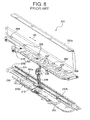
Fig. 5 ] A sectional view along the A-A line inFig. 1 . - [
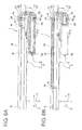
Figs. 6A and 6B ] views for explaining an operation of the electrical wire routing device shown inFig. 1 , whereinFig. 6A is a view showing a state of the slider being positioned at one end of a movement section, andFig. 6B is a view showing a state of the slider being positioned at the other end of movement section. - [
Fig. 7 ] A perspective view showing a conventional electrical wire routing device. - [
Fig. 8 ] An exploded view of the conventional electrical wire routing device shown inFig. 7 . - Hereinafter, an electrical wire routing device according to one embodiment of the present invention will be explained with reference to
Figs. 1 to 6 . - An electrical
wire routing device 1, as shown inFigs. 1 and5 , is an apparatus routing an electric wire from afloor 2 of a passenger compartment as a car body of an automobile to aseat 3 as a slide body slidably disposed in thefloor 2 along the allow Z. Amat 15 is laid on the floor 2 (seeFig. 5 ). The allow Z inFigs. 1 to 6 is parallel to the fore and aft direction of the automobile. The allow X is parallel to the cross direction of the automobile. The allow Y is parallel to the vertical direction of the automobile. - To the
seat 3 are attached electric devices such as a seat sensor detecting whether or not a passenger seats or a seat belt sensor detecting whether or not a passenger seating on theseat 3 uses a seat belt. - The
electric wire 5 is a well-known covered electric wire, and connects the electric devices attached to theseat 3 to an ECU (Electronic Control Unit) attached to thefloor 2, i.e., a car body. - The electrical
wire routing device 1 includes: acase 9 fixed to thefloor 2 and arranged under themat 15, acorrugated tube 4 as a tube accommodating aelectric wire 5, aslider 10 to which oneend 4a of thecorrugated tube 4, i.e., thewire 5 is attached guiding theelectric wire 5 extracted from the oneend 4a into theseat 3 and sliding in acase 9 in association with the movement of theseat 3, aguide member 12 attached to thecase 9, a pair ofmalls 17a and a7b (shown in onlyFig. 5 , omitted in the other Figs.) - The
case 9, as shown inFig. 1 , follows parallel to asupport rail 6 to which asupport body 11 supporting theseat 3 is slidably attached, and includes a movement section 7 to which aslider 10 is slidably attached in the sliding direction, ahousing section 8 tubularly extending along the longitudinal direction of the movement section 7 (the allow Z direction), following parallel to the movement section 7, and accommodating thecorrugated tube 4, i.e., the extra length of theelectric wire 5 extracted from oneend 7a of the movement section 7 with the extra length bent in a U-shape. Namely, thesupport rail 6, the movement section 7 and thehousing section 8 are arranged sequentially in the direction perpendicular to theseat 3 sliding. The move 7 and thehousing section 8 are disposed separately. - The
support body 11, shown inFig. 5 , includes aseat attachment portion 13 attached to theseat 3, and a slidingportion 14 sliding in thesupport rail 6 positioned within thesupport rail 6. - The
support rail 6 is formed by a metal plate being folded back and the like, and includes abottom wall 61 stacked on thefloor 2, a pair of side walls standing from each of the both ends of thebottom wall 61 in the width direction (the allow X direction), a pair ofupper walls 63 extending from the upper end of the eachside wall 62 to the direction of approaching each other and opposite to thebottom wall 61, and a pair ofinner walls 64 extending from an end away from theside walls 62 of the eachupper wall 63 toward thebottom wall 61 side. The pair ofinner walls 64 are spaced each other and spaced from thebottom wall 61. A slit open to theseat 3 is thus formed between the pair of theinner walls 64. Thesupport rail 6 is formed in the rail shape, i.e., the tubelar shape such that the cross section thereof is equal from one end to the other end in the longitudinal direction (the allow Z direction) as shown inFig. 1 . Each of amall Fig. 5 ) is attached to the outer circumference of the pair of theupper walls 63. The pair of themalls support rail 6. - Further, the sliding
portion 14 of thesupport body 11 includes amiddle portion 14a positioned between the pair ofinner walls 64, i.e., the slit, a pair ofextensions 14b communicating with themiddle portion 14a and extending in the direction of separating each other (the allow X direction). The pair ofextensions 14b is each positioned in a pair of spaces away from each other surrounded by thebottom wall 61, theside wall 62,upper wall 63, andinner wall 64 of thesupport rail 6. Further, theseat attachment portion 13 is arranged above themiddle portion 14a, i.e., the outside of therail 6 and projects toward the passenger compartment from acut 15a disposed in the mat 15 (shown in onlyFig. 5 ). - In the embodiment the movement section 7 is formed by a metal plate being folded back and the like and includes, as shown in
Fig. 5 , abottom wall 71 stacked on thefloor 2, aside wall 72 standing from the end near thesupport rail 6 in the width direction (the allow X direction) of thebottom wall 71, anupper wall 73 extending from the upper end of theside wall 72 toward thehousing section 8 side, aninner wall 74 extending from an end away from theside wall 72 of theupper wall 73 toward thebottom wall 71 side, aside wall 75 extending from an end near thehousing section 8 in the width direction of thebottom wall 71, anupper wall 76 extending from an upper end of theside wall 75 toward thehousing section 8 side, and a outer wall 77 extending from an end away from theside wall 75 of theupper wall 76 towardbottom wall 71 side. Further, theinner wall 74 and theside wall 75 are spaced each other. Theinner wall 74 is spaced from thebottom wall 71. A slit 78 open to theseat 3 is formed between theinner wall 74 and theside wall 75. The movement section 7, as shown inFig. 1 , is formed in the rail shape, i.e., the tubelar shape such that cross section thereof is equal from oneend 7a to theend 7b in the longitudinal direction. - In the embodiment the
housing section 8 is made of metal, as sown inFig. 5 , includes abottom wall 80 stacked on thefloor 2, aupper wall 83 opposite to thebottom wall 80, aside wall 82 connecting an end of thebottom wall 80 near the movement section 7 with an end of theupper wall 83 near the movement section 7, and aside wall 81 connecting an end of thebottom wall 80 away from the movement section 7 with an end of theupper wall 83 away from the movement section 7, and is formed in the square tubelar shape such that cross section thereof is equal from oneend 8a to theother end 8b in the longitudinal direction (the allow Z direction). Thehousing section 8 is arranged in the direction parallel to the movement section 7. The oneend 8a in the longitudinal direction of thehousing section 8 adjoins to oneend 7a of the movement section 7. The extra length of thecorrugated tube 4 extracted from the oneend 7a of the movement section 7 is drawn into thehousing section 8 from the oneend 8a. - The
side wall 75 of the movement section 7 and theside wall 82 of thehousing section 8 mentioned above correspond to "the partition wall" recited in claims. - In the present invention, since the extra length of the
corrugated tube 4 is accommodated in thehousing section 8 with the extra length bent in a U-shape, the length of thehousing section 8 can be arranged smaller than when the extra length is accommodated with the extra length straightly stretched. Namely, the electrical wire routing device can be formed compact. - Further, in the present invention, since the movement section 7 and the
housing section 8 are provided as separated parts, the stiffness of the movement section 7 and thehousing section 8 can be improved, which allows the strength of thecase 9 to be improved. The recess or the projection, which would have been provided (seeFigs. 7 and8 ) for improving stiffness heretofore, are not required to be provided in the movement section 7 and thehousing section 8,which allows the shape thereof to be simplified. Further, since each of the movement section 7 and thehousing section 8 is provided as separated parts and formed in the cross-sectional uniform shape along the longitudinal direction, these movement section 7 and thehousing section 8 can be formed by extrusion molding or roll molding at low processing cost. The roll molding denotes a fabrication method that by metal plate in the band plate shape being passed through in sequence a plurality of pairs of molding rolls arranged sequentially, the metal plate is deformed along the surface of the molding rolls so that the metal plate is fabricated in the various shape such as cylindrical or columnar shape. Although, in the present embodiment, the movement section 7 andhousing section 8 are made of metal, the movement section or the housing section also made of synthetic resin, not limited thereby in the present invention. Namely, the movement section and the housing section in the invention may be made of any materials as far as they can withstand deformation or breakage when stomped by the passenger of the automobile. - The above-mentioned
corrugated tube 4 is made of synthetic resin such as polypropylene, formed in the tubenal bellows shape with small-diameter troughs and large-diameter peaks alternately continued along the axial direction, and thus formed bent-deformable, i.e., elastic, deformable. Thecorrugated tube 4 protects theelectric wire 5 by passing through theelectric wire 5 therein. Theelectric wire 5 in the invention may be also single or plural. - The
slider 10 is made of synthetic resin, and includes, as shown inFigs. 4 and5 , atube attachment portion 30 slidably attached to aspace 79 surrounded by thebottom wall 71, theside wall 72, theupper wall 73, and theinner wall 74 of the movement section 7 mentioned above, to which oneend 4a of thecorrugated tube 4 is attached to, and aslider body 40 guiding theelectric wire 5 extracted from oneend 4a of thecorrugated tube 4, from inside the movement section 7 into theseat 3 via theslit 78. The oneend 4a of thecorrugated tube 4 is also extracted from the oneend 8a of thehousing section 8 and drawn from the oneend 7a of the movement section 7 into thespace 79 of the movement section 7. - Furthermore, the
space 79 of the movement section 7 and theslit 78 mentioned above are displaced each other along the width direction of the movement section 7 (the allow X direction). The displacement of thespace 79 and slit 78 each other in the width direction of the movement section 7 in the invention prevents foreign particles penetrating into the movement section 7 through theslit 78 from being clogged in thespace 79 and then theslider 10 from not moving smoothly. In case of foreign particles such as a branch penetrating into the movement section 7, this also prevents the foreign particles from contacting thecorrugated tube 4 and thetube attachment portion 30, and then thecorrugated tube 4 and thetube attachment portion 30 from being damaged. - The
tube attachment portion 30 includes a pair ofclips end 4a of thecorrugated tube 4 and extending along the longitudinal direction of the movement section 7, a hinge coupling the pair ofclamps clamps corrugated tube 4 clipped between the pair ofclamps - The one of the pair of
clamps 31 is stacked on the lower side of the oneend 4a of thecorrugated tube 4. Theclamp 31 has a plurality ofribs 32 biting into troughs, i.e., between peaks of thecorrugated tube 4. - The other of the pair of
clamps 34 is stacked on the upper side of the oneend 4a of thecorrugated tube 4. Theclamp 34 has a plurality ofribs 35 biting into troughs, i.e., between peaks of thecorrugated tube 4. - Further, the
corrugated tube 4 is clipped between the pair ofclips ribs corrugated tube 4 from deflecting from the pair ofclips - The
slider body 40 includes afirst tube portion 42 tubelarly extending from theclip 31 along the width direction of the movement section 7, atube 41 tubelarly formed in a L-shape by asecond tube portion 43 tubelarly extending upward from an end away from theclip 31 of thefirst tube portion 42, and aguide section 45 extending in the plate-like shape from the upper end of thesecond tube portion 43. Thesecond tube portion 43 is passed through theslit 78, and the upside thereof is positioned out the movement section 7 as shown inFig. 5 . By theelectric wire 5 extracted from the oneend 4a of thecorrugated tube 4 and passed through between the pair ofclips tube 41, thetube 4 guides theelectric wire 5 passing from within the movement section 7 through theslit 78 to theseat 3. Thetube portion 41 is also provided with aslit 44 straightly cut from the end of theclip 31 side of thefirst tube portion 42 to the top of thesecond tube portion 43. Theguide section 45 also follows theelectric wire 5 extracted from thetube portion 41 as shown inFig. 4 , and guides theelectric wire 5 to theseat 3. - Namely, the
slider 40 has theelectric wire 5 pass through thetube portion 41, and the upside thereof is passed through theslit 78 of the movement section 7 and acut 15b of the mat 15 (only shown inFig. 5 ), projects toward the passenger compartment, and guides theelectric wire 5 to theseat 3 positioned in the passenger compartment side. - The
slider 10 in the embodiment is fastened to theseat 3 with a string or a wire of metal, synthetic resin, or cloth. Theslider 10 thus slides in association with the movement of theseat 3. The length of the string or the wire is also formed shorter than that of theelectric wire 5 wired between theslider 10 and theseat 3. Besides above, in the invention, theslider 10 may be fastened to thesupport body 11 with such a string or a wire as mentioned above. Note that because theslider 10 is fastened to theseat 3 with the electric 5, theslider 10 may not be fastened to theseat 3 or thesupport body 11 with a string or a wire. - The
guide member 12 is made of synthetic resin, and as shown inFigs. 2 and6 , includes amain body 21 formed in the generally half-columnar shape, aplate portion 20 attached to the upper surface of themain body 21. Themain body 21 includes a first fixingportion 24 fixed to the oneend 7a of the movement section 7, asecond fixing portion 25 attached to the oneend 8a of thehousing section 8, and aguide section 22 bending thecorrugated tube 4 extracted from the oneend 7a of the movement section 7 to guide it into the oneend 8a of thehousing section 8 positioned near the oneend 7a of the movement section 7 and guiding thecorrugated tube 4 to abut theinner surface 81a of thehousing section 8 away from the movement section 7, i.e., the inner surface of theside wall 81. - The
guide section 22 is a slit convexly formed from the upper surface of themain body 21, and is formed such that the planer view thereof is semicircular or in a U-shape. Thecorrugated tube 4 is bent in a U-shape by being accommodated in theguide section 22, and is guided into thehousing section 8. The bottom of theguide section 22 is arranged inclined in the direction away from thefloor 2 as approaching the movement section 7 from thehousing section 8, and a portion of the bottom of theguide section 22 near the movement section 7 is spaced from thefloor 2. - The
corrugated tube 4 drawn into the oneend 8a of thehousing section 8 by theguide section 22 is further bent in a U-shape in thehousing section 8 and the bent portion thereof abuts theinner surface 82a of thehousing section 8 near the movement section 7, i.e., the inner surface of theside wall 82 by the force of restitution of thecorrugated tube 4. Namely, thecorrugated tube 4 is enlarged in thehousing section 4 by force of restitution generated by being bent twice in the same bending direction to push against theinner surface 81a and theinner surface 82a. - Furthermore, the
guide member 12 is provide with aderivation section 23 in themain body 21 extracting theelectric wire 5 out of thehousing section 8, which has been extracted from theother end 4b of thecorrugated tube 4 bent again in thehousing section 8, in such a way as to cross each other at height vertically different from theguide section 22. Thederivation section 23 is composed of ahole 23a communicating with the oneend 8a of thehousing section 8 and a space positioned under a portion of the bottom of theguide section 22 near the movement section 7, and a pair ofstands guide section 22 near the movement section 7 toward thefloor 2 side. Theother end 4b of thecorrugated tube 4 bent again in thehousing section 8 is positioned at the oneend 8a of thehousing section 8, and theelectric wire 5 extracted from the oneend 8a is passed through thehole 23a mentioned above, then through between the pair ofstands guide section 22, and extracted out of thehousing section 8. Further, theelectric wire 5 thus extracted out of thehousing section 8 is connected to electric devices such as an ECU (Electronic Control Unit) attached to the car body as mentioned above. - Since the present invention includes: the
guide member 12 having theguide section 22 bending thecorrugated tube 4 in a U-shape extracted from the movement section 7, guiding thecorrugated tube 4 into thehousing section 8, and guiding thecorrugated tube 4 abutting to theinner surface 81a of thehousing section 8 away from the movement section 7; and thecorrugated tube 4 bent again in a U-shape in the same bent direction as bent by theguide section 22 in thehousing section 8, thecorrugated tube 4 is enlarged in thehousing section 8 to push against theinner surface 81a, 81b, and therefore thecorrugate tube 4 is not rubbed to each other when thecorrugated tube 4 come in and out thehousing section 8 without providing the regulation portion (seeFig. 8 ) or a guide member such as a pulley which would conventionally have been provided so that thecorrugated tube 4 moves smoothly, which further prevents thecorrugated tube 4 positioned outside thecase 9 from scarring. Accordingly, thehousing section 8 can be simply, tubularly formed and simply configured; and compact electrical wire routing device can be provided. Note that in the present invention "the same bending direction" means a plurality of bending portions bending spiral wholly. - Further, since the
corrugated tube 4 extracted from thespace 79 of the movement section 7 is guided to abut theinner surface 81a of thehousing section 8 away from the movement section 7, the routing root of thecorrugated tube 4 is largely turned, i.e., the bending radius becomes large, which allows thecorrugate tube 4 to move smoothly and prevents thecorrugated tube 4 from having heavy bent habit. Further, bent of thecorrugated tube 4 in a U-shape in thehousing section 8 in the same bent direction as bent by theguide section 22 prevents thecorrugated tube 4 from having heavy bent habit in an S-shape. - Since there is provided the
guide member 12 in the present invention having thederivation section 23 extracting theelectric wire 5 extracted from theother end 4b of thecorrugated tube 4 bent again in thehousing section 8 out of thehousing section 8 in such a way as to cross to each other at height vertically different from theguide section 22, it prevents thecorrugated tube 4 andelectric wire 5 from rubbing to each other at the crossed portions when thecorrugated tube 4 comes in and out thehousing section 8. Alternatively, in the invention, thecorrugated tube 4 is further extended from theother end 4b, and the extended portion can be passed through thederivation section 23. - The pair of
malls upper walls malls slit 78, and therefore prevents foreign particles such as grit and dust from penetrating from theslit 78 into the movement section 7. - Next, operation of the electrical wire routing device configured as mentioned above is described in reference to the
Fig. 6 . In the electricalwire routing device 1, as shown inFig. 6(a) , the corrugated tube, i.e., the extra length of theelectric wire 5 is accommodated in thehousing section 8 when theslider 10, i.e., theseat 3 is positioned at the oneend 7a of the movement section 7. Then, as shown inFig. 6(b) , as theslider 10, i.e., theseat 3 is sliding from the oneend 7a of the movement section 7 to theother end 7b thereof, thecorrugated tube 4, i.e., the extra length of theelectric wire 5 is been extracted from the oneend 8a of thehousing section 8 and drawn into the oneend 7a of the movement section 7. - In the embodiment mentioned above, though the movement section 7 and the
housing section 8 are provided as separated parts, in the present invention, those can alternatively be disposed integrally. - In the embodiment mentioned above, though "a tube" is a corrugated tube, in the present invention, "a tube" can alternatively be a tube having force of restitution which will return straightly when given bending force.
- Since the embodiment mentioned above only indicates a typical configuration of the present invention, the invention may not be limited to these embodiments. Therefore, unless otherwise such changes and modifications depart from the scope of the present invention hereafter defied, they should be construed as being included therein.
-
- 1
- electrical wire routing device
- 2
- floor (car body)
- 3
- seat (slide body)
- 4
- corrugated tube (tube)
- 5
- electric wire
- 7
- movement section
- 8
- housing section
- 9
- case
- 10
- slider
- 12
- guide member
- 22
- guide section
- 23
- derivation section
- 75, 82
- side wall (partition wall)
- 81a, 82a
- inner surface
Claims (5)
- An electrical wire routing device for routing an electric wire across between a car body and a slide body disposed slidably with respect to the car body, comprising:a case including a movement section, to which a slider is slidably attached along a sliding direction of the slide body, and a housing section accommodating an extra length of the electric wire, wherein the electric wire is attached to the slider is guided into the slide body, wherein the movement section and the housing section are placed in the direction perpendicular to the sliding direction and fixed to the car body, and wherein the case is fixed to the car body; anda partition wall separating the movement section and the housing section and being disposed between the movement section and the housing section along a whole length of the movement and the housing;wherein the electric wire is extracted from one end portion of the movement section and drawn into the housing section through one end portion of the housing section, wherein the end portion is positioned near the one end portion of the movement section, and wherein the extra length of the electric wire is accommodated in the housing section while being bent in a U-shape.
- The electrical wire routing device as claimed in claim 1, further comprising:a tube made of elastic and deformable material, the tube accommodating the electric wire; anda guide member provided with a guide section, the guide section bending the tube extracted from the one of the movement section in a U-shape so as to guide the tube into the one end of the housing section, and guiding the tube so as to abut a inner side surface of the housing section away from the movement section,wherein the tube is bent in a U-shape in the housing section, and wherein a portion following the U-shape abuts the inner side surface of the housing section near the movement section by force of elastic restitution of the tube.
- The electrical wire routing device as claimed in claim 2, further comprising a derivation section disposed in the guide member, the derivation section crossing the electric wire extracted from the tube bent in the housing section and the guide section at vertically different height for extracting the electric wire out of the housing section.
- The electrical wire routing device as claimed in any one of claims 1 to 3, wherein the movement section and the housing section are provided as separated parts, and wherein each of the movement section and housing section includes a side wall as the partition wall.
- The electrical wire routing device as claimed in claim 4, wherein each of the movement section and the housing section is formed in a uniform cross-sectional shape along the sliding direction.
Applications Claiming Priority (2)
| Application Number | Priority Date | Filing Date | Title |
|---|---|---|---|
| JP2009034358A JP5378826B2 (en) | 2009-02-17 | 2009-02-17 | Electric wire routing device |
| PCT/JP2009/069968 WO2010095326A1 (en) | 2009-02-17 | 2009-11-26 | Electrical wire routing device |
Publications (3)
| Publication Number | Publication Date |
|---|---|
| EP2400615A1 true EP2400615A1 (en) | 2011-12-28 |
| EP2400615A4 EP2400615A4 (en) | 2013-09-18 |
| EP2400615B1 EP2400615B1 (en) | 2014-09-24 |
Family
ID=42633619
Family Applications (1)
| Application Number | Title | Priority Date | Filing Date |
|---|---|---|---|
| EP09840429.6A Active EP2400615B1 (en) | 2009-02-17 | 2009-11-26 | Electrical wire routing device |
Country Status (4)
| Country | Link |
|---|---|
| US (1) | US8686286B2 (en) |
| EP (1) | EP2400615B1 (en) |
| JP (1) | JP5378826B2 (en) |
| WO (1) | WO2010095326A1 (en) |
Families Citing this family (26)
| Publication number | Priority date | Publication date | Assignee | Title |
|---|---|---|---|---|
| US20110292213A1 (en) * | 2010-05-26 | 2011-12-01 | Lacey James H | Door mountable camera surveillance device and method |
| JP5608516B2 (en) * | 2010-11-10 | 2014-10-15 | 矢崎総業株式会社 | Harness wiring device |
| JP5800608B2 (en) * | 2011-02-23 | 2015-10-28 | 矢崎総業株式会社 | Harness wiring device |
| JP5915287B2 (en) * | 2012-03-15 | 2016-05-11 | 住友電装株式会社 | Wire harness wiring structure for slide sheet |
| JP5962495B2 (en) * | 2012-12-20 | 2016-08-03 | 住友電装株式会社 | Wire harness wiring device for slide sheet |
| JP5974972B2 (en) * | 2012-12-20 | 2016-08-23 | 住友電装株式会社 | Wire harness wiring device for slide sheet |
| JP6054198B2 (en) | 2013-02-19 | 2016-12-27 | 矢崎総業株式会社 | Slide feeder |
| JP6015506B2 (en) * | 2013-03-15 | 2016-10-26 | 住友電装株式会社 | Wire harness wiring device for slide sheet |
| JP5939181B2 (en) * | 2013-03-15 | 2016-06-22 | 住友電装株式会社 | Wire harness wiring device for slide sheet |
| JP5892096B2 (en) * | 2013-03-22 | 2016-03-23 | 住友電装株式会社 | Slider |
| JP5979052B2 (en) * | 2013-03-22 | 2016-08-24 | 住友電装株式会社 | Wire harness wiring device for slide sheet |
| JP6015512B2 (en) * | 2013-03-22 | 2016-10-26 | 住友電装株式会社 | Wire harness wiring device for slide sheet |
| JP6011415B2 (en) * | 2013-03-26 | 2016-10-19 | 住友電装株式会社 | Wire harness wiring device for slide sheet |
| JP5939200B2 (en) * | 2013-05-29 | 2016-06-22 | 住友電装株式会社 | Connecting structure of slide sheet and slider |
| JP6052064B2 (en) * | 2013-05-30 | 2016-12-27 | 住友電装株式会社 | Wire harness wiring structure for slide sheet |
| JP2016131423A (en) | 2015-01-13 | 2016-07-21 | 株式会社オートネットワーク技術研究所 | Wire protection member, wire harness with wire protection member, and slide wiring device |
| US9810347B1 (en) * | 2015-09-30 | 2017-11-07 | The United States Of America As Represented By The Secretary Of The Navy | Torpedo power cable attachment hardware |
| JP2018085876A (en) * | 2016-11-25 | 2018-05-31 | 矢崎総業株式会社 | Fixing structure for power supply device |
| JP6564813B2 (en) * | 2017-05-30 | 2019-08-21 | 矢崎総業株式会社 | Protective case for electric wire |
| JP6772997B2 (en) * | 2017-09-29 | 2020-10-21 | 株式会社オートネットワーク技術研究所 | Wire harness routing device |
| JP6645487B2 (en) | 2017-10-30 | 2020-02-14 | セイコーエプソン株式会社 | Printed circuit board |
| US10522990B1 (en) * | 2018-08-29 | 2019-12-31 | The Boeing Company | System and method for an under floor seat-to-seat wiring trough to facilitate flat floors in aircraft passenger cabin |
| CN109552209B (en) * | 2019-01-02 | 2020-05-05 | 延锋安道拓座椅有限公司 | Rapid assembling and protecting mechanism for wiring harness in sliding rail |
| CN109572498B (en) * | 2019-01-02 | 2020-09-22 | 延锋安道拓座椅有限公司 | Power supply mechanism of long-stroke seat |
| US11505321B2 (en) | 2020-06-15 | 2022-11-22 | The Boeing Company | Underfloor wire routing system for passenger cabin |
| JP7269209B2 (en) * | 2020-11-16 | 2023-05-08 | 矢崎総業株式会社 | Corrugated tube mounting structure |
Citations (2)
| Publication number | Priority date | Publication date | Assignee | Title |
|---|---|---|---|---|
| US20060060370A1 (en) * | 2004-07-23 | 2006-03-23 | Yazaki Corporation | Slide wiring apparatus |
| US20060199416A1 (en) * | 2005-03-03 | 2006-09-07 | Yazaki Corporation | Power-supply device |
Family Cites Families (6)
| Publication number | Priority date | Publication date | Assignee | Title |
|---|---|---|---|---|
| JP3503870B2 (en) * | 1998-03-18 | 2004-03-08 | 矢崎総業株式会社 | Routing structure of vehicle door harness |
| DE102004013974B4 (en) * | 2004-03-19 | 2007-01-04 | Igus Gmbh | sliding door system |
| JP4667844B2 (en) * | 2004-05-31 | 2011-04-13 | 古河電気工業株式会社 | Power supply device for sliding door |
| JP2007143238A (en) * | 2005-11-16 | 2007-06-07 | Yazaki Corp | Harness wiring structure, and power feeding apparatus equipped therewith |
| JP5074757B2 (en) * | 2006-12-19 | 2012-11-14 | 矢崎総業株式会社 | Power feeding device and harness wiring structure using the same |
| US8841551B2 (en) * | 2009-02-17 | 2014-09-23 | Yazaki Corporation | Sliding device for a cable management device |
-
2009
- 2009-02-17 JP JP2009034358A patent/JP5378826B2/en active Active
- 2009-11-26 WO PCT/JP2009/069968 patent/WO2010095326A1/en active Application Filing
- 2009-11-26 EP EP09840429.6A patent/EP2400615B1/en active Active
- 2009-11-26 US US13/201,418 patent/US8686286B2/en active Active
Patent Citations (2)
| Publication number | Priority date | Publication date | Assignee | Title |
|---|---|---|---|---|
| US20060060370A1 (en) * | 2004-07-23 | 2006-03-23 | Yazaki Corporation | Slide wiring apparatus |
| US20060199416A1 (en) * | 2005-03-03 | 2006-09-07 | Yazaki Corporation | Power-supply device |
Non-Patent Citations (1)
| Title |
|---|
| See also references of WO2010095326A1 * |
Also Published As
| Publication number | Publication date |
|---|---|
| JP5378826B2 (en) | 2013-12-25 |
| EP2400615B1 (en) | 2014-09-24 |
| WO2010095326A1 (en) | 2010-08-26 |
| US20120024561A1 (en) | 2012-02-02 |
| JP2010193599A (en) | 2010-09-02 |
| US8686286B2 (en) | 2014-04-01 |
| EP2400615A4 (en) | 2013-09-18 |
Similar Documents
| Publication | Publication Date | Title |
|---|---|---|
| EP2400615B1 (en) | Electrical wire routing device | |
| US9308833B2 (en) | Harness wiring apparatus | |
| EP2476589B1 (en) | Wire harness routing device | |
| JP5550631B2 (en) | Slide device | |
| JP5180157B2 (en) | Rail device and wire harness routing device having the rail device | |
| JP5522996B2 (en) | Wire harness wiring device | |
| JP2016131423A (en) | Wire protection member, wire harness with wire protection member, and slide wiring device | |
| JP2011025743A (en) | Wire harness routing device | |
| JP5275467B2 (en) | Wire harness wiring device | |
| JP5627752B2 (en) | Electric wire routing device | |
| JP5286063B2 (en) | Slide device | |
| JP5800608B2 (en) | Harness wiring device | |
| JP5888248B2 (en) | Electric wire exterior parts, wire harnesses and slide wiring devices | |
| JP5384851B2 (en) | Decorative member mounting structure, and electric wire routing device having the decorative member mounting structure | |
| JP5086170B2 (en) | Electric wire routing device | |
| JP2012105446A (en) | Harness routing device | |
| JP5191793B2 (en) | Electric wire routing device | |
| JP5134429B2 (en) | Electric wire routing device | |
| JP2009071895A (en) | Wire harness routing device | |
| JP2009273313A (en) | Wire organizer |
Legal Events
| Date | Code | Title | Description |
|---|---|---|---|
| PUAI | Public reference made under article 153(3) epc to a published international application that has entered the european phase |
Free format text: ORIGINAL CODE: 0009012 |
|
| 17P | Request for examination filed |
Effective date: 20110803 |
|
| AK | Designated contracting states |
Kind code of ref document: A1 Designated state(s): AT BE BG CH CY CZ DE DK EE ES FI FR GB GR HR HU IE IS IT LI LT LU LV MC MK MT NL NO PL PT RO SE SI SK SM TR |
|
| DAX | Request for extension of the european patent (deleted) | ||
| A4 | Supplementary search report drawn up and despatched |
Effective date: 20130820 |
|
| RIC1 | Information provided on ipc code assigned before grant |
Ipc: H02G 11/00 20060101AFI20130813BHEP Ipc: B60R 16/02 20060101ALI20130813BHEP |
|
| GRAP | Despatch of communication of intention to grant a patent |
Free format text: ORIGINAL CODE: EPIDOSNIGR1 |
|
| INTG | Intention to grant announced |
Effective date: 20140409 |
|
| GRAS | Grant fee paid |
Free format text: ORIGINAL CODE: EPIDOSNIGR3 |
|
| GRAA | (expected) grant |
Free format text: ORIGINAL CODE: 0009210 |
|
| AK | Designated contracting states |
Kind code of ref document: B1 Designated state(s): AT BE BG CH CY CZ DE DK EE ES FI FR GB GR HR HU IE IS IT LI LT LU LV MC MK MT NL NO PL PT RO SE SI SK SM TR |
|
| REG | Reference to a national code |
Ref country code: GB Ref legal event code: FG4D |
|
| REG | Reference to a national code |
Ref country code: CH Ref legal event code: EP |
|
| REG | Reference to a national code |
Ref country code: AT Ref legal event code: REF Ref document number: 688976 Country of ref document: AT Kind code of ref document: T Effective date: 20141015 |
|
| REG | Reference to a national code |
Ref country code: IE Ref legal event code: FG4D |
|
| REG | Reference to a national code |
Ref country code: DE Ref legal event code: R096 Ref document number: 602009026882 Country of ref document: DE Effective date: 20141106 |
|
| PG25 | Lapsed in a contracting state [announced via postgrant information from national office to epo] |
Ref country code: SE Free format text: LAPSE BECAUSE OF FAILURE TO SUBMIT A TRANSLATION OF THE DESCRIPTION OR TO PAY THE FEE WITHIN THE PRESCRIBED TIME-LIMIT Effective date: 20140924 Ref country code: NO Free format text: LAPSE BECAUSE OF FAILURE TO SUBMIT A TRANSLATION OF THE DESCRIPTION OR TO PAY THE FEE WITHIN THE PRESCRIBED TIME-LIMIT Effective date: 20141224 Ref country code: GR Free format text: LAPSE BECAUSE OF FAILURE TO SUBMIT A TRANSLATION OF THE DESCRIPTION OR TO PAY THE FEE WITHIN THE PRESCRIBED TIME-LIMIT Effective date: 20141225 Ref country code: LT Free format text: LAPSE BECAUSE OF FAILURE TO SUBMIT A TRANSLATION OF THE DESCRIPTION OR TO PAY THE FEE WITHIN THE PRESCRIBED TIME-LIMIT Effective date: 20140924 Ref country code: FI Free format text: LAPSE BECAUSE OF FAILURE TO SUBMIT A TRANSLATION OF THE DESCRIPTION OR TO PAY THE FEE WITHIN THE PRESCRIBED TIME-LIMIT Effective date: 20140924 |
|
| REG | Reference to a national code |
Ref country code: LT Ref legal event code: MG4D Ref country code: NL Ref legal event code: VDEP Effective date: 20140924 |
|
| PG25 | Lapsed in a contracting state [announced via postgrant information from national office to epo] |
Ref country code: LV Free format text: LAPSE BECAUSE OF FAILURE TO SUBMIT A TRANSLATION OF THE DESCRIPTION OR TO PAY THE FEE WITHIN THE PRESCRIBED TIME-LIMIT Effective date: 20140924 Ref country code: HR Free format text: LAPSE BECAUSE OF FAILURE TO SUBMIT A TRANSLATION OF THE DESCRIPTION OR TO PAY THE FEE WITHIN THE PRESCRIBED TIME-LIMIT Effective date: 20140924 Ref country code: CY Free format text: LAPSE BECAUSE OF FAILURE TO SUBMIT A TRANSLATION OF THE DESCRIPTION OR TO PAY THE FEE WITHIN THE PRESCRIBED TIME-LIMIT Effective date: 20140924 |
|
| REG | Reference to a national code |
Ref country code: AT Ref legal event code: MK05 Ref document number: 688976 Country of ref document: AT Kind code of ref document: T Effective date: 20140924 |
|
| PG25 | Lapsed in a contracting state [announced via postgrant information from national office to epo] |
Ref country code: NL Free format text: LAPSE BECAUSE OF FAILURE TO SUBMIT A TRANSLATION OF THE DESCRIPTION OR TO PAY THE FEE WITHIN THE PRESCRIBED TIME-LIMIT Effective date: 20140924 |
|
| PG25 | Lapsed in a contracting state [announced via postgrant information from national office to epo] |
Ref country code: PT Free format text: LAPSE BECAUSE OF FAILURE TO SUBMIT A TRANSLATION OF THE DESCRIPTION OR TO PAY THE FEE WITHIN THE PRESCRIBED TIME-LIMIT Effective date: 20150126 Ref country code: SK Free format text: LAPSE BECAUSE OF FAILURE TO SUBMIT A TRANSLATION OF THE DESCRIPTION OR TO PAY THE FEE WITHIN THE PRESCRIBED TIME-LIMIT Effective date: 20140924 Ref country code: ES Free format text: LAPSE BECAUSE OF FAILURE TO SUBMIT A TRANSLATION OF THE DESCRIPTION OR TO PAY THE FEE WITHIN THE PRESCRIBED TIME-LIMIT Effective date: 20140924 Ref country code: IS Free format text: LAPSE BECAUSE OF FAILURE TO SUBMIT A TRANSLATION OF THE DESCRIPTION OR TO PAY THE FEE WITHIN THE PRESCRIBED TIME-LIMIT Effective date: 20150124 Ref country code: CZ Free format text: LAPSE BECAUSE OF FAILURE TO SUBMIT A TRANSLATION OF THE DESCRIPTION OR TO PAY THE FEE WITHIN THE PRESCRIBED TIME-LIMIT Effective date: 20140924 Ref country code: RO Free format text: LAPSE BECAUSE OF FAILURE TO SUBMIT A TRANSLATION OF THE DESCRIPTION OR TO PAY THE FEE WITHIN THE PRESCRIBED TIME-LIMIT Effective date: 20140924 Ref country code: EE Free format text: LAPSE BECAUSE OF FAILURE TO SUBMIT A TRANSLATION OF THE DESCRIPTION OR TO PAY THE FEE WITHIN THE PRESCRIBED TIME-LIMIT Effective date: 20140924 |
|
| PG25 | Lapsed in a contracting state [announced via postgrant information from national office to epo] |
Ref country code: AT Free format text: LAPSE BECAUSE OF FAILURE TO SUBMIT A TRANSLATION OF THE DESCRIPTION OR TO PAY THE FEE WITHIN THE PRESCRIBED TIME-LIMIT Effective date: 20140924 Ref country code: PL Free format text: LAPSE BECAUSE OF FAILURE TO SUBMIT A TRANSLATION OF THE DESCRIPTION OR TO PAY THE FEE WITHIN THE PRESCRIBED TIME-LIMIT Effective date: 20140924 |
|
| REG | Reference to a national code |
Ref country code: DE Ref legal event code: R097 Ref document number: 602009026882 Country of ref document: DE |
|
| PG25 | Lapsed in a contracting state [announced via postgrant information from national office to epo] |
Ref country code: LU Free format text: LAPSE BECAUSE OF FAILURE TO SUBMIT A TRANSLATION OF THE DESCRIPTION OR TO PAY THE FEE WITHIN THE PRESCRIBED TIME-LIMIT Effective date: 20141126 Ref country code: BE Free format text: LAPSE BECAUSE OF NON-PAYMENT OF DUE FEES Effective date: 20141130 Ref country code: MC Free format text: LAPSE BECAUSE OF FAILURE TO SUBMIT A TRANSLATION OF THE DESCRIPTION OR TO PAY THE FEE WITHIN THE PRESCRIBED TIME-LIMIT Effective date: 20140924 |
|
| REG | Reference to a national code |
Ref country code: CH Ref legal event code: PL |
|
| PG25 | Lapsed in a contracting state [announced via postgrant information from national office to epo] |
Ref country code: LI Free format text: LAPSE BECAUSE OF NON-PAYMENT OF DUE FEES Effective date: 20141130 Ref country code: CH Free format text: LAPSE BECAUSE OF NON-PAYMENT OF DUE FEES Effective date: 20141130 Ref country code: DK Free format text: LAPSE BECAUSE OF FAILURE TO SUBMIT A TRANSLATION OF THE DESCRIPTION OR TO PAY THE FEE WITHIN THE PRESCRIBED TIME-LIMIT Effective date: 20140924 |
|
| PLBE | No opposition filed within time limit |
Free format text: ORIGINAL CODE: 0009261 |
|
| STAA | Information on the status of an ep patent application or granted ep patent |
Free format text: STATUS: NO OPPOSITION FILED WITHIN TIME LIMIT |
|
| REG | Reference to a national code |
Ref country code: IE Ref legal event code: MM4A |
|
| 26N | No opposition filed |
Effective date: 20150625 |
|
| REG | Reference to a national code |
Ref country code: FR Ref legal event code: PLFP Year of fee payment: 7 |
|
| PG25 | Lapsed in a contracting state [announced via postgrant information from national office to epo] |
Ref country code: IE Free format text: LAPSE BECAUSE OF NON-PAYMENT OF DUE FEES Effective date: 20141126 |
|
| PG25 | Lapsed in a contracting state [announced via postgrant information from national office to epo] |
Ref country code: SI Free format text: LAPSE BECAUSE OF FAILURE TO SUBMIT A TRANSLATION OF THE DESCRIPTION OR TO PAY THE FEE WITHIN THE PRESCRIBED TIME-LIMIT Effective date: 20140924 |
|
| PG25 | Lapsed in a contracting state [announced via postgrant information from national office to epo] |
Ref country code: SM Free format text: LAPSE BECAUSE OF FAILURE TO SUBMIT A TRANSLATION OF THE DESCRIPTION OR TO PAY THE FEE WITHIN THE PRESCRIBED TIME-LIMIT Effective date: 20140924 |
|
| PG25 | Lapsed in a contracting state [announced via postgrant information from national office to epo] |
Ref country code: BG Free format text: LAPSE BECAUSE OF FAILURE TO SUBMIT A TRANSLATION OF THE DESCRIPTION OR TO PAY THE FEE WITHIN THE PRESCRIBED TIME-LIMIT Effective date: 20140924 |
|
| PG25 | Lapsed in a contracting state [announced via postgrant information from national office to epo] |
Ref country code: HU Free format text: LAPSE BECAUSE OF FAILURE TO SUBMIT A TRANSLATION OF THE DESCRIPTION OR TO PAY THE FEE WITHIN THE PRESCRIBED TIME-LIMIT; INVALID AB INITIO Effective date: 20091126 Ref country code: MT Free format text: LAPSE BECAUSE OF FAILURE TO SUBMIT A TRANSLATION OF THE DESCRIPTION OR TO PAY THE FEE WITHIN THE PRESCRIBED TIME-LIMIT Effective date: 20140924 Ref country code: TR Free format text: LAPSE BECAUSE OF FAILURE TO SUBMIT A TRANSLATION OF THE DESCRIPTION OR TO PAY THE FEE WITHIN THE PRESCRIBED TIME-LIMIT Effective date: 20140924 |
|
| REG | Reference to a national code |
Ref country code: FR Ref legal event code: PLFP Year of fee payment: 8 |
|
| REG | Reference to a national code |
Ref country code: FR Ref legal event code: PLFP Year of fee payment: 9 |
|
| PG25 | Lapsed in a contracting state [announced via postgrant information from national office to epo] |
Ref country code: MK Free format text: LAPSE BECAUSE OF FAILURE TO SUBMIT A TRANSLATION OF THE DESCRIPTION OR TO PAY THE FEE WITHIN THE PRESCRIBED TIME-LIMIT Effective date: 20140924 |
|
| REG | Reference to a national code |
Ref country code: FR Ref legal event code: PLFP Year of fee payment: 10 |
|
| PGFP | Annual fee paid to national office [announced via postgrant information from national office to epo] |
Ref country code: FR Payment date: 20230929 Year of fee payment: 15 |
|
| PGFP | Annual fee paid to national office [announced via postgrant information from national office to epo] |
Ref country code: GB Payment date: 20231006 Year of fee payment: 15 |
|
| PGFP | Annual fee paid to national office [announced via postgrant information from national office to epo] |
Ref country code: IT Payment date: 20231010 Year of fee payment: 15 Ref country code: DE Payment date: 20230929 Year of fee payment: 15 |