EP2400521A1 - Image display apparatus and rib formation method - Google Patents
Image display apparatus and rib formation method Download PDFInfo
- Publication number
- EP2400521A1 EP2400521A1 EP11159136A EP11159136A EP2400521A1 EP 2400521 A1 EP2400521 A1 EP 2400521A1 EP 11159136 A EP11159136 A EP 11159136A EP 11159136 A EP11159136 A EP 11159136A EP 2400521 A1 EP2400521 A1 EP 2400521A1
- Authority
- EP
- European Patent Office
- Prior art keywords
- ribs
- exposure
- wide
- portions
- light emitting
- Prior art date
- Legal status (The legal status is an assumption and is not a legal conclusion. Google has not performed a legal analysis and makes no representation as to the accuracy of the status listed.)
- Withdrawn
Links
- 238000000034 method Methods 0.000 title claims description 26
- 230000015572 biosynthetic process Effects 0.000 title description 4
- 125000006850 spacer group Chemical group 0.000 claims abstract description 77
- 239000000758 substrate Substances 0.000 claims abstract description 34
- 239000011521 glass Substances 0.000 claims description 15
- 239000011347 resin Substances 0.000 claims description 15
- 229920005989 resin Polymers 0.000 claims description 15
- 239000011159 matrix material Substances 0.000 claims description 8
- 238000000016 photochemical curing Methods 0.000 claims description 2
- OAICVXFJPJFONN-UHFFFAOYSA-N Phosphorus Chemical compound [P] OAICVXFJPJFONN-UHFFFAOYSA-N 0.000 description 17
- 230000001965 increasing effect Effects 0.000 description 9
- 238000011161 development Methods 0.000 description 6
- 230000000052 comparative effect Effects 0.000 description 4
- 238000004132 cross linking Methods 0.000 description 3
- CDBYLPFSWZWCQE-UHFFFAOYSA-L Sodium Carbonate Chemical compound [Na+].[Na+].[O-]C([O-])=O CDBYLPFSWZWCQE-UHFFFAOYSA-L 0.000 description 2
- 238000005452 bending Methods 0.000 description 2
- 239000005388 borosilicate glass Substances 0.000 description 2
- 239000011248 coating agent Substances 0.000 description 2
- 238000000576 coating method Methods 0.000 description 2
- 238000013461 design Methods 0.000 description 2
- 230000009477 glass transition Effects 0.000 description 2
- 238000005259 measurement Methods 0.000 description 2
- 239000003566 sealing material Substances 0.000 description 2
- 230000015556 catabolic process Effects 0.000 description 1
- 230000007423 decrease Effects 0.000 description 1
- 238000006731 degradation reaction Methods 0.000 description 1
- 238000010894 electron beam technology Methods 0.000 description 1
- 238000001803 electron scattering Methods 0.000 description 1
- 238000010828 elution Methods 0.000 description 1
- 230000002708 enhancing effect Effects 0.000 description 1
- 238000010438 heat treatment Methods 0.000 description 1
- 239000003999 initiator Substances 0.000 description 1
- 239000007788 liquid Substances 0.000 description 1
- 238000004519 manufacturing process Methods 0.000 description 1
- 239000000463 material Substances 0.000 description 1
- 229910052751 metal Inorganic materials 0.000 description 1
- 239000002184 metal Substances 0.000 description 1
- 238000012986 modification Methods 0.000 description 1
- 230000004048 modification Effects 0.000 description 1
- 230000002093 peripheral effect Effects 0.000 description 1
- 239000000843 powder Substances 0.000 description 1
- 238000007650 screen-printing Methods 0.000 description 1
- 239000005361 soda-lime glass Substances 0.000 description 1
- 229910000029 sodium carbonate Inorganic materials 0.000 description 1
- 239000007787 solid Substances 0.000 description 1
- 239000002904 solvent Substances 0.000 description 1
- 239000000126 substance Substances 0.000 description 1
- 238000012360 testing method Methods 0.000 description 1
- 238000013519 translation Methods 0.000 description 1
- XLYOFNOQVPJJNP-UHFFFAOYSA-N water Substances O XLYOFNOQVPJJNP-UHFFFAOYSA-N 0.000 description 1
Images


Classifications
-
- H—ELECTRICITY
- H01—ELECTRIC ELEMENTS
- H01J—ELECTRIC DISCHARGE TUBES OR DISCHARGE LAMPS
- H01J29/00—Details of cathode-ray tubes or of electron-beam tubes of the types covered by group H01J31/00
- H01J29/02—Electrodes; Screens; Mounting, supporting, spacing or insulating thereof
- H01J29/10—Screens on or from which an image or pattern is formed, picked up, converted or stored
- H01J29/18—Luminescent screens
- H01J29/30—Luminescent screens with luminescent material discontinuously arranged, e.g. in dots, in lines
- H01J29/32—Luminescent screens with luminescent material discontinuously arranged, e.g. in dots, in lines with adjacent dots or lines of different luminescent material, e.g. for colour television
- H01J29/325—Luminescent screens with luminescent material discontinuously arranged, e.g. in dots, in lines with adjacent dots or lines of different luminescent material, e.g. for colour television with adjacent lines
-
- H—ELECTRICITY
- H01—ELECTRIC ELEMENTS
- H01J—ELECTRIC DISCHARGE TUBES OR DISCHARGE LAMPS
- H01J29/00—Details of cathode-ray tubes or of electron-beam tubes of the types covered by group H01J31/00
- H01J29/02—Electrodes; Screens; Mounting, supporting, spacing or insulating thereof
- H01J29/08—Electrodes intimately associated with a screen on or from which an image or pattern is formed, picked-up, converted or stored, e.g. backing-plates for storage tubes or collecting secondary electrons
- H01J29/085—Anode plates, e.g. for screens of flat panel displays
-
- H—ELECTRICITY
- H01—ELECTRIC ELEMENTS
- H01J—ELECTRIC DISCHARGE TUBES OR DISCHARGE LAMPS
- H01J29/00—Details of cathode-ray tubes or of electron-beam tubes of the types covered by group H01J31/00
- H01J29/86—Vessels; Containers; Vacuum locks
- H01J29/864—Spacers between faceplate and backplate of flat panel cathode ray tubes
-
- H—ELECTRICITY
- H01—ELECTRIC ELEMENTS
- H01J—ELECTRIC DISCHARGE TUBES OR DISCHARGE LAMPS
- H01J31/00—Cathode ray tubes; Electron beam tubes
- H01J31/08—Cathode ray tubes; Electron beam tubes having a screen on or from which an image or pattern is formed, picked up, converted, or stored
- H01J31/10—Image or pattern display tubes, i.e. having electrical input and optical output; Flying-spot tubes for scanning purposes
- H01J31/12—Image or pattern display tubes, i.e. having electrical input and optical output; Flying-spot tubes for scanning purposes with luminescent screen
- H01J31/123—Flat display tubes
- H01J31/125—Flat display tubes provided with control means permitting the electron beam to reach selected parts of the screen, e.g. digital selection
- H01J31/127—Flat display tubes provided with control means permitting the electron beam to reach selected parts of the screen, e.g. digital selection using large area or array sources, i.e. essentially a source for each pixel group
-
- H—ELECTRICITY
- H01—ELECTRIC ELEMENTS
- H01J—ELECTRIC DISCHARGE TUBES OR DISCHARGE LAMPS
- H01J9/00—Apparatus or processes specially adapted for the manufacture, installation, removal, maintenance of electric discharge tubes, discharge lamps, or parts thereof; Recovery of material from discharge tubes or lamps
- H01J9/24—Manufacture or joining of vessels, leading-in conductors or bases
- H01J9/241—Manufacture or joining of vessels, leading-in conductors or bases the vessel being for a flat panel display
- H01J9/242—Spacers between faceplate and backplate
-
- H—ELECTRICITY
- H01—ELECTRIC ELEMENTS
- H01J—ELECTRIC DISCHARGE TUBES OR DISCHARGE LAMPS
- H01J2329/00—Electron emission display panels, e.g. field emission display panels
- H01J2329/18—Luminescent screens
- H01J2329/32—Means associated with discontinuous arrangements of the luminescent material
-
- H—ELECTRICITY
- H01—ELECTRIC ELEMENTS
- H01J—ELECTRIC DISCHARGE TUBES OR DISCHARGE LAMPS
- H01J2329/00—Electron emission display panels, e.g. field emission display panels
- H01J2329/86—Vessels
- H01J2329/8625—Spacing members
- H01J2329/864—Spacing members characterised by the material
Definitions
- the present invention relates to an image display apparatus including electron emitting devices, and a method for forming ribs on a substrate in an image display apparatus.
- An image display apparatus including electron emitting devices may include a rear plate and a face plate.
- the electron emitting devices are formed on the rear plate.
- On the face plate light emitting members are formed which emit light when irradiated with electrons emitted from the electron emitting devices.
- the electron emitting devices are operated in a thin hermetic container (a vacuum container) composed of the rear plate, the face plate, and other members. Hence, the hermetic container needs to have an atmospheric-pressure-resistant structure.
- spacers for providing resistance to atmospheric pressure are disposed as supports between a rear plate and a face plate.
- Japanese Patent Application Laid-Open No. 02-299136 discusses an example employing such spacers.
- ribs are formed on the face plate, projecting from the phosphor surface.
- the straight ribs of uniform width abut on the spacers.
- Those ribs prevent the spacers from directly abutting on the phosphor surface of the face plate.
- Japanese Unexamined Patent Application Publication (Translation of PCT Application) No. 2000-500613 describes a structure in which a scattering shield (ribs) higher than light emitting members by about 20 to 200 ⁇ m is provided to reduce the number of backscattered electrons re-entering the light emitting members. Accordingly, ribs not only abut on the spacers that provide resistance to atmospheric pressure, but also function as a scattering shield for reducing the number of backscattered electrons re-entering the phosphors (light emitting members).
- a shear force may be applied to the ribs due to, e.g., misalignment or deformation of the spacers.
- the magnitude of the shear force applied also varies among the ribs according to the variations in the height of the ribs.
- a shear stress produced in those ribs being in abutment on the spacers is increased, which may cause failure of the ribs.
- the ribs may be increased in width.
- the width of the ribs can be increased only to a limited extent because of limitations on the available area where other members, such as light emitting members, are also disposed. If, to overcome these area limitations, ribs of narrower width are formed, rib failure may occur when the spacers abut on those narrow-width ribs.
- an image display apparatus capable of preventing the possibility of failure of ribs.
- a method for easily forming ribs on a substrate (face plate) in an image display apparatus is also provided.
- parts of ribs that abut firmly on spacers have a large width to enhance the shear strength of the ribs.
- the enhanced shear strength reduces the possibility of rib failure occurring due to misalignment or deformation of the atmospheric-pressure-resistant spacers and due to variations in the rib height when the spacers abut on the ribs.
- straight-line ribs of constant width and straight-line ribs including a wide portion higher and wider than the straight-line ribs are easily formed on a substrate.
- the present invention in its first aspect provides an image display apparatus as specified in claims 1 to 5.
- the present invention in its second aspect provides a method for forming, on a substrate, straight-line ribs of constant width and straight-line ribs including a wide portion higher and wider than the straight-line ribs as specified in claims 6 and 7.
- Fig. 1 is an exploded perspective view illustrating an image display apparatus according to a first exemplary embodiment of the present invention.
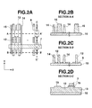
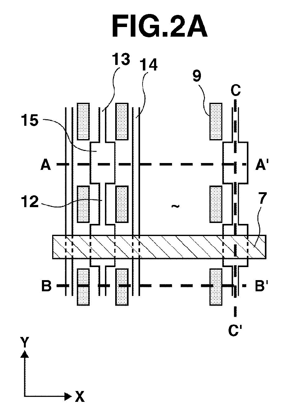
- Figs. 2A to 2D schematically illustrate the shapes of ribs formed on a face plate.
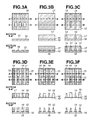
- Figs. 3A to 3F schematically illustrate a method for forming the face plate.
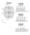
- Figs. 4A to 4F schematically illustrate the shapes of ribs formed on a face plate according to the first exemplary embodiment.
- Figs. 5A to 5D schematically illustrate the shapes of ribs formed on a face plate according to a second exemplary embodiment.
- Image display apparatuses are suitably applicable to electron beam display apparatuses, such as cathode ray tubes (CRTs) and field emission displays (FEDs), and to plasma display apparatuses.
- CRTs cathode ray tubes
- FEDs field emission displays
- plasma display apparatuses are suitably applicable to electron beam display apparatuses, such as cathode ray tubes (CRTs) and field emission displays (FEDs), and to plasma display apparatuses.
- CTRs cathode ray tubes
- FEDs field emission displays
- Fig. 1 is an exploded perspective view illustrating an image display apparatus according to a first exemplary embodiment of the present invention.
- the image display apparatus includes a rear plate (first substrate) 1, a face plate (second substrate) 10, and spacers 7 interposed between the rear plate 1 and the face plate 10.
- the hermetic container includes the rear plate 1, the face plate 10, and a frame member 6.
- the frame member 6 may be an individual unit separate from the rear plate 1 and the face plate 10, or may be a portion integral with the rear plate 1 or the face plate 10.
- Electron emitting devices 5 are provided on the inner surface (an inner surface of the hermetic container) of the rear plate 1.
- the electron emitting devices 5 may be cold-cathode electron emitting devices.
- the matrix of wires 2 is used to drive each electron emitting device 5 according to an image signal.
- light emitting members (phosphor pixels) 9 are provided on the inner surface of the face plate 10.
- the light emitting members 9 emit light when irradiated with electrons emitted from the electron emitting devices 5.
- the light emitting members 9 are provided in openings of a black matrix (not shown) formed on the face plate 10.
- the light emitting members 9 are colored with red (R), green (G), and blue (B) phosphors, for example.
- the set of electron emitting devices 5 and the set of light emitting members 9 are each arranged in a matrix of lines.
- ribs 13 and 14 are formed in straight lines, with each line of light emitting members 9 interposed between adjacent ribs 13 and 14. These protruding ribs 13 and 14 are higher than the light emitting members 9, and project beyond the light emitting members 9 toward the rear plate 1.
- the ribs 13 and 14 extend in one direction (the Y direction in the figure).
- the spacers 7 extend in a direction (the X direction in the figure) intersecting the ribs 13 and 14.
- the spacers 7 are disposed between the rear plate 1 and the face plate 10 to support the hermetic container from the inside and withstand atmospheric pressure applied to the hermetic container.
- Each spacer 7 is located between light emitting members 9 adjacent to each other in the Y direction.
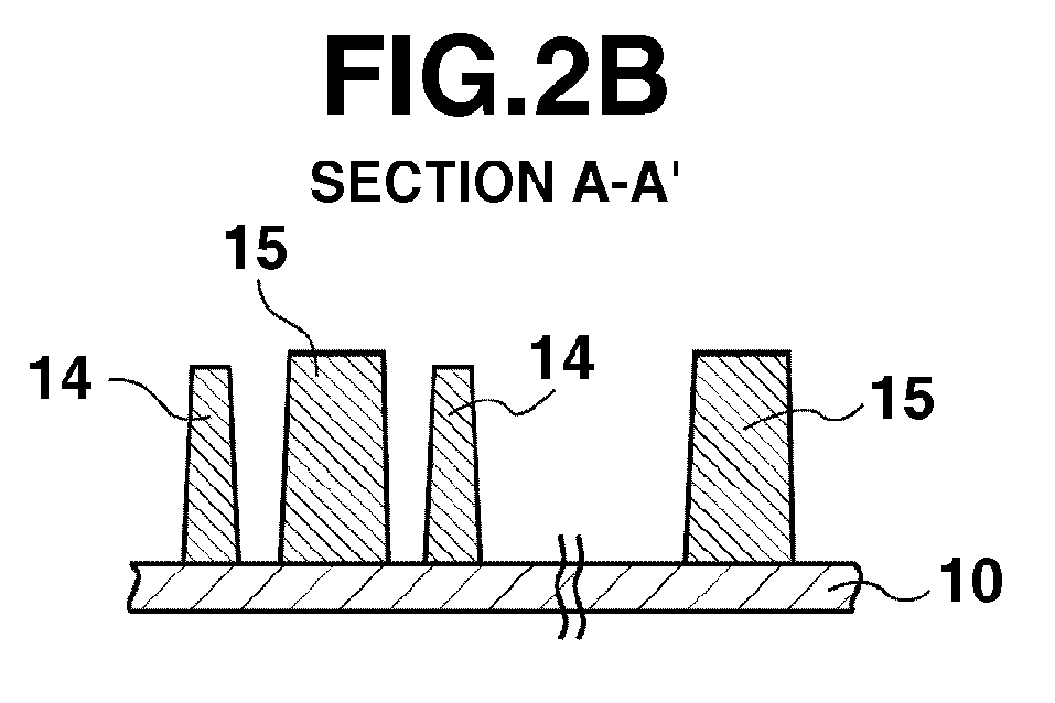
- Figs. 2A to 2D illustrate the shapes of the ribs 13 and 14 formed on the face plate 10.
- Fig. 2A is a schematic plan view illustrating the face plate 10 as viewed from above the surface thereof facing the rear plate 1.
- Figs. 2B, 2C, and 2D are schematic cross sectional views taken along the lines A-A', B-B', and C-C', respectively, of Fig. 2A.
- Figs. 2A to 2D illustrate the spacers 7, the ribs 13 and 14, and the phosphor pixels 9.
- the ribs 13 and 14 extend in the Y direction, and are aligned in the X direction.
- the ribs 13 have wide portions 15 (hereinafter referred to as "first ribs”)
- the ribs 14 have no wide portions 15 (hereinafter referred to as "second ribs”) . These two types of ribs are provided.
- the second ribs 14 of constant width each extend in a straight line.
- the first ribs 13 have general portions 12 and the wide portions 15. Each general portion 12 having substantially the same width as the second ribs 14 extends in a straight line.
- the wide portions 15 are formed to have a large width in the direction (the X direction) in which the spacers 7 extend.
- the wide portions 15 are formed in those parts of the first ribs 13 in which the first ribs 13 intersect the spacers 7.
- the wide portions 15 may be periodically formed in the direction (the Y direction) in which the first ribs 13 extend.
- the first and second ribs 13 and 14 function as a scattering shield for preventing or suppressing re-entry (halation) of backscattered electrons into the phosphor pixels 9.
- the wide portions 15 of the first ribs 13 are higher than the second ribs 14, more particularly, higher than those parts of the second ribs 14 in which the second ribs 14 intersect the spacers 7.
- the wide portions 15 are higher than the general portions 12 (the portions other than the wide portions 15) .
- the wide portions 15 may be higher than the second ribs 14 by about 2 to 10 ⁇ m.
- the wide portions 15 of the first ribs 13 are to abut on the spacers 7.
- the spacers 7 abut on the wide portions 15 that are higher than the other rib portions 12 and the second ribs 14.
- the second ribs 14, which are lower than the wide portions 15, do not abut on the spacers 7.
- the wide portions 15 of the first ribs 13 have higher shear strength (strength against shear) than the general portions 12 and the second ribs 14.
- the wide portions 15 have sufficiently high strength against the shear produced when the wide portions 15 abut on the spacers 7.
- the second ribs 14 having low shear strength do not abut on the spacers 7 or abut on the spacers 7 with a slight force applied thereto because the wide portions 15 support the spacers 7. Accordingly, even if misalignment or deformation, e.g., of the spacers 7 applies a shear force to the ribs 13 and 14, the possibility of failure of the ribs 13 and 14 is reduced.
- the ribs 13 and 14 need to be increased in width or reduced in height. However, if all of the ribs 13 and 14 have a large width, the spacing between adjacent ribs 13 and 14 is narrowed. Such narrowed spacing requires the light emitting members 9 between the ribs 13 and 14 to be reduced in size, resulting in lower-intensity light emitted from the light emitting members 9. If the ribs 13 and 14 are reduced in height, their function as a shield against electron scattering decreases, allowing halation to easily occur and possibly leading to degradation in the performance of the image display apparatus.
- first ribs 13 are provided with at least one second rib 14 disposed between adjacent first ribs 13.
- the ribs 13 having the wide portions 15 are not located adjacent to each other. This ensures the area where the light emitting members 9 are disposed, while increasing the strength of the wide portions 15 that abut on the spacers 7.
- all of the ribs 13 and 14 may be formed with the wide portions 15 having the largest possible width.
- the spacing between adjacent ribs is uniform, such uniform spacing imposes limitations on the formation of the wide portions 15 in all of the ribs 13 and 14. This is because the width of the wide portions 15 must be set smaller than the spacing between adjacent ribs.
- the width of the wide portions 15 can be increased by placing one or two second ribs 14 between adjacent first ribs 13 having the wide portions 15. This allows shear strength to be maximized even if the spacing between adjacent ribs is uniform.
- the width of the wide portions 15 in the direction in which the spacers 7 extend can be set greater than the spacing between light emitting members 9 in that direction.
- the wide portions 15 are formed higher than the second ribs 14 so as to prevent the spacers 7 from abutting on the second ribs 14, so that the wide portions 15 having high shear strength share a function of holding the spacers 7.
- the ribs 13 and 14 may vary in height to some degree.
- the first ribs 13 have the wide portions 15 formed to abut on the spacers 7, all of the wide portions 15 need not abut on the spacers 7 in the resultant apparatus.
- the second ribs 14, formed so as not to abut on the spacers 7, may abut on the spacers 7 in the resultant apparatus. Even in those cases, the possibility of failure of the second ribs 14 is reduced because the wide portions 15 higher than the second ribs 14 reduce the force (shear force) applied from the spacers 7 to the second ribs 14.
- the width of the wide portions 15 of the first ribs 13 may be determined depending on the number, shear strength, and compressive strength of the first ribs 13.
- the shear strength (bending strength) of ribs is inversely proportional to stress applied to the bottoms of the ribs.
- the shear strength (bending strength) of ribs is proportional to the square of the width of the ribs, and inversely proportional to the magnitude of shear load applied to each rib and the height of the ribs.
- the shear load applied to each first rib 13 is a reciprocal of the ratio of the number of first ribs 13 to the total number of first and second ribs 13 and 14. For example, suppose that half of all ribs 13 and 14 are the first ribs 13. In that case, the shear load per rib doubles as compared to when all of the ribs 13 and 14 abut on the spacers 7. When one third of all ribs 13 and 14 are the first ribs 13, the shear load per rib triples.
- the width of the wide portions 15 may be set as follows.
- the width of the wide portions 15 of the first ribs 13 may be set equal to or greater than (1/R) 1/2 times the width, in the X direction, of the parts of the second ribs 14 in which the second ribs 14 intersect the spacers 7, where R is the ratio of the number of first ribs 13 to the total number of ribs 13 and 14.
- the width of the wide portions 15 may be set equal to or greater than 2 1/2 times that of the second ribs 14.
- the width of the wide portions 15 may be set equal to or greater than 3 1/2 times that of the second ribs 14.
- the wide portions 15 of such width enhance the strength against shear force applied to each rib (wide portion 15) as compared to when all ribs 13 and 14, each having no wide portions, are in abutment on the spacers 7.
- the compressive strength of ribs is proportional to the abut area in which the ribs abut on the spacers 7. This abutting area is proportional to the product of the width of the wide portions 15 of the first ribs 13, the width of the spacers 7, and the number of first ribs 13. Providing one first rib 13 for each one or two second ribs 14 ensures such width of the wide portions 15 as increasing the shear strength as compared to the conventional example, while allowing the compressive strength to be maintained at a sufficiently high level.
- FIG. 3A to 3F illustrate a method for forming ribs on a substrate (face plate) in an image display device.
- a glass substrate 10 with a black matrix 16 formed thereon is prepared.
- the black matrix 16 has a predetermined pattern in which openings are formed in portions where phosphor pixels 9 are to be provided (see Fig. 3A ) .
- a soda lime glass for example, (e.g., a glass substrate PD 200 for PDP manufactured by ASAHI GLASS CO., LTD) may be used.
- a paste 17 for ribs is applied in a uniform thickness to the entire surface of the glass substrate 10 (see Fig. 3B ) .
- a photo paste containing at least a glass component and a photo-curing resin may be used as the paste 17 for ribs.
- the paste 17 may contain a solvent and/or an initiator, for example.
- the paste for ribs 17 may be applied by screen printing, slit coating, or other method. However, considering the rib height (about 20 to 200 ⁇ m) required to suppress halation, slit coating is suitable.
- exposure patterns 14 and 15 of straight lines are formed in the photo paste 17.
- the lines of the exposure patterns 14 and 15 correspond to the parts to be left as ribs in a later step, and thus are given the same reference numerals as those corresponding rib portions and ribs described above.
- the lines of the patterns 14 and 12 corresponding only to the second ribs 14 and the general portions 12 of the first ribs 13 are exposed to light (see Fig. 3C ).
- the wide exposure portions 15 corresponding only to the wide portions 15 of the first ribs 13 are exposed to light (see Fig. 3D ).
- at least one line of a first exposure pattern 13 has the wide exposure portions 15 having a large width in a second direction intersecting a first direction in which the lines of the exposure patterns extend.
- the lines of the second exposure pattern 14 have a constant width in the second direction. Either the exposure of the patterns 14 and 12 corresponding to the second ribs 14 and the general portions 12 of the first ribs 13 or the exposure of the wide exposure portions 15 corresponding to the wide portions 15 may be performed first.
- Differences in rib height occur during baking. Such differences in height are achieved by utilizing differences in shrinkage between the wide portions (the wide exposure portions) 15 of the first ribs 13 and the general portions (the parts of the first exposure portions other than the wide exposure portions) 12 of the first ribs 13 and between the wide portions (the wide exposure portions) 15 and the second ribs (the second exposure portions) 14.
- the ribs 13 and 14 shrink because the resin in the paste 17 is decomposed during baking to create voids, and those voids are filled with the glass component heated to a temperature equal to or higher than a glass-transition temperature.
- the amount of resin in the paste 17 may be increased, and a glass component whose glass-transition temperature is sufficiently lower than the baking temperature may be used. Then, the shrinkage of the wide portions 15 increases, enabling differences in rib height to be produced.
- the solid content in the paste 17 may contain 30 to 70 wt% of resin, more preferably 40 to 60 wt% of resin.
- the glass component may contain a high percentage of borosilicate glass as a low softening point substance. Desired differences in the height of the ribs 13 and 14 can be easily produced by developing and baking all of the exposure patterns together as set forth above.
- the wide exposure portions 15, and the exposure portions other than the wide exposure portions 15 may be exposed separately, and a dose of exposure for the wide exposure portions 15 may be greater than that for the other exposure portions. Then, the degree of resin cross-linking and the amount of resin to be cured can be changed to produce differences in the amount of resin decomposed during baking and thereby adjust the height of the ribs.
- a higher degree of cross-linking in the wide portions 15 results in a smaller amount of resin elution during development, thus allowing a larger amount of resin to remain in the wide portions 15.
- the amount of resin eluted during development is large, resulting in a small amount of resin remaining therein. Consequently, during baking, the wide portions 15 in which a large amount of resin remains shrink considerably, while the general portions 12 and the second ribs 14 in which a small amount of resin is left shrink slightly. This method can produce further differences in rib height.
- a method for fabricating an image display apparatus using a face plate 10 with ribs 13 and 14 formed thereon will be described.
- light emitting members 9 are formed in openings in a black matrix 16 on the face plate 10.
- a metal back (not shown) is then formed on the light emitting members 9.
- a rear plate 1 having electron emitting devices 5 thereon is prepared.
- the rear plate 1 and the face plate 10 are placed to face each other with spacers 7 interposed therebetween, forming a hermetic container in which airtightness is maintained.
- Figs. 4A to 4D illustrate the structure of the face plate 10 in the first exemplary embodiment.
- Fig. 4A is a plan view illustrating the face plate 10.
- Figs. 4B, 4C, and 4D are cross sectional views taken along the lines A-A' , B-B' , and C-C', respectively, of Fig. 4A .
- the first ribs 13 having the wide portions 15 and the second ribs 14 having no wide portions 15 are provided alternately. These ribs 13 and 14 are formed on both sides of lines of phosphor pixels 9 so that each line of phosphor pixels 9 is located between adjacent ribs 13 and 14. The number of ribs 13 and 14 formed corresponds to the number of lines of phosphor pixels 9.
- Figs. 4A to 4D illustrate the spacers 7, the first ribs 13, the second ribs 14, and the phosphor pixels 9.
- the wide portions 15 of the first ribs 13 are located between adjacent phosphor pixels 9 arranged in a line, and fifteen wide portions 15 are periodically provided.
- the width of the wide portions 15 is increased in the direction (X direction) perpendicular to the direction in which the ribs 13 and 14 extend.
- the image display apparatus includes 25 spacers 7.
- each wide portion 15 has a width of 125 ⁇ m, and the top of each general portion 12 has a width of 55 ⁇ m.
- the width of the top of each second rib 14 is 55 ⁇ m.
- the bottom of each wide portion 15 has a width of 170 ⁇ m, and the bottom of each general portion 12 has a width of 78 ⁇ m.
- the width of the bottom of each second rib 14 is 78 ⁇ m.
- each wide portion 15 has a height of 205 ⁇ m, and each general portion 12 has a height of 196 ⁇ m.
- the height of each second rib 14 is 200 ⁇ m.
- each phosphor pixel 9 are 106 ⁇ m in the X direction by 250 ⁇ m in the Y direction.
- each wide portion 15 of the first ribs 13 are both greater than twice the respective widths of the top and bottom of each second rib 14 (the top: 2.27 times, the bottom: 2.18 times) .
- the dimensions of these members are such that compressive strength and shear strength are both enhanced as compared to the conventional rib structure. Actual measured values of compressive strength and shear strength will be provided later.
- the wide portions 15 of the first ribs 13 are higher than the general portions 12 of the first ribs 13, and higher than the second ribs 14 that are adjacent to the wide portions 15 in the X direction.
- the first ribs 13 are to abut on the spacers 7.
- the spacers 7 abut on some or all of the wide portions 15 that are higher than the other rib portions 12 and the second ribs 14.
- the first ribs 13 also prevent backscattered electrons from re-entering the phosphors, to thereby reduce halation.
- the second ribs 14, which do not abut on the spacers 7, prevent backscattered electrons from re-entering the phosphors, to thereby reduce halation.
- a method for forming the ribs according to the present exemplary embodiment will be described.
- the rib formation method is the same as the method set forth above. Hence, in the following, conditions in each process step will be described.
- a paste (photosensitive paste TPR-8100 manufactured by Toray Industries Inc.) containing borosilicate glass powder is applied, using a slit coater, to the entire surface of the glass substrate 10 in a thickness of 476 ⁇ m .
- the coated glass substrate 10 is dried at 95°C for 60 minutes, and then subjected to proximity exposure processes.
- the first exposure process only the exposure portions (the portions other than the wide exposure portions 15) having a constant width and extending in straight lines are exposed to light with a gap of 450 ⁇ m and an exposure dose of 290 mJ/cm 2 .
- the second exposure process only the wide exposure portions 15 are exposed to light with a gap of 450 ⁇ m and an exposure dose of 350 mJ/cm 2 .
- the glass substrate 10 is baked at 110°C for 7 minutes. Then, the glass substrate 10 is subjected, for 390 seconds, to a development process using a liquid developer containing 0 . 5 wt% of sodium carbonate. The glass substrate 10 is then rinsed with water for 180 seconds to remove unnecessary paste. After the development process, the glass substrate 10 is baked at 580°C for 28 minutes. After the baking process, the ribs of the above-described dimensions are obtained.
- the shear strength of the ribs formed in the present exemplary embodiment was measured in the following manner.
- the substrate 10 was placed so that the X direction thereof was perpendicular to the ground with the side faces of the ribs 14 and 15 facing upwardly.
- the indenter was then vertically lowered to place a load on the top of the rib.
- the value of the load at the time when the failure of the rib occurred was measured as the shear strength.
- the shear strength of the ribs having the wide portions 15 according to the present exemplary embodiment was 0.85 N, while the shear strength of conventional structure ribs of constant width was 0.25 N.
- the ribs according to the present exemplary embodiment have the enhanced shear strength as compared to the conventional example.
- the result of measurement of the shear strength of the conventional rib structure will be provided later (Comparative Example 1).
- the compressive strength of the ribs formed according to the present exemplary embodiment was measured in the following manner.
- the compressive strength was measured by performing a compressive crush test using a microcompression tester (MCT-W500 manufactured by Shimadzu Corporation).
- MCT-W500 manufactured by Shimadzu Corporation.
- a flat indenter 50 ⁇ m in diameter was lowered from its position directly above the rib to apply a compressive load on the rib until the failure of the rib occurred.
- the value of the load at the time of the occurrence of the rib failure was measured as the compressive strength.
- the compressive strength of the wide portions 15 according to the present exemplary embodiment was equal to or higher than 1500 MPa (equal to or higher than the upper limit of the measuring range of the tester), while the compressive strength of the conventional structure ribs of constant width was 1500 MPa.
- the wide portions 15 according to the present exemplary embodiment have the enhanced compressive strength as compared to the conventional example.
- the result of measurement of the compressive strength of the conventional rib structure will be provided later (Comparative Example 1).
- An image display apparatus was assembled using a face plate 10 having thereon ribs 13 and 14 according to the first exemplary embodiment, a rear plate 1 having thereon electron emitting devices 5, and spacers 7. Then the ribs 13 and 14 were checked whether there were failures.
- the image display apparatus was assembled in the following manner.
- the spacers 7 and a frame member 6 were fixed on the rear plate 1 by jointing material.
- the rear plate 1 with the spacers 7 fixed thereon and the face plate 10 were aligned so that the electron emitting devices 5 and light emitting members 9 faced each other.
- the rear plate 1 and the face plate 10 were placed so that the spacers 7 and the wide portions 15 of the first ribs 13 on the face plate 10 abutted on each other.
- a sealing material was applied to the frame member 6 and then heated until melted, to thereby bond the peripheral portion of the face plate 10 and the rear plate 1. Then, the air was exhausted from the bonded structure through an exhaust pipe (not shown) provided in the rear plate 1, thereby forming an evacuated hermetic container.
- the hermetic container was disassembled to check for failure of the ribs 13 and 14.
- the rib structure formed according to the first exemplary embodiment produced a further increase in the shear strength of the ribs 13 and 14 to thereby prevent failure of the ribs 13 and 14 when the spacers 7 abutted on the ribs 13 and 14. This also provides design freedom in high definition displays.
- the phosphor pixels 9 and the pixels are both spaced uniformly.
- the pitch distance between adjacent pixels may be nonuniform.
- a second exemplary embodiment employing a nonuniform pitch will be described below.
- Figs. 5A to 5D illustrate the shapes of ribs according to the second exemplary embodiment of the present invention.
- Figs. 5A to 5D illustrate a structure in which two second ribs 14 having no wide portions 15 are present between two first ribs 13 having wide portions 15.
- Fig. 5A is a plan view illustrating a face plate 10.
- Figs. 5B, 5C, and 5D are cross sectional views taken along the lines A-A', B-B' , and C-C', respectively, of Fig. 5A .
- the first and second ribs 13 and 14 according to the present exemplary embodiment have approximately the same dimensions as those in the first exemplary embodiment. Thus, only differences will be described below.
- each wide portion 15 of the first ribs 13 have a width of 160 ⁇ m and 225 ⁇ m, respectively.
- the spacing between the tops of adjacent first and second ribs 13 and 14 is 120 ⁇ m both when the wide-portion-to-general-portion distance is measured and when the general-portion-to-general-portion distance is measured.
- the pixel pitch in the X direction is not uniform.
- the respective widths of the top and bottom of each wide portion 15 of the first ribs 13 are both about three times greater than the respective widths of the top and bottom of each second rib 14 (the top: 2.91 times, the bottom: 2.88 times) .
- the compressive strength is equal to that of the conventional rib structure (Comparative Example 1) , while the ribs are formed to have enhanced shear strength as compared to the conventional rib structure. Actual measured values of the compressive strength and shear strength will be provided later.
- the wide portions 15 of the first ribs 13 are higher than the general portions 12 of the first ribs 13, and higher than the second ribs 14 adjacent to the wide portions 15 in the X direction.
- the first ribs 13 are to abut on the spacers 7.
- the spacers 7 abut on some or all of the wide portions 15 that are higher than the other rib portions 12 and the second ribs 14.
- the first ribs 13 also prevent backscattered electrons from re-entering the phosphor pixels 9, to thereby reduce halation.
- the second ribs 14, which do not abut on the spacers 7, prevent backscattered electrons from re-entering the phosphor pixels 9, to thereby reduce halation.
- a method for forming the ribs according to the second exemplary embodiment is the same as that in the first exemplary embodiment.
- the shear strength of the ribs formed in the second exemplary embodiment is 0.85 N, which is enhanced as compared to the conventional rib structure.
- the shear strength was measured in the same manner as in the first exemplary embodiment.
- the compressive strength is 1500 MPa, which is equal to that of the conventional rib structure.
- the image display apparatus according to the second exemplary embodiment was assembled and disassembled in the same ways as in the first exemplary embodiment. It was confirmed that the ribs formed according to the second exemplary embodiment achieved enhancing of shear strength to thereby prevent rib failure when the spacers 7 abutted on the ribs. This also provides design freedom in high definition displays.
- An image display apparatus includes first(1) and second(10) substrates , an electron emitting device(5), light emitting members ( 9 ) , and a spacer (7) located between the first and second substrates.
- Straight-line ribs (13) , (14) higher than the light emitting members are formed on the second substrate with one of the lines of light emitting members interposed between each adjacent pair of ribs.
- the spacer extends in a second direction intersecting a first direction in which the ribs extend, and is located between the light emitting members adjacent to each other in the first direction.
- the ribs include first and second ribs, and each first rib includes a wide portion(15) where it intersects the spacer, the wide portion having a large width in the second direction and being higher than parts of the second ribs intersecting the spacer, at least one of the second ribs being disposed between each adjacent pair of first ribs.
Landscapes
- Engineering & Computer Science (AREA)
- Manufacturing & Machinery (AREA)
- Vessels, Lead-In Wires, Accessory Apparatuses For Cathode-Ray Tubes (AREA)
- Cathode-Ray Tubes And Fluorescent Screens For Display (AREA)
Abstract
An image display apparatus includes first(1) and second(10) substrates , an electron emitting device(5), light emitting members(9) , and a spacer (7) located between the first and second substrates. Straight-line ribs(13),(14) higher than the light emitting members are formed on the second substrate with one of the lines of light emitting members interposed between each adjacent pair of ribs. The spacer extends in a second direction intersecting a first direction in which the ribs extend, and is located between the light emitting members adjacent to each other in the first direction. The ribs include first and second ribs, and each first rib includes a wide portion(15) where it intersects the spacer, the wide portion having a large width in the second direction and being higher than parts of the second ribs intersecting the spacer, at least one of the second ribs being disposed between each adjacent pair of first ribs.

Description
- The present invention relates to an image display apparatus including electron emitting devices, and a method for forming ribs on a substrate in an image display apparatus.
- An image display apparatus including electron emitting devices may include a rear plate and a face plate. The electron emitting devices are formed on the rear plate. On the face plate, light emitting members are formed which emit light when irradiated with electrons emitted from the electron emitting devices. The electron emitting devices are operated in a thin hermetic container (a vacuum container) composed of the rear plate, the face plate, and other members. Hence, the hermetic container needs to have an atmospheric-pressure-resistant structure.
- In manufacturing a large-area, thin image display apparatus, in light of weight and cost, spacers for providing resistance to atmospheric pressure are disposed as supports between a rear plate and a face plate.
- Japanese Patent Application Laid-Open No.
02-299136 2000-348651 - Japanese Unexamined Patent Application Publication (Translation of PCT Application) No.
2000-500613 - In a structure in which spacers abut on ribs formed on a face plate, if the ribs have a uniform height, the load imposed by the spacers can be distributed among all ribs. However, despite efforts to form ribs of desired height, the resultant ribs vary in height to some extent. Consequently, the spacers may abut on ribs of higher height only.
- When such ribs of various heights abut on spacers in assembling an image display apparatus, a shear force may be applied to the ribs due to, e.g., misalignment or deformation of the spacers. In that case, the magnitude of the shear force applied also varies among the ribs according to the variations in the height of the ribs. When only a few ribs have higher height, a shear stress produced in those ribs being in abutment on the spacers is increased, which may cause failure of the ribs.
- To ensure the strength of the ribs, the ribs may be increased in width. However, the width of the ribs can be increased only to a limited extent because of limitations on the available area where other members, such as light emitting members, are also disposed. If, to overcome these area limitations, ribs of narrower width are formed, rib failure may occur when the spacers abut on those narrow-width ribs.
- According to the present invention, there is provided an image display apparatus capable of preventing the possibility of failure of ribs. There is also provided a method for easily forming ribs on a substrate (face plate) in an image display apparatus.
- In an image display apparatus according to an exemplary embodiment of the present invention, parts of ribs that abut firmly on spacers have a large width to enhance the shear strength of the ribs. The enhanced shear strength reduces the possibility of rib failure occurring due to misalignment or deformation of the atmospheric-pressure-resistant spacers and due to variations in the rib height when the spacers abut on the ribs.
- According to a rib formation method in accordance with the present invention, straight-line ribs of constant width and straight-line ribs including a wide portion higher and wider than the straight-line ribs are easily formed on a substrate.
- The present invention in its first aspect provides an image display apparatus as specified in
claims 1 to 5. - The present invention in its second aspect provides a method for forming, on a substrate, straight-line ribs of constant width and straight-line ribs including a wide portion higher and wider than the straight-line ribs as specified in
claims 6 and 7. - Further features and aspects of the present invention will become apparent from the following detailed description of exemplary embodiments with reference to the attached drawings.
- The accompanying drawings, which are incorporated in and constitute a part of the specification, illustrate exemplary embodiments, features, and aspects of the invention and, together with the description, serve to explain the principles of the invention.
-
Fig. 1 is an exploded perspective view illustrating an image display apparatus according to a first exemplary embodiment of the present invention. -
Figs. 2A to 2D schematically illustrate the shapes of ribs formed on a face plate. -
Figs. 3A to 3F schematically illustrate a method for forming the face plate. -
Figs. 4A to 4F schematically illustrate the shapes of ribs formed on a face plate according to the first exemplary embodiment. -
Figs. 5A to 5D schematically illustrate the shapes of ribs formed on a face plate according to a second exemplary embodiment. - Various exemplary embodiments, features, and aspects of the invention will be described in detail below with reference to the drawings.
- Image display apparatuses according to exemplary embodiments of the present invention are suitably applicable to electron beam display apparatuses, such as cathode ray tubes (CRTs) and field emission displays (FEDs), and to plasma display apparatuses. In particular, FEDs, in which spacers define the clearance between a face plate and a rear plate which configure a vacuum container, are a suitable form to which the present invention is applicable.
-
Fig. 1 is an exploded perspective view illustrating an image display apparatus according to a first exemplary embodiment of the present invention. The image display apparatus includes a rear plate (first substrate) 1, a face plate (second substrate) 10, andspacers 7 interposed between therear plate 1 and theface plate 10. Therear plate 1 and theface plate 10, disposed to face each other, form a hermetic container in which the pressure is reduced. - Specifically, the hermetic container includes the
rear plate 1, theface plate 10, and a frame member 6. The frame member 6 may be an individual unit separate from therear plate 1 and theface plate 10, or may be a portion integral with therear plate 1 or theface plate 10. -
Electron emitting devices 5 are provided on the inner surface (an inner surface of the hermetic container) of therear plate 1. Theelectron emitting devices 5 may be cold-cathode electron emitting devices. On therear plate 1, a matrix ofwires 2, composed ofX-direction wires 3 and Y-direction wires 4, is formed. The matrix ofwires 2 is used to drive eachelectron emitting device 5 according to an image signal. - On the inner surface of the
face plate 10, light emitting members (phosphor pixels) 9 are provided. Thelight emitting members 9 emit light when irradiated with electrons emitted from theelectron emitting devices 5. Thelight emitting members 9 are provided in openings of a black matrix (not shown) formed on theface plate 10. Thelight emitting members 9 are colored with red (R), green (G), and blue (B) phosphors, for example. - The set of
electron emitting devices 5 and the set oflight emitting members 9 are each arranged in a matrix of lines. On theface plate 10,ribs light emitting members 9 interposed betweenadjacent ribs protruding ribs light emitting members 9, and project beyond thelight emitting members 9 toward therear plate 1. Theribs - The
spacers 7 extend in a direction (the X direction in the figure) intersecting theribs spacers 7 are disposed between therear plate 1 and theface plate 10 to support the hermetic container from the inside and withstand atmospheric pressure applied to the hermetic container. Eachspacer 7 is located between light emittingmembers 9 adjacent to each other in the Y direction. -
Figs. 2A to 2D illustrate the shapes of theribs face plate 10.Fig. 2A is a schematic plan view illustrating theface plate 10 as viewed from above the surface thereof facing therear plate 1.Figs. 2B, 2C, and 2D are schematic cross sectional views taken along the lines A-A', B-B', and C-C', respectively, ofFig. 2A. Figs. 2A to 2D illustrate thespacers 7, theribs phosphor pixels 9. - In the present exemplary embodiment, the
ribs ribs 13 have wide portions 15 (hereinafter referred to as "first ribs") , and theribs 14 have no wide portions 15 (hereinafter referred to as "second ribs") . These two types of ribs are provided. - In the present exemplary embodiment, the
second ribs 14 of constant width each extend in a straight line. Thefirst ribs 13 havegeneral portions 12 and thewide portions 15. Eachgeneral portion 12 having substantially the same width as thesecond ribs 14 extends in a straight line. Thewide portions 15 are formed to have a large width in the direction (the X direction) in which thespacers 7 extend. Thewide portions 15 are formed in those parts of thefirst ribs 13 in which thefirst ribs 13 intersect thespacers 7. Thewide portions 15 may be periodically formed in the direction (the Y direction) in which thefirst ribs 13 extend. The first andsecond ribs phosphor pixels 9. - The
wide portions 15 of thefirst ribs 13 are higher than thesecond ribs 14, more particularly, higher than those parts of thesecond ribs 14 in which thesecond ribs 14 intersect thespacers 7. In the present exemplary embodiment, thewide portions 15 are higher than the general portions 12 (the portions other than the wide portions 15) . For example, when thesecond ribs 14 have a height of 200 µm, thewide portions 15 may be higher than thesecond ribs 14 by about 2 to 10 µm. - The
wide portions 15 of thefirst ribs 13 are to abut on thespacers 7. Thus, thespacers 7 abut on thewide portions 15 that are higher than theother rib portions 12 and thesecond ribs 14. On the other hand thesecond ribs 14, which are lower than thewide portions 15, do not abut on thespacers 7. - In the present exemplary embodiment, the
wide portions 15 of thefirst ribs 13 have higher shear strength (strength against shear) than thegeneral portions 12 and thesecond ribs 14. Thus, thewide portions 15 have sufficiently high strength against the shear produced when thewide portions 15 abut on thespacers 7. Even if theribs second ribs 14 having low shear strength do not abut on thespacers 7 or abut on thespacers 7 with a slight force applied thereto because thewide portions 15 support thespacers 7. Accordingly, even if misalignment or deformation, e.g., of thespacers 7 applies a shear force to theribs ribs - Generally, to enhance the shear strength of the
ribs ribs ribs adjacent ribs light emitting members 9 between theribs light emitting members 9. If theribs - In the present exemplary embodiment, two or more
first ribs 13 are provided with at least onesecond rib 14 disposed between adjacentfirst ribs 13. Hence, theribs 13 having thewide portions 15 are not located adjacent to each other. This ensures the area where thelight emitting members 9 are disposed, while increasing the strength of thewide portions 15 that abut on thespacers 7. - To increase shear strength, all of the
ribs wide portions 15 having the largest possible width. However, when the spacing between adjacent ribs is uniform, such uniform spacing imposes limitations on the formation of thewide portions 15 in all of theribs wide portions 15 must be set smaller than the spacing between adjacent ribs. - Nevertheless, the width of the
wide portions 15 can be increased by placing one or twosecond ribs 14 between adjacentfirst ribs 13 having thewide portions 15. This allows shear strength to be maximized even if the spacing between adjacent ribs is uniform. In particular, the width of thewide portions 15 in the direction in which thespacers 7 extend can be set greater than the spacing betweenlight emitting members 9 in that direction. - As set forth above, the
wide portions 15 are formed higher than thesecond ribs 14 so as to prevent thespacers 7 from abutting on thesecond ribs 14, so that thewide portions 15 having high shear strength share a function of holding thespacers 7. However, theribs first ribs 13 have thewide portions 15 formed to abut on thespacers 7, all of thewide portions 15 need not abut on thespacers 7 in the resultant apparatus. Likewise, thesecond ribs 14, formed so as not to abut on thespacers 7, may abut on thespacers 7 in the resultant apparatus. Even in those cases, the possibility of failure of thesecond ribs 14 is reduced because thewide portions 15 higher than thesecond ribs 14 reduce the force (shear force) applied from thespacers 7 to thesecond ribs 14. - The width of the
wide portions 15 of thefirst ribs 13 may be determined depending on the number, shear strength, and compressive strength of thefirst ribs 13. The shear strength (bending strength) of ribs is inversely proportional to stress applied to the bottoms of the ribs. Hence, the shear strength (bending strength) of ribs is proportional to the square of the width of the ribs, and inversely proportional to the magnitude of shear load applied to each rib and the height of the ribs. - The shear load applied to each
first rib 13 is a reciprocal of the ratio of the number offirst ribs 13 to the total number of first andsecond ribs ribs first ribs 13. In that case, the shear load per rib doubles as compared to when all of theribs spacers 7. When one third of allribs first ribs 13, the shear load per rib triples. - Hence, to increase the ribs' shear strength as compared to a case where none of the
ribs wide portions 15, and thus all of theribs spacers 7, the width of thewide portions 15 may be set as follows. The width of thewide portions 15 of thefirst ribs 13 may be set equal to or greater than (1/R) 1/2 times the width, in the X direction, of the parts of thesecond ribs 14 in which thesecond ribs 14 intersect thespacers 7, where R is the ratio of the number offirst ribs 13 to the total number ofribs - For example, when half of the total number of
ribs first ribs 13, the width of thewide portions 15 may be set equal to or greater than 21/2 times that of thesecond ribs 14. When one third of allribs first ribs 13, the width of thewide portions 15 may be set equal to or greater than 31/2 times that of thesecond ribs 14. Thewide portions 15 of such width enhance the strength against shear force applied to each rib (wide portion 15) as compared to when allribs spacers 7. - The compressive strength of ribs is proportional to the abut area in which the ribs abut on the
spacers 7. This abutting area is proportional to the product of the width of thewide portions 15 of thefirst ribs 13, the width of thespacers 7, and the number offirst ribs 13. Providing onefirst rib 13 for each one or twosecond ribs 14 ensures such width of thewide portions 15 as increasing the shear strength as compared to the conventional example, while allowing the compressive strength to be maintained at a sufficiently high level. - A method for forming ribs on a substrate will be described with reference to
Figs. 3A to 3F. Figs. 3A to 3F illustrate a method for forming ribs on a substrate (face plate) in an image display device. - First, a
glass substrate 10 with ablack matrix 16 formed thereon is prepared. Theblack matrix 16 has a predetermined pattern in which openings are formed in portions wherephosphor pixels 9 are to be provided (seeFig. 3A ) . As theglass substrate 10, a soda lime glass, for example, (e.g., a glass substrate PD 200 for PDP manufactured by ASAHI GLASS CO., LTD) may be used. - Next, a
paste 17 for ribs is applied in a uniform thickness to the entire surface of the glass substrate 10 (seeFig. 3B ) . As thepaste 17 for ribs, a photo paste containing at least a glass component and a photo-curing resin may be used. Thepaste 17 may contain a solvent and/or an initiator, for example. The paste forribs 17 may be applied by screen printing, slit coating, or other method. However, considering the rib height (about 20 to 200 µm) required to suppress halation, slit coating is suitable. - Subsequently, in an exposure step,
exposure patterns photo paste 17. The lines of theexposure patterns - Specifically, the lines of the
patterns second ribs 14 and thegeneral portions 12 of thefirst ribs 13 are exposed to light (seeFig. 3C ). Then, thewide exposure portions 15 corresponding only to thewide portions 15 of thefirst ribs 13 are exposed to light (seeFig. 3D ). More specifically, of the lines of the exposure patterns, at least one line of afirst exposure pattern 13 has thewide exposure portions 15 having a large width in a second direction intersecting a first direction in which the lines of the exposure patterns extend. The lines of thesecond exposure pattern 14 have a constant width in the second direction. Either the exposure of thepatterns second ribs 14 and thegeneral portions 12 of thefirst ribs 13 or the exposure of thewide exposure portions 15 corresponding to thewide portions 15 may be performed first. - Then, all of the exposure patterns are developed and baked together. Specifically, unnecessary parts of the paste for
ribs 17 are removed by development (seeFig. 3E ). After development, theribs substrate 10 by baking (seeFig. 3F ). - Differences in rib height occur during baking. Such differences in height are achieved by utilizing differences in shrinkage between the wide portions (the wide exposure portions) 15 of the
first ribs 13 and the general portions (the parts of the first exposure portions other than the wide exposure portions) 12 of thefirst ribs 13 and between the wide portions (the wide exposure portions) 15 and the second ribs (the second exposure portions) 14. - The
wide portions 15, which are large in volume, shrink considerably, while thegeneral portions 12 other than thewide portions 15, and thesecond ribs 14 shrink slightly. Accordingly, when thewide portions 15 and thegeneral portions 12 connected together shrink at the same time, thepaste 17 moves to thewide portions 15 that shrink more. This results in deformation of thepaste 17, producing height differences between theribs ribs wide portions 15 of thefirst ribs 13 can be formed higher than thegeneral portions 12 and thesecond ribs 14. - Presumably, the
ribs paste 17 is decomposed during baking to create voids, and those voids are filled with the glass component heated to a temperature equal to or higher than a glass-transition temperature. - Therefore, to adjust the amount of shrinkage, the amount of resin in the
paste 17 may be increased, and a glass component whose glass-transition temperature is sufficiently lower than the baking temperature may be used. Then, the shrinkage of thewide portions 15 increases, enabling differences in rib height to be produced. - For example, the solid content in the
paste 17 may contain 30 to 70 wt% of resin, more preferably 40 to 60 wt% of resin. The glass component may contain a high percentage of borosilicate glass as a low softening point substance. Desired differences in the height of theribs - In the exposure step, the
wide exposure portions 15, and the exposure portions other than thewide exposure portions 15 may be exposed separately, and a dose of exposure for thewide exposure portions 15 may be greater than that for the other exposure portions. Then, the degree of resin cross-linking and the amount of resin to be cured can be changed to produce differences in the amount of resin decomposed during baking and thereby adjust the height of the ribs. - Specifically, a higher degree of cross-linking in the
wide portions 15 results in a smaller amount of resin elution during development, thus allowing a larger amount of resin to remain in thewide portions 15. Contrary to this, in thegeneral portions 12 and thesecond ribs 14 having a lower degree of cross-linking than thewide portions 15, the amount of resin eluted during development is large, resulting in a small amount of resin remaining therein. Consequently, during baking, thewide portions 15 in which a large amount of resin remains shrink considerably, while thegeneral portions 12 and thesecond ribs 14 in which a small amount of resin is left shrink slightly. This method can produce further differences in rib height. - A method for fabricating an image display apparatus using a
face plate 10 withribs light emitting members 9 are formed in openings in ablack matrix 16 on theface plate 10. A metal back (not shown) is then formed on thelight emitting members 9. Arear plate 1 havingelectron emitting devices 5 thereon is prepared. Therear plate 1 and theface plate 10 are placed to face each other withspacers 7 interposed therebetween, forming a hermetic container in which airtightness is maintained. -
Figs. 4A to 4D illustrate the structure of theface plate 10 in the first exemplary embodiment.Fig. 4A is a plan view illustrating theface plate 10.Figs. 4B, 4C, and 4D are cross sectional views taken along the lines A-A' , B-B' , and C-C', respectively, ofFig. 4A . - In
Figs. 4A to 4D , thefirst ribs 13 having thewide portions 15 and thesecond ribs 14 having nowide portions 15 are provided alternately. Theseribs phosphor pixels 9 so that each line ofphosphor pixels 9 is located betweenadjacent ribs ribs phosphor pixels 9. -
Figs. 4A to 4D illustrate thespacers 7, thefirst ribs 13, thesecond ribs 14, and thephosphor pixels 9. Thewide portions 15 of thefirst ribs 13 are located between adjacentphosphor pixels 9 arranged in a line, and fifteenwide portions 15 are periodically provided. The width of thewide portions 15 is increased in the direction (X direction) perpendicular to the direction in which theribs spacers 7. - The dimensions of the members in the present exemplary embodiment are as follows. In the
first ribs 13, the top of eachwide portion 15 has a width of 125 µm, and the top of eachgeneral portion 12 has a width of 55 µm. The width of the top of eachsecond rib 14 is 55 µm. In thefirst ribs 13, the bottom of eachwide portion 15 has a width of 170 µm, and the bottom of eachgeneral portion 12 has a width of 78 µm. The width of the bottom of eachsecond rib 14 is 78 µm. In thefirst ribs 13, eachwide portion 15 has a height of 205 µm, and eachgeneral portion 12 has a height of 196 µm. The height of eachsecond rib 14 is 200 µm. The spacings between the tops of adjacent first andsecond ribs general portions general portions 12 is 155 µm. The dimensions of eachphosphor pixel 9 are 106 µm in the X direction by 250 µm in the Y direction. - The respective widths of the top and bottom of each
wide portion 15 of thefirst ribs 13 are both greater than twice the respective widths of the top and bottom of each second rib 14 (the top: 2.27 times, the bottom: 2.18 times) . In this way, the dimensions of these members are such that compressive strength and shear strength are both enhanced as compared to the conventional rib structure. Actual measured values of compressive strength and shear strength will be provided later. - The
wide portions 15 of thefirst ribs 13 are higher than thegeneral portions 12 of thefirst ribs 13, and higher than thesecond ribs 14 that are adjacent to thewide portions 15 in the X direction. Thefirst ribs 13 are to abut on thespacers 7. Thus, thespacers 7 abut on some or all of thewide portions 15 that are higher than theother rib portions 12 and thesecond ribs 14. Thefirst ribs 13 also prevent backscattered electrons from re-entering the phosphors, to thereby reduce halation. Thesecond ribs 14, which do not abut on thespacers 7, prevent backscattered electrons from re-entering the phosphors, to thereby reduce halation. - A method for forming the ribs according to the present exemplary embodiment will be described. The rib formation method is the same as the method set forth above. Hence, in the following, conditions in each process step will be described.
- A paste (photosensitive paste TPR-8100 manufactured by Toray Industries Inc.) containing borosilicate glass powder is applied, using a slit coater, to the entire surface of the
glass substrate 10 in a thickness of 476 µm. Thecoated glass substrate 10 is dried at 95°C for 60 minutes, and then subjected to proximity exposure processes. - In the first exposure process, only the exposure portions (the portions other than the wide exposure portions 15) having a constant width and extending in straight lines are exposed to light with a gap of 450 µm and an exposure dose of 290 mJ/cm2 . In the second exposure process, only the
wide exposure portions 15 are exposed to light with a gap of 450 µm and an exposure dose of 350 mJ/cm2 . - After the completion of the two exposure processes, the
glass substrate 10 is baked at 110°C for 7 minutes. Then, theglass substrate 10 is subjected, for 390 seconds, to a development process using a liquid developer containing 0 . 5 wt% of sodium carbonate. Theglass substrate 10 is then rinsed with water for 180 seconds to remove unnecessary paste. After the development process, theglass substrate 10 is baked at 580°C for 28 minutes. After the baking process, the ribs of the above-described dimensions are obtained. - The shear strength of the ribs formed in the present exemplary embodiment was measured in the following manner. The
substrate 10 was placed so that the X direction thereof was perpendicular to the ground with the side faces of theribs - When measured in this way, the shear strength of the ribs having the
wide portions 15 according to the present exemplary embodiment was 0.85 N, while the shear strength of conventional structure ribs of constant width was 0.25 N. Hence, the ribs according to the present exemplary embodiment have the enhanced shear strength as compared to the conventional example. The result of measurement of the shear strength of the conventional rib structure will be provided later (Comparative Example 1). - The compressive strength of the ribs formed according to the present exemplary embodiment was measured in the following manner. The compressive strength was measured by performing a compressive crush test using a microcompression tester (MCT-W500 manufactured by Shimadzu Corporation). A flat indenter 50µm in diameter was lowered from its position directly above the rib to apply a compressive load on the rib until the failure of the rib occurred. The value of the load at the time of the occurrence of the rib failure was measured as the compressive strength.
- When measured in this way, the compressive strength of the
wide portions 15 according to the present exemplary embodiment was equal to or higher than 1500 MPa (equal to or higher than the upper limit of the measuring range of the tester), while the compressive strength of the conventional structure ribs of constant width was 1500 MPa. Thus, thewide portions 15 according to the present exemplary embodiment have the enhanced compressive strength as compared to the conventional example. The result of measurement of the compressive strength of the conventional rib structure will be provided later (Comparative Example 1). - An image display apparatus was assembled using a
face plate 10 having thereonribs rear plate 1 having thereonelectron emitting devices 5, andspacers 7. Then theribs - The image display apparatus was assembled in the following manner. The
spacers 7 and a frame member 6 were fixed on therear plate 1 by jointing material. Therear plate 1 with thespacers 7 fixed thereon and theface plate 10 were aligned so that theelectron emitting devices 5 andlight emitting members 9 faced each other. In this alignment, therear plate 1 and theface plate 10 were placed so that thespacers 7 and thewide portions 15 of thefirst ribs 13 on theface plate 10 abutted on each other. A sealing material was applied to the frame member 6 and then heated until melted, to thereby bond the peripheral portion of theface plate 10 and therear plate 1. Then, the air was exhausted from the bonded structure through an exhaust pipe (not shown) provided in therear plate 1, thereby forming an evacuated hermetic container. - Thereafter, a heating process was again performed to melt the sealing material. Then, the hermetic container was disassembled to check for failure of the
ribs ribs ribs spacers 7 abutted on theribs - In the conventional rib structure of Comparative Example 1, straight-line ribs of constant width are arranged at equal spaces. The width of the top of each rib is 55 µm. The rib-to-rib spacing between the tops of adjacent ribs is 155 µm. The shear strength of those ribs measured in the manner described above was 0.25 N. The compressive strength of those ribs measured in the manner described above was 1500 MPa.
- In the example described in the first exemplary embodiment, the
phosphor pixels 9 and the pixels are both spaced uniformly. However, the pitch distance between adjacent pixels may be nonuniform. A second exemplary embodiment employing a nonuniform pitch will be described below. -
Figs. 5A to 5D illustrate the shapes of ribs according to the second exemplary embodiment of the present invention.Figs. 5A to 5D illustrate a structure in which twosecond ribs 14 having nowide portions 15 are present between twofirst ribs 13 havingwide portions 15.Fig. 5A is a plan view illustrating aface plate 10.Figs. 5B, 5C, and 5D are cross sectional views taken along the lines A-A', B-B' , and C-C', respectively, ofFig. 5A . - The first and
second ribs - The top and bottom of each
wide portion 15 of thefirst ribs 13 have a width of 160 µm and 225 µm, respectively. The spacing between the tops of adjacent first andsecond ribs - In the present exemplary embodiment, the pixel pitch in the X direction is not uniform. The respective widths of the top and bottom of each
wide portion 15 of thefirst ribs 13 are both about three times greater than the respective widths of the top and bottom of each second rib 14 (the top: 2.91 times, the bottom: 2.88 times) . The compressive strength is equal to that of the conventional rib structure (Comparative Example 1) , while the ribs are formed to have enhanced shear strength as compared to the conventional rib structure. Actual measured values of the compressive strength and shear strength will be provided later. - The
wide portions 15 of thefirst ribs 13 are higher than thegeneral portions 12 of thefirst ribs 13, and higher than thesecond ribs 14 adjacent to thewide portions 15 in the X direction. Thefirst ribs 13 are to abut on thespacers 7. Thus, thespacers 7 abut on some or all of thewide portions 15 that are higher than theother rib portions 12 and thesecond ribs 14. Thefirst ribs 13 also prevent backscattered electrons from re-entering thephosphor pixels 9, to thereby reduce halation. Thesecond ribs 14, which do not abut on thespacers 7, prevent backscattered electrons from re-entering thephosphor pixels 9, to thereby reduce halation. - A method for forming the ribs according to the second exemplary embodiment is the same as that in the first exemplary embodiment. The shear strength of the ribs formed in the second exemplary embodiment is 0.85 N, which is enhanced as compared to the conventional rib structure. The shear strength was measured in the same manner as in the first exemplary embodiment. The compressive strength is 1500 MPa, which is equal to that of the conventional rib structure.
- The image display apparatus according to the second exemplary embodiment was assembled and disassembled in the same ways as in the first exemplary embodiment. It was confirmed that the ribs formed according to the second exemplary embodiment achieved enhancing of shear strength to thereby prevent rib failure when the
spacers 7 abutted on the ribs. This also provides design freedom in high definition displays. - While the present invention has been described with reference to exemplary embodiments, it is to be understood that the invention is not limited to the disclosed exemplary embodiments. The scope of the following claims is to be accorded the broadest interpretation so as to encompass all modifications, equivalent structures, and functions.
An image display apparatus includes first(1) and second(10) substrates , an electron emitting device(5), light emitting members ( 9 ) , and a spacer (7) located between the first and second substrates. Straight-line ribs (13) , (14) higher than the light emitting members are formed on the second substrate with one of the lines of light emitting members interposed between each adjacent pair of ribs. The spacer extends in a second direction intersecting a first direction in which the ribs extend, and is located between the light emitting members adjacent to each other in the first direction. The ribs include first and second ribs, and each first rib includes a wide portion(15) where it intersects the spacer, the wide portion having a large width in the second direction and being higher than parts of the second ribs intersecting the spacer, at least one of the second ribs being disposed between each adjacent pair of first ribs.
Claims (7)
- An image display apparatus comprising:a first substrate (1) and a second substrate (10) facing each other and forming a hermetic container in which pressure is reduced;an electron emitting device(5) disposed on an inner surface of the first substrate;a plurality of light emitting members(9) arranged in a matrix of lines on an inner surface of the second substrate, and configured to emit light when irradiated with electrons emitted from the electron emitting device;a spacer(7) located between the first and second substrates and supporting the hermetic container from the inside; anda plurality of straight-line ribs (13) , (14) higher than the light emitting members are formed on the second substrate with each one of the lines of light emitting members interposed between adjacent pair of ribs,wherein the spacer extends in a second direction intersecting a first direction in which the ribs extend, and is located between the light emitting members adjacent to each other in the first direction, andwherein the ribs include two or more first ribs and one or more second ribs, and each first rib includes a wide portion (15) in a part where the first rib intersects the spacer, the wide portion having a large width in the second direction and being higher than parts of the second ribs in which the second ribs intersect the spacer, at least one of the second ribs being disposed between each adjacent pair of first ribs.
- The image display apparatus according to claim 1,
wherein one or two of the second ribs are disposed between each adjacent pair of first ribs. - The image display apparatus according to claim 1 or claim 2, wherein the width of the wide portion in the second direction is equal to or greater than spacing between the light emitting members adjacent to each other in the second direction.
- The image display apparatus according to any one of claims 1 to 3, wherein the width of the wide portion in the second direction is equal to or greater than (1/R)1/2 times the width, in the second direction, of the parts of the second ribs in which the second ribs intersect the spacer, where R is a ratio of the number of first ribs to the total number of ribs.
- The image display apparatus according to any one of claims 1 to 4, wherein the electron emitting device is a cold-cathode electron emitting device.
- A method for forming, on a substrate, straight-line ribs of constant width and straight-line ribs including a wide portion higher and wider than the straight-line ribs, the method comprising:applying a photo paste, containing a photo-curing resin and a glass component, to the substrate in a uniform thickness;exposing the photo paste to light to form a plurality of exposure patterns of straight lines in the photo paste; anddeveloping and baking the exposure patterns all together to form the straight-line ribs,wherein the exposure patterns include at least one first exposure pattern and at least one second exposure pattern, the first exposure pattern including a wide exposure portion having a large width in a second direction intersecting a first direction in which the first exposure pattern extends.
- The method according to claim 6, wherein in the exposure, the wide exposure portion and exposure portions other than the wide exposure portion are exposed separately, and an amount of light exposure for the wide exposure portion is greater than that for the other exposure portions.
Applications Claiming Priority (1)
| Application Number | Priority Date | Filing Date | Title |
|---|---|---|---|
| JP2010093162A JP2011222443A (en) | 2010-04-14 | 2010-04-14 | Image display device and rib forming method |
Publications (1)
| Publication Number | Publication Date |
|---|---|
| EP2400521A1 true EP2400521A1 (en) | 2011-12-28 |
Family
ID=44779112
Family Applications (1)
| Application Number | Title | Priority Date | Filing Date |
|---|---|---|---|
| EP11159136A Withdrawn EP2400521A1 (en) | 2010-04-14 | 2011-03-22 | Image display apparatus and rib formation method |
Country Status (4)
| Country | Link |
|---|---|
| US (1) | US8513869B2 (en) |
| EP (1) | EP2400521A1 (en) |
| JP (1) | JP2011222443A (en) |
| CN (1) | CN102222592A (en) |
Families Citing this family (1)
| Publication number | Priority date | Publication date | Assignee | Title |
|---|---|---|---|---|
| CN113447489B (en) * | 2021-06-28 | 2022-12-13 | 上饶市中科院云计算中心大数据研究院 | Method and device for removing influence of halation in surface defect detection of large-curvature optical lens |
Citations (7)
| Publication number | Priority date | Publication date | Assignee | Title |
|---|---|---|---|---|
| JPH02299136A (en) | 1989-05-15 | 1990-12-11 | Canon Inc | Image forming device |
| EP0631295A2 (en) * | 1993-05-20 | 1994-12-28 | Canon Kabushiki Kaisha | Image-forming apparatus |
| JP2000500613A (en) | 1995-11-20 | 2000-01-18 | キャンデスセント テクノロジーズ コーポレイション | Flat panel display with reduced electron scattering effect |
| JP2000348651A (en) | 1993-05-20 | 2000-12-15 | Canon Inc | Image forming device |
| US20060082283A1 (en) * | 2004-03-19 | 2006-04-20 | Junko Yotani | Flat display |
| US20090033203A1 (en) * | 2007-08-01 | 2009-02-05 | Canon Kabushiki Kaisha | Image forming apparatus and light emitter substrate |
| US20090142703A1 (en) * | 2004-08-30 | 2009-06-04 | Toray Industries, Inc. | Display Member Exposing Method and Plasma Display Member Manufacturing Method |
Family Cites Families (1)
| Publication number | Priority date | Publication date | Assignee | Title |
|---|---|---|---|---|
| JP3717358B2 (en) | 2000-01-19 | 2005-11-16 | 富士通株式会社 | Display device |
-
2010
- 2010-04-14 JP JP2010093162A patent/JP2011222443A/en active Pending
-
2011
- 2011-03-22 EP EP11159136A patent/EP2400521A1/en not_active Withdrawn
- 2011-04-12 US US13/085,213 patent/US8513869B2/en not_active Expired - Fee Related
- 2011-04-14 CN CN2011100927860A patent/CN102222592A/en active Pending
Patent Citations (7)
| Publication number | Priority date | Publication date | Assignee | Title |
|---|---|---|---|---|
| JPH02299136A (en) | 1989-05-15 | 1990-12-11 | Canon Inc | Image forming device |
| EP0631295A2 (en) * | 1993-05-20 | 1994-12-28 | Canon Kabushiki Kaisha | Image-forming apparatus |
| JP2000348651A (en) | 1993-05-20 | 2000-12-15 | Canon Inc | Image forming device |
| JP2000500613A (en) | 1995-11-20 | 2000-01-18 | キャンデスセント テクノロジーズ コーポレイション | Flat panel display with reduced electron scattering effect |
| US20060082283A1 (en) * | 2004-03-19 | 2006-04-20 | Junko Yotani | Flat display |
| US20090142703A1 (en) * | 2004-08-30 | 2009-06-04 | Toray Industries, Inc. | Display Member Exposing Method and Plasma Display Member Manufacturing Method |
| US20090033203A1 (en) * | 2007-08-01 | 2009-02-05 | Canon Kabushiki Kaisha | Image forming apparatus and light emitter substrate |
Also Published As
| Publication number | Publication date |
|---|---|
| CN102222592A (en) | 2011-10-19 |
| US8513869B2 (en) | 2013-08-20 |
| JP2011222443A (en) | 2011-11-04 |
| US20110254433A1 (en) | 2011-10-20 |
Similar Documents
| Publication | Publication Date | Title |
|---|---|---|
| KR100309954B1 (en) | Plasma Display Panel and Manufacturing Method | |
| KR100455681B1 (en) | Spacer assembly for flat panel display apparatus, method of manufacturing spacer assembly, method of manufacturing flat panel display apparatus, flat panel display apparatus, and mold used in manufacture of spacer assembly | |
| KR100459906B1 (en) | Field emission display and manufacturing method thereof | |
| US8513869B2 (en) | Image display apparatus with rib pattern | |
| KR20040083522A (en) | Image display device | |
| KR100258794B1 (en) | Field emission display device manufacturing method | |
| JP3248041B2 (en) | Image forming apparatus and method of manufacturing the same | |
| EP1705686A1 (en) | Image display device and its manufacturing method | |
| KR20050008770A (en) | Image display device | |
| EP1492150A1 (en) | Image display apparatus and its manufacturing method | |
| JP2006108070A (en) | Electron emission display device and manufacturing method thereof | |
| EP1791158A1 (en) | Image display device | |
| KR100691580B1 (en) | Image-displaying device, method of producing spacer used for image-displaying device, and image-displaying device with the spacer produced by the method | |
| JP2002008569A (en) | Image forming device | |
| EP1720192A1 (en) | Image display and method for manufacturing same | |
| KR101023140B1 (en) | Flat panel display | |
| JP2000090829A (en) | Method of manufacturing image display device | |
| JP2004273253A (en) | Image display device and method of manufacturing the same | |
| JP3984102B2 (en) | Image display device and manufacturing method thereof | |
| EP1786019A1 (en) | Image display device | |
| KR20060120268A (en) | Image display | |
| JP2005190789A (en) | Image display device | |
| JP2005190788A (en) | Image display device | |
| JP2004253160A (en) | Image display device | |
| JP2011238556A (en) | Luminescent screen and method of manufacturing image display device |
Legal Events
| Date | Code | Title | Description |
|---|---|---|---|
| AK | Designated contracting states |
Kind code of ref document: A1 Designated state(s): AL AT BE BG CH CY CZ DE DK EE ES FI FR GB GR HR HU IE IS IT LI LT LU LV MC MK MT NL NO PL PT RO RS SE SI SK SM TR |
|
| AX | Request for extension of the european patent |
Extension state: BA ME |
|
| PUAI | Public reference made under article 153(3) epc to a published international application that has entered the european phase |
Free format text: ORIGINAL CODE: 0009012 |
|
| STAA | Information on the status of an ep patent application or granted ep patent |
Free format text: STATUS: THE APPLICATION HAS BEEN WITHDRAWN |
|
| 18W | Application withdrawn |
Effective date: 20120202 |