EP2400219A2 - Gas turbine combustor liner cap assembly - Google Patents
Gas turbine combustor liner cap assembly Download PDFInfo
- Publication number
- EP2400219A2 EP2400219A2 EP11250599A EP11250599A EP2400219A2 EP 2400219 A2 EP2400219 A2 EP 2400219A2 EP 11250599 A EP11250599 A EP 11250599A EP 11250599 A EP11250599 A EP 11250599A EP 2400219 A2 EP2400219 A2 EP 2400219A2
- Authority
- EP
- European Patent Office
- Prior art keywords
- tube
- premix
- tube plate
- cap assembly
- forward end
- Prior art date
- Legal status (The legal status is an assumption and is not a legal conclusion. Google has not performed a legal analysis and makes no representation as to the accuracy of the status listed.)
- Withdrawn
Links
Images


Classifications
-
- F—MECHANICAL ENGINEERING; LIGHTING; HEATING; WEAPONS; BLASTING
- F23—COMBUSTION APPARATUS; COMBUSTION PROCESSES
- F23R—GENERATING COMBUSTION PRODUCTS OF HIGH PRESSURE OR HIGH VELOCITY, e.g. GAS-TURBINE COMBUSTION CHAMBERS
- F23R3/00—Continuous combustion chambers using liquid or gaseous fuel
- F23R3/002—Wall structures
-
- F—MECHANICAL ENGINEERING; LIGHTING; HEATING; WEAPONS; BLASTING
- F23—COMBUSTION APPARATUS; COMBUSTION PROCESSES
- F23R—GENERATING COMBUSTION PRODUCTS OF HIGH PRESSURE OR HIGH VELOCITY, e.g. GAS-TURBINE COMBUSTION CHAMBERS
- F23R2900/00—Special features of, or arrangements for continuous combustion chambers; Combustion processes therefor
- F23R2900/00017—Assembling combustion chamber liners or subparts
-
- F—MECHANICAL ENGINEERING; LIGHTING; HEATING; WEAPONS; BLASTING
- F23—COMBUSTION APPARATUS; COMBUSTION PROCESSES
- F23R—GENERATING COMBUSTION PRODUCTS OF HIGH PRESSURE OR HIGH VELOCITY, e.g. GAS-TURBINE COMBUSTION CHAMBERS
- F23R2900/00—Special features of, or arrangements for continuous combustion chambers; Combustion processes therefor
- F23R2900/00018—Manufacturing combustion chamber liners or subparts
Definitions
- This invention relates generally to industrial gas turbines and, more particularly, to multi-nozzle combustors for industrial gas turbines.
- Industrial gas turbines generally include a compressor, a combustion system and a turbine.
- the combustion system commonly includes a plurality of combustors disposed at circumferentially spaced intervals in a ring about the periphery of the gas turbine.
- liquid or gas fuel is combusted in high pressure air delivered by the compressor to produce high temperature, high pressure combustion gases.
- a transition duct connects the outlet end of each combustor to the inlet end of the turbine whereby the-high temperature, high pressure combustion gases formed in the various combustors are delivered to the turbine.
- the turbine is driven in rotation as the high temperature, high pressure combustion gases expand in passing over the turbine blades.
- the turbine drives the compressor and, in power plant applications, also drives a generator to produce electricity.
- Combustors used in industrial gas turbines of this type typically include multiple fuel nozzles, generally five or six arrayed in a circular ring pattern.
- an additional fuel nozzle is disposed centrally within the ring of fuel nozzles and along a central axis of the combustor.
- the combustor includes a generally cylindrical outer casing extending longitudinally about a central axis from an aft end to a forward end in gas flow communication with the turbine.
- a generally cylindrical combustor liner which circumscribes and defines the combustion chamber, is disposed coaxially within a generally cylindrical flow sleeve that is coaxially disposed within the outer casing of the combustor.
- a combustor liner cap assembly is disposed coaxially at the forward end of the combustor liner to form the closed forward end of the combustor liner and is fixed to the outer casing of the combustor.
- the combustor liner cap assembly conventionally includes a generally cylindrical sleeve secured to a rear plate and extending longitudinally forward to a forward plate disposed at the aft end of the combustor liner.
- the rear plate is a generally cylindrical plate having a plurality of nozzle openings, one for each fuel nozzle assembly.
- An open-ended cylindrical premix tube extends forwardly from each of the nozzle openings.
- a plurality of collar-like nozzle guides, one per nozzle opening, are disposed about the nozzle openings of the rearward face of the rear plate.
- the construction of the combustor liner cap assembly must allow for differential thermal expansion at the downstream, i.e. forward, end of premix tubes and at the same time provide a structurally sound attachment of the premix tubes to the combustor structure. Further, the nozzle guides must be retained in place against the rearward face of the rear plate in a "floating" relationship that permits slight adjustment relative to the nozzle openings to accommodate insertion of a fuel nozzle assembly through the nozzle guide and into the associated premix tube. It would be desirable to improve the conventional construction of combustor liner cap assembly to be more cost-effective and less labor intensive, while maintaining, if not improving, the construction of the combustor liner cap assembly with respect to the afore-mentioned criteria.
- a combustor liner cap assembly for use in a multiple fuel nozzle combustor of a gas turbine.
- the combustor liner cap assembly includes a tube plate having a plurality of fuel nozzle openings and a plurality of open ended premix tubes extending aft from the tube plate.
- Each premix tube has a forward end having a forward edge, the forward end being received in a corresponding one of the fuel nozzle openings.
- the forward end of each premix tube extends at least to a forward face of the tube plate.
- Each premix tube is fixed to the tube plate aft of the forward edge of the forward end of the premix tube, for example, metallurgically bonded, such as by welding or brazing.
- the combustor liner cap assembly includes a substantially cylindrical, longitudinally extending sleeve having a forward end and an aft end, with the tube plate fixed to the forward end of the sleeve and an aft plate fixed to the aft end of the sleeve.
- the aft end plate has a plurality of fuel nozzle openings, each fuel nozzle opening receiving in a sliding relationship an aft end of a corresponding one of the plurality of premix tubes.
- each premix tube is received in a corresponding one of the fuel nozzle openings so as to extend beyond a forward face of the tube plate.
- each premix tube includes a radial flange extending about the forward end of the premix tube, the radial flange having a face surface flush with a face surface of the premix tube and an under surface.
- each premix tube extends beyond the forward face of the tube plate by a distance of at least about 12.7 millimeters (about 0.5 inch) as measured from the under surface of the radial flange of the premix tube to the forward face of the tube plate, and may extend beyond the forward face of the tube plate by a distance ranging from about 12.7 millimeters (about 0.5 inch) to about 25.4 millimeters (about 1.0 inch) as measured from the under surface of the radial flange of the premix tube to the forward face of the tube plate.
- the combustor liner cap assembly further includes a plurality of open-ended nozzle guides, each nozzle guide having a first end having a radial flange, with the first end of each nozzle guide assembled in floating relationship in abutment with a corresponding one of the plurality of premix tubes.
- a plurality of retaining members may be associated with each premix tube and nozzle guide assembly, each retaining member having a longitudinally extending leg mounted to the radial flange on the forward end of the premix tube and a tip flange extending radially over the radial flange of nozzle guide assembly.
- the tube plate includes a plurality of first countersunk surfaces in the forward face, each first countersunk surface surrounding a corresponding one of the plurality of fuel nozzle openings, and a plurality of second countersunk surfaces, each second countersunk surface formed within a corresponding one of the plurality of first countersunk surfaces and surrounding a corresponding one of the plurality of fuel nozzle openings.
- Each premix tube is received in a corresponding one of the fuel nozzle openings and disposed with its forward edge flush with the first countersunk surface in the forward face of the tube plate.
- Each premix tube is brazed to the tube plate at an interface of the premix tube and the tube plate about the second countersink surface.
- Each of the plurality of second countersunk surfaces may be formed with a chamfer relative to a corresponding one of the plurality of the first countersunk surfaces.
- the industrial gas turbine 100 includes a compressor 110, a plurality of combustors 120, and a turbine 140.
- a shaft 160 connects the turbine 140 to the compressor 110 whereby the turbine 140 drives the compressor 110.
- the turbine 140 is also connected by a shaft 162 to an electric generator 150 to drive the generator for generating electricity.
- the plurality of combustors 120 are arrayed about the gas turbine with each combustor 120 being connected by a transition duct to deliver hot, high velocity combustion product gases into the turbine 140.
- the combustors 120 typically include multiple fuel nozzles 122, generally five or six arrayed in a circular ring pattern, as illustrated in FIG. 2 .
- An additional fuel nozzle 122 may be disposed centrally within the ring of fuel nozzles and along a central axis of the combustor 120.
- the combustor 120 includes a longitudinally extending, generally cylindrical outer casing 124, of which only the forward section thereof is depicted in FIG. 2 , an end cover 126, a combustor liner 128, a combustor liner cap assembly 130, a flow sleeve 132 and a transition piece 134.
- the end cover 126 closes the forward end of the combustor 120 and supports the plurality of fuel nozzles 122.
- the generally cylindrical combustor liner 128, which circumscribes and defines the combustion chamber 125, is disposed coaxially within a generally cylindrical flow sleeve 132 that is coaxially disposed within the outer casing 124 of the combustor 120.
- the combustor liner cap assembly 130 is disposed coaxially at the forward end of the combustor liner 128 and is fixed to the outer casing 124 of the combustor 120.
- the transition piece 134 connects at its forward end to the aft end of the combustor liner 128 and opens at its aft inlet in fluid communication to the inlet of the turbine 140, thereby defining a flow path through which the hot combustion product gases pass from the combustion chamber 125 into the turbine 140.
- the combustor liner cap assembly 130 includes a plurality of open ended premix tubes 30 extending longitudinally within generally cylindrical outer sleeve 32.
- the plurality of premix tubes 30 is equal in number to the plurality of fuel nozzles 122 present.
- Each premix tube 30 extends between a tube plate 34 at the forward end of the combustor liner cap assembly 130 and an aft end plate 36 disposed at the aft end of the combustor liner cap assembly 130.
- the tube plate 34 is mounted to the forward end of the outer sleeve 32 and the aft end plate 36 is mounted to the aft end of the outer sleeve 32.
- a plurality of nozzle guides 50 are provided on the forward side of the tube plate 34, each nozzle guide 50 associated with a corresponding one of the nozzle openings 35.
- each fuel nozzle 122 which extend through the end cover 126, is received into a corresponding one of the nozzle guides 50 and directed into a corresponding one of the premix tubes 30.
- the tube plate 34 is a generally cylindrical plate having a plurality of nozzle openings 35 passing there through, the nozzle openings 35 being equal in number to the number of premix tubes.
- the fuel nozzle openings 35 may be arrayed in a circular ring about a single centrally disposed fuel nozzle opening 35, such as shown in the depicted embodiment.
- the forward end of each premix tube 30 is received within a corresponding one of the nozzle openings 35 in the tube plate 34 and, as will be discussed in further detail herein later, fixed to the tube plate 34 at a location away from the forward edge of the premix tube 30.
- the aft end of each premix tube 30 is received in a corresponding one of plurality of nozzle openings 37 in the aft end plate 36 in a non-fixed, sliding fit relationship to the aft end plate 36.
- FIGs. 5-7 there is depicted an embodiment of a premix tube 30, nozzle guide 50 and tube plate 34 assembly.
- a premix tube 30 For purposes of simplifying the illustration, only one premix tube 30 is shown, but it is to be understood that there are actually six premix tubes 30 associated with the tube plate 34, one premix tube 30 per nozzle opening 35. Additionally, a plurality of nozzle guides 50 are provided, with one nozzle guide 50 associated with a corresponding one of the premix tubes 30.
- the premix tube 30 is received within the nozzle opening 35 with the forward end of the premix tube 30 extending beyond the forward face 33 of the tube plate 34.
- the forward end of the premix tube 30 includes a circumferentially extending, radially directed flange 40 having a face surface 42 and an under surface 44.
- the under surface 44 of the flange 40 is spaced by a distance, d, from the forward face 33 of the tube plate 34.
- the distance, d should be at least about 12.7 millimeters (about 0.5 inch), and may range from about 12.7 millimeters (about 0.5 inch) to about 25.4 millimeters (about 1.0 inch).
- the nozzle guide 50 comprises an annular collar having a radially outwardly directed, circumferentially extending base flange 52 at a first end of the collar and an outwardly flared guide flange 54 defining a mouth 55 for guiding a fuel nozzle 122 into the premix tube 30 at an opposite end of the collar.
- the base flange 52 of the nozzle guide 50 is supported on the face surface 42 of the flange 40 on the forward end of the premix tube 30.
- the nozzle guide 50 is retained by means of a plurality of retaining members 60, typically three in number, spaced at intervals about the circumference of the flange 40. As illustrated in FIG.
- each retaining member 60 may comprise an inverted L-shaped member having a longitudinally extending leg 62 welded at its distal end to the flange 40 on the forward end of the premix tube 30 and having a tip flange 64 extending inwardly from the proximal end of the leg 62.
- the tip flange 64 extends inwardly over the base flange 52 on the nozzle guide 50 thereby retaining the nozzle guide 50 in position on the face surface 42 of the flange 40 on the forward end of the premix tube 30, but permitting the nozzle guide 50 a limited freedom of sliding movement relative to the associated premix tube 30.
- the tube plate 30 in addition to having a plurality of fuel nozzle openings, includes a plurality of first countersunk surfaces 33-1 in the forward face 33 and a plurality of second countersunk surfaces 33-2 in the forward face 33.
- Each of the first countersunk surfaces 33-1 surrounds a corresponding one of the plurality of fuel nozzle openings 35.
- Each of the second countersunk surfaces 33-2 is formed within a corresponding one of the plurality of first countersunk surfaces 33-1 and surrounds a corresponding one of the plurality of fuel nozzle openings 35.
- each premix tube 30 is received within the nozzle opening 35 with the forward end of the premix tube extending beyond the second countersunk surface 33-2 and the forward edge of the forward end of the premix tube being substantially flush with the first countersunk surface 33-1.
- Each premix tube 30 is brazed to the tube plate 34, the braze joint 70 extending along the interface 70 of the premix tube 30 and the tube plate 34 about the portion of the nozzle opening 35 extending between the aft face 39 of the tube plate 34 and the second countersink surface 33-2.
- the second countersunk surface 33-2 may be parallel to the first countersunk surface 33-1, such as, for example, as depicted in FIG.
- Each premix tube 30 may also include a radially outward extending lip 80 set back aftwardly from the forward edge of the forward end of the premix tube 30, as illustrated in FIG. 10 .
- the forward face 82 of the lip 80 abuts the aft face 39 of the tube plate 34.
- the braze joint 70 between the premix tube 30 and the tube plate 34 extends into the interface between the forward face 82 of the lip 80 and the aft face 39 of the tube plate 34.
- the lips 80 may be located relative to the forward edge of the forward end of the premix tube 30 so as to ensure that when the premix tube 30 is received in the nozzle opening 35 with the forward face 82 of the lip 80 abutting the aft face 39 of the tube plate 34, the forward edge of the forward end of the premix tube 30 is positioned flush with the first countersunk surface 33-1 in the forward face 33 of the tube plate 34.
- a plurality of nozzle guides 50 are provided on the premix tube and tube plate assembly depicted in FIGs. 8-10 , with one nozzle guide 50 associated with a corresponding one of the premix tubes 30.
- the base flange 52 of the nozzle guide 50 is supported in floating relationship on the first countersunk 33-1. That is, the outside diameter of the first countersunk surface 33-1 is slightly larger than the outside diameter of the base flange 52 of the nozzle guide 50 thereby permitting the nozzle guide 50 a limited freedom of sliding movement relative to the associated premix tube 30.
- a retainer plate 90 is secured to the forward face 33 of the tube plate 34, such as, for example, by bolts 92 screwed into threaded holes in the tube plate 34, to hold the base flanges 52 of the nozzle guides 50 in position.
- the retainer plate 90 may be comprised of a plurality of plate sectors 94, one plate sector 94 positioned and secured to the tube plate 34 between a corresponding pair of nozzle guides 50. Each sector plate overlaps a portion of the base flange 52 of each of the nozzle guides 50 supported on the first countersunk surface 33-1 of the corresponding outer nozzle openings 35, as well as a portion of the base flange 52 of the single central nozzle guide 50.
Landscapes
- Engineering & Computer Science (AREA)
- Chemical & Material Sciences (AREA)
- Combustion & Propulsion (AREA)
- Mechanical Engineering (AREA)
- General Engineering & Computer Science (AREA)
- Turbine Rotor Nozzle Sealing (AREA)
- Gas Burners (AREA)
Abstract
Description
- This invention relates generally to industrial gas turbines and, more particularly, to multi-nozzle combustors for industrial gas turbines.
- Industrial gas turbines generally include a compressor, a combustion system and a turbine. The combustion system commonly includes a plurality of combustors disposed at circumferentially spaced intervals in a ring about the periphery of the gas turbine. In each combustor, liquid or gas fuel is combusted in high pressure air delivered by the compressor to produce high temperature, high pressure combustion gases. A transition duct connects the outlet end of each combustor to the inlet end of the turbine whereby the-high temperature, high pressure combustion gases formed in the various combustors are delivered to the turbine. The turbine is driven in rotation as the high temperature, high pressure combustion gases expand in passing over the turbine blades. The turbine drives the compressor and, in power plant applications, also drives a generator to produce electricity.
- Combustors used in industrial gas turbines of this type typically include multiple fuel nozzles, generally five or six arrayed in a circular ring pattern. In some embodiments, an additional fuel nozzle is disposed centrally within the ring of fuel nozzles and along a central axis of the combustor. The combustor includes a generally cylindrical outer casing extending longitudinally about a central axis from an aft end to a forward end in gas flow communication with the turbine. A generally cylindrical combustor liner, which circumscribes and defines the combustion chamber, is disposed coaxially within a generally cylindrical flow sleeve that is coaxially disposed within the outer casing of the combustor. A combustor liner cap assembly is disposed coaxially at the forward end of the combustor liner to form the closed forward end of the combustor liner and is fixed to the outer casing of the combustor.
- The combustor liner cap assembly conventionally includes a generally cylindrical sleeve secured to a rear plate and extending longitudinally forward to a forward plate disposed at the aft end of the combustor liner. The rear plate is a generally cylindrical plate having a plurality of nozzle openings, one for each fuel nozzle assembly. An open-ended cylindrical premix tube extends forwardly from each of the nozzle openings. Additionally, a plurality of collar-like nozzle guides, one per nozzle opening, are disposed about the nozzle openings of the rearward face of the rear plate.
- The construction of the combustor liner cap assembly must allow for differential thermal expansion at the downstream, i.e. forward, end of premix tubes and at the same time provide a structurally sound attachment of the premix tubes to the combustor structure. Further, the nozzle guides must be retained in place against the rearward face of the rear plate in a "floating" relationship that permits slight adjustment relative to the nozzle openings to accommodate insertion of a fuel nozzle assembly through the nozzle guide and into the associated premix tube. It would be desirable to improve the conventional construction of combustor liner cap assembly to be more cost-effective and less labor intensive, while maintaining, if not improving, the construction of the combustor liner cap assembly with respect to the afore-mentioned criteria.
- In one aspect of the present invention, a combustor liner cap assembly is provided for use in a multiple fuel nozzle combustor of a gas turbine. The combustor liner cap assembly includes a tube plate having a plurality of fuel nozzle openings and a plurality of open ended premix tubes extending aft from the tube plate. Each premix tube has a forward end having a forward edge, the forward end being received in a corresponding one of the fuel nozzle openings. The forward end of each premix tube extends at least to a forward face of the tube plate. Each premix tube is fixed to the tube plate aft of the forward edge of the forward end of the premix tube, for example, metallurgically bonded, such as by welding or brazing. The combustor liner cap assembly includes a substantially cylindrical, longitudinally extending sleeve having a forward end and an aft end, with the tube plate fixed to the forward end of the sleeve and an aft plate fixed to the aft end of the sleeve. The aft end plate has a plurality of fuel nozzle openings, each fuel nozzle opening receiving in a sliding relationship an aft end of a corresponding one of the plurality of premix tubes.
- In an embodiment of the combustor liner cap assembly, the forward end of each premix tube is received in a corresponding one of the fuel nozzle openings so as to extend beyond a forward face of the tube plate. Additionally, each premix tube includes a radial flange extending about the forward end of the premix tube, the radial flange having a face surface flush with a face surface of the premix tube and an under surface. The forward end of the each premix tube extends beyond the forward face of the tube plate by a distance of at least about 12.7 millimeters (about 0.5 inch) as measured from the under surface of the radial flange of the premix tube to the forward face of the tube plate, and may extend beyond the forward face of the tube plate by a distance ranging from about 12.7 millimeters (about 0.5 inch) to about 25.4 millimeters (about 1.0 inch) as measured from the under surface of the radial flange of the premix tube to the forward face of the tube plate. The combustor liner cap assembly further includes a plurality of open-ended nozzle guides, each nozzle guide having a first end having a radial flange, with the first end of each nozzle guide assembled in floating relationship in abutment with a corresponding one of the plurality of premix tubes. A plurality of retaining members may be associated with each premix tube and nozzle guide assembly, each retaining member having a longitudinally extending leg mounted to the radial flange on the forward end of the premix tube and a tip flange extending radially over the radial flange of nozzle guide assembly.
- In an embodiment of the combustor liner cap assembly, the tube plate includes a plurality of first countersunk surfaces in the forward face, each first countersunk surface surrounding a corresponding one of the plurality of fuel nozzle openings, and a plurality of second countersunk surfaces, each second countersunk surface formed within a corresponding one of the plurality of first countersunk surfaces and surrounding a corresponding one of the plurality of fuel nozzle openings. Each premix tube is received in a corresponding one of the fuel nozzle openings and disposed with its forward edge flush with the first countersunk surface in the forward face of the tube plate. Each premix tube is brazed to the tube plate at an interface of the premix tube and the tube plate about the second countersink surface. Each of the plurality of second countersunk surfaces may be formed with a chamfer relative to a corresponding one of the plurality of the first countersunk surfaces.
- For a further understanding of the disclosure, reference will be made to the following detailed description which is to be read in connection with the accompanying drawings, where:
-
FIG. 1 is a schematic diagram depicting an exemplary embodiment of an industrial gas turbine; -
FIG. 2 is a perspective view, partly in section, of an exemplary embodiment of a combustor for use in an industrial gas turbine; -
FIG. 3 is a perspective view of an exemplary embodiment of a combustor liner cap assembly viewing the forward end of the combustor liner cap assembly; -
FIG. 4 is a perspective view, partially exploded, of the combustor liner cap assembly ofFIG. 3 viewing from aft of the combustor liner cap assembly; -
FIG. 5 is a perspective view illustrating one embodiment of a premix tube and tube plate assembly of the combustor liner cap assembly of the invention; -
FIG. 6 is a sectioned side elevation view taken along line 6-6 ofFIG. 5 ; -
FIG. 7 is an enlarged side elevation view, in section, of portion 7-7 ofFIG. 6 ; -
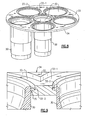
FIG. 8 is a perspective view illustrating another embodiment of a premix tube and tube plate assembly of the combustor liner cap assembly of the invention; -
FIG. 9 is a sectioned side perspective view of a part of the assembly ofFIG. 8 illustrating a first arrangement for joining the premix tubes to the tube plate; -
FIG. 10 is a sectioned side elevation view similar toFIG. 9 illustrating a second arrangement for joining the premix tubes to the tube plate; -
FIG. 11 is a sectioned side elevation view of the combustion liner cap assembly ofFIG. 9 with nozzle guides included; and -
FIG. 12 is an exploded prospective view illustrating an arrangement for retaining the nozzle guides in position on the combustor liner cap assembly ofFIG. 8 . - Referring initially to
FIG. 1 , there is depicted anindustrial gas turbine 100 of the type typically employed in land-based installations for industrial uses, such as, but not limited to, power generation. Theindustrial gas turbine 100 includes acompressor 110, a plurality ofcombustors 120, and aturbine 140. Ashaft 160 connects theturbine 140 to thecompressor 110 whereby theturbine 140 drives thecompressor 110. In power generation applications, theturbine 140 is also connected by ashaft 162 to anelectric generator 150 to drive the generator for generating electricity. The plurality ofcombustors 120 are arrayed about the gas turbine with eachcombustor 120 being connected by a transition duct to deliver hot, high velocity combustion product gases into theturbine 140. - In industrial gas turbines of this type, the
combustors 120 typically includemultiple fuel nozzles 122, generally five or six arrayed in a circular ring pattern, as illustrated inFIG. 2 . Anadditional fuel nozzle 122 may be disposed centrally within the ring of fuel nozzles and along a central axis of thecombustor 120.. Thecombustor 120 includes a longitudinally extending, generally cylindricalouter casing 124, of which only the forward section thereof is depicted inFIG. 2 , anend cover 126, acombustor liner 128, a combustorliner cap assembly 130, aflow sleeve 132 and atransition piece 134. Theend cover 126 closes the forward end of thecombustor 120 and supports the plurality offuel nozzles 122. The generallycylindrical combustor liner 128, which circumscribes and defines thecombustion chamber 125, is disposed coaxially within a generallycylindrical flow sleeve 132 that is coaxially disposed within theouter casing 124 of thecombustor 120. The combustorliner cap assembly 130 is disposed coaxially at the forward end of thecombustor liner 128 and is fixed to theouter casing 124 of thecombustor 120. Thetransition piece 134 connects at its forward end to the aft end of thecombustor liner 128 and opens at its aft inlet in fluid communication to the inlet of theturbine 140, thereby defining a flow path through which the hot combustion product gases pass from thecombustion chamber 125 into theturbine 140. - Referring now to
FIG. 2-4 , the combustorliner cap assembly 130 includes a plurality of open endedpremix tubes 30 extending longitudinally within generally cylindricalouter sleeve 32. The plurality ofpremix tubes 30 is equal in number to the plurality offuel nozzles 122 present. Eachpremix tube 30 extends between atube plate 34 at the forward end of the combustorliner cap assembly 130 and anaft end plate 36 disposed at the aft end of the combustorliner cap assembly 130. Thetube plate 34 is mounted to the forward end of theouter sleeve 32 and theaft end plate 36 is mounted to the aft end of theouter sleeve 32. A plurality of nozzle guides 50 are provided on the forward side of thetube plate 34, eachnozzle guide 50 associated with a corresponding one of thenozzle openings 35. In assembly of thecombustor 120, eachfuel nozzle 122, which extend through theend cover 126, is received into a corresponding one of the nozzle guides 50 and directed into a corresponding one of thepremix tubes 30. - The
tube plate 34 is a generally cylindrical plate having a plurality ofnozzle openings 35 passing there through, thenozzle openings 35 being equal in number to the number of premix tubes. Thefuel nozzle openings 35 may be arrayed in a circular ring about a single centrally disposedfuel nozzle opening 35, such as shown in the depicted embodiment. The forward end of eachpremix tube 30 is received within a corresponding one of thenozzle openings 35 in thetube plate 34 and, as will be discussed in further detail herein later, fixed to thetube plate 34 at a location away from the forward edge of thepremix tube 30. The aft end of eachpremix tube 30 is received in a corresponding one of plurality ofnozzle openings 37 in theaft end plate 36 in a non-fixed, sliding fit relationship to theaft end plate 36. - Referring now to
FIGs. 5-7 , there is depicted an embodiment of apremix tube 30,nozzle guide 50 andtube plate 34 assembly. For purposes of simplifying the illustration, only onepremix tube 30 is shown, but it is to be understood that there are actually sixpremix tubes 30 associated with thetube plate 34, onepremix tube 30 pernozzle opening 35. Additionally, a plurality of nozzle guides 50 are provided, with onenozzle guide 50 associated with a corresponding one of thepremix tubes 30. - As best seen in
FIGs. 6 and 7 , thepremix tube 30 is received within thenozzle opening 35 with the forward end of thepremix tube 30 extending beyond theforward face 33 of thetube plate 34. In this embodiment, the forward end of thepremix tube 30 includes a circumferentially extending, radially directedflange 40 having aface surface 42 and an undersurface 44. With the forward end of thepremix tube 30 extending beyond theforward face 33 of thetube plate 34, the undersurface 44 of theflange 40 is spaced by a distance, d, from theforward face 33 of thetube plate 34. The distance, d, should be at least about 12.7 millimeters (about 0.5 inch), and may range from about 12.7 millimeters (about 0.5 inch) to about 25.4 millimeters (about 1.0 inch). - The
nozzle guide 50 comprises an annular collar having a radially outwardly directed, circumferentially extendingbase flange 52 at a first end of the collar and an outwardly flaredguide flange 54 defining amouth 55 for guiding afuel nozzle 122 into thepremix tube 30 at an opposite end of the collar. Thebase flange 52 of thenozzle guide 50 is supported on theface surface 42 of theflange 40 on the forward end of thepremix tube 30. Thenozzle guide 50 is retained by means of a plurality of retainingmembers 60, typically three in number, spaced at intervals about the circumference of theflange 40. As illustrated inFIG. 7 , each retainingmember 60 may comprise an inverted L-shaped member having alongitudinally extending leg 62 welded at its distal end to theflange 40 on the forward end of thepremix tube 30 and having atip flange 64 extending inwardly from the proximal end of theleg 62. Thetip flange 64 extends inwardly over thebase flange 52 on thenozzle guide 50 thereby retaining thenozzle guide 50 in position on theface surface 42 of theflange 40 on the forward end of thepremix tube 30, but permitting the nozzle guide 50 a limited freedom of sliding movement relative to the associatedpremix tube 30. - Referring now to
FIGs. 8-10 , there is depicted another embodiment of a premix tube 30.andtube plate 34 assembly. For purposes of simplifying the illustration, only twopremix tubes 30 are shown, the central premix tube and one outer premix tube, but it is to be understood that there are actually sixpremix tubes 30 associated with thetube plate 34, onepremix tube 30 pernozzle opening 35. Thetube plate 30, in addition to having a plurality of fuel nozzle openings, includes a plurality of first countersunk surfaces 33-1 in theforward face 33 and a plurality of second countersunk surfaces 33-2 in theforward face 33. Each of the first countersunk surfaces 33-1 surrounds a corresponding one of the plurality offuel nozzle openings 35. Each of the second countersunk surfaces 33-2 is formed within a corresponding one of the plurality of first countersunk surfaces 33-1 and surrounds a corresponding one of the plurality offuel nozzle openings 35. - As best seen in
Figs. 9 and10 , eachpremix tube 30 is received within thenozzle opening 35 with the forward end of the premix tube extending beyond the second countersunk surface 33-2 and the forward edge of the forward end of the premix tube being substantially flush with the first countersunk surface 33-1. Eachpremix tube 30 is brazed to thetube plate 34, the braze joint 70 extending along theinterface 70 of thepremix tube 30 and thetube plate 34 about the portion of thenozzle opening 35 extending between theaft face 39 of thetube plate 34 and the second countersink surface 33-2. The second countersunk surface 33-2 may be parallel to the first countersunk surface 33-1, such as, for example, as depicted inFIG. 9 , or may be formed as a chamfer extending downwardly at an angle from the first countersunk surface 33-1 to intersect thenozzle opening 35, such as, for example, depicted inFIG. 10 . Eachpremix tube 30 may also include a radially outward extendinglip 80 set back aftwardly from the forward edge of the forward end of thepremix tube 30, as illustrated inFIG. 10 . When thepremix tube 30 is received in thenozzle opening 35, theforward face 82 of thelip 80 abuts theaft face 39 of thetube plate 34. With thelip 80, the braze joint 70 between thepremix tube 30 and thetube plate 34 extends into the interface between theforward face 82 of thelip 80 and the aft face 39 of thetube plate 34. Additionally, thelips 80 may be located relative to the forward edge of the forward end of thepremix tube 30 so as to ensure that when thepremix tube 30 is received in thenozzle opening 35 with theforward face 82 of thelip 80 abutting the aft face 39 of thetube plate 34, the forward edge of the forward end of thepremix tube 30 is positioned flush with the first countersunk surface 33-1 in theforward face 33 of thetube plate 34. - As with the embodiment depicted in
FIGs. 5-7 and described previously, a plurality of nozzle guides 50 are provided on the premix tube and tube plate assembly depicted inFIGs. 8-10 , with onenozzle guide 50 associated with a corresponding one of thepremix tubes 30. Referring now toFIGs.11 and12 , thebase flange 52 of thenozzle guide 50 is supported in floating relationship on the first countersunk 33-1. That is, the outside diameter of the first countersunk surface 33-1 is slightly larger than the outside diameter of thebase flange 52 of thenozzle guide 50 thereby permitting the nozzle guide 50 a limited freedom of sliding movement relative to the associatedpremix tube 30. Aretainer plate 90 is secured to theforward face 33 of thetube plate 34, such as, for example, bybolts 92 screwed into threaded holes in thetube plate 34, to hold thebase flanges 52 of the nozzle guides 50 in position. As illustrated inFIG. 12 , theretainer plate 90 may be comprised of a plurality ofplate sectors 94, oneplate sector 94 positioned and secured to thetube plate 34 between a corresponding pair of nozzle guides 50. Each sector plate overlaps a portion of thebase flange 52 of each of the nozzle guides 50 supported on the first countersunk surface 33-1 of the correspondingouter nozzle openings 35, as well as a portion of thebase flange 52 of the singlecentral nozzle guide 50. - The terminology used herein is for the purpose of description, not limitation. Specific structural and functional details disclosed herein are not to be interpreted as limiting, but merely as basis for teaching one skilled in the art to employ the present invention. Those skilled in the art will also recognize the equivalents that may be substituted for elements described with reference to the exemplary embodiments disclosed herein without departing from the scope of the present invention.
- While the present invention has been particularly shown and described with reference to the exemplary embodiments as illustrated in the drawing, it will be recognized by those skilled in the art that various modifications may be made without departing from the spirit and scope of the invention. Therefore, it is intended that the present disclosure not be limited to the particular embodiment(s) disclosed as, but that the disclosure will include all embodiments falling within the scope of the appended claims.
Claims (15)
- A combustor liner cap assembly for use in a multiple fuel nozzle combustor of a gas turbine comprising:a tube plate having a plurality of fuel nozzle openings;a plurality of open ended premix tubes extending from the tube plate, each premix tube having a forward end having a forward edge, the forward end received in a corresponding one of the fuel nozzle openings and extending at least to a forward face of the tube plate, each premix tube fixed to the tube plate away of the forward edge of the forward end of the premix tube.
- The combustor liner cap assembly as recited in claim 1 wherein each premix tube is metallurgically bonded to the tube plate aft of the forward edge of the forward end of the premix tube.
- The combustor liner cap assembly as recited in claim 2 wherein each premix tube is welded or brazed to the tube plate.
- The combustor liner cap assembly as recited in claim 1 further comprising:a substantially cylindrical, longitudinally extending sleeve having a forward end and an aft end, the tube plate fixed to the forward end of the sleeve; andan aft plate fixed to the aft end of the sleeve and having a plurality of fuel nozzle openings, each fuel nozzle opening receiving an aft end of a corresponding one of the plurality of premix tubes in a sliding relationship.
- A combustor liner cap assembly as claimed in claim 1, further comprising:a substantially cylindrical, longitudinally extending sleeve having a forward end and an aft end;wherein the tube plate is fixed to the forward end of the sleeve; andthe plurality of open ended premix tubes extend aft from the tube plate, the forward end of each being received in a corresponding one of the fuel nozzle openings and extending beyond a forward face of the tube plate, each premix tube fixed to the tube plate aft of the forward edge of the forward end of the premix tube.
- The combustor liner cap assembly as recited in claim 5 wherein each premix tube includes a radial flange extending about the forward end of the premix tube, the radial flange having a face surface flush with the face surface of the premix tube and an under surface.
- The combustor liner cap assembly as recited in claim 6 wherein the forward end of the each premix tube extends beyond the forward face of the tube plate by a distance of at least about 12.7 millimeters (about 0.5 inch), preferably by a distance ranging from about 12.7 millimeters (about 0.5 inch) to about 25.4 millimeters (about 1.0 inch), as measured from the under surface of the radial flange of the premix tube to the forward face of the tube plate.
- The combustor liner cap assembly as recited in claim 7 wherein each premix tube is welded to the tube plate.
- The combustor liner cap assembly as recited in claim 6 further comprising a plurality of open-ended nozzle guides, each nozzle guide having a first end having a radial flange, the first end of each nozzle guide assembled in floating relationship in abutment with a corresponding one of the plurality of premix tubes.
- The combustor liner cap assembly as recited in claim 9 further comprising a plurality of retaining members associated with each premix tube and nozzle guide assembly, each retaining member having a longitudinally extending leg mounted to the radial flange on the forward end of the premix tube and a tip flange extending radially over the radial flange of nozzle guide assembly.
- A combustor liner cap assembly as claimed in claim 1, further comprising:a substantially cylindrical, longitudinally extending sleeve having a forward end and an aft end;wherein the tube plate is fixed to the forward end of the sleeve, said tube plate having a forward face, said plurality of fuel nozzle openings, a plurality of first countersunk surfaces in the forward face, each first countersunk surface surrounding a corresponding one of the plurality of fuel nozzle openings, and a plurality of second countersunk surfaces, each second countersunk surface formed within a corresponding one of the plurality of first countersunk surfaces and surrounding a corresponding one of the plurality of fuel nozzle openings; andthe plurality of open ended premix tubes extend aft from the tube plate, the forward end of each being received in a corresponding one of the fuel nozzle openings and disposed with the forward edge flush with the first countersunk surface in forward face of the tube plate, each premix tube brazed to the tube plate along an interface of the premix tube and the tube plate between an aft surface of the tube plate and the second countersink surface.
- The combustor linear cap assembly as recited in claim 11 wherein each of the plurality of second countersunk surfaces is formed as a chamfer relative to a corresponding one of the plurality of the first countersunk surfaces.
- The combustor linear cap assembly as recited in claim 11 wherein each premix tube includes a radially outwardly directed circumferentially extending lip located aft of the forward end of the premix tube, the lip having a face surface abutting the aft surface of the tube plate.
- The combustor liner cap assembly as recited in claim 11 further comprising a plurality of open-ended nozzle guides, each nozzle guide having a first end having a radial base flange, the first end of each nozzle guide assembled in floating relationship in abutment with a corresponding one of the plurality of first countersunk surfaces.
- The combustor liner cap assembly as recited in claim 14 further comprising a plurality of retaining plate sectors secured to tube plate, each retaining plate sector disposed between a corresponding pair of nozzle guides and overlaps a portion of the base flange of each of the corresponding pair of nozzle guides.
Applications Claiming Priority (1)
| Application Number | Priority Date | Filing Date | Title |
|---|---|---|---|
| US12/822,607 US8572979B2 (en) | 2010-06-24 | 2010-06-24 | Gas turbine combustor liner cap assembly |
Publications (2)
| Publication Number | Publication Date |
|---|---|
| EP2400219A2 true EP2400219A2 (en) | 2011-12-28 |
| EP2400219A3 EP2400219A3 (en) | 2015-07-29 |
Family
ID=44675963
Family Applications (1)
| Application Number | Title | Priority Date | Filing Date |
|---|---|---|---|
| EP11250599.5A Withdrawn EP2400219A3 (en) | 2010-06-24 | 2011-06-20 | Gas turbine combustor liner cap assembly |
Country Status (2)
| Country | Link |
|---|---|
| US (1) | US8572979B2 (en) |
| EP (1) | EP2400219A3 (en) |
Cited By (1)
| Publication number | Priority date | Publication date | Assignee | Title |
|---|---|---|---|---|
| CN109210571A (en) * | 2017-07-04 | 2019-01-15 | 斗山重工业株式会社 | Fuel nozzle assembly and burner and gas turbine including it |
Families Citing this family (20)
| Publication number | Priority date | Publication date | Assignee | Title |
|---|---|---|---|---|
| US8966907B2 (en) * | 2012-04-16 | 2015-03-03 | General Electric Company | Turbine combustor system having aerodynamic feed cap |
| US9010122B2 (en) | 2012-07-27 | 2015-04-21 | United Technologies Corporation | Turbine engine combustor and stator vane assembly |
| US9175855B2 (en) * | 2012-10-29 | 2015-11-03 | General Electric Company | Combustion nozzle with floating aft plate |
| US9759425B2 (en) | 2013-03-12 | 2017-09-12 | General Electric Company | System and method having multi-tube fuel nozzle with multiple fuel injectors |
| US20140338340A1 (en) * | 2013-03-12 | 2014-11-20 | General Electric Company | System and method for tube level air flow conditioning |
| US9366439B2 (en) | 2013-03-12 | 2016-06-14 | General Electric Company | Combustor end cover with fuel plenums |
| US9347668B2 (en) | 2013-03-12 | 2016-05-24 | General Electric Company | End cover configuration and assembly |
| US9651259B2 (en) | 2013-03-12 | 2017-05-16 | General Electric Company | Multi-injector micromixing system |
| US9528444B2 (en) | 2013-03-12 | 2016-12-27 | General Electric Company | System having multi-tube fuel nozzle with floating arrangement of mixing tubes |
| US9650959B2 (en) | 2013-03-12 | 2017-05-16 | General Electric Company | Fuel-air mixing system with mixing chambers of various lengths for gas turbine system |
| US9671112B2 (en) | 2013-03-12 | 2017-06-06 | General Electric Company | Air diffuser for a head end of a combustor |
| US9534787B2 (en) | 2013-03-12 | 2017-01-03 | General Electric Company | Micromixing cap assembly |
| US9765973B2 (en) * | 2013-03-12 | 2017-09-19 | General Electric Company | System and method for tube level air flow conditioning |
| US9400114B2 (en) * | 2013-03-18 | 2016-07-26 | General Electric Company | Combustor support assembly for mounting a combustion module of a gas turbine |
| WO2015057272A1 (en) * | 2013-10-18 | 2015-04-23 | United Technologies Corporation | Combustor wall having cooling element(s) within a cooling cavity |
| DE102013223258A1 (en) * | 2013-11-14 | 2015-06-03 | Rolls-Royce Deutschland Ltd & Co Kg | Combustion heat shield element of a gas turbine |
| US10429073B2 (en) | 2015-12-21 | 2019-10-01 | General Electric Company | Combustor cap module and retention system therefor |
| JP6863718B2 (en) * | 2016-11-21 | 2021-04-21 | 三菱パワー株式会社 | Gas turbine combustor |
| JP7270517B2 (en) * | 2019-10-01 | 2023-05-10 | 三菱重工業株式会社 | gas turbine combustor |
| JP2021055971A (en) * | 2019-10-01 | 2021-04-08 | 三菱パワー株式会社 | Gas turbine combustor |
Family Cites Families (12)
| Publication number | Priority date | Publication date | Assignee | Title |
|---|---|---|---|---|
| US4982570A (en) | 1986-11-25 | 1991-01-08 | General Electric Company | Premixed pilot nozzle for dry low Nox combustor |
| US5259184A (en) | 1992-03-30 | 1993-11-09 | General Electric Company | Dry low NOx single stage dual mode combustor construction for a gas turbine |
| US5274991A (en) | 1992-03-30 | 1994-01-04 | General Electric Company | Dry low NOx multi-nozzle combustion liner cap assembly |
| DE69306025T2 (en) | 1992-03-30 | 1997-05-28 | Gen Electric | Construction of a combustion chamber dome |
| US5685693A (en) | 1995-03-31 | 1997-11-11 | General Electric Co. | Removable inner turbine shell with bucket tip clearance control |
| US5722230A (en) | 1995-08-08 | 1998-03-03 | General Electric Co. | Center burner in a multi-burner combustor |
| US6298667B1 (en) * | 2000-06-22 | 2001-10-09 | General Electric Company | Modular combustor dome |
| US6438959B1 (en) | 2000-12-28 | 2002-08-27 | General Electric Company | Combustion cap with integral air diffuser and related method |
| US6467272B1 (en) | 2001-06-25 | 2002-10-22 | Power Systems Mfg, Llc | Means for wear reduction in a gas turbine combustor |
| US6581386B2 (en) * | 2001-09-29 | 2003-06-24 | General Electric Company | Threaded combustor baffle |
| US6923002B2 (en) | 2003-08-28 | 2005-08-02 | General Electric Company | Combustion liner cap assembly for combustion dynamics reduction |
| US8438853B2 (en) * | 2008-01-29 | 2013-05-14 | Alstom Technology Ltd. | Combustor end cap assembly |
-
2010
- 2010-06-24 US US12/822,607 patent/US8572979B2/en active Active
-
2011
- 2011-06-20 EP EP11250599.5A patent/EP2400219A3/en not_active Withdrawn
Non-Patent Citations (1)
| Title |
|---|
| None |
Cited By (2)
| Publication number | Priority date | Publication date | Assignee | Title |
|---|---|---|---|---|
| CN109210571A (en) * | 2017-07-04 | 2019-01-15 | 斗山重工业株式会社 | Fuel nozzle assembly and burner and gas turbine including it |
| CN109210571B (en) * | 2017-07-04 | 2020-07-24 | 斗山重工业株式会社 | Fuel nozzle assembly, combustor including same, and gas turbine |
Also Published As
| Publication number | Publication date |
|---|---|
| US8572979B2 (en) | 2013-11-05 |
| US20110314823A1 (en) | 2011-12-29 |
| EP2400219A3 (en) | 2015-07-29 |
Similar Documents
| Publication | Publication Date | Title |
|---|---|---|
| EP2400219A2 (en) | Gas turbine combustor liner cap assembly | |
| EP2899466B1 (en) | Method for repairing a bundled tube fuel injector | |
| EP2578944B1 (en) | Combustor and method for supplying fuel to a combustor | |
| US8534040B2 (en) | Apparatus and method for igniting a combustor | |
| JP6840513B2 (en) | Focused tube fuel nozzle assembly with liquid fuel function | |
| EP2208933B1 (en) | Combustor assembly and cap for a turbine engine | |
| EP3220047B1 (en) | Gas turbine flow sleeve mounting | |
| EP2851619B1 (en) | Dual-fuel burning gas turbine combustor | |
| CN101943407B (en) | Fuel nozzle assembly for gas-turbine unit | |
| EP2584268A2 (en) | Flashback resistant tubes in tube LLI design | |
| US9423134B2 (en) | Bundled tube fuel injector with a multi-configuration tube tip | |
| JP2005098681A (en) | Combustor dome assembly for gas turbine engine with freefloating swirler | |
| US9127551B2 (en) | Turbine combustion system cooling scoop | |
| EP3430315A1 (en) | Gas turbine annular combustor arrangement | |
| JP2004085189A (en) | Combustor dome for gas turbine engine | |
| EP2578940A2 (en) | Combustor and method for supplying flow to a combustor | |
| CN108626746A (en) | Fuel nozzle for gas-turbine unit | |
| EP3220049A1 (en) | Gas turbine combustor having liner cooling guide vanes | |
| EP2592349A2 (en) | Combustor and method for supplying fuel to a combustor | |
| EP3339609A1 (en) | Mounting assembly for gas turbine engine fluid conduit | |
| US20180209647A1 (en) | Fuel Nozzle Assembly with Fuel Purge | |
| CN109140503B (en) | Dual fuel nozzle with gaseous and liquid fuel capability | |
| EP4067746B1 (en) | Combustor having a wake energizer | |
| JP7303011B2 (en) | Combustor and gas turbine | |
| EP4202304A1 (en) | Fuel nozzle and swirler |
Legal Events
| Date | Code | Title | Description |
|---|---|---|---|
| AK | Designated contracting states |
Kind code of ref document: A2 Designated state(s): AL AT BE BG CH CY CZ DE DK EE ES FI FR GB GR HR HU IE IS IT LI LT LU LV MC MK MT NL NO PL PT RO RS SE SI SK SM TR |
|
| AX | Request for extension of the european patent |
Extension state: BA ME |
|
| PUAI | Public reference made under article 153(3) epc to a published international application that has entered the european phase |
Free format text: ORIGINAL CODE: 0009012 |
|
| RAP1 | Party data changed (applicant data changed or rights of an application transferred) |
Owner name: PW POWER SYSTEMS, INC. |
|
| PUAL | Search report despatched |
Free format text: ORIGINAL CODE: 0009013 |
|
| AK | Designated contracting states |
Kind code of ref document: A3 Designated state(s): AL AT BE BG CH CY CZ DE DK EE ES FI FR GB GR HR HU IE IS IT LI LT LU LV MC MK MT NL NO PL PT RO RS SE SI SK SM TR |
|
| AX | Request for extension of the european patent |
Extension state: BA ME |
|
| RIC1 | Information provided on ipc code assigned before grant |
Ipc: F23R 3/00 20060101AFI20150622BHEP |
|
| 17P | Request for examination filed |
Effective date: 20151208 |
|
| RBV | Designated contracting states (corrected) |
Designated state(s): AL AT BE BG CH CY CZ DE DK EE ES FI FR GB GR HR HU IE IS IT LI LT LU LV MC MK MT NL NO PL PT RO RS SE SI SK SM TR |
|
| 17Q | First examination report despatched |
Effective date: 20180419 |
|
| RAP1 | Party data changed (applicant data changed or rights of an application transferred) |
Owner name: PW POWER SYSTEMS LLC |
|
| RAP1 | Party data changed (applicant data changed or rights of an application transferred) |
Owner name: MECHANICAL DYNAMICS & ANALYSIS LLC |
|
| STAA | Information on the status of an ep patent application or granted ep patent |
Free format text: STATUS: THE APPLICATION IS DEEMED TO BE WITHDRAWN |
|
| 18D | Application deemed to be withdrawn |
Effective date: 20180830 |