EP2400210A9 - Système d'éclairage - Google Patents
Système d'éclairage Download PDFInfo
- Publication number
- EP2400210A9 EP2400210A9 EP11170802.0A EP11170802A EP2400210A9 EP 2400210 A9 EP2400210 A9 EP 2400210A9 EP 11170802 A EP11170802 A EP 11170802A EP 2400210 A9 EP2400210 A9 EP 2400210A9
- Authority
- EP
- European Patent Office
- Prior art keywords
- lighting unit
- track member
- track
- lighting
- arms
- Prior art date
- Legal status (The legal status is an assumption and is not a legal conclusion. Google has not performed a legal analysis and makes no representation as to the accuracy of the status listed.)
- Granted
Links
Images


Classifications
-
- F—MECHANICAL ENGINEERING; LIGHTING; HEATING; WEAPONS; BLASTING
- F21—LIGHTING
- F21V—FUNCTIONAL FEATURES OR DETAILS OF LIGHTING DEVICES OR SYSTEMS THEREOF; STRUCTURAL COMBINATIONS OF LIGHTING DEVICES WITH OTHER ARTICLES, NOT OTHERWISE PROVIDED FOR
- F21V21/00—Supporting, suspending, or attaching arrangements for lighting devices; Hand grips
- F21V21/02—Wall, ceiling, or floor bases; Fixing pendants or arms to the bases
- F21V21/025—Elongated bases having a U-shaped cross section
-
- F—MECHANICAL ENGINEERING; LIGHTING; HEATING; WEAPONS; BLASTING
- F21—LIGHTING
- F21V—FUNCTIONAL FEATURES OR DETAILS OF LIGHTING DEVICES OR SYSTEMS THEREOF; STRUCTURAL COMBINATIONS OF LIGHTING DEVICES WITH OTHER ARTICLES, NOT OTHERWISE PROVIDED FOR
- F21V21/00—Supporting, suspending, or attaching arrangements for lighting devices; Hand grips
- F21V21/14—Adjustable mountings
- F21V21/30—Pivoted housings or frames
-
- F—MECHANICAL ENGINEERING; LIGHTING; HEATING; WEAPONS; BLASTING
- F21—LIGHTING
- F21Y—INDEXING SCHEME ASSOCIATED WITH SUBCLASSES F21K, F21L, F21S and F21V, RELATING TO THE FORM OR THE KIND OF THE LIGHT SOURCES OR OF THE COLOUR OF THE LIGHT EMITTED
- F21Y2103/00—Elongate light sources, e.g. fluorescent tubes
- F21Y2103/10—Elongate light sources, e.g. fluorescent tubes comprising a linear array of point-like light-generating elements
-
- F—MECHANICAL ENGINEERING; LIGHTING; HEATING; WEAPONS; BLASTING
- F21—LIGHTING
- F21Y—INDEXING SCHEME ASSOCIATED WITH SUBCLASSES F21K, F21L, F21S and F21V, RELATING TO THE FORM OR THE KIND OF THE LIGHT SOURCES OR OF THE COLOUR OF THE LIGHT EMITTED
- F21Y2115/00—Light-generating elements of semiconductor light sources
- F21Y2115/10—Light-emitting diodes [LED]
Definitions
- the following relates to the illumination arts, lighting arts, and related arts.
- a wide variety of indirect lighting and architectural lighting fixtures are known.
- One particular area of indirect lighting is often referred to as cove lighting.
- an upwardly open channel is built along a wall near the ceiling, for example.
- the wall may be a side wall of the room, a sidewall of a recess in the ceiling, a side surface of a beam, or the like.
- Lighting units are mounted within the channels so that the emitted light escapes generally upward to directly light the wall and ceiling above and, indirectly, an interior of the room and its contents.
- Such channels are often built with conventional building techniques involving framing, sheetrocking/plastering, etc.
- Cove lighting can also be installed in cabinets or display cases, or virtually anywhere such lighting is desired.
- a track is first secured to a mounting surface, and then one or more lighting units are installed to the track. Before or after installation of the lighting units to the track, the lighting unit can be wired or otherwise connected to a power source.
- the lighting units can be aimed to achieve uniform distribution of the light along a wall or ceiling, or to focus on a specific architectural feature, etc.
- One manner in which prior art lighting units can be aimed is by installing a track with a particular angular offset.
- a lighting system might include a variety of tracks having various angular offsets, for example, 90 degrees, 60 degrees, 45 degrees 30 degrees, etc.
- the installer can select and install the track with the appropriate offset to achieve the desired angular position of the lighting unit.
- Another prior art approach has been to rotatably support the lighting unit with a base assembly that can be mounted to the track. Once the base assembly is secured to the track, the lighting unit can be rotated relative to the base assembly to aim the light.
- a lighting system comprises a track member including a base for mounting the track to a surface, the track member having first and second arms extending from the base in a common direction and defining therebetween a channel, and a lighting unit having a housing adapted to be received in the channel of the track member.
- the housing and at least one of the arms of the track member have rotationally interfering members for restricting rotation of the lighting unit relative to the track member when the at least one arm is in a first position, said at least one arm being moveable to a second position whereat the lighting unit can be rotated relative to the track member.
- the rotationally interfering members can include at least one mating recess or protrusion associated with the at least one arm, and at least one mating recess or protrusion associated with the lighting unit.
- the housing may be generally tubular.
- the housing is generally tubular and the at least one mating recess or protrusion associated with the track member and lighting unit can include axially extending ribs or grooves provided on the exterior surface of the housing of the lighting unit and the interior surface of the at least one arm.
- the at least one arm can be adapted to pivot from the first position to the second position when a threshold rotational force is applied to the lighting unit.
- the housing of the lighting unit is generally tubular and the first and second arms of the track member are configured to closely receive the lighting unit on opposing sides thereof.
- the housing is generally tubular and the lighting unit can include a non-circular axially extending protrusion or recess for cooperating with a tool for applying rotational force to the lighting unit.
- the angular position of the lighting unit can be adjusted in increments corresponding to the dimensions of the mating recesses and protrusions.
- the track member can be made of a resilient material, for example, a plastic material.
- the first and second arms are mirror images of each other.
- the first arm extends laterally away from a longitudinal axis of the base a greater distance than the second arm extends laterally away from the longitudinal axis of the base such that the first and second arms are offset.
- the lighting system may further comprising a track retainer, wherein the track retainer is interposed between the track member and the lighting unit.
- the track retainer is secured to a rail of the track member.
- the track member includes a rail extending along the base for cooperating with at least one flange on the track retainer for releasable securing the track retainer to the track member.
- a track member for rotationally supporting a lighting unit comprising: a base for mounting the track to a surface; first and second arms extending from the base in a common direction and defining therebetween a channel for receiving the lighting unit; wherein at least one of the arms of the track member has a rotationally interfering member for cooperating with a corresponding rotationally interfering member associated with the lighting unit for restricting rotation of the lighting unit relative to the track member when the lighting unit is received in the channel.
- the first and second arms are adapted to pivot between a first position whereat rotation of the lighting unit is restricted, to a second position permitting rotation of the lighting unit relative to the track member.
- the track member further comprises a raised rail extending along a longitudinal axis of the base.
- the rotationally interfering member of the track member can include at least one mating recess or protrusion associated with the at least one arm for cooperating with a corresponding at least one mating recess or protrusion associated with the lighting unit.
- the at least one mating recess or protrusion associated with the track member can include ribs or grooves provided on the interior surface of the at least one arm.
- the first and second arms of the track member are configured to closely receive the lighting unit on opposing sides thereof.
- the track member can be made of a resilient material, for example, a plastic material.
- the first and second arms are mirror images of each other.
- the first arm extends laterally away from a longitudinal axis of the base a greater distance than the second arm extends laterally away from the longitudinal axis of the base such that the first and second arms are offset.
- the invention may take form in various components and arrangements of components, and in various process operations and arrangements of process operations.
- the drawings are only for purposes of illustrating embodiments and are not to be construed as limiting the invention.
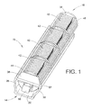
- FIGURE 1 is a perspective view of an exemplary lighting system in a first angular position in accordance with the present disclosure.
- FIGURE 2 is an end view of the lightning assembly of FIGURE 1 .
- FIGURE 3 is a perspective view of the lighting assembly if FIGURE 1 rotated to a second angular position
- FIGURE 4 is a perspective view of an exemplary track in accordance with the present disclosure.
- FIGURE 5 is an end view of another exemplary track in accordance with the present disclosure.
- FIGURE 6 is a perspective view of an exemplary track retainer in accordance with the present disclosure.
- FIGURE 7 is an end view of the track retainer of FIGURE 6 .
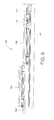
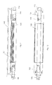
- FIGURE 8 is a side elevational view of another exemplary lighting assembly.
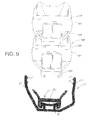
- FIGURE 9 is an end view of the lighting assembly of FIGURE 8 in a partially assembled state.
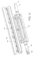
- FIGURE 10 is an exploded view of an exemplary lighting unit.
- FIGURE 11 is a side elevational view of the lighting unit of FIGURE 10 .
- FIGURE 12 is a bottom view the lighting unit of FIGURE 10 .
- FIGURE 13 is an end view of the lighting unit of FIGURE 10 .
- the system 10 generally includes a track member 14 and a lighting unit 18 supported by the track member 14.
- the track member 14 includes an elongate base 22 for mounting the track member 14 to a surface, such as a wall, frame, etc.
- the base 22 can include a plurality of holes 24 (see FIGURE 4 ) for installing fasteners or the like.
- a pair of arms 26 and 30 extend from the base 22 in a common direction and define therebetween a channel 34 for receiving the lighting unit 18.
- the arms 26 and 30 may include a curved portion thereof that is generally shaped to match an outer surface of the lighting unit 18 such that the lighting unit 18 is closely received within the channel 34.
- arms 26 and 30 are configured to pivot about respective pivot points P.
- the track member 14 can be made as a unitary piece as illustrated, or may be assembled from individual components.
- the lighting unit 18 includes a housing 38 for supporting lightning elements 42, which may be LEDs or other suitable lighting elements, and other electronic components that may be associated therewith.
- a clear or otherwise translucent lens 44 can be provided over the lighting elements 42.
- the lens can contain different optics to generate different viewing angles, and could be modular so that for different viewing angles of lens used on the LED, the track can be mounted at different distances from the wall and adjusted for rotation for the most uniformity on the wall or surface. As will be appreciated, however, any suitable type of lighting element can be used.
- the housing 38 is generally tubular (although other shapes are contemplated including oblong, for example) and includes a plurality of axially extending recesses in the form of grooves 48 provided on the exterior surface of the housing around a major portion of its circumference.
- the grooves 48 are adapted to cooperate with correspondingly shaped protrusions in the form of axially extending ridges or ribs 52 on the interior surface of arms 26 and 30 for restricting rotation of the lighting unit 18 relative to the track member 14.
- These rotationally interfering members not only restrict rotation of the lighting unit when the arms 26 and 30 are in the position illustrated in FIGURES 1 and 2 , but also cooperate to retain the lighting unit 18 in the track member 14. That is, when the ridges or ribs 52 are received within the grooves 48, the lighting unit 18 is secured to the track and rotation of the lighting unit 18 relative to the track member 14 is restricted.
- the track is first secured to surface.
- the lighting unit 18 is then inserted into the channel 34 in the track member 14.
- the arms 26 and 30 are outwardly displaced to accommodate the lighting unit 18 in the channel 34.
- the arms 26 and 30 are dimensioned such that this outward displacement occurs as a result of the lighting unit 10 being urged into place, and no other action is required by an installer to seat the lighting unit 18 in the track member 14.
- the arms 26 and 30 and/or base 22 can be made of a material, such as plastic, that provides some resiliency to the arms 26 and 30 such that after the outward displacement during installation or, as will be described below, angular adjustment of the lighting unit 18, the arms 26 and 30 "spring" back to the position shown in FIGURES 1 and 2 .
- This resiliency can be achieved not only through the selection of a suitable material, but also through the shape of the arms 26 and 30.
- the arms 26 and 30 are adapted to pivot about respective pivots points P when deflected outwardly.
- a track retainer can be installed for providing additional retention for certain installations, such as a hanging installation.
- a rotational force is applied to the housing 38.
- This rotational force can be applied by hand or via a suitable tool designed to engage the housing 38.
- a non-circular protrusion in the form of a rectangular head 56 extends from the housing 38 for engagement with a suitable tool, such as a wrench, for applying rotational force to the housing 38.
- a suitable tool such as a wrench
- the rectangular head 56 could also be grasped by a user's fingers and rotated.
- the lighting system 10 is shown in a rotated position wherein the lighting unit 18 has been rotated within the track member 14 as compared to the position of FIGURES 1 and 2 .
- the angular position of the lighting unit 18 can be adjusted in increments corresponding to the dimensions and/or spacing of the cooperating grooves 48 and ridges or ribs 52.
- more grooves 48 can be provided on the housing 38.
- fewer grooves 48 may be provided.
- the grooves 48 could be spaced apart at particular intervals corresponding to specific angles. For example, grooves corresponding to 30 degrees, 45 degrees, 60 degrees, etc. could be provided. To indicate these grooves as corresponding to particular angles, the grooves could be shaped differently than grooves corresponding to other angular positions in between.
- markings could be provided on the housing 38 to indicate the angle to which a given groove corresponds.
- the threshold rotational force needed to displace the arms 26 and 30 outwardly in order to rotate the lighting unit 18 can be, at least in part, a property of the material of the arms 26 and 30.
- the shape or profile of the grooves 48 and ridges or ribs 52 can also effect the threshold force. For example, a steeper profile may require increased force whereas a more gradual profile may require less force. To this end, it will be understood that a desired threshold force can be achieved by altering such design parameters.
- the grooves 48 and/or ridges or ribs 52 may not be continuous along their axial lengths such that a given cooperating groove/ridge or ribs may not be engaged along its entire axial length. Such arrangement would tend to decrease the threshold force.
- a suitable locking mechanism could be provided for preventing angular adjustment or removal of the lighting assembly from the track member.
- Such locking mechanism could take the form of a clip that connects the arms 26 and 30 thereby preventing outward displacement of the arms 26 and 30 until such time as the clip is removed.
- the track member 60 includes an elongate base 62 for mounting the track member 60 to a surface, such as a wall, frame, etc., and a pair of arms 66 and 70 extending from the base 62 in a common direction and defining therebetween a channel 74 for receiving a lighting unit.
- the arms 66 and 70 are asymmetric, with arm 66 extending laterally away from the base 62 a greater distance than arm 70. This offset arrangement of the arms 66 and 70 may tend to direct a lighting unit, when installed therein, towards a certain angular orientation.
- track member 60 can be used in certain installations having limited space and/or obstructions adjacent the mounting surface.
- Track member 60 also has a rail 75 spaced from the elongated base 62 and extending in a common direction therewith.
- Rail 75 has an upper concave surface, and first and second flanges 76 and 78.
- the flanges 76 and 78 are adapted to cooperate with corresponding flanges on a track retainer to provide additional retention to secure an associated lighting unit to the track member 60.
- an exemplary track retainer 80 is shown for use in conjunction with a track member (such as track member 60 described above) for providing additional retaining force to a lighting unit.
- the track retainer 80 may have particular application in hanging installations, wherein it may be desirable to provide an enhanced level of retention of the lighting unit in the track member.
- the track retainer 80 includes an elongated base 82 defining a generally planar surface, and front and rear retention members in the form of left and right flying tabs 84 and 86 extending from the base 82.
- Each pair of tabs 84 and 86 is adapted to cradle a portion of a lighting unit.
- the tabs 84 and 86 can be configured to engage and/or interlock with a corresponding surface of an associated lighting unit.
- First and second flanges 90 and 92 extend from the base 82 opposite the tabs 34 and 86, and are adapted to engage the flanges 76 and 78 of the track member 60, for example.
- FIGURES 8 and 9 another exemplary lighting system is illustrated and generally identified by reference numeral 100.
- a single track member 104 is designed to accommodate a plurality of lighting units 108.
- the track member 104 is identical to the track member 60 described previously and includes an elongated base 110, first and second offset arms 112 and 114 extending from said base, and a rail 116.
- the lighting units 108 are secured to the track 104 in a similar manner as the embodiment of FIGURES 1-4 , and further track retainers 120 are installed on rail 116 and act to further secure the lighting units 108 to the track member 104.
- each track retainer 120 is received on rail 116 between adjacent lighting units 108.
- the track retainers 120 are positioned between respective lighting units 108 and then said lighting units are installed to the track 104 with the flying arms of the track retainer cooperating with corresponding tabs on the housing of the lighting units 108.
- the arms 112 and 114 of the track 104 also engage and secure the lighting units 108 to the track 104, in a similar manner to that previously described.
- the lighting unit 108 includes a base housing 120, and upper housing 121, and first and second wire harnesses 122 and 124 including connectors 126 and 128.
- a heat sink 130 partially surrounds an LED circuit board 132.
- a lens 140 covers the LED circuit board 132.
- an exterior surface of the upper housing 121 includes a plurality of grooves 142 for cooperating with mating protrusions 144 on the arms 112 and 114 of the track 104 for restricting rotation of the lighting unit 108 and/or securing the lighting unit 108 to the track 104.
- the present disclosure provides a lighting system that facilitates simple installation and one-step angular adjustment.
- the system provides an angular adjustment mechanism without moving parts thus making the system easy to manufacture, install and adjust.
- any suitable number of lighting units can be installed in a given track member, and each individual lighting unit can be adjusted to a desired angular position without removal from the track member.
Landscapes
- Engineering & Computer Science (AREA)
- General Engineering & Computer Science (AREA)
- Non-Portable Lighting Devices Or Systems Thereof (AREA)
- Arrangement Of Elements, Cooling, Sealing, Or The Like Of Lighting Devices (AREA)
- Fastening Of Light Sources Or Lamp Holders (AREA)
Applications Claiming Priority (2)
| Application Number | Priority Date | Filing Date | Title |
|---|---|---|---|
| US35811310P | 2010-06-24 | 2010-06-24 | |
| US13/154,102 US8888335B2 (en) | 2010-06-24 | 2011-06-06 | Lighting system |
Publications (4)
| Publication Number | Publication Date |
|---|---|
| EP2400210A2 EP2400210A2 (fr) | 2011-12-28 |
| EP2400210A3 EP2400210A3 (fr) | 2013-11-20 |
| EP2400210A9 true EP2400210A9 (fr) | 2015-10-14 |
| EP2400210B1 EP2400210B1 (fr) | 2016-07-20 |
Family
ID=44680920
Family Applications (1)
| Application Number | Title | Priority Date | Filing Date |
|---|---|---|---|
| EP11170802.0A Not-in-force EP2400210B1 (fr) | 2010-06-24 | 2011-06-21 | Système d'éclairage |
Country Status (3)
| Country | Link |
|---|---|
| US (1) | US8888335B2 (fr) |
| EP (1) | EP2400210B1 (fr) |
| CN (1) | CN102418858B (fr) |
Families Citing this family (23)
| Publication number | Priority date | Publication date | Assignee | Title |
|---|---|---|---|---|
| TWI412692B (zh) * | 2010-09-21 | 2013-10-21 | Harvatek Corp | 可透過旋轉方式來調整光投射方向之燈頭組件及照明燈管 |
| US8911104B2 (en) * | 2011-10-14 | 2014-12-16 | Scott Brian Wylie | Mounting bracket and wiring system for linear LED tube lighting |
| WO2014060030A1 (fr) * | 2012-10-17 | 2014-04-24 | Hella Kgaa Hueck & Co. | Lampe à del |
| DE102012221454B4 (de) * | 2012-11-23 | 2022-06-23 | Zumtobel Lighting Gmbh | Leuchte mit einem Leuchtengehäuse, das ein Profilelement umfasst |
| KR101273249B1 (ko) * | 2013-01-22 | 2013-06-10 | 김종천 | 조명각 조절이 가능한 엘이디 램프 |
| DE202013100307U1 (de) * | 2013-01-23 | 2014-04-29 | Hanning & Kahl Gmbh & Co. Kg | Sicherheitsbeleuchtung für Tunnel |
| US9551469B2 (en) * | 2014-05-15 | 2017-01-24 | Valerica Grigore | Linear lighting systems, manufacturing and methods to configure the same |
| DE102015000733A1 (de) * | 2014-07-29 | 2016-02-04 | Seifert Mtmsystems (Malta) Ltd. | Schaltschrankleuchte mit Leuchtmitteln auf der Basis von lichtemittierenden Dioden |
| US9970606B2 (en) | 2014-07-31 | 2018-05-15 | Valerica Grigore | Elongated L.E.D. lighting systems, manufacturing and methods to configure the same |
| USD771232S1 (en) * | 2014-10-29 | 2016-11-08 | Stephen A. Coon | Adjustable channel for an air conditioning line set |
| US9851093B2 (en) | 2015-03-28 | 2017-12-26 | Valerica Grigore | Elongated L.E.D. lighting systems, manufacturing and methods to configure the same |
| ITUB20153840A1 (it) * | 2015-09-23 | 2017-03-23 | Corlight S R L | Apparecchio di illuminazione |
| USD774682S1 (en) * | 2015-10-02 | 2016-12-20 | Seed Lighting Design Co., Ltd. | Lamp |
| WO2017062944A1 (fr) * | 2015-10-09 | 2017-04-13 | Worthington Armstrong Venture | Corniche de lumière indirecte |
| DE202015105430U1 (de) * | 2015-10-14 | 2017-01-17 | Zumtobel Lighting Gmbh | Längliche Leuchte |
| ITUB20155603A1 (it) * | 2015-11-16 | 2017-05-16 | A2Cg S R L | Sistema di illuminazione modulare orientabile |
| CN205746376U (zh) * | 2016-06-29 | 2016-11-30 | 京东方科技集团股份有限公司 | 光源组件以及背光装置 |
| CN107202308A (zh) * | 2017-03-31 | 2017-09-26 | 李峰 | 室外led条形灯安装装置 |
| US11168872B2 (en) * | 2017-11-15 | 2021-11-09 | Michael W. May | Mounting clip for networked LED lighting system |
| US10451264B2 (en) * | 2018-03-20 | 2019-10-22 | Tempo Industries, Llc | Water resistant LED light fixtures |
| EP3647649B1 (fr) * | 2018-10-31 | 2021-04-21 | OSRAM GmbH | Structure de montage pour dispositifs d'éclairage, dispositif et procédé d'éclairage correspondants |
| US10995941B2 (en) * | 2018-12-17 | 2021-05-04 | MaxLite, Inc. | Adjustable, modular flood light fixture |
| US11215352B2 (en) * | 2019-06-04 | 2022-01-04 | Mark Dieser | System, apparatus, and method for thermal regulation in a tiered rack growth system |
Family Cites Families (8)
| Publication number | Priority date | Publication date | Assignee | Title |
|---|---|---|---|---|
| US5226724A (en) * | 1992-06-17 | 1993-07-13 | Kanarek Shepard S | Modular, user-installed, surface-mounted, fluorescent lighting system |
| GB2361988B (en) * | 2000-05-05 | 2004-03-03 | Avimo Ltd | Illumination system |
| DE102004038599A1 (de) * | 2004-08-06 | 2006-03-16 | Zumtobel Staff Gmbh & Co. Kg | Leuchte mit einem Gehäuse und einem verstellbaren Strahler |
| US20080068834A1 (en) | 2006-09-19 | 2008-03-20 | Cube Investments Limited | Lighting fixtures and lighting mounts |
| EP2201289A4 (fr) * | 2007-10-24 | 2012-06-06 | Lsi Industries Inc | Appareil d'éclairage ajustable |
| AT506521B1 (de) | 2008-02-22 | 2010-06-15 | Hierzer Andreas | Leuchtenprofil |
| DE202009004333U1 (de) | 2009-03-27 | 2010-05-12 | Ledon Lighting Gmbh | Schwenkbare LED-Einbauleuchte |
| DE202010002018U1 (de) | 2010-02-05 | 2010-05-06 | Hera Gmbh & Co. Kg | LED Leuchte mit drehbarem Leuchtmittel |
-
2011
- 2011-06-06 US US13/154,102 patent/US8888335B2/en not_active Expired - Fee Related
- 2011-06-21 EP EP11170802.0A patent/EP2400210B1/fr not_active Not-in-force
- 2011-06-24 CN CN201110173989.2A patent/CN102418858B/zh not_active Expired - Fee Related
Also Published As
| Publication number | Publication date |
|---|---|
| EP2400210B1 (fr) | 2016-07-20 |
| US20110317435A1 (en) | 2011-12-29 |
| EP2400210A3 (fr) | 2013-11-20 |
| US8888335B2 (en) | 2014-11-18 |
| CN102418858A (zh) | 2012-04-18 |
| EP2400210A2 (fr) | 2011-12-28 |
| CN102418858B (zh) | 2015-10-07 |
Similar Documents
| Publication | Publication Date | Title |
|---|---|---|
| US8888335B2 (en) | Lighting system | |
| US8100565B2 (en) | Recessed luminaire | |
| US11585500B2 (en) | Lighting fixture having an adjustable optic system | |
| US20090213621A1 (en) | Luminaire profile | |
| US10295163B1 (en) | Lighting assembly with junction box support | |
| US10066817B2 (en) | Recessed track lighting fixture | |
| US10190734B2 (en) | Adjustable length articulated LED light fixtures | |
| US6702453B2 (en) | Flexible light fixture | |
| US10024523B2 (en) | Adjustable light module for light fixture | |
| EP2512014B1 (fr) | Actionneur linéaire en particulier pour portes coulissantes, ou pour des éléments de fermeture de portes ou de fenêtres | |
| US10267502B2 (en) | Adjustable-beam lighting fixture | |
| US20240162699A1 (en) | Bracket System and Method | |
| US20090129101A1 (en) | Apparatus and Method for Tool Free Wall Mount Installation of a Luminaire | |
| KR101720296B1 (ko) | 각도 조절이 가능한 등기구용 브라켓 조립체 | |
| US9016641B1 (en) | Appliance bracket | |
| EP2267356B1 (fr) | Agencement d'accessoire lumineux | |
| US9404643B2 (en) | One piece LED module with rotatable face | |
| CA2551740A1 (fr) | Luminaire encastre | |
| US10816173B2 (en) | Mounting brackets | |
| EP1308597A1 (fr) | Moyen de support pour des lamelles | |
| US20190128509A1 (en) | Led-light | |
| NL2001416C2 (nl) | Lichtarmatuurmodule en armatuurbehuizing. | |
| JP4324027B2 (ja) | 埋込形照明器具の取付構造 | |
| KR101572835B1 (ko) | 천장 부착형 반사 장치 | |
| EP2474681B1 (fr) | Dispositif pare-soleil et procédé de montage du boîtier du dispositif pare-soleil |
Legal Events
| Date | Code | Title | Description |
|---|---|---|---|
| AK | Designated contracting states |
Kind code of ref document: A2 Designated state(s): AL AT BE BG CH CY CZ DE DK EE ES FI FR GB GR HR HU IE IS IT LI LT LU LV MC MK MT NL NO PL PT RO RS SE SI SK SM TR |
|
| AX | Request for extension of the european patent |
Extension state: BA ME |
|
| PUAI | Public reference made under article 153(3) epc to a published international application that has entered the european phase |
Free format text: ORIGINAL CODE: 0009012 |
|
| PUAL | Search report despatched |
Free format text: ORIGINAL CODE: 0009013 |
|
| AK | Designated contracting states |
Kind code of ref document: A3 Designated state(s): AL AT BE BG CH CY CZ DE DK EE ES FI FR GB GR HR HU IE IS IT LI LT LU LV MC MK MT NL NO PL PT RO RS SE SI SK SM TR |
|
| AX | Request for extension of the european patent |
Extension state: BA ME |
|
| RIC1 | Information provided on ipc code assigned before grant |
Ipc: F21V 21/30 20060101ALI20131017BHEP Ipc: F21V 21/14 20060101ALI20131017BHEP Ipc: F21Y 101/02 20060101ALN20131017BHEP Ipc: F21Y 103/00 20060101ALN20131017BHEP Ipc: F21S 4/00 20060101AFI20131017BHEP Ipc: F21V 21/02 20060101ALI20131017BHEP |
|
| 17P | Request for examination filed |
Effective date: 20140520 |
|
| RBV | Designated contracting states (corrected) |
Designated state(s): AL AT BE BG CH CY CZ DE DK EE ES FI FR GB GR HR HU IE IS IT LI LT LU LV MC MK MT NL NO PL PT RO RS SE SI SK SM TR |
|
| 17Q | First examination report despatched |
Effective date: 20150130 |
|
| GRAP | Despatch of communication of intention to grant a patent |
Free format text: ORIGINAL CODE: EPIDOSNIGR1 |
|
| RIC1 | Information provided on ipc code assigned before grant |
Ipc: F21V 21/30 20060101ALI20151210BHEP Ipc: F21Y 101/02 00000000ALN20151210BHEP Ipc: F21V 21/14 20060101ALI20151210BHEP Ipc: F21Y 103/00 20160101ALN20151210BHEP Ipc: F21V 21/02 20060101ALI20151210BHEP Ipc: F21S 4/00 20160101AFI20151210BHEP |
|
| RIC1 | Information provided on ipc code assigned before grant |
Ipc: F21V 21/30 20060101ALI20151217BHEP Ipc: F21S 4/00 20160101AFI20151217BHEP Ipc: F21Y 101/02 00000000ALN20151217BHEP Ipc: F21Y 103/00 20160101ALN20151217BHEP Ipc: F21V 21/02 20060101ALI20151217BHEP Ipc: F21V 21/14 20060101ALI20151217BHEP |
|
| INTG | Intention to grant announced |
Effective date: 20160114 |
|
| RIC1 | Information provided on ipc code assigned before grant |
Ipc: F21Y 115/10 20160101ALN20160302BHEP Ipc: F21V 21/02 20060101ALI20160302BHEP Ipc: F21V 21/30 20060101ALI20160302BHEP Ipc: F21V 21/14 20060101ALI20160302BHEP Ipc: F21Y 103/00 20160101ALN20160302BHEP Ipc: F21S 4/00 20160101AFI20160302BHEP |
|
| GRAS | Grant fee paid |
Free format text: ORIGINAL CODE: EPIDOSNIGR3 |
|
| GRAA | (expected) grant |
Free format text: ORIGINAL CODE: 0009210 |
|
| AK | Designated contracting states |
Kind code of ref document: B1 Designated state(s): AL AT BE BG CH CY CZ DE DK EE ES FI FR GB GR HR HU IE IS IT LI LT LU LV MC MK MT NL NO PL PT RO RS SE SI SK SM TR |
|
| REG | Reference to a national code |
Ref country code: GB Ref legal event code: FG4D |
|
| REG | Reference to a national code |
Ref country code: CH Ref legal event code: EP |
|
| REG | Reference to a national code |
Ref country code: IE Ref legal event code: FG4D |
|
| REG | Reference to a national code |
Ref country code: AT Ref legal event code: REF Ref document number: 814405 Country of ref document: AT Kind code of ref document: T Effective date: 20160815 |
|
| REG | Reference to a national code |
Ref country code: DE Ref legal event code: R096 Ref document number: 602011028272 Country of ref document: DE |
|
| REG | Reference to a national code |
Ref country code: LT Ref legal event code: MG4D |
|
| REG | Reference to a national code |
Ref country code: NL Ref legal event code: MP Effective date: 20160720 |
|
| REG | Reference to a national code |
Ref country code: AT Ref legal event code: MK05 Ref document number: 814405 Country of ref document: AT Kind code of ref document: T Effective date: 20160720 |
|
| PG25 | Lapsed in a contracting state [announced via postgrant information from national office to epo] |
Ref country code: NL Free format text: LAPSE BECAUSE OF FAILURE TO SUBMIT A TRANSLATION OF THE DESCRIPTION OR TO PAY THE FEE WITHIN THE PRESCRIBED TIME-LIMIT Effective date: 20160720 Ref country code: HR Free format text: LAPSE BECAUSE OF FAILURE TO SUBMIT A TRANSLATION OF THE DESCRIPTION OR TO PAY THE FEE WITHIN THE PRESCRIBED TIME-LIMIT Effective date: 20160720 Ref country code: RS Free format text: LAPSE BECAUSE OF FAILURE TO SUBMIT A TRANSLATION OF THE DESCRIPTION OR TO PAY THE FEE WITHIN THE PRESCRIBED TIME-LIMIT Effective date: 20160720 Ref country code: LT Free format text: LAPSE BECAUSE OF FAILURE TO SUBMIT A TRANSLATION OF THE DESCRIPTION OR TO PAY THE FEE WITHIN THE PRESCRIBED TIME-LIMIT Effective date: 20160720 Ref country code: IS Free format text: LAPSE BECAUSE OF FAILURE TO SUBMIT A TRANSLATION OF THE DESCRIPTION OR TO PAY THE FEE WITHIN THE PRESCRIBED TIME-LIMIT Effective date: 20161120 Ref country code: IT Free format text: LAPSE BECAUSE OF FAILURE TO SUBMIT A TRANSLATION OF THE DESCRIPTION OR TO PAY THE FEE WITHIN THE PRESCRIBED TIME-LIMIT Effective date: 20160720 Ref country code: FI Free format text: LAPSE BECAUSE OF FAILURE TO SUBMIT A TRANSLATION OF THE DESCRIPTION OR TO PAY THE FEE WITHIN THE PRESCRIBED TIME-LIMIT Effective date: 20160720 Ref country code: NO Free format text: LAPSE BECAUSE OF FAILURE TO SUBMIT A TRANSLATION OF THE DESCRIPTION OR TO PAY THE FEE WITHIN THE PRESCRIBED TIME-LIMIT Effective date: 20161020 |
|
| PG25 | Lapsed in a contracting state [announced via postgrant information from national office to epo] |
Ref country code: AT Free format text: LAPSE BECAUSE OF FAILURE TO SUBMIT A TRANSLATION OF THE DESCRIPTION OR TO PAY THE FEE WITHIN THE PRESCRIBED TIME-LIMIT Effective date: 20160720 Ref country code: SE Free format text: LAPSE BECAUSE OF FAILURE TO SUBMIT A TRANSLATION OF THE DESCRIPTION OR TO PAY THE FEE WITHIN THE PRESCRIBED TIME-LIMIT Effective date: 20160720 Ref country code: GR Free format text: LAPSE BECAUSE OF FAILURE TO SUBMIT A TRANSLATION OF THE DESCRIPTION OR TO PAY THE FEE WITHIN THE PRESCRIBED TIME-LIMIT Effective date: 20161021 Ref country code: LV Free format text: LAPSE BECAUSE OF FAILURE TO SUBMIT A TRANSLATION OF THE DESCRIPTION OR TO PAY THE FEE WITHIN THE PRESCRIBED TIME-LIMIT Effective date: 20160720 Ref country code: BE Free format text: LAPSE BECAUSE OF FAILURE TO SUBMIT A TRANSLATION OF THE DESCRIPTION OR TO PAY THE FEE WITHIN THE PRESCRIBED TIME-LIMIT Effective date: 20160720 Ref country code: ES Free format text: LAPSE BECAUSE OF FAILURE TO SUBMIT A TRANSLATION OF THE DESCRIPTION OR TO PAY THE FEE WITHIN THE PRESCRIBED TIME-LIMIT Effective date: 20160720 Ref country code: PT Free format text: LAPSE BECAUSE OF FAILURE TO SUBMIT A TRANSLATION OF THE DESCRIPTION OR TO PAY THE FEE WITHIN THE PRESCRIBED TIME-LIMIT Effective date: 20161121 Ref country code: PL Free format text: LAPSE BECAUSE OF FAILURE TO SUBMIT A TRANSLATION OF THE DESCRIPTION OR TO PAY THE FEE WITHIN THE PRESCRIBED TIME-LIMIT Effective date: 20160720 |
|
| REG | Reference to a national code |
Ref country code: DE Ref legal event code: R097 Ref document number: 602011028272 Country of ref document: DE |
|
| PG25 | Lapsed in a contracting state [announced via postgrant information from national office to epo] |
Ref country code: RO Free format text: LAPSE BECAUSE OF FAILURE TO SUBMIT A TRANSLATION OF THE DESCRIPTION OR TO PAY THE FEE WITHIN THE PRESCRIBED TIME-LIMIT Effective date: 20160720 Ref country code: EE Free format text: LAPSE BECAUSE OF FAILURE TO SUBMIT A TRANSLATION OF THE DESCRIPTION OR TO PAY THE FEE WITHIN THE PRESCRIBED TIME-LIMIT Effective date: 20160720 |
|
| PLBE | No opposition filed within time limit |
Free format text: ORIGINAL CODE: 0009261 |
|
| STAA | Information on the status of an ep patent application or granted ep patent |
Free format text: STATUS: NO OPPOSITION FILED WITHIN TIME LIMIT |
|
| PG25 | Lapsed in a contracting state [announced via postgrant information from national office to epo] |
Ref country code: CZ Free format text: LAPSE BECAUSE OF FAILURE TO SUBMIT A TRANSLATION OF THE DESCRIPTION OR TO PAY THE FEE WITHIN THE PRESCRIBED TIME-LIMIT Effective date: 20160720 Ref country code: DK Free format text: LAPSE BECAUSE OF FAILURE TO SUBMIT A TRANSLATION OF THE DESCRIPTION OR TO PAY THE FEE WITHIN THE PRESCRIBED TIME-LIMIT Effective date: 20160720 Ref country code: SM Free format text: LAPSE BECAUSE OF FAILURE TO SUBMIT A TRANSLATION OF THE DESCRIPTION OR TO PAY THE FEE WITHIN THE PRESCRIBED TIME-LIMIT Effective date: 20160720 Ref country code: BG Free format text: LAPSE BECAUSE OF FAILURE TO SUBMIT A TRANSLATION OF THE DESCRIPTION OR TO PAY THE FEE WITHIN THE PRESCRIBED TIME-LIMIT Effective date: 20161020 Ref country code: SK Free format text: LAPSE BECAUSE OF FAILURE TO SUBMIT A TRANSLATION OF THE DESCRIPTION OR TO PAY THE FEE WITHIN THE PRESCRIBED TIME-LIMIT Effective date: 20160720 |
|
| REG | Reference to a national code |
Ref country code: FR Ref legal event code: PLFP Year of fee payment: 7 |
|
| 26N | No opposition filed |
Effective date: 20170421 |
|
| PG25 | Lapsed in a contracting state [announced via postgrant information from national office to epo] |
Ref country code: SI Free format text: LAPSE BECAUSE OF FAILURE TO SUBMIT A TRANSLATION OF THE DESCRIPTION OR TO PAY THE FEE WITHIN THE PRESCRIBED TIME-LIMIT Effective date: 20160720 |
|
| PG25 | Lapsed in a contracting state [announced via postgrant information from national office to epo] |
Ref country code: MC Free format text: LAPSE BECAUSE OF FAILURE TO SUBMIT A TRANSLATION OF THE DESCRIPTION OR TO PAY THE FEE WITHIN THE PRESCRIBED TIME-LIMIT Effective date: 20160720 |
|
| REG | Reference to a national code |
Ref country code: CH Ref legal event code: PL |
|
| REG | Reference to a national code |
Ref country code: IE Ref legal event code: MM4A |
|
| PG25 | Lapsed in a contracting state [announced via postgrant information from national office to epo] |
Ref country code: IE Free format text: LAPSE BECAUSE OF NON-PAYMENT OF DUE FEES Effective date: 20170621 Ref country code: CH Free format text: LAPSE BECAUSE OF NON-PAYMENT OF DUE FEES Effective date: 20170630 Ref country code: LU Free format text: LAPSE BECAUSE OF NON-PAYMENT OF DUE FEES Effective date: 20170621 Ref country code: LI Free format text: LAPSE BECAUSE OF NON-PAYMENT OF DUE FEES Effective date: 20170630 |
|
| REG | Reference to a national code |
Ref country code: FR Ref legal event code: PLFP Year of fee payment: 8 |
|
| PG25 | Lapsed in a contracting state [announced via postgrant information from national office to epo] |
Ref country code: MT Free format text: LAPSE BECAUSE OF NON-PAYMENT OF DUE FEES Effective date: 20170621 |
|
| PG25 | Lapsed in a contracting state [announced via postgrant information from national office to epo] |
Ref country code: AL Free format text: LAPSE BECAUSE OF FAILURE TO SUBMIT A TRANSLATION OF THE DESCRIPTION OR TO PAY THE FEE WITHIN THE PRESCRIBED TIME-LIMIT Effective date: 20160720 |
|
| PG25 | Lapsed in a contracting state [announced via postgrant information from national office to epo] |
Ref country code: HU Free format text: LAPSE BECAUSE OF FAILURE TO SUBMIT A TRANSLATION OF THE DESCRIPTION OR TO PAY THE FEE WITHIN THE PRESCRIBED TIME-LIMIT; INVALID AB INITIO Effective date: 20110621 |
|
| PGFP | Annual fee paid to national office [announced via postgrant information from national office to epo] |
Ref country code: DE Payment date: 20190521 Year of fee payment: 9 |
|
| PGFP | Annual fee paid to national office [announced via postgrant information from national office to epo] |
Ref country code: FR Payment date: 20190522 Year of fee payment: 9 |
|
| PG25 | Lapsed in a contracting state [announced via postgrant information from national office to epo] |
Ref country code: CY Free format text: LAPSE BECAUSE OF NON-PAYMENT OF DUE FEES Effective date: 20160720 |
|
| PGFP | Annual fee paid to national office [announced via postgrant information from national office to epo] |
Ref country code: GB Payment date: 20190522 Year of fee payment: 9 |
|
| PG25 | Lapsed in a contracting state [announced via postgrant information from national office to epo] |
Ref country code: MK Free format text: LAPSE BECAUSE OF FAILURE TO SUBMIT A TRANSLATION OF THE DESCRIPTION OR TO PAY THE FEE WITHIN THE PRESCRIBED TIME-LIMIT Effective date: 20160720 |
|
| PG25 | Lapsed in a contracting state [announced via postgrant information from national office to epo] |
Ref country code: TR Free format text: LAPSE BECAUSE OF FAILURE TO SUBMIT A TRANSLATION OF THE DESCRIPTION OR TO PAY THE FEE WITHIN THE PRESCRIBED TIME-LIMIT Effective date: 20160720 |
|
| REG | Reference to a national code |
Ref country code: DE Ref legal event code: R082 Ref document number: 602011028272 Country of ref document: DE Representative=s name: D YOUNG & CO LLP, DE |
|
| REG | Reference to a national code |
Ref country code: DE Ref legal event code: R119 Ref document number: 602011028272 Country of ref document: DE |
|
| GBPC | Gb: european patent ceased through non-payment of renewal fee |
Effective date: 20200621 |
|
| PG25 | Lapsed in a contracting state [announced via postgrant information from national office to epo] |
Ref country code: GB Free format text: LAPSE BECAUSE OF NON-PAYMENT OF DUE FEES Effective date: 20200621 Ref country code: FR Free format text: LAPSE BECAUSE OF NON-PAYMENT OF DUE FEES Effective date: 20200630 |
|
| PG25 | Lapsed in a contracting state [announced via postgrant information from national office to epo] |
Ref country code: DE Free format text: LAPSE BECAUSE OF NON-PAYMENT OF DUE FEES Effective date: 20210101 |