EP2399796A1 - Railway platform door device - Google Patents
Railway platform door device Download PDFInfo
- Publication number
- EP2399796A1 EP2399796A1 EP10743583A EP10743583A EP2399796A1 EP 2399796 A1 EP2399796 A1 EP 2399796A1 EP 10743583 A EP10743583 A EP 10743583A EP 10743583 A EP10743583 A EP 10743583A EP 2399796 A1 EP2399796 A1 EP 2399796A1
- Authority
- EP
- European Patent Office
- Prior art keywords
- door
- platform
- linear rail
- base segment
- main body
- Prior art date
- Legal status (The legal status is an assumption and is not a legal conclusion. Google has not performed a legal analysis and makes no representation as to the accuracy of the status listed.)
- Granted
Links
Images

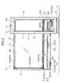


Classifications
-
- B—PERFORMING OPERATIONS; TRANSPORTING
- B61—RAILWAYS
- B61B—RAILWAY SYSTEMS; EQUIPMENT THEREFOR NOT OTHERWISE PROVIDED FOR
- B61B1/00—General arrangement of stations, platforms, or sidings; Railway networks; Rail vehicle marshalling systems
- B61B1/02—General arrangement of stations and platforms including protection devices for the passengers
-
- E—FIXED CONSTRUCTIONS
- E05—LOCKS; KEYS; WINDOW OR DOOR FITTINGS; SAFES
- E05D—HINGES OR SUSPENSION DEVICES FOR DOORS, WINDOWS OR WINGS
- E05D15/00—Suspension arrangements for wings
- E05D15/06—Suspension arrangements for wings for wings sliding horizontally more or less in their own plane
- E05D15/0617—Suspension arrangements for wings for wings sliding horizontally more or less in their own plane of cantilever type
-
- E—FIXED CONSTRUCTIONS
- E05—LOCKS; KEYS; WINDOW OR DOOR FITTINGS; SAFES
- E05F—DEVICES FOR MOVING WINGS INTO OPEN OR CLOSED POSITION; CHECKS FOR WINGS; WING FITTINGS NOT OTHERWISE PROVIDED FOR, CONCERNED WITH THE FUNCTIONING OF THE WING
- E05F15/00—Power-operated mechanisms for wings
- E05F15/60—Power-operated mechanisms for wings using electrical actuators
- E05F15/603—Power-operated mechanisms for wings using electrical actuators using rotary electromotors
- E05F15/632—Power-operated mechanisms for wings using electrical actuators using rotary electromotors for horizontally-sliding wings
-
- E—FIXED CONSTRUCTIONS
- E05—LOCKS; KEYS; WINDOW OR DOOR FITTINGS; SAFES
- E05F—DEVICES FOR MOVING WINGS INTO OPEN OR CLOSED POSITION; CHECKS FOR WINGS; WING FITTINGS NOT OTHERWISE PROVIDED FOR, CONCERNED WITH THE FUNCTIONING OF THE WING
- E05F15/00—Power-operated mechanisms for wings
- E05F15/60—Power-operated mechanisms for wings using electrical actuators
- E05F15/603—Power-operated mechanisms for wings using electrical actuators using rotary electromotors
- E05F15/632—Power-operated mechanisms for wings using electrical actuators using rotary electromotors for horizontally-sliding wings
- E05F15/643—Power-operated mechanisms for wings using electrical actuators using rotary electromotors for horizontally-sliding wings operated by flexible elongated pulling elements, e.g. belts, chains or cables
-
- E—FIXED CONSTRUCTIONS
- E05—LOCKS; KEYS; WINDOW OR DOOR FITTINGS; SAFES
- E05Y—INDEXING SCHEME ASSOCIATED WITH SUBCLASSES E05D AND E05F, RELATING TO CONSTRUCTION ELEMENTS, ELECTRIC CONTROL, POWER SUPPLY, POWER SIGNAL OR TRANSMISSION, USER INTERFACES, MOUNTING OR COUPLING, DETAILS, ACCESSORIES, AUXILIARY OPERATIONS NOT OTHERWISE PROVIDED FOR, APPLICATION THEREOF
- E05Y2201/00—Constructional elements; Accessories therefor
- E05Y2201/60—Suspension or transmission members; Accessories therefor
- E05Y2201/622—Suspension or transmission members elements
- E05Y2201/644—Flexible elongated pulling elements
- E05Y2201/652—Belts
-
- E—FIXED CONSTRUCTIONS
- E05—LOCKS; KEYS; WINDOW OR DOOR FITTINGS; SAFES
- E05Y—INDEXING SCHEME ASSOCIATED WITH SUBCLASSES E05D AND E05F, RELATING TO CONSTRUCTION ELEMENTS, ELECTRIC CONTROL, POWER SUPPLY, POWER SIGNAL OR TRANSMISSION, USER INTERFACES, MOUNTING OR COUPLING, DETAILS, ACCESSORIES, AUXILIARY OPERATIONS NOT OTHERWISE PROVIDED FOR, APPLICATION THEREOF
- E05Y2900/00—Application of doors, windows, wings or fittings thereof
- E05Y2900/40—Application of doors, windows, wings or fittings thereof for gates
- E05Y2900/402—Application of doors, windows, wings or fittings thereof for gates for cantilever gates
-
- E—FIXED CONSTRUCTIONS
- E05—LOCKS; KEYS; WINDOW OR DOOR FITTINGS; SAFES
- E05Y—INDEXING SCHEME ASSOCIATED WITH SUBCLASSES E05D AND E05F, RELATING TO CONSTRUCTION ELEMENTS, ELECTRIC CONTROL, POWER SUPPLY, POWER SIGNAL OR TRANSMISSION, USER INTERFACES, MOUNTING OR COUPLING, DETAILS, ACCESSORIES, AUXILIARY OPERATIONS NOT OTHERWISE PROVIDED FOR, APPLICATION THEREOF
- E05Y2900/00—Application of doors, windows, wings or fittings thereof
- E05Y2900/40—Application of doors, windows, wings or fittings thereof for gates
- E05Y2900/404—Application of doors, windows, wings or fittings thereof for gates for railway platform gates
-
- E—FIXED CONSTRUCTIONS
- E06—DOORS, WINDOWS, SHUTTERS, OR ROLLER BLINDS IN GENERAL; LADDERS
- E06B—FIXED OR MOVABLE CLOSURES FOR OPENINGS IN BUILDINGS, VEHICLES, FENCES OR LIKE ENCLOSURES IN GENERAL, e.g. DOORS, WINDOWS, BLINDS, GATES
- E06B11/00—Means for allowing passage through fences, barriers or the like, e.g. stiles
- E06B11/02—Gates; Doors
- E06B11/04—Gates; Doors characterised by the kind of suspension
- E06B11/045—Gates; Doors characterised by the kind of suspension exclusively for horizontally sliding gates
Definitions
- the present invention relates to a platform door device.
- a platform door device disclosed in the Patent Document 1 comprises a door, a guiding mechanism, and a driving mechanism.
- the door has a panel-shaped portion composed of a frame assembly and a glass plate set in the frame assembly.
- the door is adapted to be guided by the guiding mechanism in such a manner as to be movable forwardly and backwardly in a horizontal direction along an edge of a platform.
- the guiding mechanism includes a linear rail attached to the frame assembly of the door so as to extend in a direction of the movement of the door, and a slide block fixed to an inside of a guide box installed on the platform and slidably provided to the linear rail.
- the driving mechanism is provided inside the guide box and beneath the door.
- the driving mechanism includes a motor, a driving pulley, a pair of idler pulleys, and a toothed belt.
- the driving pulley has teeth, and is adapted to be rotated according to driving of the motor.
- the pair of idler pulleys are disposed to interpose the driving pulley therebetween.
- the toothed belt is wound over the pair of idler pulleys and meshed with the teeth of the driving pulley at a position between the idler pulleys.
- One end of the toothed belt is attached to a lower region of one end of the frame assembly in the movement direction of the door, through a bracket.
- the other end of the toothed belt is attached to a lower region of the other end of the frame assembly in the movement direction of the door, through a bracket.
- the toothed belt is held between the both ends of the frame assembly of the door, while being tightened with a given tension.
- the driving pulley is rotated according to driving of the motor, and thereby the toothed belt is moved.
- the toothed belt is moved.
- the door is pulled and thereby moved forwardly or backwardly.
- a gate on the platform is opened and closed.
- a platform door device comprises a door, and a driving mechanism for moving the door forwardly and backwardly to close and open a gate on a platform, wherein: the driving mechanism includes a motor, a rotation body adapted to be rotated by the motor, and a driven body adapted to be driven according to the rotation of the rotation body so as to move the door; and the door has a panel-shaped main body, and a base segment detachably joined to the main body and attached to the driven body.
- FIG. 1 is a front view of a platform door device 10 according to one embodiment of the present invention, when viewed in a direction from the side of a platform P to a rail track.
- the platform door device 10 comprises a pair of guide boxes 12, 12, and a pair of doors 14, 14.
- the pair of guide boxes 12, 12 are installed on the platform P along an edge of the platform P on the side of the track, while leaving a given distance therebetween.
- the guide box 12 is included in a concept of "guide body" in the present invention.
- a support box (illustration is omitted) and a fixed partition wall (illustration is omitted) may be installed adjacent to the guide box 12.
- Each of the doors 14 is a sliding type, and supported by a corresponding one of the guide boxes 12 in a movable manner.
- a space on the platform P will be divided into a track-side space, and a space inward of the track-side space (platform inner-side space).
- a gate 20 between the pair of guide boxes 12 is closed.
- the gate 20 is opened.
- Each of the guide boxes 12 is designed to be installable on the platform P, and adapted to allow the door 14 to penetrate therethrough in a direction along the track, i.e., a rightward-leftward direction in FIG. 1 .
- the platform door device 10 is formed as a so-called double sliding-type movable fence, it is not limited thereto.
- the platform door device may be formed as a single sliding-type movable fence which comprises a single guide box 12, and a single door 14 supported by the guide box 12.
- the guide box 12 and the door 14 on the left side in FIG. 1 are structurally symmetrical to the guide box 12 and the door 14 on the right side in FIG. 1 .
- the guide box 12 and the door 14 on the right side in FIG. 1 will be described here.
- the guide box 12 comprises a base 22 fixed to the platform P, and a casing 23 fixed to the base 22.
- the casing 23 has a bottom portion 25, a pair of end walls 27, 28, a pair of lateral walls 29, 30, a top portion 31, and a support pillar 32.
- the bottom portion 25 is fixed onto the base 22.
- the pair of end walls 27, 28 are disposed in spaced-apart relation to each other in a widthwise direction of the casing 23, i.e., in a door opening/closing direction.
- the pair of lateral walls 29, 30 are disposed in spaced-apart relation to each other in a thicknesswise direction of the casing 23, i.e., in a direction perpendicular to the door opening/closing direction.
- the top portion 31 connects between respective upper ends of the end walls 27, 28 and between respective upper ends of the lateral walls 29, 30.
- the guide box 12 is formed in a hollow structure having a rectangular cross-section in top plan view, as illustrated in FIGS. 4 and 5 .
- One of the pair of end walls located on the side of the gate 20 will hereinafter be referred to as "leading-side end wall 27", and the other end wall located on the opposite side will hereinafter be referred to as "trailing-side end wall 28".
- the lateral wall 30 located on the side of the track is provided with two auxiliary sensors 35 for detecting a passer passing through the gate 20, the auxiliary sensors 35 are arranged upper portion and lower portion of the lateral wall 30.
- the lateral wall 29 located on the platform inner side is formed with an opening 29a.
- This opening 29a is used during maintenance.
- a cover 29b to open and close the opening 29a is detachably attached to the lateral wall 29 (see FIG. 1 ).
- the leading-side end wall 27 is formed with an opening 27a
- the trailing-side end wall 28 is formed with an opening 28a.
- Each of the two openings 27a, 28a is designed to allow the door 14 to path therethrough.
- a trailing end of the door 14 is located adjacent to the trailing-side end wall 28, as illustrated in FIGS. 4 and 5 .
- a leading end of the door 14 is located adjacent to the leading-side end wall 27.
- the door 14 comprises a panel-shaped main body 40, and a base segment 42 detachably joined to the main body 40.
- the main body 40 includes a frame assembly 40a and a glass plate 40b.
- the frame assembly 40a is formed by assembling a plurality of hollow frame members together in a frame shape.
- the frame assembly 40a has an upper frame 40c, lower frame 40d, a leading frame 40e and a trailing frame 40f.
- the upper frame 40c forms an upper end of the frame assembly 40a
- the lower frame 40d forms a lower end of the frame assembly 40a.
- Each of the upper frame 40c and the lower frame 40d extends horizontally along the door opening/closing direction.
- the leading frame 40e forms a leading-side end of the frame assembly 40a
- the trailing frame 40f forms a trailing-side end of the frame assembly 40a.
- Each of the leading frame 40e and the trailing frame 40f extends in an upward-downward direction.
- the glass plate 40b serving as a panel member is fixedly attached to the frame assembly 40a so as to close a space formed by the frames 40c, 40d, 40e, 40f.
- a panel member to be fixedly attached to the frame assembly 40a is not limited to the glass plate 40b, but may be any other suitable type of panel member, such as a transparent plate made of resin or the like, or a metal panel.
- the base segment 42 has a width dimension equal to that of the frame assembly 40a, in the door opening/closing direction, i.e., in a widthwise direction of the door 14. Further, the base segment 42 has a leading-side end surface flush with a leading-side end surface of the frame assembly 40a, and a leading rubber 45 (see FIG. 2 ) is attached to cover across the two end surfaces.
- the base segment 42 is detachably joined to the lower frame 40d of the frame assembly 40a of the main body 40.
- An aftermentioned belt member 60 and an aftermentioned linear rail 64 are attached to the base segment 42.
- the base segment 42 has a joining portion 48, a mounting portion 49, and an extension portion 50.
- the joining portion 48, the mounting portion 49 and the extension portion 50 are integrally formed.
- the joining portion 48 is formed to have a given width in the upward-downward direction, and located on a lateral side of the lower frame 40d.
- the width of the joining portion 48 in the upward-downward direction is set to a value approximately equal to a width of the lower frame 40d in the upward-downward direction.
- a lateral surface of the joining portion 48 is joined to a lateral surface of the lower frame 40d.
- the base segment 42 is provided with a bridging portion 53.
- the bridging portion 53 is bridged between an upper end of the joining portion 48 and a track-side end of an aftermentioned upper section 49a of the mounting portion 49.
- the joining portion 48, the upper section 49a of the mounting portion 49, and the bridging portion 53 are joined to each other to form a closed loop cross-section.
- the joining portion 48 has a plurality of insertion holes formed in the door opening/closing direction at given intervals. Each of the insertion holes penetrates through the joining portion 48 in a horizontal direction.
- a nut plate 52 formed with a plurality of threaded holes is provided on a track-side of the joining portion 48 so as to extend along the joining portion 48. The nut plate 52 is non-rotatably held by the bridging portion 53.
- a portion of the lower frame 40d located on the side of the track is formed with insertion holes at positions corresponding to respective ones of the insertion holes of the joining portion 48.
- a bolt 51 inserted from the platform inner side into corresponding ones of the insertion holes of the lower frame 40d and the joining portion 48 is screwed in the nut plate 52, so that the joining portion 48 and the lower frame 40d are fixed together.
- the joining portion 48 is joined to the frame assembly 40a from a lateral direction.
- a platform inner-side portion of the lower frame 40d has a through-hole 40b1 formed to allow the bolt 51 to be inserted therethrough, and a cover 40b2 detachably attached thereto to close the through-hole 40b1.
- the frame assembly 40a can be separated from the base segment 42 by unfastening the bolts 51 from the nut plate 51.
- Each of the bolts 51 is laterally inserted into the corresponding insertion holes of the lower frame 40d and the joining portion 48 through the through-hole 40b1, so that fastening and unfastening operations for the bolts 52 and the nut plate 52 can be performed from the platform inner side.
- the mounting portion 49 is a region having rigidity capable of supporting the aftermentioned linear rail 64.
- the mounting portion 49 is formed in a hollow shape extending in a direction of the movement of the door 14.
- the mounting portion 49 is formed in a tubular shape having a generally rectangular cross-section.
- the mounting portion 49 has an upper section 49a, a lower section 49b, a first lateral section 49c, and a second lateral section 49d.
- the upper section 49a, the lower section 49b, the first lateral section 49c and the second lateral section 49d are integrally formed.
- the upper section 49a is a plate-shaped region which extends in a horizontal direction and has a given width in a thicknesswise direction of the door 14.
- the joining portion 48 is provided to extend upwardly from a widthwise intermediate region of the upper section 49a.
- the first lateral section 49c extends downwardly from one of widthwise opposite ends of the upper section 49a, and the second lateral section 49d extends downwardly from the other end of the upper section 49a.
- Each of the first lateral section 49c and the second lateral section 49d has a given height dimension.
- the first lateral section 49c makes up a platform inner-side lateral wall of the mounting portion 49, and the second lateral section 49d makes up a track-side lateral wall of the mounting portion 49.
- the lower section 49b connects a lower end of the first lateral section 49c and a lower end of the second lateral section 49d together, and extends between these lower ends in a horizontal direction.
- the extension portion 50 is provided to extend downwardly directly from the first lateral section 49c of the mounting portion 49.
- the extension portion 50 has a lower end 50a slightly bulging toward the track within a thickness range of the frame assembly 40a.
- a first belt joining portion 50b is provided on a trailing-side end of the lower end 50a, and a second belt joining portion 50c is provided on a leading-side end of the lower end 50a.
- the first belt joining portion 50b is a portion to be joined to one end of the aftermentioned belt member 60
- the second belt joining portion 50c is a portion to be joined to the other end of the aftermentioned belt member 60.
- the platform door device 10 comprises a driving mechanism 55 for moving the door 14 forwardly and backwardly to close and open the gate 20 on the platform P, and a guiding mechanism 56 for guiding the door 14 which is being moved forwardly or backwardly.
- the driving mechanism 55 and the guiding mechanism 56 are provided for each of the right and left doors 14.
- the driving mechanism 55 includes a motor 58, a driving pulley 59a, a pair of idler pulleys 59b, 59b, and a belt member 60.
- the driving pulley 59a is included in a concept of "rotation body” of the present invention
- the idler pulley 59b is included in a concept of "pulley” of the present invention.
- the belt member 60 is included in a concept of "driven body” of the present invention.
- the driving pulley 59a is disposed just below the frame assembly 40a, and formed to fall approximately within the thickness range of the frame assembly 40a.
- the motor 58 is fixed to the bottom portion 25 of the casing 23 through a motor bracket 61.
- the motor bracket 61 is fixed to the bottom portion 25 by a non-illustrated bolt.
- the motor bracket 61 has a size which falls within a width of the motor 58 in the thicknesswise direction of the guide box 12.
- the motor 58 is disposed below a lower end of the door 14. Further, a part of the motor 58 is located within the thickness range of the frame assembly 40a. More specifically, the motor 58 has a cylinder-shaped barrel portion 58a, and a part of the barrel portion 58a falls within the thickness range of the frame assembly 40a.
- the motor 58 has a gear portion 58b joined to the barrel portion 58a.
- the gear portion 58b has a width less than that of the barrel portion 58a, and an output shaft is provided in the gear portion 58b.
- the gear portion 58b is not located within the thickness range of the frame assembly 40a.
- the driving pulley 59 fixed to the output shaft provided to protrude from the gear portion 58b falls approximately within the thickness range of the frame assembly 40.
- the output shaft of the motor 58 is provided to protrude toward the platform inner side with respect to the motor 58, in a posture where it is rotatable about a horizontal axis. As above, a part of the motor 58 is disposed to fall within the thickness range of the frame assembly 40a, so that it becomes possible to reduce the thickness of the guide box 12 accordingly.
- the driving pulley 59a is fixed to the output shaft of the motor 58, and adapted to be rotated according to driving of the motor 58.
- the driving pulley 59a has teeth.
- the pair of idler pulleys 59b, 59b are arranged at positions above the driving pulley 59a, and separately on respective ones of opposite sides of a center position of the driving pulley 59a in the movement direction of the door 14.
- the idler pulleys 59b are disposed in spaced-apart relation to each other in the movement direction of the door 14.
- Each of the idler pulleys 59b is provided in a rotatable manner.
- a rotation axis of each of the idler pulleys 59b is arranged parallel to the output shaft of the motor 58.
- the belt member 60 is adapted to be driven according to rotation of the driving pulley 59a so as to move the door 14.
- the belt member 60 includes a toothed belt 60a, and a fastener 60b fixed to each of opposite ends of the toothed belt 60a.
- the toothed belt 60a is wound over the pair of idler pulleys 59b, 59b, and meshed with the teeth of the driving pulley 59a at a position between the idler pulleys 59b, 59b.
- the idler pulleys 59b press regions of the toothed belt 60a on both sides of a portion of the toothed belt 60a meshed with the driving pulley 59a. This makes it possible to ensure a length of a meshable region of the toothed belt 60a with the driving pulley 59a.
- the opposite ends of the belt member 60 are fixed to the base segment 42 of the door 14.
- the fastener 60b fixed to one (trailing-side) end of the toothed belt 60a is fastened to the first belt joining portion 50b provided on the trailing-side end of the lower end 50a of the extension portion 50 of the base segment 42.
- the fastener 60b fixed to the other (leading-side) end of the toothed belt 60a is fastened to the second belt joining portion 50c provided on the leading-side end of the lower end 50a of the extension portion 50 of the base segment 42 through an adjustment mechanism 62 capable of adjusting tension of the toothed belt 60a.
- the toothed belt 60a is tightened with a given tension, between the first belt joining portion 50b and the second belt joining portion 50c.
- the guiding mechanism 56 includes a linear rail 64 and a guide block 65.
- the linear rail 64 is attached to a widthwise intermediate region of the lower section 49b of the mounting portion 49 so as to extend in the movement direction of the door 14.
- the linear rail 64 has a length extending over approximately the entire width of the door 14 in the opening/closing direction of the door 14.
- the linear rail 64 is fixed to the mounting portion 49 while being oriented downwardly.
- the linear rail 64 extends outside the guide box 12, together with the door 14.
- the guide block 65 has a guide groove 65a formed in an upper surface thereof.
- the linear rail 64 is fitted in the guide groove 65a.
- the linear rail 64 is adapted to be slidingly moved with respect to the guide block 65.
- a structure in which the linear rail 64 and the guide block 65 are slidingly movable with respect to each other includes two structure: a first structure in which the linear rail 64 and the guide block 65 are slidingly movable with respect to each other while being in surface contact with each other; and a second structure in which the linear rail 64 and the guide block 65 are slidingly movable with respect to each other through a rolling element, such as a bearing ball.
- the two guide blocks 65 are provided within the guide box 12.
- the two guide blocks 65 are arranged while leaving a given distance therebetween in the door opening/closing direction.
- Each of the guide blocks 65 is supported by a support body 68 fixed to the inside of the guide box 12.
- the support body 68 has a pair of legs 68a, 68a fixed to the bottom portion 25 of the casing 23, a standing plate 68b disposed between the legs 68a, 68a, and a loading portion 68c fixed to respective upper ends of the legs 68a, 68a.
- the loading portion 68c is provided to extend over a range between the legs 68a, 68a and ranges located outside the legs 68a, 68a, in the door opening/closing direction.
- the two guide blocks 65 are fixed onto the loading portion 68c. In this state, the guide blocks 65 support the linear rail 64 from therebelow.
- the pair of legs 68a, 68a are disposed separately on both sides of the motor 58 in the door opening/closing direction (see FIG. 3 ).
- Each of the legs 68a, 68a has a lower end bent in a horizontal direction, and the lower end is fixed to the bottom portion 25 by a non-illustrated bolt.
- Each of the legs 68a has a reinforcement portion 68d at an intermediate height position thereof.
- the reinforcement portion 68d is provided at approximately the same height position as that of an upper end of the motor 58.
- a concave portion 68e is formed in a region of each of the legs 68a above the reinforcement portion 68d to avoid interference with the lower end 50a of the extension portion 50 and the belt member 60.
- the standing plate 68b is provided above the reinforcement portion 68d.
- the standing plate 68b is formed in a flat plate shape extending in a direction perpendicular to the output shaft of the motor 58.
- a pulley bracket 69 is fixed to the standing plate 68b, and the two idler pulleys 59b, 59b are rotatably attached to the pulley bracket 69 (see FIG. 3 ).
- the extension portion 50 of the base segment 42 is disposed on a side opposite to the track, i.e., on the platform inner side with respect to the linear rail 64 and the guide blocks 65.
- the extension portion 50 extends below the linear rail 64, the guide blocks 65 and the loading portion 68c.
- the extension portion 50 is formed with cutouts 50d.
- the two cutouts 50d are provided at respective positions between the first belt joining portion 50b and the second belt joining portion 50c to each of which a respective one of the opposite ends of the belt member 60 is fixed, in spaced-apart relation to each other in the door opening/closing direction.
- an oil hole 65b is provided in a region of the guide block 65 exposed through each of the cutouts 50d.
- the oil hole 65b is intended to feed lubrication oil to a sliding contact portion of each of the guide blocks 65 with respect to the linear rail 64.
- the oil hole 65b is used during maintenance. With the oil hole 65b being exposed through the each of the cutouts 50d, complexity in an operation of feeding oil to the oil hole 65b can be reduced.
- a cover panel 71 to cover the cutouts 50d is detachably attached to the base segment 42 of the door 42.
- the cover panel 71 is included in a concept of "cover” of the present invention. Based on covering the cutouts 50d by the cover panel 71, the guide blocks 65, the linear rail 64 and the belt member 60 located therebelow, exposed through the cutouts 50d, are hidden behind the cover panel 71 (see FIG. 7 ).
- the cover panel 71 is attached to each of a platform inner-side surface and a track-side surface of the base segment 42.
- a guide roller 72 is provided in an upper region of the inside of the guide box 12. An upper end of the door 14 is guided by the guide roller 72.
- the door 14 includes the base segment 42 which is detachably joined to the panel-shaped main body 40 and to which the belt member 60 of the driving mechanism 55 is attached.
- the main body 40 can be replaced by detaching the main body 40 from the base segment 42 while allowing the belt member 60 to be kept attached to the base segment 42, and attaching a new main body 40 to the base segment 42.
- This makes it possible to replace the main body 40 without exerting any influence on the driving mechanism 55, which eliminates a need for adjustment of the driving mechanism 55 during the replacement operation for the main body 40. Therefore, in the event of damage to the main body 40 of the door 14, a time required for the replacement operation can be reduced.
- the tension of the belt member 60 is loosened.
- the belt member 60 is attached to the base segment 42 of the door 14, and the main body 40 of the door 14 is detachably joined to the base segment 42, so that it becomes possible to allow the belt member 60 to be kept joined to the base segment 42 while being tightened with a given tension, during replacement of the main body 40.
- it is not necessary to perform adjustment of the tension of the belt member 60 i.e., a complicate operation in connection with the replacement of the main body 40.
- the base segment 42 of the door 14 is attached to the linear rail 64 of the guiding mechanism 56.
- the main body 40 can be replaced by detaching the main body 40 from the base segment 42 while allowing the linear rail 64 to be kept attached to the base segment 42, and attaching a new main body 40 to the base segment 42.
- the cutouts 50d to expose a part of the linear rail 64 and each of the guide blocks 65 are provided in the extension portion 50 of the base segment 42 located on the side opposite to the track with respect to the linear rail 64 and the guide blocks 65.
- the cover panel 71 to cover the cutouts 50d is detachably attached to the base segment 42.
- the cutouts 50d can be covered by the cover panel 71 so as to prevent foreign substances such as dust from entering through the cutouts 50d.
- the cover panel 71 can be detached so as to easily perform the maintenance of the linear rail 64 and the guide blocks 65 through the cutouts 50d.
- the present embodiment has been described based on a structure in which the door 14 penetrates through the guide box 12 as one example of a guide body, and the trailing end of the door 14 in the opened position protrudes from the guide box 12, the present invention is not limited to this structure.
- the door 14 may be housed in a door case body as another example of the guide body, when it is in the opened position.
- the present embodiment has been described based on a so-called belt drive system in which the driving mechanism 55 includes the driving pulley 59a and the belt member 60, and the door 14 is openably/closably driven by the belt member 60
- the driving mechanism may be a driving mechanism based on a rack-and-pinion drive system.
- a rack (illustration is omitted) may be fixed to a lower surface of the extension portion 50 located at the lower end of the door 14, and a pinion as a rotation body attached to the output shaft of the motor 58 may be meshed with the rack.
- the frame assembly 40a of the main body 40 is adapted to be detachable from the base segment 42, a burden of the replacement operation for the main body 40 can be reduced, and a time required for the replacement operation can be reduced.
- the linear rail 64 is attached to the mounting portion 49 of the base segment 42, and each of the guide blocks 65 is fixed to the support body 68 within the guide box 12.
- each of the guide blocks 65 may be attached to the mounting portion 49 of the base segment 42, and the linear rail 64 may be fixed to the support body 68 within the guide box 12.
- the guide body may be formed as a door case body adapted to house the door 14 in the opened position.
- the platform door device comprises a door, and a driving mechanism for moving the door forwardly and backwardly to close and open a gate on a platform, wherein: the driving mechanism includes a motor, a rotation body adapted to be rotated by the motor, and a driven body adapted to be driven according to the rotation of the rotation body so as to move the door; and the door includes a panel-shaped main body, and a base segment which is detachably joined to the main body and to which the driven body is attached.
- the door includes the base segment which is detachably joined to the panel-shaped main body and to which the driven body of the driving mechanism is attached.
- the main body can be replaced by detaching the main body from the base segment and attaching a new main body to the base segment while allowing the driven body to be kept attached to the base segment.
- This makes it possible to replace the panel-shaped main body of the door without exerting any influence on the driving mechanism, which eliminates a need for adjustment of the driving mechanism during the replacement operation for the main body. Therefore, in the platform door device, in the event of damage to the panel-shaped main body of the door, a time required for the replacement operation can be reduced.
- the driving mechanism may include a pair of pulleys separately arranged on respective ones of opposite sides of the rotation body, wherein the rotation body may have teeth;
- the driven body may consist of a belt member which is wound over the pair of pulleys and meshed with the teeth of the rotation body at a position between the pulleys;
- the base segment may be provided with a first belt joining portion joined to one end of the belt member, and a second belt joining portion joined to the other end of the belt member while allowing the belt member to be tightened with a given tension.
- the rotation body is rotated and the belt member is moved, according to driving of the motor, so that the door can be pulled by the belt member and thereby moved forwardly or backwardly.
- a structure where a belt member is used as the driven body to move the door if the belt member is directly joined to the main body of the door and tightened with a given tension, the tension of the belt member is loosened during replacement of the main body. Thus, it is necessary to re-adjust the tension of the belt member.
- the above platform door device comprises a guide body installed on the platform, and a guiding mechanism for guiding the door which is being moved forwardly or backwardly, wherein the guiding mechanism includes a linear rail extending in a direction of the movement of the door, and a guide block adapted to be slidingly moved with respect to the linear rail, and wherein one of the linear rail and the guide block is attached to the base segment, and a remaining one of the linear rail and the guide block is fixed to the guide body.
- the base segment of the door is attached to the linear rail or the guide block of the guiding mechanism.
- the main body can be replaced by detaching the main body from the base segment and attaching a new main body to the base segment while allowing the linear rail or the guide block to be kept attached to the base segment,.
- the base segment has a portion which is located on a side opposite to a track with respect to the linear rail and the guide block, and formed with a cutout for exposing at least a part of the linear rail and the guide block.
- the platform door device comprises a cover for covering the cutout, that is detachably attached to the base segment.
- the cutout can be covered by the cover so as to prevent foreign substances such as dust from entering through the cutout. Further, during maintenance, the cover can be detached so as to easily perform the maintenance of the linear rail and the guide block through the cutout.
- the platform door device makes it possible to reduce a time required for a replacement operation in the event of damage to the panel-shaped main body of the door.
Landscapes
- Engineering & Computer Science (AREA)
- Mechanical Engineering (AREA)
- Transportation (AREA)
- Platform Screen Doors And Railroad Systems (AREA)
- Power-Operated Mechanisms For Wings (AREA)
Abstract
Description
- The present invention relates to a platform door device.
- Heretofore, there has been known a platform door device installed along an edge of a platform on the side of a rail track in order to ensure safety of passengers. One example of such a platform door device is disclosed in the following Patent Document 1.
- A platform door device disclosed in the Patent Document 1 comprises a door, a guiding mechanism, and a driving mechanism.
- The door has a panel-shaped portion composed of a frame assembly and a glass plate set in the frame assembly. The door is adapted to be guided by the guiding mechanism in such a manner as to be movable forwardly and backwardly in a horizontal direction along an edge of a platform.
- The guiding mechanism includes a linear rail attached to the frame assembly of the door so as to extend in a direction of the movement of the door, and a slide block fixed to an inside of a guide box installed on the platform and slidably provided to the linear rail.
- The driving mechanism is provided inside the guide box and beneath the door. The driving mechanism includes a motor, a driving pulley, a pair of idler pulleys, and a toothed belt. The driving pulley has teeth, and is adapted to be rotated according to driving of the motor. The pair of idler pulleys are disposed to interpose the driving pulley therebetween. The toothed belt is wound over the pair of idler pulleys and meshed with the teeth of the driving pulley at a position between the idler pulleys. One end of the toothed belt is attached to a lower region of one end of the frame assembly in the movement direction of the door, through a bracket. The other end of the toothed belt is attached to a lower region of the other end of the frame assembly in the movement direction of the door, through a bracket. The toothed belt is held between the both ends of the frame assembly of the door, while being tightened with a given tension.
- In the driving mechanism, the driving pulley is rotated according to driving of the motor, and thereby the toothed belt is moved. According to the movement of the toothed belt, the door is pulled and thereby moved forwardly or backwardly. Then, according to the forward and backward movements of the door, a gate on the platform is opened and closed.
- In the above platform door device, in the event of damage to the panel-shaped portion of the door, the damaged door will be replaced with a new one. In this replacement operation, it is necessary to detach the toothed belt from the frame assembly. Then, after attaching a new door to the platform door device, and attaching the toothed belt between both ends of a lower portion of a frame assembly of the new door, it is necessary to perform adjustment of the driving mechanism, such as adjustment of belt tension. This causes a problem of an increase in time required for the replacement operation.
-
- Patent Document 1:
JP 2006-240529A - It is an object of the present invention to provide a platform door device capable of reducing a time required for a replacement operation in the event of damage to a panel-shaped portion of a door.
- A platform door device according to one aspect of the present invention comprises a door, and a driving mechanism for moving the door forwardly and backwardly to close and open a gate on a platform, wherein: the driving mechanism includes a motor, a rotation body adapted to be rotated by the motor, and a driven body adapted to be driven according to the rotation of the rotation body so as to move the door; and the door has a panel-shaped main body, and a base segment detachably joined to the main body and attached to the driven body.
-
-
FIG. 1 is a front view of a platform door device according to an embodiment of the present invention. -
FIG. 2 is a diagram illustrating a guide box, a door and a support box, on a right side inFIG. 1 . -
FIG. 3 is a fragmentary enlarged view of the structure inFIG. 2 , wherein a panel member located on an inner side of a platform is removed. -
FIG. 4 is a sectional view taken along the line IV-IV inFIG. 2 . -
FIG. 5 is a sectional view taken along the line V-V inFIG. 2 . -
FIG. 6 is a sectional view of the right guide box and door inFIG. 1 , when viewed from a trailing side of the door. -
FIG. 7 is a fragmentary enlarged view of the structure inFIG. 6 . - The embodiments of the present invention will be described below with reference to the drawings.
-
FIG. 1 is a front view of aplatform door device 10 according to one embodiment of the present invention, when viewed in a direction from the side of a platform P to a rail track. As illustrated inFIG. 1 , theplatform door device 10 comprises a pair ofguide boxes doors guide boxes guide box 12 is included in a concept of "guide body" in the present invention. A support box (illustration is omitted) and a fixed partition wall (illustration is omitted) may be installed adjacent to theguide box 12. Each of thedoors 14 is a sliding type, and supported by a corresponding one of theguide boxes 12 in a movable manner. - In cases where a large number of the
platform door devices 10 are arranged along the edge of the platform P while interposing the support box and the fixed partition wall therein, a space on the platform P will be divided into a track-side space, and a space inward of the track-side space (platform inner-side space). When the twodoors 14 are in their closed positions as illustrated inFIG. 1 , agate 20 between the pair ofguide boxes 12 is closed. On the other hand, when each of thedoors 14 is driven by anaftermentioned driving mechanism 55 and thereby moved backwardly to its opened position, thegate 20 is opened. - Each of the
guide boxes 12 is designed to be installable on the platform P, and adapted to allow thedoor 14 to penetrate therethrough in a direction along the track, i.e., a rightward-leftward direction inFIG. 1 . Although theplatform door device 10 is formed as a so-called double sliding-type movable fence, it is not limited thereto. For example, the platform door device may be formed as a single sliding-type movable fence which comprises asingle guide box 12, and asingle door 14 supported by theguide box 12. - With reference to
FIG. 2 to 7 , respective specific structures of theguide box 12 and thedoor 14 will be described below. Theguide box 12 and thedoor 14 on the left side inFIG. 1 are structurally symmetrical to theguide box 12 and thedoor 14 on the right side inFIG. 1 . Thus, only the structures of theguide box 12 and thedoor 14 on the right side inFIG. 1 will be described here. - As illustrated in
FIGS. 2 and3 , theguide box 12 comprises abase 22 fixed to the platform P, and acasing 23 fixed to thebase 22. Thecasing 23 has abottom portion 25, a pair ofend walls lateral walls top portion 31, and asupport pillar 32. Thebottom portion 25 is fixed onto thebase 22. The pair ofend walls casing 23, i.e., in a door opening/closing direction. The pair oflateral walls casing 23, i.e., in a direction perpendicular to the door opening/closing direction. Thetop portion 31 connects between respective upper ends of theend walls lateral walls guide box 12 is formed in a hollow structure having a rectangular cross-section in top plan view, as illustrated inFIGS. 4 and5 . One of the pair of end walls located on the side of thegate 20 will hereinafter be referred to as "leading-side end wall 27", and the other end wall located on the opposite side will hereinafter be referred to as "trailing-side end wall 28". In the pair oflateral walls lateral wall 30 located on the side of the track is provided with twoauxiliary sensors 35 for detecting a passer passing through thegate 20, theauxiliary sensors 35 are arranged upper portion and lower portion of thelateral wall 30. - As illustrated in
FIG. 2 , in the pair oflateral walls lateral wall 29 located on the platform inner side is formed with an opening 29a. This opening 29a is used during maintenance. Acover 29b to open and close theopening 29a is detachably attached to the lateral wall 29 (seeFIG. 1 ). - As illustrated in
FIGS. 4 and5 , the leading-side end wall 27 is formed with anopening 27a, and the trailing-side end wall 28 is formed with anopening 28a. Each of the twoopenings door 14 to path therethrough. When thedoor 14 is in the closed position, a trailing end of thedoor 14 is located adjacent to the trailing-side end wall 28, as illustrated inFIGS. 4 and5 . On the other hand, when thedoor 14 is in the opened position, a leading end of thedoor 14 is located adjacent to the leading-side end wall 27. - As illustrated, for example, in
FIG. 2 , thedoor 14 comprises a panel-shapedmain body 40, and abase segment 42 detachably joined to themain body 40. - The
main body 40 includes aframe assembly 40a and aglass plate 40b. Theframe assembly 40a is formed by assembling a plurality of hollow frame members together in a frame shape. Theframe assembly 40a has anupper frame 40c,lower frame 40d, a leadingframe 40e and a trailingframe 40f. Theupper frame 40c forms an upper end of theframe assembly 40a, and thelower frame 40d forms a lower end of theframe assembly 40a. Each of theupper frame 40c and thelower frame 40d extends horizontally along the door opening/closing direction. The leadingframe 40e forms a leading-side end of theframe assembly 40a, and the trailingframe 40f forms a trailing-side end of theframe assembly 40a. Each of the leadingframe 40e and the trailingframe 40f extends in an upward-downward direction. Theglass plate 40b serving as a panel member is fixedly attached to theframe assembly 40a so as to close a space formed by theframes frame assembly 40a is not limited to theglass plate 40b, but may be any other suitable type of panel member, such as a transparent plate made of resin or the like, or a metal panel. - The
base segment 42 has a width dimension equal to that of theframe assembly 40a, in the door opening/closing direction, i.e., in a widthwise direction of thedoor 14. Further, thebase segment 42 has a leading-side end surface flush with a leading-side end surface of theframe assembly 40a, and a leading rubber 45 (seeFIG. 2 ) is attached to cover across the two end surfaces. - The
base segment 42 is detachably joined to thelower frame 40d of theframe assembly 40a of themain body 40. Anaftermentioned belt member 60 and an aftermentionedlinear rail 64 are attached to thebase segment 42. As illustrated inFIG. 7 , thebase segment 42 has a joiningportion 48, a mountingportion 49, and anextension portion 50. The joiningportion 48, the mountingportion 49 and theextension portion 50 are integrally formed. The joiningportion 48 is formed to have a given width in the upward-downward direction, and located on a lateral side of thelower frame 40d. The width of the joiningportion 48 in the upward-downward direction is set to a value approximately equal to a width of thelower frame 40d in the upward-downward direction. A lateral surface of the joiningportion 48 is joined to a lateral surface of thelower frame 40d. Thebase segment 42 is provided with a bridgingportion 53. The bridgingportion 53 is bridged between an upper end of the joiningportion 48 and a track-side end of an aftermentionedupper section 49a of the mountingportion 49. The joiningportion 48, theupper section 49a of the mountingportion 49, and the bridgingportion 53 are joined to each other to form a closed loop cross-section. - The joining
portion 48 has a plurality of insertion holes formed in the door opening/closing direction at given intervals. Each of the insertion holes penetrates through the joiningportion 48 in a horizontal direction. Anut plate 52 formed with a plurality of threaded holes is provided on a track-side of the joiningportion 48 so as to extend along the joiningportion 48. Thenut plate 52 is non-rotatably held by the bridgingportion 53. On the other hand, a portion of thelower frame 40d located on the side of the track is formed with insertion holes at positions corresponding to respective ones of the insertion holes of the joiningportion 48. Abolt 51 inserted from the platform inner side into corresponding ones of the insertion holes of thelower frame 40d and the joiningportion 48 is screwed in thenut plate 52, so that the joiningportion 48 and thelower frame 40d are fixed together. In other words, the joiningportion 48 is joined to theframe assembly 40a from a lateral direction. A platform inner-side portion of thelower frame 40d has a through-hole 40b1 formed to allow thebolt 51 to be inserted therethrough, and a cover 40b2 detachably attached thereto to close the through-hole 40b1. - The
frame assembly 40a can be separated from thebase segment 42 by unfastening thebolts 51 from thenut plate 51. Each of thebolts 51 is laterally inserted into the corresponding insertion holes of thelower frame 40d and the joiningportion 48 through the through-hole 40b1, so that fastening and unfastening operations for thebolts 52 and thenut plate 52 can be performed from the platform inner side. - The mounting
portion 49 is a region having rigidity capable of supporting the aftermentionedlinear rail 64. The mountingportion 49 is formed in a hollow shape extending in a direction of the movement of thedoor 14. The mountingportion 49 is formed in a tubular shape having a generally rectangular cross-section. The mountingportion 49 has anupper section 49a, alower section 49b, a firstlateral section 49c, and a secondlateral section 49d. Theupper section 49a, thelower section 49b, the firstlateral section 49c and the secondlateral section 49d are integrally formed. Theupper section 49a is a plate-shaped region which extends in a horizontal direction and has a given width in a thicknesswise direction of thedoor 14. The joiningportion 48 is provided to extend upwardly from a widthwise intermediate region of theupper section 49a. - The first
lateral section 49c extends downwardly from one of widthwise opposite ends of theupper section 49a, and the secondlateral section 49d extends downwardly from the other end of theupper section 49a. Each of the firstlateral section 49c and the secondlateral section 49d has a given height dimension. The firstlateral section 49c makes up a platform inner-side lateral wall of the mountingportion 49, and the secondlateral section 49d makes up a track-side lateral wall of the mountingportion 49. Thelower section 49b connects a lower end of the firstlateral section 49c and a lower end of the secondlateral section 49d together, and extends between these lower ends in a horizontal direction. - The
extension portion 50 is provided to extend downwardly directly from the firstlateral section 49c of the mountingportion 49. Theextension portion 50 has alower end 50a slightly bulging toward the track within a thickness range of theframe assembly 40a. A firstbelt joining portion 50b is provided on a trailing-side end of thelower end 50a, and a secondbelt joining portion 50c is provided on a leading-side end of thelower end 50a. The firstbelt joining portion 50b is a portion to be joined to one end of theaftermentioned belt member 60, and the secondbelt joining portion 50c is a portion to be joined to the other end of theaftermentioned belt member 60. - The
platform door device 10 comprises adriving mechanism 55 for moving thedoor 14 forwardly and backwardly to close and open thegate 20 on the platform P, and aguiding mechanism 56 for guiding thedoor 14 which is being moved forwardly or backwardly. Thedriving mechanism 55 and theguiding mechanism 56 are provided for each of the right and leftdoors 14. - As illustrated in
FIGS. 2 and3 , thedriving mechanism 55 includes amotor 58, a drivingpulley 59a, a pair ofidler pulleys belt member 60. The drivingpulley 59a is included in a concept of "rotation body" of the present invention, and theidler pulley 59b is included in a concept of "pulley" of the present invention. Further, thebelt member 60 is included in a concept of "driven body" of the present invention. The drivingpulley 59a is disposed just below theframe assembly 40a, and formed to fall approximately within the thickness range of theframe assembly 40a. - The
motor 58 is fixed to thebottom portion 25 of thecasing 23 through amotor bracket 61. Themotor bracket 61 is fixed to thebottom portion 25 by a non-illustrated bolt. Themotor bracket 61 has a size which falls within a width of themotor 58 in the thicknesswise direction of theguide box 12. - The
motor 58 is disposed below a lower end of thedoor 14. Further, a part of themotor 58 is located within the thickness range of theframe assembly 40a. More specifically, themotor 58 has a cylinder-shapedbarrel portion 58a, and a part of thebarrel portion 58a falls within the thickness range of theframe assembly 40a. Themotor 58 has agear portion 58b joined to thebarrel portion 58a. Thegear portion 58b has a width less than that of thebarrel portion 58a, and an output shaft is provided in thegear portion 58b. Thegear portion 58b is not located within the thickness range of theframe assembly 40a. Thus, the driving pulley 59 fixed to the output shaft provided to protrude from thegear portion 58b falls approximately within the thickness range of theframe assembly 40. The output shaft of themotor 58 is provided to protrude toward the platform inner side with respect to themotor 58, in a posture where it is rotatable about a horizontal axis. As above, a part of themotor 58 is disposed to fall within the thickness range of theframe assembly 40a, so that it becomes possible to reduce the thickness of theguide box 12 accordingly. - The driving
pulley 59a is fixed to the output shaft of themotor 58, and adapted to be rotated according to driving of themotor 58. The drivingpulley 59a has teeth. - The pair of
idler pulleys pulley 59a, and separately on respective ones of opposite sides of a center position of the drivingpulley 59a in the movement direction of thedoor 14. The idler pulleys 59b are disposed in spaced-apart relation to each other in the movement direction of thedoor 14. Each of theidler pulleys 59b is provided in a rotatable manner. A rotation axis of each of theidler pulleys 59b is arranged parallel to the output shaft of themotor 58. - The
belt member 60 is adapted to be driven according to rotation of the drivingpulley 59a so as to move thedoor 14. Thebelt member 60 includes atoothed belt 60a, and afastener 60b fixed to each of opposite ends of thetoothed belt 60a. - The
toothed belt 60a is wound over the pair ofidler pulleys pulley 59a at a position between theidler pulleys toothed belt 60a on both sides of a portion of thetoothed belt 60a meshed with the drivingpulley 59a. This makes it possible to ensure a length of a meshable region of thetoothed belt 60a with the drivingpulley 59a. Under a condition that teeth of thetoothed belt 60a are meshed with the teeth of the drivingpulley 59a, the opposite ends of thebelt member 60 are fixed to thebase segment 42 of thedoor 14. - The
fastener 60b fixed to one (trailing-side) end of thetoothed belt 60a is fastened to the firstbelt joining portion 50b provided on the trailing-side end of thelower end 50a of theextension portion 50 of thebase segment 42. Thefastener 60b fixed to the other (leading-side) end of thetoothed belt 60a is fastened to the secondbelt joining portion 50c provided on the leading-side end of thelower end 50a of theextension portion 50 of thebase segment 42 through anadjustment mechanism 62 capable of adjusting tension of thetoothed belt 60a. Based on this structure, thetoothed belt 60a is tightened with a given tension, between the firstbelt joining portion 50b and the secondbelt joining portion 50c. Thus, when the drivingpulley 59a is rotated according to driving of themotor 58, thebelt member 60 is moved according to the rotation of the drivingpulley 59a, so that thedoor 14 is pulled by the belt member 60and thereby moved forwardly or backwardly. - The guiding
mechanism 56 includes alinear rail 64 and aguide block 65. Thelinear rail 64 is attached to a widthwise intermediate region of thelower section 49b of the mountingportion 49 so as to extend in the movement direction of thedoor 14. Thelinear rail 64 has a length extending over approximately the entire width of thedoor 14 in the opening/closing direction of thedoor 14. Thelinear rail 64 is fixed to the mountingportion 49 while being oriented downwardly. Thelinear rail 64 extends outside theguide box 12, together with thedoor 14. - The
guide block 65 has aguide groove 65a formed in an upper surface thereof. Thelinear rail 64 is fitted in theguide groove 65a. Thus, thelinear rail 64 is adapted to be slidingly moved with respect to theguide block 65. A structure in which thelinear rail 64 and theguide block 65 are slidingly movable with respect to each other includes two structure: a first structure in which thelinear rail 64 and theguide block 65 are slidingly movable with respect to each other while being in surface contact with each other; and a second structure in which thelinear rail 64 and theguide block 65 are slidingly movable with respect to each other through a rolling element, such as a bearing ball. - The two guide blocks 65 are provided within the
guide box 12. The two guide blocks 65 are arranged while leaving a given distance therebetween in the door opening/closing direction. Each of the guide blocks 65 is supported by asupport body 68 fixed to the inside of theguide box 12. Thesupport body 68 has a pair oflegs bottom portion 25 of thecasing 23, a standingplate 68b disposed between thelegs loading portion 68c fixed to respective upper ends of thelegs loading portion 68c is provided to extend over a range between thelegs legs loading portion 68c. In this state, the guide blocks 65 support thelinear rail 64 from therebelow. - The pair of
legs motor 58 in the door opening/closing direction (seeFIG. 3 ). Each of thelegs bottom portion 25 by a non-illustrated bolt. - Each of the
legs 68a has areinforcement portion 68d at an intermediate height position thereof. Thereinforcement portion 68d is provided at approximately the same height position as that of an upper end of themotor 58. As illustrated inFIG. 7 , aconcave portion 68e is formed in a region of each of thelegs 68a above thereinforcement portion 68d to avoid interference with thelower end 50a of theextension portion 50 and thebelt member 60. - The standing
plate 68b is provided above thereinforcement portion 68d. The standingplate 68b is formed in a flat plate shape extending in a direction perpendicular to the output shaft of themotor 58. Apulley bracket 69 is fixed to the standingplate 68b, and the twoidler pulleys FIG. 3 ). - The
extension portion 50 of thebase segment 42 is disposed on a side opposite to the track, i.e., on the platform inner side with respect to thelinear rail 64 and the guide blocks 65. Theextension portion 50 extends below thelinear rail 64, the guide blocks 65 and theloading portion 68c. As illustrated inFIGS. 2 and3 , theextension portion 50 is formed withcutouts 50d. The twocutouts 50d are provided at respective positions between the firstbelt joining portion 50b and the secondbelt joining portion 50c to each of which a respective one of the opposite ends of thebelt member 60 is fixed, in spaced-apart relation to each other in the door opening/closing direction. Based on forming thecutouts 50d in theextension portion 50, a part of each of the guide blocks 65 and a part of thelinear rail 64 are exposed through thecutouts 50d, when viewed from the platform inner side. Thus, through thecutouts 50d, inspection of thelinear rail 64, for example, an inspection as to whether thelinear rail 64 is damaged, can be easily performed. Further, anoil hole 65b is provided in a region of theguide block 65 exposed through each of thecutouts 50d. Theoil hole 65b is intended to feed lubrication oil to a sliding contact portion of each of the guide blocks 65 with respect to thelinear rail 64. Theoil hole 65b is used during maintenance. With theoil hole 65b being exposed through the each of thecutouts 50d, complexity in an operation of feeding oil to theoil hole 65b can be reduced. - A
cover panel 71 to cover thecutouts 50d is detachably attached to thebase segment 42 of thedoor 42. Thecover panel 71 is included in a concept of "cover" of the present invention. Based on covering thecutouts 50d by thecover panel 71, the guide blocks 65, thelinear rail 64 and thebelt member 60 located therebelow, exposed through thecutouts 50d, are hidden behind the cover panel 71 (seeFIG. 7 ). Thecover panel 71 is attached to each of a platform inner-side surface and a track-side surface of thebase segment 42. - As illustrated in
FIG. 6 , aguide roller 72 is provided in an upper region of the inside of theguide box 12. An upper end of thedoor 14 is guided by theguide roller 72. - As described above, in the
platform door device 10 according to the present embodiment, thedoor 14 includes thebase segment 42 which is detachably joined to the panel-shapedmain body 40 and to which thebelt member 60 of thedriving mechanism 55 is attached. Thus, in the event of damage to the panel-shapedmain body 40, for example, in the event that theglass plate 40b of themain body 40 is broken, themain body 40 can be replaced by detaching themain body 40 from thebase segment 42 while allowing thebelt member 60 to be kept attached to thebase segment 42, and attaching a newmain body 40 to thebase segment 42. This makes it possible to replace themain body 40 without exerting any influence on thedriving mechanism 55, which eliminates a need for adjustment of thedriving mechanism 55 during the replacement operation for themain body 40. Therefore, in the event of damage to themain body 40 of thedoor 14, a time required for the replacement operation can be reduced. - Meanwhile, in a structure where the
belt member 60 is directly joined to the main body of thedoor 14 and tightened with a given tension, when the main body is detached from thebelt member 60 during replacement of the main body, the tension of thebelt member 60 is loosened. Thus, it is necessary to re-adjust the tension of thebelt member 60. However, in the structure according to the present embodiment, thebelt member 60 is attached to thebase segment 42 of thedoor 14, and themain body 40 of thedoor 14 is detachably joined to thebase segment 42, so that it becomes possible to allow thebelt member 60 to be kept joined to thebase segment 42 while being tightened with a given tension, during replacement of themain body 40. Thus, it is not necessary to perform adjustment of the tension of thebelt member 60, i.e., a complicate operation in connection with the replacement of themain body 40. - In the present embodiment, the
base segment 42 of thedoor 14 is attached to thelinear rail 64 of theguiding mechanism 56. Thus, in the event of damage to themain body 40 of thedoor 14, themain body 40 can be replaced by detaching themain body 40 from thebase segment 42 while allowing thelinear rail 64 to be kept attached to thebase segment 42, and attaching a newmain body 40 to thebase segment 42. In other words, during replacement of themain body 40, it is only necessary to detach themain body 40 from thebase segment 42 and attach a newmain body 40 to thebase segment 42, so that it becomes possible to omit an operation of attaching and detaching thedoor 14 with respect to each of thebelt member 60 of thedriving mechanism 55 and thelinear rail 64 of theguiding mechanism 56. This makes it possible to simplify the replacement operation for themain body 40 of thedoor 14. - In the present embodiment, the
cutouts 50d to expose a part of thelinear rail 64 and each of the guide blocks 65 are provided in theextension portion 50 of thebase segment 42 located on the side opposite to the track with respect to thelinear rail 64 and the guide blocks 65. Thus, even if theextension portion 50 covers thelinear rail 64 and the guide blocks 65, at a position opposite to the track with respect to thelinear rail 64 and the guide blocks 65, maintenance of thelinear rail 64 and the guide blocks 65 can be performed on the platform P through thecutouts 50d. This makes it possible to easily perform the maintenance of theguiding mechanism 56. - In the present embodiment, the
cover panel 71 to cover thecutouts 50d is detachably attached to thebase segment 42. Thus, during a normal actuation of theplatform door device 10, thecutouts 50d can be covered by thecover panel 71 so as to prevent foreign substances such as dust from entering through thecutouts 50d. Further, during maintenance, thecover panel 71 can be detached so as to easily perform the maintenance of thelinear rail 64 and the guide blocks 65 through thecutouts 50d. - It is understood that the present invention is not limited to the present embodiment, but various changes and modifications may be made therein without departing from the spirits and scope of the present invention.
- For example, although the present embodiment has been described based on a structure in which the
door 14 penetrates through theguide box 12 as one example of a guide body, and the trailing end of thedoor 14 in the opened position protrudes from theguide box 12, the present invention is not limited to this structure. For example, thedoor 14 may be housed in a door case body as another example of the guide body, when it is in the opened position. - Although the present embodiment has been described based on a so-called belt drive system in which the
driving mechanism 55 includes the drivingpulley 59a and thebelt member 60, and thedoor 14 is openably/closably driven by thebelt member 60, the present invention is not limited thereto. For example, the driving mechanism may be a driving mechanism based on a rack-and-pinion drive system. In this case, a rack (illustration is omitted) may be fixed to a lower surface of theextension portion 50 located at the lower end of thedoor 14, and a pinion as a rotation body attached to the output shaft of themotor 58 may be meshed with the rack. In the driving mechanism based on the rack-and-pinion drive system, as long as theframe assembly 40a of themain body 40 is adapted to be detachable from thebase segment 42, a burden of the replacement operation for themain body 40 can be reduced, and a time required for the replacement operation can be reduced. - In the present embodiment, the
linear rail 64 is attached to the mountingportion 49 of thebase segment 42, and each of the guide blocks 65 is fixed to thesupport body 68 within theguide box 12. Alternatively, each of the guide blocks 65 may be attached to the mountingportion 49 of thebase segment 42, and thelinear rail 64 may be fixed to thesupport body 68 within theguide box 12. In this case, the guide body may be formed as a door case body adapted to house thedoor 14 in the opened position. - The above embodiment can be summarized as follows.
- The platform door device according to the above embodiment comprises a door, and a driving mechanism for moving the door forwardly and backwardly to close and open a gate on a platform, wherein: the driving mechanism includes a motor, a rotation body adapted to be rotated by the motor, and a driven body adapted to be driven according to the rotation of the rotation body so as to move the door; and the door includes a panel-shaped main body, and a base segment which is detachably joined to the main body and to which the driven body is attached.
- In this platform door device, the door includes the base segment which is detachably joined to the panel-shaped main body and to which the driven body of the driving mechanism is attached. Thus, in the event of damage to the panel-shaped main body, the main body can be replaced by detaching the main body from the base segment and attaching a new main body to the base segment while allowing the driven body to be kept attached to the base segment. This makes it possible to replace the panel-shaped main body of the door without exerting any influence on the driving mechanism, which eliminates a need for adjustment of the driving mechanism during the replacement operation for the main body. Therefore, in the platform door device, in the event of damage to the panel-shaped main body of the door, a time required for the replacement operation can be reduced.
- In the above platform door device, the driving mechanism may include a pair of pulleys separately arranged on respective ones of opposite sides of the rotation body, wherein the rotation body may have teeth; the driven body may consist of a belt member which is wound over the pair of pulleys and meshed with the teeth of the rotation body at a position between the pulleys; and the base segment may be provided with a first belt joining portion joined to one end of the belt member, and a second belt joining portion joined to the other end of the belt member while allowing the belt member to be tightened with a given tension.
- In this structure, the rotation body is rotated and the belt member is moved, according to driving of the motor, so that the door can be pulled by the belt member and thereby moved forwardly or backwardly. This makes it possible to form a specific structure of the driving mechanism for moving the door forwardly and backwardly. In a structure where a belt member is used as the driven body to move the door, if the belt member is directly joined to the main body of the door and tightened with a given tension, the tension of the belt member is loosened during replacement of the main body. Thus, it is necessary to re-adjust the tension of the belt member. However, in the structure according to the above embodiment, it becomes possible to allow the belt member to be kept joined to the base segment while being tightened with a given tension, during replacement of the main body of the door. Thus, it is not necessary to perform the complicate adjustment.
- Preferably, the above platform door device comprises a guide body installed on the platform, and a guiding mechanism for guiding the door which is being moved forwardly or backwardly, wherein the guiding mechanism includes a linear rail extending in a direction of the movement of the door, and a guide block adapted to be slidingly moved with respect to the linear rail, and wherein one of the linear rail and the guide block is attached to the base segment, and a remaining one of the linear rail and the guide block is fixed to the guide body.
- In this structure, the base segment of the door is attached to the linear rail or the guide block of the guiding mechanism. Thus, in the event of damage to the panel-shaped main body of the door, the main body can be replaced by detaching the main body from the base segment and attaching a new main body to the base segment while allowing the linear rail or the guide block to be kept attached to the base segment,. In other words, in this structure, during replacement of the main body of the door, it is only necessary to detach the main body from the base segment and attach a new main body to the base segment, so that it becomes possible to omit an operation of attaching and detaching the door with respect to each of the driven member of the driving mechanism and the linear rail or the guide block of the guiding mechanism. This makes it possible to simplify the replacement operation for the main body of the door.
- In this case, it is preferable that the base segment has a portion which is located on a side opposite to a track with respect to the linear rail and the guide block, and formed with a cutout for exposing at least a part of the linear rail and the guide block.
- In this structure, even if a portion of the base segment covers the linear rail and the guide block, at a position opposite to the track with respect to the linear rail and the guide block, maintenance of the linear rail and the guide block can be performed on the platform through the cutout. This makes it possible to easily perform the maintenance of the guiding mechanism.
- Further, in this case, it is preferable that the platform door device comprises a cover for covering the cutout, that is detachably attached to the base segment.
- In this structure, during a normal actuation of the platform door device, the cutout can be covered by the cover so as to prevent foreign substances such as dust from entering through the cutout. Further, during maintenance, the cover can be detached so as to easily perform the maintenance of the linear rail and the guide block through the cutout.
- As mentioned above, the platform door device according to the above embodiment makes it possible to reduce a time required for a replacement operation in the event of damage to the panel-shaped main body of the door.
Claims (5)
- A platform door device comprising a door, and a driving mechanism for moving the door forwardly and backwardly to close and open a gate on a platform, wherein:the driving mechanism includes a motor, a rotation body adapted to be rotated by the motor, and a driven body adapted to be driven according to the rotation of the rotation body so as to move the door; andthe door includes a panel-shaped main body, and a base segment which is detachably joined to the main body and to which the driven body is attached.
- The platform door device according to claim 1, wherein the driving mechanism includes a pair of pulleys separately arranged on respective ones of opposite sides of the rotation body, and wherein:the rotation body has teeth;the driven body consists of a belt member which is wound over the pair of pulleys and meshed with the teeth of the rotation body at a position between the pulleys; andthe base segment is provided with a first belt joining portion joined to one end of the belt member, and a second belt joining portion joined to the other end of the belt member while allowing the belt member to be tightened with a given tension.
- The platform door device according to claim 1 or 2, which comprises a guide body installed on the platform, and a guiding mechanism for guiding the door which is being moved forwardly or backwardly, wherein the guiding mechanism includes a linear rail extending in a direction of the movement of the door, and a guide block adapted to be slidingly moved with respect to the linear rail, and wherein one of the linear rail and the guide block is attached to the base segment, and a remaining one of the linear rail and the guide block is fixed to the guide body.
- The platform door device according to claim 3, wherein the base segment has a portion which is located on a side opposite to a track with respect to the linear rail and the guide block, and formed with a cutout for exposing at least a part of the linear rail and the guide block.
- The platform door device according to claim 4, which comprises a cover, for covering the cutout, that is detachably attached to the base segment.
Applications Claiming Priority (2)
| Application Number | Priority Date | Filing Date | Title |
|---|---|---|---|
| JP2009036156A JP2010188896A (en) | 2009-02-19 | 2009-02-19 | Platform door device |
| PCT/JP2010/001092 WO2010095454A1 (en) | 2009-02-19 | 2010-02-19 | Railway platform door device |
Publications (3)
| Publication Number | Publication Date |
|---|---|
| EP2399796A1 true EP2399796A1 (en) | 2011-12-28 |
| EP2399796A4 EP2399796A4 (en) | 2013-11-27 |
| EP2399796B1 EP2399796B1 (en) | 2020-05-20 |
Family
ID=42633741
Family Applications (1)
| Application Number | Title | Priority Date | Filing Date |
|---|---|---|---|
| EP10743583.6A Active EP2399796B1 (en) | 2009-02-19 | 2010-02-19 | Railway platform door device |
Country Status (7)
| Country | Link |
|---|---|
| US (1) | US8464470B2 (en) |
| EP (1) | EP2399796B1 (en) |
| JP (1) | JP2010188896A (en) |
| KR (1) | KR101333615B1 (en) |
| CN (1) | CN102481939B (en) |
| TW (1) | TWI541153B (en) |
| WO (1) | WO2010095454A1 (en) |
Cited By (1)
| Publication number | Priority date | Publication date | Assignee | Title |
|---|---|---|---|---|
| EP2996920A4 (en) * | 2013-05-13 | 2016-12-28 | Overhead Door Corp | SCREEN DOOR SYSTEM FOR PLATFORM |
Families Citing this family (28)
| Publication number | Priority date | Publication date | Assignee | Title |
|---|---|---|---|---|
| JP2012056494A (en) * | 2010-09-10 | 2012-03-22 | Nabtesco Corp | Platform door device |
| CN102561877A (en) * | 2011-12-29 | 2012-07-11 | 深圳市方大自动化系统有限公司 | Half-high safety door transmission system |
| US20140259930A1 (en) * | 2013-03-13 | 2014-09-18 | Chester A. Gilliam | Portable gate |
| JP6184264B2 (en) * | 2013-09-11 | 2017-08-23 | 日本車輌製造株式会社 | Movable home fence |
| USD782700S1 (en) * | 2013-09-30 | 2017-03-28 | Kone Corporation | Access gate set |
| USD787706S1 (en) * | 2014-05-05 | 2017-05-23 | Nazbin Goddard | Storage enclosure |
| JP5955932B2 (en) * | 2014-12-02 | 2016-07-20 | ナブテスコ株式会社 | Platform door equipment |
| JP6660087B2 (en) * | 2015-03-06 | 2020-03-04 | ナブテスコ株式会社 | Platform door |
| FR3039581B1 (en) * | 2015-07-31 | 2017-07-28 | Faiveley Transp Tours | SYSTEM FOR GUIDING AND SUPPORTING A DOOR BEARING DOOR VANTAIL |
| JP6628551B2 (en) * | 2015-10-27 | 2020-01-08 | 三菱電機株式会社 | Movable platform fence and transparent member replacement method for movable platform fence |
| JP6899463B2 (en) * | 2015-12-17 | 2021-07-07 | ナブテスコ株式会社 | Multiple doors and multiple door switchgear |
| JP6677501B2 (en) * | 2015-12-17 | 2020-04-08 | ナブテスコ株式会社 | Multiple doors and multiple door openers |
| CN107642301A (en) * | 2016-07-20 | 2018-01-30 | 刘春梅 | A kind of half wealthy family with roller rail construction |
| CN109209162B (en) * | 2017-06-30 | 2021-07-09 | 比亚迪股份有限公司 | Sliding doors for platform doors and platform doors having the same |
| US10995538B2 (en) * | 2017-07-03 | 2021-05-04 | Hall Labs Llc | Retrofittable motorized pulley sliding window or door system |
| US10808446B2 (en) * | 2017-11-24 | 2020-10-20 | Hall Labs Llc | Pulley-driven automated window or door system |
| US20190309562A1 (en) * | 2018-04-05 | 2019-10-10 | David R. Hall | Automated Window System with Wireless Control |
| US10697225B2 (en) * | 2018-05-03 | 2020-06-30 | Qianliang QIU | Gate opening apparatus |
| CN108915512A (en) * | 2018-08-07 | 2018-11-30 | 南京尚泰科技有限公司 | A kind of the carrying driving device and composite door of sliding rotary composite door |
| US12577832B2 (en) * | 2020-03-12 | 2026-03-17 | Assa Abloy Entrance Systems Ab | Door operation system |
| WO2022071096A1 (en) * | 2020-10-02 | 2022-04-07 | パナソニックIpマネジメント株式会社 | Door opening/closing device |
| CN112761093B (en) * | 2020-12-23 | 2022-05-17 | 深圳市安之眼科技有限公司 | Gate frame applied to automatic identification gate and machining die thereof |
| USD1092785S1 (en) * | 2023-06-19 | 2025-09-09 | Assa Abloy Entrance Systems Ab | Modular gate |
| USD1093657S1 (en) * | 2023-06-19 | 2025-09-16 | Assa Abloy Entrance Systems Ab | Modular gate |
| USD1092784S1 (en) * | 2023-06-19 | 2025-09-09 | Assa Abloy Entrance Systems Ab | Modular gate |
| USD1093660S1 (en) * | 2023-06-19 | 2025-09-16 | Assa Abloy Entrance Systems Ab | Modular gate |
| USD1092783S1 (en) * | 2023-06-19 | 2025-09-09 | Assa Abloy Entrance Systems Ab | Modular gate |
| USD1098492S1 (en) * | 2023-06-19 | 2025-10-14 | Assa Abloy Entrance Systems Ab | Modular gate |
Family Cites Families (34)
| Publication number | Priority date | Publication date | Assignee | Title |
|---|---|---|---|---|
| US1631416A (en) * | 1926-03-20 | 1927-06-07 | Ernest E Howard | Traffic gate |
| US2278706A (en) * | 1939-08-25 | 1942-04-07 | Kinnear Mfg Co | Device to motivate roller carriages on overhead tracks |
| DE8213933U1 (en) * | 1982-05-13 | 1982-10-14 | Berlemann, Klaus, 4440 Rheine | SLIDING GATE |
| DE3401105A1 (en) * | 1984-01-13 | 1985-07-25 | Hörmann KG Antriebs- und Steuerungstechnik, 4834 Harsewinkel | Sliding-door plinth bar |
| DE3619516A1 (en) * | 1986-06-10 | 1987-12-17 | Zapf Juergen | Sliding door |
| US5076012A (en) * | 1988-04-25 | 1991-12-31 | Doorking, Inc. | Apparatus and method for opening and closing a gate |
| US4916860A (en) * | 1988-04-25 | 1990-04-17 | Doorking, Inc. | Apparatus and method for opening and closing a gate |
| JPH079126B2 (en) * | 1989-05-12 | 1995-02-01 | 東進物産株式会社 | Opening / closing device for vehicle sliding doors |
| JPH0730663B2 (en) * | 1990-09-29 | 1995-04-10 | 株式会社ナガオカ | Sliding automatic opening / closing gate |
| AT395892B (en) * | 1991-05-17 | 1993-03-25 | Tiess Metallverarbeitungsgesel | SLIDING GATE |
| US5170585A (en) * | 1991-12-04 | 1992-12-15 | Wen Ching Sun | Automatic door assembly |
| US5373664A (en) * | 1992-12-09 | 1994-12-20 | Butler; Colin | Self-contained automatic gate system |
| JPH06239224A (en) | 1993-02-12 | 1994-08-30 | Nabco Ltd | Entrance door device |
| JP2793167B2 (en) | 1996-02-27 | 1998-09-03 | 川崎重工業株式会社 | Waist-high platform door device |
| JP2000054767A (en) * | 1998-08-11 | 2000-02-22 | Nippon Koki Kk | Double sliding door fence |
| JP2000127955A (en) * | 1998-10-27 | 2000-05-09 | Hitachi Ltd | Rail-mounted station platform door |
| US6092338A (en) * | 1999-01-27 | 2000-07-25 | Hy-Security Gate, Inc. | Barrier operator system |
| US6094863A (en) * | 1999-02-19 | 2000-08-01 | Lacook, Jr.; Hardy L. | Attachment to retrofit existing safety gates to imrove the safety afforded by the gates |
| JP3669935B2 (en) * | 2001-03-22 | 2005-07-13 | トヨタ自動車株式会社 | Car door structure |
| JP2004114824A (en) * | 2002-09-26 | 2004-04-15 | Hitachi Ltd | Thin movable fence for platform |
| DE102004028692A1 (en) * | 2004-06-14 | 2005-12-29 | Zauner Gmbh | Method for constructing large sliding door for wide entrances has a modular assembly with a lower support beam and upper frame and panels |
| JP4444756B2 (en) * | 2004-08-18 | 2010-03-31 | ナブテスコ株式会社 | Platform door device and installation method thereof |
| ITTV20040128A1 (en) * | 2004-11-10 | 2005-02-10 | Nice Spa | Method and device for automatic moving doors systems. |
| JP4648729B2 (en) * | 2005-03-04 | 2011-03-09 | ナブテスコ株式会社 | Home door device |
| KR20070027987A (en) * | 2005-08-30 | 2007-03-12 | 부일건설 주식회사 | Safety device for subway platform |
| JP4837491B2 (en) | 2006-08-23 | 2011-12-14 | ナブテスコ株式会社 | Emergency unlocking device and platform door device |
| JP4753039B2 (en) * | 2006-09-07 | 2011-08-17 | 三菱自動車工業株式会社 | Vehicle sliding door structure |
| GB2446645B (en) * | 2007-02-15 | 2012-01-11 | Barkers Engineering Ltd | Security gate apparatus |
| US20090188166A1 (en) * | 2008-01-24 | 2009-07-30 | Hassan Taheri | System for gearless operation of a movable barrier utilizing lorentz forces |
| US7816879B2 (en) * | 2008-02-19 | 2010-10-19 | Viking Access Systems, Llc | High torque movable barrier actuation at low speeds utilizing a hub motor |
| US20090211160A1 (en) * | 2008-02-26 | 2009-08-27 | Ali Tehranchi | Access device with a photovoltaic housing utilized to generate power |
| CN101260781B (en) * | 2008-03-28 | 2011-01-12 | 深圳市红门科技股份有限公司 | Translational door body structure |
| US8707627B2 (en) * | 2010-09-20 | 2014-04-29 | The Chamberlain Group, Inc. | Method of removing slack from a flexible driven member |
| ITPD20110123A1 (en) * | 2011-04-15 | 2012-10-16 | Topp S P A A Socio Unico | PERFECTED STRUCTURE OF ACTUATOR LINEAR PARTICULARLY FOR SLIDING DOORS |
-
2009
- 2009-02-19 JP JP2009036156A patent/JP2010188896A/en active Pending
-
2010
- 2010-02-19 KR KR1020117021464A patent/KR101333615B1/en active Active
- 2010-02-19 CN CN201080007124.2A patent/CN102481939B/en active Active
- 2010-02-19 US US13/201,493 patent/US8464470B2/en active Active
- 2010-02-19 EP EP10743583.6A patent/EP2399796B1/en active Active
- 2010-02-19 WO PCT/JP2010/001092 patent/WO2010095454A1/en not_active Ceased
- 2010-02-22 TW TW099104963A patent/TWI541153B/en active
Cited By (2)
| Publication number | Priority date | Publication date | Assignee | Title |
|---|---|---|---|---|
| EP2996920A4 (en) * | 2013-05-13 | 2016-12-28 | Overhead Door Corp | SCREEN DOOR SYSTEM FOR PLATFORM |
| US10106176B2 (en) | 2013-05-13 | 2018-10-23 | Overhead Door Corporation | Platform screen gate system |
Also Published As
| Publication number | Publication date |
|---|---|
| CN102481939A (en) | 2012-05-30 |
| WO2010095454A1 (en) | 2010-08-26 |
| JP2010188896A (en) | 2010-09-02 |
| TWI541153B (en) | 2016-07-11 |
| US8464470B2 (en) | 2013-06-18 |
| KR20110116227A (en) | 2011-10-25 |
| HK1171422A1 (en) | 2013-03-28 |
| EP2399796B1 (en) | 2020-05-20 |
| EP2399796A4 (en) | 2013-11-27 |
| US20120031006A1 (en) | 2012-02-09 |
| KR101333615B1 (en) | 2013-11-27 |
| CN102481939B (en) | 2016-01-20 |
| TW201033053A (en) | 2010-09-16 |
Similar Documents
| Publication | Publication Date | Title |
|---|---|---|
| EP2399796B1 (en) | Railway platform door device | |
| JP5325536B2 (en) | Home door device | |
| EP2490906B1 (en) | Roller assembly for sliding vehicle closure | |
| US9033397B2 (en) | Device for opening and closing a sliding door and method for assembling the same | |
| EP2726356B1 (en) | Door unit for rail vehicles | |
| JP5635793B2 (en) | Movable home fence and movable home fence system | |
| TWI438108B (en) | Platform door device | |
| JP4365693B2 (en) | Gap adjustment device between vehicle and home | |
| US20060043766A1 (en) | Sliding door apparatus for vehicle | |
| EP1659043A1 (en) | Platform door device | |
| JP2017137014A (en) | Movable home fence | |
| KR100764680B1 (en) | Screen door apparatus | |
| JP6968494B2 (en) | Movable home fence | |
| KR101051394B1 (en) | Platform door device | |
| GB2405852A (en) | Ramp assembly | |
| US20080030051A1 (en) | Attachment structure of guide frame in sunroof apparatus | |
| EP3239448A1 (en) | Actuation device for a motor vehicle sliding door | |
| JP6976380B2 (en) | Gate device | |
| HK1171422B (en) | Railway platform door device | |
| CN112188989A (en) | Elevator car door device | |
| JP4670617B2 (en) | Car body rear structure | |
| JP4706461B2 (en) | Car body rear structure | |
| JPH09221027A (en) | Vehicle door device | |
| JP6009259B2 (en) | Sliding door opening / closing structure | |
| HK1094689B (en) | Platform door device |
Legal Events
| Date | Code | Title | Description |
|---|---|---|---|
| PUAI | Public reference made under article 153(3) epc to a published international application that has entered the european phase |
Free format text: ORIGINAL CODE: 0009012 |
|
| 17P | Request for examination filed |
Effective date: 20110915 |
|
| AK | Designated contracting states |
Kind code of ref document: A1 Designated state(s): AT BE BG CH CY CZ DE DK EE ES FI FR GB GR HR HU IE IS IT LI LT LU LV MC MK MT NL NO PL PT RO SE SI SK SM TR |
|
| DAX | Request for extension of the european patent (deleted) | ||
| A4 | Supplementary search report drawn up and despatched |
Effective date: 20131029 |
|
| RIC1 | Information provided on ipc code assigned before grant |
Ipc: E06B 11/02 20060101ALI20131023BHEP Ipc: B61B 1/02 20060101AFI20131023BHEP Ipc: E05F 15/14 20060101ALI20131023BHEP |
|
| 17Q | First examination report despatched |
Effective date: 20151203 |
|
| STAA | Information on the status of an ep patent application or granted ep patent |
Free format text: STATUS: EXAMINATION IS IN PROGRESS |
|
| REG | Reference to a national code |
Ref country code: DE Ref legal event code: R079 Ref document number: 602010064402 Country of ref document: DE Free format text: PREVIOUS MAIN CLASS: B61B0001020000 Ipc: E05D0015060000 |
|
| RIC1 | Information provided on ipc code assigned before grant |
Ipc: E05D 15/06 20060101AFI20191127BHEP Ipc: B61B 1/02 20060101ALI20191127BHEP Ipc: E05F 15/643 20150101ALI20191127BHEP Ipc: E06B 11/04 20060101ALN20191127BHEP Ipc: E06B 11/02 20060101ALI20191127BHEP |
|
| RIC1 | Information provided on ipc code assigned before grant |
Ipc: E05F 15/643 20150101ALI20191205BHEP Ipc: B61B 1/02 20060101ALI20191205BHEP Ipc: E06B 11/02 20060101ALI20191205BHEP Ipc: E06B 11/04 20060101ALN20191205BHEP Ipc: E05D 15/06 20060101AFI20191205BHEP |
|
| GRAP | Despatch of communication of intention to grant a patent |
Free format text: ORIGINAL CODE: EPIDOSNIGR1 |
|
| STAA | Information on the status of an ep patent application or granted ep patent |
Free format text: STATUS: GRANT OF PATENT IS INTENDED |
|
| INTG | Intention to grant announced |
Effective date: 20200115 |
|
| GRAS | Grant fee paid |
Free format text: ORIGINAL CODE: EPIDOSNIGR3 |
|
| GRAA | (expected) grant |
Free format text: ORIGINAL CODE: 0009210 |
|
| STAA | Information on the status of an ep patent application or granted ep patent |
Free format text: STATUS: THE PATENT HAS BEEN GRANTED |
|
| AK | Designated contracting states |
Kind code of ref document: B1 Designated state(s): AT BE BG CH CY CZ DE DK EE ES FI FR GB GR HR HU IE IS IT LI LT LU LV MC MK MT NL NO PL PT RO SE SI SK SM TR |
|
| REG | Reference to a national code |
Ref country code: GB Ref legal event code: FG4D |
|
| REG | Reference to a national code |
Ref country code: CH Ref legal event code: EP |
|
| REG | Reference to a national code |
Ref country code: DE Ref legal event code: R096 Ref document number: 602010064402 Country of ref document: DE |
|
| REG | Reference to a national code |
Ref country code: AT Ref legal event code: REF Ref document number: 1272697 Country of ref document: AT Kind code of ref document: T Effective date: 20200615 |
|
| REG | Reference to a national code |
Ref country code: LT Ref legal event code: MG4D |
|
| REG | Reference to a national code |
Ref country code: NL Ref legal event code: MP Effective date: 20200520 |
|
| PG25 | Lapsed in a contracting state [announced via postgrant information from national office to epo] |
Ref country code: SE Free format text: LAPSE BECAUSE OF FAILURE TO SUBMIT A TRANSLATION OF THE DESCRIPTION OR TO PAY THE FEE WITHIN THE PRESCRIBED TIME-LIMIT Effective date: 20200520 Ref country code: IS Free format text: LAPSE BECAUSE OF FAILURE TO SUBMIT A TRANSLATION OF THE DESCRIPTION OR TO PAY THE FEE WITHIN THE PRESCRIBED TIME-LIMIT Effective date: 20200920 Ref country code: NO Free format text: LAPSE BECAUSE OF FAILURE TO SUBMIT A TRANSLATION OF THE DESCRIPTION OR TO PAY THE FEE WITHIN THE PRESCRIBED TIME-LIMIT Effective date: 20200820 Ref country code: GR Free format text: LAPSE BECAUSE OF FAILURE TO SUBMIT A TRANSLATION OF THE DESCRIPTION OR TO PAY THE FEE WITHIN THE PRESCRIBED TIME-LIMIT Effective date: 20200821 Ref country code: FI Free format text: LAPSE BECAUSE OF FAILURE TO SUBMIT A TRANSLATION OF THE DESCRIPTION OR TO PAY THE FEE WITHIN THE PRESCRIBED TIME-LIMIT Effective date: 20200520 Ref country code: PT Free format text: LAPSE BECAUSE OF FAILURE TO SUBMIT A TRANSLATION OF THE DESCRIPTION OR TO PAY THE FEE WITHIN THE PRESCRIBED TIME-LIMIT Effective date: 20200921 Ref country code: LT Free format text: LAPSE BECAUSE OF FAILURE TO SUBMIT A TRANSLATION OF THE DESCRIPTION OR TO PAY THE FEE WITHIN THE PRESCRIBED TIME-LIMIT Effective date: 20200520 |
|
| PG25 | Lapsed in a contracting state [announced via postgrant information from national office to epo] |
Ref country code: LV Free format text: LAPSE BECAUSE OF FAILURE TO SUBMIT A TRANSLATION OF THE DESCRIPTION OR TO PAY THE FEE WITHIN THE PRESCRIBED TIME-LIMIT Effective date: 20200520 Ref country code: BG Free format text: LAPSE BECAUSE OF FAILURE TO SUBMIT A TRANSLATION OF THE DESCRIPTION OR TO PAY THE FEE WITHIN THE PRESCRIBED TIME-LIMIT Effective date: 20200820 Ref country code: HR Free format text: LAPSE BECAUSE OF FAILURE TO SUBMIT A TRANSLATION OF THE DESCRIPTION OR TO PAY THE FEE WITHIN THE PRESCRIBED TIME-LIMIT Effective date: 20200520 |
|
| REG | Reference to a national code |
Ref country code: AT Ref legal event code: MK05 Ref document number: 1272697 Country of ref document: AT Kind code of ref document: T Effective date: 20200520 |
|
| PG25 | Lapsed in a contracting state [announced via postgrant information from national office to epo] |
Ref country code: NL Free format text: LAPSE BECAUSE OF FAILURE TO SUBMIT A TRANSLATION OF THE DESCRIPTION OR TO PAY THE FEE WITHIN THE PRESCRIBED TIME-LIMIT Effective date: 20200520 |
|
| PG25 | Lapsed in a contracting state [announced via postgrant information from national office to epo] |
Ref country code: SM Free format text: LAPSE BECAUSE OF FAILURE TO SUBMIT A TRANSLATION OF THE DESCRIPTION OR TO PAY THE FEE WITHIN THE PRESCRIBED TIME-LIMIT Effective date: 20200520 Ref country code: AT Free format text: LAPSE BECAUSE OF FAILURE TO SUBMIT A TRANSLATION OF THE DESCRIPTION OR TO PAY THE FEE WITHIN THE PRESCRIBED TIME-LIMIT Effective date: 20200520 Ref country code: DK Free format text: LAPSE BECAUSE OF FAILURE TO SUBMIT A TRANSLATION OF THE DESCRIPTION OR TO PAY THE FEE WITHIN THE PRESCRIBED TIME-LIMIT Effective date: 20200520 Ref country code: EE Free format text: LAPSE BECAUSE OF FAILURE TO SUBMIT A TRANSLATION OF THE DESCRIPTION OR TO PAY THE FEE WITHIN THE PRESCRIBED TIME-LIMIT Effective date: 20200520 Ref country code: RO Free format text: LAPSE BECAUSE OF FAILURE TO SUBMIT A TRANSLATION OF THE DESCRIPTION OR TO PAY THE FEE WITHIN THE PRESCRIBED TIME-LIMIT Effective date: 20200520 Ref country code: CZ Free format text: LAPSE BECAUSE OF FAILURE TO SUBMIT A TRANSLATION OF THE DESCRIPTION OR TO PAY THE FEE WITHIN THE PRESCRIBED TIME-LIMIT Effective date: 20200520 Ref country code: ES Free format text: LAPSE BECAUSE OF FAILURE TO SUBMIT A TRANSLATION OF THE DESCRIPTION OR TO PAY THE FEE WITHIN THE PRESCRIBED TIME-LIMIT Effective date: 20200520 |
|
| REG | Reference to a national code |
Ref country code: DE Ref legal event code: R097 Ref document number: 602010064402 Country of ref document: DE |
|
| PG25 | Lapsed in a contracting state [announced via postgrant information from national office to epo] |
Ref country code: PL Free format text: LAPSE BECAUSE OF FAILURE TO SUBMIT A TRANSLATION OF THE DESCRIPTION OR TO PAY THE FEE WITHIN THE PRESCRIBED TIME-LIMIT Effective date: 20200520 Ref country code: SK Free format text: LAPSE BECAUSE OF FAILURE TO SUBMIT A TRANSLATION OF THE DESCRIPTION OR TO PAY THE FEE WITHIN THE PRESCRIBED TIME-LIMIT Effective date: 20200520 |
|
| PLBE | No opposition filed within time limit |
Free format text: ORIGINAL CODE: 0009261 |
|
| STAA | Information on the status of an ep patent application or granted ep patent |
Free format text: STATUS: NO OPPOSITION FILED WITHIN TIME LIMIT |
|
| 26N | No opposition filed |
Effective date: 20210223 |
|
| PG25 | Lapsed in a contracting state [announced via postgrant information from national office to epo] |
Ref country code: SI Free format text: LAPSE BECAUSE OF FAILURE TO SUBMIT A TRANSLATION OF THE DESCRIPTION OR TO PAY THE FEE WITHIN THE PRESCRIBED TIME-LIMIT Effective date: 20200520 |
|
| PG25 | Lapsed in a contracting state [announced via postgrant information from national office to epo] |
Ref country code: MC Free format text: LAPSE BECAUSE OF FAILURE TO SUBMIT A TRANSLATION OF THE DESCRIPTION OR TO PAY THE FEE WITHIN THE PRESCRIBED TIME-LIMIT Effective date: 20200520 |
|
| REG | Reference to a national code |
Ref country code: BE Ref legal event code: MM Effective date: 20210228 |
|
| PG25 | Lapsed in a contracting state [announced via postgrant information from national office to epo] |
Ref country code: CH Free format text: LAPSE BECAUSE OF NON-PAYMENT OF DUE FEES Effective date: 20210228 Ref country code: LU Free format text: LAPSE BECAUSE OF NON-PAYMENT OF DUE FEES Effective date: 20210219 Ref country code: LI Free format text: LAPSE BECAUSE OF NON-PAYMENT OF DUE FEES Effective date: 20210228 |
|
| PG25 | Lapsed in a contracting state [announced via postgrant information from national office to epo] |
Ref country code: IE Free format text: LAPSE BECAUSE OF NON-PAYMENT OF DUE FEES Effective date: 20210219 |
|
| PG25 | Lapsed in a contracting state [announced via postgrant information from national office to epo] |
Ref country code: BE Free format text: LAPSE BECAUSE OF NON-PAYMENT OF DUE FEES Effective date: 20210228 |
|
| PG25 | Lapsed in a contracting state [announced via postgrant information from national office to epo] |
Ref country code: HU Free format text: LAPSE BECAUSE OF FAILURE TO SUBMIT A TRANSLATION OF THE DESCRIPTION OR TO PAY THE FEE WITHIN THE PRESCRIBED TIME-LIMIT; INVALID AB INITIO Effective date: 20100219 Ref country code: CY Free format text: LAPSE BECAUSE OF FAILURE TO SUBMIT A TRANSLATION OF THE DESCRIPTION OR TO PAY THE FEE WITHIN THE PRESCRIBED TIME-LIMIT Effective date: 20200520 |
|
| PG25 | Lapsed in a contracting state [announced via postgrant information from national office to epo] |
Ref country code: MK Free format text: LAPSE BECAUSE OF FAILURE TO SUBMIT A TRANSLATION OF THE DESCRIPTION OR TO PAY THE FEE WITHIN THE PRESCRIBED TIME-LIMIT Effective date: 20200520 |
|
| PG25 | Lapsed in a contracting state [announced via postgrant information from national office to epo] |
Ref country code: TR Free format text: LAPSE BECAUSE OF FAILURE TO SUBMIT A TRANSLATION OF THE DESCRIPTION OR TO PAY THE FEE WITHIN THE PRESCRIBED TIME-LIMIT Effective date: 20200520 |
|
| PG25 | Lapsed in a contracting state [announced via postgrant information from national office to epo] |
Ref country code: MT Free format text: LAPSE BECAUSE OF FAILURE TO SUBMIT A TRANSLATION OF THE DESCRIPTION OR TO PAY THE FEE WITHIN THE PRESCRIBED TIME-LIMIT Effective date: 20200520 |
|
| PGFP | Annual fee paid to national office [announced via postgrant information from national office to epo] |
Ref country code: GB Payment date: 20260219 Year of fee payment: 17 |
|
| PGFP | Annual fee paid to national office [announced via postgrant information from national office to epo] |
Ref country code: DE Payment date: 20260218 Year of fee payment: 17 |
|
| PGFP | Annual fee paid to national office [announced via postgrant information from national office to epo] |
Ref country code: IT Payment date: 20260224 Year of fee payment: 17 |
|
| PGFP | Annual fee paid to national office [announced via postgrant information from national office to epo] |
Ref country code: FR Payment date: 20260218 Year of fee payment: 17 |