EP2399696A1 - Electrode manufacturing method and electric discharge surface treatment used therein - Google Patents
Electrode manufacturing method and electric discharge surface treatment used therein Download PDFInfo
- Publication number
- EP2399696A1 EP2399696A1 EP10743716A EP10743716A EP2399696A1 EP 2399696 A1 EP2399696 A1 EP 2399696A1 EP 10743716 A EP10743716 A EP 10743716A EP 10743716 A EP10743716 A EP 10743716A EP 2399696 A1 EP2399696 A1 EP 2399696A1
- Authority
- EP
- European Patent Office
- Prior art keywords
- compressed powder
- surface treatment
- isostatic pressure
- powder bodies
- electrode
- Prior art date
- Legal status (The legal status is an assumption and is not a legal conclusion. Google has not performed a legal analysis and makes no representation as to the accuracy of the status listed.)
- Granted
Links
- 238000004381 surface treatment Methods 0.000 title claims abstract description 37
- 238000004519 manufacturing process Methods 0.000 title claims description 12
- 239000000843 powder Substances 0.000 claims abstract description 76
- 238000005245 sintering Methods 0.000 claims abstract description 18
- 238000005304 joining Methods 0.000 claims abstract description 17
- 238000000034 method Methods 0.000 claims abstract description 14
- 238000012856 packing Methods 0.000 claims abstract description 9
- 239000004020 conductor Substances 0.000 claims abstract description 5
- 238000003754 machining Methods 0.000 description 12
- 238000010438 heat treatment Methods 0.000 description 11
- 239000007788 liquid Substances 0.000 description 8
- 239000000463 material Substances 0.000 description 8
- 239000011248 coating agent Substances 0.000 description 7
- 238000000576 coating method Methods 0.000 description 7
- 238000010892 electric spark Methods 0.000 description 6
- 239000000126 substance Substances 0.000 description 5
- 239000011230 binding agent Substances 0.000 description 4
- 239000002245 particle Substances 0.000 description 4
- 239000007789 gas Substances 0.000 description 3
- XKRFYHLGVUSROY-UHFFFAOYSA-N Argon Chemical compound [Ar] XKRFYHLGVUSROY-UHFFFAOYSA-N 0.000 description 2
- IJGRMHOSHXDMSA-UHFFFAOYSA-N Atomic nitrogen Chemical compound N#N IJGRMHOSHXDMSA-UHFFFAOYSA-N 0.000 description 2
- 101100493713 Caenorhabditis elegans bath-45 gene Proteins 0.000 description 2
- 230000009286 beneficial effect Effects 0.000 description 2
- 239000007795 chemical reaction product Substances 0.000 description 2
- 230000008021 deposition Effects 0.000 description 2
- 230000005611 electricity Effects 0.000 description 2
- 230000008018 melting Effects 0.000 description 2
- 238000002844 melting Methods 0.000 description 2
- 239000002184 metal Substances 0.000 description 2
- 230000001590 oxidative effect Effects 0.000 description 2
- -1 polypropylene Polymers 0.000 description 2
- 239000000047 product Substances 0.000 description 2
- 239000004065 semiconductor Substances 0.000 description 2
- 229920000178 Acrylic resin Polymers 0.000 description 1
- 239000004925 Acrylic resin Substances 0.000 description 1
- OKTJSMMVPCPJKN-UHFFFAOYSA-N Carbon Chemical compound [C] OKTJSMMVPCPJKN-UHFFFAOYSA-N 0.000 description 1
- 239000004698 Polyethylene Substances 0.000 description 1
- 239000004743 Polypropylene Substances 0.000 description 1
- 239000011354 acetal resin Substances 0.000 description 1
- 239000000654 additive Substances 0.000 description 1
- 229910052786 argon Inorganic materials 0.000 description 1
- 230000015572 biosynthetic process Effects 0.000 description 1
- 229910052799 carbon Inorganic materials 0.000 description 1
- 239000004203 carnauba wax Substances 0.000 description 1
- 235000013869 carnauba wax Nutrition 0.000 description 1
- 239000000919 ceramic Substances 0.000 description 1
- 238000006243 chemical reaction Methods 0.000 description 1
- 239000013013 elastic material Substances 0.000 description 1
- 239000012467 final product Substances 0.000 description 1
- 230000004927 fusion Effects 0.000 description 1
- 239000011261 inert gas Substances 0.000 description 1
- 239000000113 methacrylic resin Substances 0.000 description 1
- 239000000203 mixture Substances 0.000 description 1
- 238000012986 modification Methods 0.000 description 1
- 230000004048 modification Effects 0.000 description 1
- 238000000465 moulding Methods 0.000 description 1
- 229910052757 nitrogen Inorganic materials 0.000 description 1
- 230000003647 oxidation Effects 0.000 description 1
- 238000007254 oxidation reaction Methods 0.000 description 1
- 239000012188 paraffin wax Substances 0.000 description 1
- 229920000573 polyethylene Polymers 0.000 description 1
- 229920006324 polyoxymethylene Polymers 0.000 description 1
- 229920001155 polypropylene Polymers 0.000 description 1
- 238000011176 pooling Methods 0.000 description 1
- 230000002265 prevention Effects 0.000 description 1
- 230000001737 promoting effect Effects 0.000 description 1
- 230000001105 regulatory effect Effects 0.000 description 1
- 230000000717 retained effect Effects 0.000 description 1
- 230000035939 shock Effects 0.000 description 1
- 239000007787 solid Substances 0.000 description 1
- 230000003685 thermal hair damage Effects 0.000 description 1
Images


Classifications
-
- C—CHEMISTRY; METALLURGY
- C23—COATING METALLIC MATERIAL; COATING MATERIAL WITH METALLIC MATERIAL; CHEMICAL SURFACE TREATMENT; DIFFUSION TREATMENT OF METALLIC MATERIAL; COATING BY VACUUM EVAPORATION, BY SPUTTERING, BY ION IMPLANTATION OR BY CHEMICAL VAPOUR DEPOSITION, IN GENERAL; INHIBITING CORROSION OF METALLIC MATERIAL OR INCRUSTATION IN GENERAL
- C23C—COATING METALLIC MATERIAL; COATING MATERIAL WITH METALLIC MATERIAL; SURFACE TREATMENT OF METALLIC MATERIAL BY DIFFUSION INTO THE SURFACE, BY CHEMICAL CONVERSION OR SUBSTITUTION; COATING BY VACUUM EVAPORATION, BY SPUTTERING, BY ION IMPLANTATION OR BY CHEMICAL VAPOUR DEPOSITION, IN GENERAL
- C23C26/00—Coating not provided for in groups C23C2/00 - C23C24/00
-
- B—PERFORMING OPERATIONS; TRANSPORTING
- B22—CASTING; POWDER METALLURGY
- B22F—WORKING METALLIC POWDER; MANUFACTURE OF ARTICLES FROM METALLIC POWDER; MAKING METALLIC POWDER; APPARATUS OR DEVICES SPECIALLY ADAPTED FOR METALLIC POWDER
- B22F3/00—Manufacture of workpieces or articles from metallic powder characterised by the manner of compacting or sintering; Apparatus specially adapted therefor ; Presses and furnaces
- B22F3/02—Compacting only
- B22F3/04—Compacting only by applying fluid pressure, e.g. by cold isostatic pressing [CIP]
-
- B—PERFORMING OPERATIONS; TRANSPORTING
- B22—CASTING; POWDER METALLURGY
- B22F—WORKING METALLIC POWDER; MANUFACTURE OF ARTICLES FROM METALLIC POWDER; MAKING METALLIC POWDER; APPARATUS OR DEVICES SPECIALLY ADAPTED FOR METALLIC POWDER
- B22F3/00—Manufacture of workpieces or articles from metallic powder characterised by the manner of compacting or sintering; Apparatus specially adapted therefor ; Presses and furnaces
- B22F3/12—Both compacting and sintering
- B22F3/14—Both compacting and sintering simultaneously
- B22F3/15—Hot isostatic pressing
-
- B—PERFORMING OPERATIONS; TRANSPORTING
- B22—CASTING; POWDER METALLURGY
- B22F—WORKING METALLIC POWDER; MANUFACTURE OF ARTICLES FROM METALLIC POWDER; MAKING METALLIC POWDER; APPARATUS OR DEVICES SPECIALLY ADAPTED FOR METALLIC POWDER
- B22F7/00—Manufacture of composite layers, workpieces, or articles, comprising metallic powder, by sintering the powder, with or without compacting wherein at least one part is obtained by sintering or compression
- B22F7/06—Manufacture of composite layers, workpieces, or articles, comprising metallic powder, by sintering the powder, with or without compacting wherein at least one part is obtained by sintering or compression of composite workpieces or articles from parts, e.g. to form tipped tools
- B22F7/062—Manufacture of composite layers, workpieces, or articles, comprising metallic powder, by sintering the powder, with or without compacting wherein at least one part is obtained by sintering or compression of composite workpieces or articles from parts, e.g. to form tipped tools involving the connection or repairing of preformed parts
-
- B—PERFORMING OPERATIONS; TRANSPORTING
- B22—CASTING; POWDER METALLURGY
- B22F—WORKING METALLIC POWDER; MANUFACTURE OF ARTICLES FROM METALLIC POWDER; MAKING METALLIC POWDER; APPARATUS OR DEVICES SPECIALLY ADAPTED FOR METALLIC POWDER
- B22F7/00—Manufacture of composite layers, workpieces, or articles, comprising metallic powder, by sintering the powder, with or without compacting wherein at least one part is obtained by sintering or compression
- B22F7/002—Manufacture of composite layers, workpieces, or articles, comprising metallic powder, by sintering the powder, with or without compacting wherein at least one part is obtained by sintering or compression of porous nature
-
- Y—GENERAL TAGGING OF NEW TECHNOLOGICAL DEVELOPMENTS; GENERAL TAGGING OF CROSS-SECTIONAL TECHNOLOGIES SPANNING OVER SEVERAL SECTIONS OF THE IPC; TECHNICAL SUBJECTS COVERED BY FORMER USPC CROSS-REFERENCE ART COLLECTIONS [XRACs] AND DIGESTS
- Y10—TECHNICAL SUBJECTS COVERED BY FORMER USPC
- Y10T—TECHNICAL SUBJECTS COVERED BY FORMER US CLASSIFICATION
- Y10T428/00—Stock material or miscellaneous articles
- Y10T428/31504—Composite [nonstructural laminate]
Definitions
- the present invention relates to an electrode for utilizing electric discharge to form a coating or a deposition on a subject, and a method for forming a coating or a deposition therewith.
- the subject body can be machined.
- This art is in general referred to as electric spark machining, and is known to enable precise machining and formation of complex shapes.
- consumption of the electrode preferentially occurs instead of machining the subject body.
- a material constituting the electrode or its reaction result at this time covers an area on the subject body opposed to the electrode, thereby enabling surface treatment of the subject body.
- a related art is disclosed in an International Publication WO 99/58744 . In the publication, this art is referred to as "discharge surface treatment".
- the subject of a discharge surface treatment is essentially limited to an area opposed to the electrode. This property is one of advantages of the discharge surface treatment as it enables localized surface treatment. On the other hand, in a case where surface treatment should be carried out on a large area with uniformity, it could be a disadvantage.
- the present invention has been achieved in view of the aforementioned problem and its purpose is to provide an art which enables large area surface treatment while it is based on discharge surface treatment.
- a production method of an electrode for a discharge surface treatment is comprised of steps of: packing and pressurizing powder including an electrically conductive material in a mold so as to obtain a plurality of compressed powder bodies; joining the plurality of compressed powder bodies together by arranging the plurality of compressed powder bodies to be mutually in close contact and applying isostatic pressure on the arranged compressed powder bodies; and sintering the joined compressed powder bodies so as to obtain a sintered body.
- the production method further includes a step of preliminary isostatic pressure, wherein isostatic pressure is applied to each compressed powder body individually. More preferably, in the production method, the isostatic pressure in the step of joining is identical to pressure in the step of packing and pressurizing, and a second isostatic pressure in the step of preliminary isostatic pressure is lower than the isostatic pressure in the step of joining.
- a surface treatment method of a subject body is comprised of steps of: packing and pressurizing powder including an electrically conductive material in a mold so as to obtain a plurality of compressed powder bodies; joining the plurality of compressed powder bodies together by arranging the plurality of compressed powder bodies to be mutually in close contact and applying isostatic pressure on the arranged compressed powder bodies; sintering the joined compressed powder bodies so as to obtain a sintered body; and carrying out a discharge surface treatment by bringing the sintered body close to a subject body and generating electric discharge.
- the surface treatment method further includes a step of preliminary isostatic pressure, wherein isostatic pressure is applied to each compressed powder body individually. More preferably, in the surface treatment method, the isostatic pressure in the step of joining is identical to pressure in the step of packing and pressurizing, and a second isostatic pressure in the step of preliminary isostatic pressure is lower than the isostatic pressure in the step of joining.
- discharge surface treatment is defined and used as an act of utilizing electric discharge in an electric spark machine to consume an electrode instead of machining a subject body, and adhering a material constituting the electrode, or a reaction product between the material constituting the electrode and a machining liquid or a machining gas, onto the subject body as a coating.
- a consumable electrode for a discharge surface treatment is produced.
- electrically conductive powder As a material for the consumable electrode, electrically conductive powder is preferable.
- the electrically conductive powder may, as a whole, consist of any metal or any semiconductor substance, or alternatively a mixture of any metal or a semiconductor substance and the other substance such as a proper ceramic. Which to choose is determined in accordance with properties required for a coating to be formed on a subject body.
- a binder is added to the powder and then appropriately mixed thereto.
- the binder paraffin, carnauba wax, polypropylene, polyethylene, acrylic resin, methacrylic resin, and acetal resins can be exemplified, however, any substance which helps loose bonding among powder particles and does not leave undesirable residual substances after sintering may be applicable.
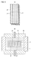
- Powder 7 with the binder or such added thereto is, as shown in FIG. 1(a) , packed in a mold 9.
- the mold 9 is comprised of a die 11 of a cylindrical shape for example, an upper punch 13 and a lower punch 15 both of which fit in an inner hole 11h of the die 11.
- the punches 13, 15 are slidable relative to the inner hole 11h and also establish a proper fit with the inner hole 11h so as to prevent leakage of the powder 7 when being pressurized.
- the mold 9 with the powder 7 packed therein is charged in a proper press machine.
- the upper and lower punches 13, 15 are pressurized by means of rams 17, 19 of the press machine so that the powder 7 packed in the mold 9 is pressurized.
- the powder 7 is as shown in FIG. 1(b) aggregated, thereby obtaining a compressed powder body 21 which does not readily collapse.
- the shape of the compressed powder body 21 can be properly regulated by the shape of the inner hole 11h and the amount of the powder 7, and is, for example, of a quadrangular prism shape with dimensions of 15 (D) x 8(W) x 100(L) mm 3 . Of course, other various shapes such as a hexagonal prism shape are possible.
- This step is reciprocally carried out and then a plurality of compressed powder bodies 21 is obtained.
- a process to apply isostatic pressure such as cold isostatic press (CIP) is individually carried out on the compressed powder bodies 21. More specifically, each compressed powder body 21 is, as shown in FIG. 2(a) , individually sealed in a thin rubber bag 23. Any proper elastic material instead of rubber may be utilized.
- the compressed powder body 21 along with the bag 23 in this state is, as shown in FIG. 2(b) , immersed in liquid L in a pressure vessel 25 and then isostatically pressurized. This step improves uniformity of density of the compressed powder body 21 and accordingly improves uniformity of a final product.
- the isostatic pressure in the preliminary isostatic pressure step is lower than a pressure in the step of pressurizing the powder 7.
- Such isostatic pressure is beneficial in prevention of deformation of the compressed powder body 21.
- FIG. 3(a) illustrates one of such examples.
- a mode in which compressed powder bodies 21 having a common length are arranged in parallel may be applied, and also they may contain short compressed powder bodies 21 arranged in series.
- the number of the compressed powder bodies 21 can be increased or reduced as necessary.
- they are brought into a state in which ends thereof are made flush with each other as shown in FIG. 3(a) .
- the plurality of compressed powder bodies 21 is sealed in a bag 27 of a rubber or such, and CIP is as shown in FIG. 3(b) carried out thereon.
- hot isostatic press instead of CIP may be applied.
- HIP hot isostatic press
- a heating condition may be set up so that presintering in the compressed powder bodies 21 properly progresses.
- it may be modified so that a sintering step as described later is simultaneously carried out in HIP.
- isostatic pressure by means of the liquid L in the pressure vessel 25
- the plurality of compressed powder bodies 21 is joined together to obtain a joined body 29 as shown in FIG. 4 .
- the isostatic pressure applied on the plurality of compressed powder bodies 21 is identical to pressure in the step of pressurizing the powder 7.
- Such isostatic pressure is beneficial in promoting joining while preventing deformation of the compressed powder bodies 21.
- the joined body 29 is composed of the plurality of compressed powder bodies 21, the compressed powder bodies 21 are mutually joined and thus the joined body 29 does not readily collapse. As keeping this state, the joined body 29 is as shown in FIG. 5 introduced into a heating furnace 31.
- the atmosphere in the heating furnace 31 is set to be non-oxidative.
- a vacuum below 10 -1 Pa and inert atmospheres by inert gases such as nitrogen or argon can be exemplified.
- the heating furnace 31 is further comprised of a proper heating means 33 such as a carbon heater.
- a proper heating means 33 such as a carbon heater.
- joining and sintering may be simultaneously carried out, as described already, by means of HIP, instead of independent execution of the step of sintering and the step of joining.
- the sintered body After finishing the sintering, the sintered body is properly cooled so as to prevent excessive thermal shock thereon. The sintered body is thereafter taken out of the heating furnace 31.
- the sintered body as shown in FIG. 6 can be utilized as an electrode 1 for a discharge surface treatment.
- FIG. 6 illustrates an example in that a subject body 3 of the surface treatment is a rotor blade of a gas turbine engine and an area of the subject is a tip end of the rotor blade.
- an electric spark machine 41 is comprised of an electrically conductive bed 43, a machining bath 45 capable of pooling a machining liquid F, a power supply 47, and a head 49 to which the electrode is fixed.
- the head 49 is capable of going up and down by means of any proper means, and further the electric spark machine 41 may be comprised of a servomotor 51 for making the head go up and down.
- a non-conductive machining liquid F such as oil is pooled, and a tip end of the electrode 1 and the subject body 3 are both immersed in the machining liquid F.
- the discharge surface treatment can be carried out.
- the subject body 3 is fixed on the bed 43 so as to allow current conduction therethrough. Both poles of the power supply 47 are respective electrically connected to the bed 43 and the head 49, thereby allowing current conduction from the power supply 47 to the electrode 1 and the subject body 3.
- the electrode 1 is brought close to a subject area of the subject body 3. Then electricity is supplied from the power supply 47 and discharge is thereby generated between the electrode 1 and the subject body 3. Preferably the supplied electricity is made intermittent so that the discharge is generated in a pulsed manner.
- the electrode 1 is porous as described above, it undergoes consumption preferentially relative to the subject body 3, thereby the material constituting the electrode 1, as a coating, adheres to the subject area on the subject body 3.
- its reaction product may be the coating 5.
- Part of energy of the discharge is thrown into the subject area of the subject body 3 so as to cause local fusion and therefore bonding between the coating 5 and the subject body 3 is firm. Further, as a part in the subject body 3 in which the energy of the discharge is thrown is localized and superficial, the subject body 3 hardly experiences thermal damage and deformation.
- FIG. 6(b) illustrates a state after repeating such processes several times.
- FIG. 6(c) illustrates such an exmple.
- each compressed powder 21 is accurate in shape and is further uniform in density.
- the electrode 1 is formed by joining and sintering them, these properties are reflected in the resultant product, thereby the electrode 1 has high accuracy in shape and high uniformity.
- a relatively large-sized electrode is not formed by the present method but formed directly by molding and sintering, it results in non-uniformity in density from its periphery toward its center generates and often deformation by shrinkage around its center.
- Such a sintered body is not suitable for an electrode for a discharge surface treatment in view of its shape and non-uniformity.
- the present embodiment is prominently advantageous in accuracy in shape and-uniformity.
- an electrode with accuracy in shape and uniformity can be constituted even though it is large-sized. Scalable expansion of its dimensions is enabled while accuracy in shape and uniformity are retained at high levels.
- the present embodiment enables uniform surface treatment on a large area. As it is based on a discharge surface treatment, one can still enjoy an advantage in that a surface-treated area is limited within a area opposed to the electrode.
- An art which enables large area surface treatment is provided while it is based on a discharge surface treatment.
Landscapes
- Mechanical Engineering (AREA)
- Engineering & Computer Science (AREA)
- Chemical & Material Sciences (AREA)
- Manufacturing & Machinery (AREA)
- Materials Engineering (AREA)
- Metallurgy (AREA)
- Organic Chemistry (AREA)
- Physics & Mathematics (AREA)
- Fluid Mechanics (AREA)
- Chemical Kinetics & Catalysis (AREA)
- Composite Materials (AREA)
- Powder Metallurgy (AREA)
- Other Surface Treatments For Metallic Materials (AREA)
- Press-Shaping Or Shaping Using Conveyers (AREA)
- Battery Electrode And Active Subsutance (AREA)
Abstract
Description
- The present invention relates to an electrode for utilizing electric discharge to form a coating or a deposition on a subject, and a method for forming a coating or a deposition therewith.
- To bring a non-consumable electrode close to a subject body in oil or in the air and generate electric discharge therebetween, the subject body can be machined. This art is in general referred to as electric spark machining, and is known to enable precise machining and formation of complex shapes. Under certain conditions, such as those where a consumable electrode such as a compressed powder body is used instead of a non-consumable electrode, or any, consumption of the electrode preferentially occurs instead of machining the subject body. A material constituting the electrode or its reaction result at this time covers an area on the subject body opposed to the electrode, thereby enabling surface treatment of the subject body. A related art is disclosed in an International Publication
WO 99/58744 - As being understood from the above description, the subject of a discharge surface treatment is essentially limited to an area opposed to the electrode. This property is one of advantages of the discharge surface treatment as it enables localized surface treatment. On the other hand, in a case where surface treatment should be carried out on a large area with uniformity, it could be a disadvantage.
- The present invention has been achieved in view of the aforementioned problem and its purpose is to provide an art which enables large area surface treatment while it is based on discharge surface treatment.
- According to a first aspect of the present invention, a production method of an electrode for a discharge surface treatment is comprised of steps of: packing and pressurizing powder including an electrically conductive material in a mold so as to obtain a plurality of compressed powder bodies; joining the plurality of compressed powder bodies together by arranging the plurality of compressed powder bodies to be mutually in close contact and applying isostatic pressure on the arranged compressed powder bodies; and sintering the joined compressed powder bodies so as to obtain a sintered body.
- Preferably, the production method further includes a step of preliminary isostatic pressure, wherein isostatic pressure is applied to each compressed powder body individually. More preferably, in the production method, the isostatic pressure in the step of joining is identical to pressure in the step of packing and pressurizing, and a second isostatic pressure in the step of preliminary isostatic pressure is lower than the isostatic pressure in the step of joining.
- According to a second aspect of the present invention, a surface treatment method of a subject body is comprised of steps of: packing and pressurizing powder including an electrically conductive material in a mold so as to obtain a plurality of compressed powder bodies; joining the plurality of compressed powder bodies together by arranging the plurality of compressed powder bodies to be mutually in close contact and applying isostatic pressure on the arranged compressed powder bodies; sintering the joined compressed powder bodies so as to obtain a sintered body; and carrying out a discharge surface treatment by bringing the sintered body close to a subject body and generating electric discharge.
- Preferably, the surface treatment method further includes a step of preliminary isostatic pressure, wherein isostatic pressure is applied to each compressed powder body individually. More preferably, in the surface treatment method, the isostatic pressure in the step of joining is identical to pressure in the step of packing and pressurizing, and a second isostatic pressure in the step of preliminary isostatic pressure is lower than the isostatic pressure in the step of joining.
-
- [
FIG. 1] FIG. 1 is a drawing explaining a production method of an electrode in accordance with an embodiment of the present invention, which illustrates a step of obtaining a compressed powder body by pressurizing. - [
FIG. 2] FIG. 2 is a drawing explaining a step in the production method in which isostatic pressure is applied to each compressed powder body individually. - [
FIG. 3] FIG. 3 is a drawing explaining a step in the production method in which a plurality of compressed powder bodies is arranged and then joined together. - [
FIG. 4] FIG. 4 is a perspective view illustrating an example of a plurality of compressed powder bodies arranged to be mutually in close contact. - [
FIG. 5] FIG. 5 is a schematic drawing showing a step of sintering in the production method. - [
FIG. 6] FIG. 6 is a schematic drawing showing a discharge surface treatment method in accordance with the present embodiment. - [
FIG. 7] FIG. 7 is a schematic drawing showing a mode of the discharge surface treatment method, in which an electrode and a subject body are installed in an electric spark machine. - Throughout the present specification and the appended claims, the term "discharge surface treatment" is defined and used as an act of utilizing electric discharge in an electric spark machine to consume an electrode instead of machining a subject body, and adhering a material constituting the electrode, or a reaction product between the material constituting the electrode and a machining liquid or a machining gas, onto the subject body as a coating.
- An embodiment of the present invention will be described hereinafter with reference to the appended drawings.
- In the present embodiment, first a consumable electrode for a discharge surface treatment is produced.
- As a material for the consumable electrode, electrically conductive powder is preferable. The electrically conductive powder may, as a whole, consist of any metal or any semiconductor substance, or alternatively a mixture of any metal or a semiconductor substance and the other substance such as a proper ceramic. Which to choose is determined in accordance with properties required for a coating to be formed on a subject body.
- Preferably a binder is added to the powder and then appropriately mixed thereto. As examples of the binder, paraffin, carnauba wax, polypropylene, polyethylene, acrylic resin, methacrylic resin, and acetal resins can be exemplified, however, any substance which helps loose bonding among powder particles and does not leave undesirable residual substances after sintering may be applicable.
-
Powder 7 with the binder or such added thereto is, as shown inFIG. 1(a) , packed in amold 9. Themold 9 is comprised of adie 11 of a cylindrical shape for example, anupper punch 13 and alower punch 15 both of which fit in aninner hole 11h of the die 11. Thepunches inner hole 11h and also establish a proper fit with theinner hole 11h so as to prevent leakage of thepowder 7 when being pressurized. - The
mold 9 with thepowder 7 packed therein is charged in a proper press machine. The upper andlower punches rams powder 7 packed in themold 9 is pressurized. By this pressurizing, thepowder 7 is as shown inFIG. 1(b) aggregated, thereby obtaining a compressedpowder body 21 which does not readily collapse. The shape of thecompressed powder body 21 can be properly regulated by the shape of theinner hole 11h and the amount of thepowder 7, and is, for example, of a quadrangular prism shape with dimensions of 15 (D) x 8(W) x 100(L) mm3. Of course, other various shapes such as a hexagonal prism shape are possible. This step is reciprocally carried out and then a plurality ofcompressed powder bodies 21 is obtained. - Preferably, preliminarily before subsequent steps, a process to apply isostatic pressure, such as cold isostatic press (CIP), is individually carried out on the compressed
powder bodies 21. More specifically, eachcompressed powder body 21 is, as shown inFIG. 2(a) , individually sealed in athin rubber bag 23. Any proper elastic material instead of rubber may be utilized. Thecompressed powder body 21 along with thebag 23 in this state is, as shown inFIG. 2(b) , immersed in liquid L in apressure vessel 25 and then isostatically pressurized. This step improves uniformity of density of the compressedpowder body 21 and accordingly improves uniformity of a final product. - Preferably the isostatic pressure in the preliminary isostatic pressure step is lower than a pressure in the step of pressurizing the
powder 7. Such isostatic pressure is beneficial in prevention of deformation of thecompressed powder body 21. - Next the
compressed powder bodies 21 are arranged to be mutually in close contact.FIG. 3(a) illustrates one of such examples. A mode in whichcompressed powder bodies 21 having a common length are arranged in parallel may be applied, and also they may contain shortcompressed powder bodies 21 arranged in series. The number of thecompressed powder bodies 21 can be increased or reduced as necessary. Preferably, they are brought into a state in which ends thereof are made flush with each other as shown inFIG. 3(a) . - The plurality of
compressed powder bodies 21 is sealed in abag 27 of a rubber or such, and CIP is as shown inFIG. 3(b) carried out thereon. Alternatively, hot isostatic press (HIP) instead of CIP may be applied. In a case of applying HIP, a heating condition may be set up so that presintering in the compressedpowder bodies 21 properly progresses. Alternatively it may be modified so that a sintering step as described later is simultaneously carried out in HIP. By applying isostatic pressure by means of the liquid L in thepressure vessel 25, the plurality ofcompressed powder bodies 21 is joined together to obtain a joinedbody 29 as shown inFIG. 4 . - Preferably, the isostatic pressure applied on the plurality of
compressed powder bodies 21 is identical to pressure in the step of pressurizing thepowder 7. Such isostatic pressure is beneficial in promoting joining while preventing deformation of thecompressed powder bodies 21. - While the joined
body 29 is composed of the plurality ofcompressed powder bodies 21, thecompressed powder bodies 21 are mutually joined and thus the joinedbody 29 does not readily collapse. As keeping this state, the joinedbody 29 is as shown inFIG. 5 introduced into aheating furnace 31. - As the
heating furnace 31, any furnace having ability of atmosphere control is preferable for the purpose of preventing oxidation. Preferably the atmosphere in theheating furnace 31 is set to be non-oxidative. By way of example of a non-oxidative atmosphere, a vacuum below 10-1 Pa and inert atmospheres by inert gases such as nitrogen or argon can be exemplified. - The
heating furnace 31 is further comprised of a proper heating means 33 such as a carbon heater. By heating the joinedbody 29 by means of the heating means 33, sintering progresses. In regard to the heating temperature, higher temperatures are advantageous in view of promotion of sintering, however, temperatures sufficiently lower than a melting point of the material constituting thepower 7 are preferable in view of preventing a phenomena in that the electrode becomes hardly consumed as sintering overly progresses. Thus, as the heating temperature, 0.5 - 0.8 Tm can be exemplified where Tm (degrees C) is a melting point of the material constituting thepowder 7. - As sintering progresses, additives such as the binder contained in the
compressed powder bodies 21 are evaporated and then disappear, and further firm bonds among the particles in the powder appear. Moreover also among the plurality ofcompressed powder bodies 21, firm bonds appear. The sintered body as a result becomes a single solid as a whole. To utilize it as an electrode for a discharge surface treatment, sintering should be stayed at a stage where openings among the particles do not disappear. According to the aforementioned process, in considerable cases, the openings among the particles do not appear without taking any particular measures, thereby giving a porous sintered body. - Meanwhile joining and sintering may be simultaneously carried out, as described already, by means of HIP, instead of independent execution of the step of sintering and the step of joining.
- After finishing the sintering, the sintered body is properly cooled so as to prevent excessive thermal shock thereon. The sintered body is thereafter taken out of the
heating furnace 31. The sintered body as shown inFIG. 6 can be utilized as anelectrode 1 for a discharge surface treatment. - A discharge surface treatment with using the
electrode 1 formed of the sintered body as produced in a way as described above will be described with reference toFIGs. 6 and7 hereinafter. While the discharge surface treatment will be applicable to various products,FIG. 6 illustrates an example in that asubject body 3 of the surface treatment is a rotor blade of a gas turbine engine and an area of the subject is a tip end of the rotor blade. - Referring to
FIG. 7 , anelectric spark machine 41 is comprised of an electricallyconductive bed 43, amachining bath 45 capable of pooling a machining liquid F, apower supply 47, and ahead 49 to which the electrode is fixed. Thehead 49 is capable of going up and down by means of any proper means, and further theelectric spark machine 41 may be comprised of aservomotor 51 for making the head go up and down. In themachining bath 45, a non-conductive machining liquid F such as oil is pooled, and a tip end of theelectrode 1 and thesubject body 3 are both immersed in the machining liquid F. Alternatively, in the air or any gas instead of the liquid F, the discharge surface treatment can be carried out. Thesubject body 3 is fixed on thebed 43 so as to allow current conduction therethrough. Both poles of thepower supply 47 are respective electrically connected to thebed 43 and thehead 49, thereby allowing current conduction from thepower supply 47 to theelectrode 1 and thesubject body 3. - In the
electric spark machine 41 as described above, theelectrode 1 is brought close to a subject area of thesubject body 3. Then electricity is supplied from thepower supply 47 and discharge is thereby generated between theelectrode 1 and thesubject body 3. Preferably the supplied electricity is made intermittent so that the discharge is generated in a pulsed manner. As theelectrode 1 is porous as described above, it undergoes consumption preferentially relative to thesubject body 3, thereby the material constituting theelectrode 1, as a coating, adheres to the subject area on thesubject body 3. Alternatively, by properly selecting the material constituting theelectrode 1 and the machining liquid F, its reaction product may be thecoating 5. Part of energy of the discharge is thrown into the subject area of thesubject body 3 so as to cause local fusion and therefore bonding between thecoating 5 and thesubject body 3 is firm. Further, as a part in thesubject body 3 in which the energy of the discharge is thrown is localized and superficial, thesubject body 3 hardly experiences thermal damage and deformation. - As the
electrode 1 is consumed, adepression 1t as shown inFIG. 6(b) develops on the lower end of theelectrode 1. Thedepression 1t has a shape corresponding to the subject area of thesubject body 3. When such consumption grows up to a considerable level, it is preferable to slightly move theelectrode 1 or thesubject body 3 so as to have a fresh surface of theelectrode 1 opposed to the subject area.FIG. 6(b) illustrates a state after repeating such processes several times. Alternatively, instead of slightly moving theelectrode 1 or thesubject body 3, it may be preferable to flip it horizontally.FIG. 6(c) illustrates such an exmple. - According to the present embodiment, as plural
compressed powder bodies 21 are individually formed, eachcompressed powder 21 is accurate in shape and is further uniform in density. As theelectrode 1 is formed by joining and sintering them, these properties are reflected in the resultant product, thereby theelectrode 1 has high accuracy in shape and high uniformity. In contrast, in accordance with studies by the present inventors, when a relatively large-sized electrode is not formed by the present method but formed directly by molding and sintering, it results in non-uniformity in density from its periphery toward its center generates and often deformation by shrinkage around its center. Such a sintered body is not suitable for an electrode for a discharge surface treatment in view of its shape and non-uniformity. As compared with such a situation, the present embodiment is prominently advantageous in accuracy in shape and-uniformity. - According to the present embodiment, an electrode with accuracy in shape and uniformity can be constituted even though it is large-sized. Scalable expansion of its dimensions is enabled while accuracy in shape and uniformity are retained at high levels. The present embodiment enables uniform surface treatment on a large area. As it is based on a discharge surface treatment, one can still enjoy an advantage in that a surface-treated area is limited within a area opposed to the electrode.
- Although the invention has been described above by reference to certain embodiments of the invention, the invention is not limited to the embodiments described above. Modifications and variations of the embodiments described above will occur to those skilled in the art, in light of the above teachings.
- An art which enables large area surface treatment is provided while it is based on a discharge surface treatment.
Claims (7)
- A production method of an electrode for a discharge surface treatment comprising the steps of:packing and pressurizing powder including an electrically conductive material in a mold so as to obtain a plurality of compressed powder bodies;joining the plurality of compressed powder bodies together by arranging the plurality of compressed powder bodies to be mutually in close contact and applying isostatic pressure on the arranged compressed powder bodies; andsintering the joined compressed powder bodies so as to obtain a sintered body.
- The production method of claim 1, further comprising the step of preliminary isostatic pressure, wherein isostatic pressure is applied to each compressed powder body individually.
- The production method of claim 2, wherein the isostatic pressure in the step of joining is identical to pressure in the step of packing and pressurizing, and a second isostatic pressure in the step of preliminary isostatic pressure is lower than the isostatic pressure in the step of joining.
- An electrode for a discharge surface treatment produced by the production method of claim 1.
- A surface treatment method of a subject body, comprising the steps of:packing and pressurizing powder including an electrically conductive material in a mold so as to obtain a plurality of compressed powder bodies;joining the plurality of compressed powder bodies together by arranging the plurality of compressed powder bodies to be mutually in close contact and applying isostatic pressure on the arranged compressed powder bodies;sintering the joined compressed powder bodies so as to obtain a sintered body; andcarrying out a discharge surface treatment by bringing the sintered body close to a subject body and generating electric discharge.
- The surface treatment method of claim 5, further comprising the step of preliminary isostatic pressure, wherein isostatic pressure is applied to each compressed powder body individually.
- The surface treatment method of claim 6, wherein the isostatic pressure in the step of joining is identical to pressure in the step of packing and pressurizing, and a second isostatic pressure in the step of preliminary isostatic pressure is lower than the isostatic pressure in the step of joining.
Applications Claiming Priority (2)
| Application Number | Priority Date | Filing Date | Title |
|---|---|---|---|
| JP2009035205 | 2009-02-18 | ||
| PCT/JP2010/052191 WO2010095590A1 (en) | 2009-02-18 | 2010-02-15 | Electrode manufacturing method and electric discharge surface treatment used therein |
Publications (3)
| Publication Number | Publication Date |
|---|---|
| EP2399696A1 true EP2399696A1 (en) | 2011-12-28 |
| EP2399696A4 EP2399696A4 (en) | 2013-11-06 |
| EP2399696B1 EP2399696B1 (en) | 2017-09-27 |
Family
ID=42633872
Family Applications (1)
| Application Number | Title | Priority Date | Filing Date |
|---|---|---|---|
| EP10743716.2A Active EP2399696B1 (en) | 2009-02-18 | 2010-02-15 | Electrode manufacturing method and electric discharge surface treatment used therein |
Country Status (6)
| Country | Link |
|---|---|
| US (1) | US20110300311A1 (en) |
| EP (1) | EP2399696B1 (en) |
| JP (1) | JP5344030B2 (en) |
| CN (2) | CN102317011A (en) |
| RU (1) | RU2490095C2 (en) |
| WO (1) | WO2010095590A1 (en) |
Cited By (1)
| Publication number | Priority date | Publication date | Assignee | Title |
|---|---|---|---|---|
| CN110899693A (en) * | 2019-12-09 | 2020-03-24 | 株洲钻石切削刀具股份有限公司 | Forming method and forming device for powder metallurgy part |
Families Citing this family (5)
| Publication number | Priority date | Publication date | Assignee | Title |
|---|---|---|---|---|
| US9284647B2 (en) | 2002-09-24 | 2016-03-15 | Mitsubishi Denki Kabushiki Kaisha | Method for coating sliding surface of high-temperature member, high-temperature member and electrode for electro-discharge surface treatment |
| CN100360712C (en) | 2002-09-24 | 2008-01-09 | 石川岛播磨重工业株式会社 | Method for coating sliding surface of high temperature member, and high temperature member and electrode for electric discharge surface treatment |
| CN1692179B (en) * | 2002-10-09 | 2011-07-13 | 石川岛播磨重工业株式会社 | Rotor and coating method therefor |
| EP2484806A3 (en) * | 2005-03-09 | 2012-11-21 | IHI Corporation | Surface treatment method and repair method |
| CN111014852B (en) * | 2019-12-11 | 2021-02-09 | 深圳大学 | Powder metallurgy composite material electrode and preparation method thereof |
Citations (6)
| Publication number | Priority date | Publication date | Assignee | Title |
|---|---|---|---|---|
| US5774779A (en) * | 1996-11-06 | 1998-06-30 | Materials And Electrochemical Research (Mer) Corporation | Multi-channel structures and processes for making such structures |
| JP2006002188A (en) * | 2004-06-15 | 2006-01-05 | Yasushi Watanabe | Copper-based material and manufacturing method therefor |
| JP2006249462A (en) * | 2005-03-08 | 2006-09-21 | Ishikawajima Harima Heavy Ind Co Ltd | Method for producing electrode, and electrode |
| US20070081916A1 (en) * | 2003-06-04 | 2007-04-12 | Mitsuo Chigasaki | Production of the metallic parts with the alloyed layer containing dispersed compound particles, and the wear-proof parts |
| EP1873276A1 (en) * | 2005-03-09 | 2008-01-02 | IHI Corporation | Surface treatment method and repair method |
| WO2008032359A1 (en) * | 2006-09-11 | 2008-03-20 | Mitsubishi Electric Corporation | Process for producing electrode for electric discharge surface treatment and electrode for electric discharge surface treatment |
Family Cites Families (11)
| Publication number | Priority date | Publication date | Assignee | Title |
|---|---|---|---|---|
| SU745624A1 (en) * | 1977-07-11 | 1980-07-07 | Ждановский металлургический институт | Method of producing powdered electrode materials |
| JPS61193800A (en) * | 1985-02-21 | 1986-08-28 | Kobe Steel Ltd | Production of composite billet |
| SU1625636A1 (en) * | 1989-03-27 | 1991-02-07 | Краматорский Индустриальный Институт | Consumable electrode and method of making the same |
| AT1770U1 (en) * | 1996-12-04 | 1997-11-25 | Miba Sintermetall Ag | METHOD FOR PRODUCING A SINTER MOLDED BODY, IN PARTICULAR A TIMING BELT OR CHAIN WHEEL |
| JPH10296498A (en) * | 1997-04-22 | 1998-11-10 | Toshiba Mach Co Ltd | Manufacture of powder green compact |
| CN1185366C (en) * | 1998-05-13 | 2005-01-19 | 三菱电机株式会社 | Electrode for discharge surface treatment and manufacturing method thereof and discharge surface treatment method and device |
| CN1126628C (en) * | 1999-02-24 | 2003-11-05 | 三菱电机株式会社 | Method and device for discharge surface treatment |
| JP3976991B2 (en) * | 2000-07-12 | 2007-09-19 | 本田技研工業株式会社 | Metal casting wrap |
| US7537808B2 (en) * | 2002-07-30 | 2009-05-26 | Mitsubishi Denki Kabushiki Kaisha | Electrode for electric discharge surface treatment, electric discharge surface treatment method and electric discharge surface treatment apparatus |
| WO2004106587A1 (en) * | 2003-05-29 | 2004-12-09 | Mitsubishi Denki Kabushiki Kaisha | Discharge surface treatment electrode, process for producing discharge surface treatment electrode, discharge surface treatment apparatus and discharge surface treatment method |
| RU2465981C2 (en) * | 2007-07-18 | 2012-11-10 | АйЭйчАй КОРПОРЕЙШН | Method of fabricating electrode for surface electric-discharge processing and electrode for surface electric-discharge processing |
-
2010
- 2010-02-15 EP EP10743716.2A patent/EP2399696B1/en active Active
- 2010-02-15 CN CN2010800079352A patent/CN102317011A/en active Pending
- 2010-02-15 WO PCT/JP2010/052191 patent/WO2010095590A1/en active Application Filing
- 2010-02-15 US US13/201,775 patent/US20110300311A1/en not_active Abandoned
- 2010-02-15 CN CN201410213976.7A patent/CN104107916A/en active Pending
- 2010-02-15 JP JP2011500597A patent/JP5344030B2/en active Active
- 2010-02-15 RU RU2011138003/02A patent/RU2490095C2/en not_active IP Right Cessation
Patent Citations (6)
| Publication number | Priority date | Publication date | Assignee | Title |
|---|---|---|---|---|
| US5774779A (en) * | 1996-11-06 | 1998-06-30 | Materials And Electrochemical Research (Mer) Corporation | Multi-channel structures and processes for making such structures |
| US20070081916A1 (en) * | 2003-06-04 | 2007-04-12 | Mitsuo Chigasaki | Production of the metallic parts with the alloyed layer containing dispersed compound particles, and the wear-proof parts |
| JP2006002188A (en) * | 2004-06-15 | 2006-01-05 | Yasushi Watanabe | Copper-based material and manufacturing method therefor |
| JP2006249462A (en) * | 2005-03-08 | 2006-09-21 | Ishikawajima Harima Heavy Ind Co Ltd | Method for producing electrode, and electrode |
| EP1873276A1 (en) * | 2005-03-09 | 2008-01-02 | IHI Corporation | Surface treatment method and repair method |
| WO2008032359A1 (en) * | 2006-09-11 | 2008-03-20 | Mitsubishi Electric Corporation | Process for producing electrode for electric discharge surface treatment and electrode for electric discharge surface treatment |
Non-Patent Citations (1)
| Title |
|---|
| See also references of WO2010095590A1 * |
Cited By (2)
| Publication number | Priority date | Publication date | Assignee | Title |
|---|---|---|---|---|
| CN110899693A (en) * | 2019-12-09 | 2020-03-24 | 株洲钻石切削刀具股份有限公司 | Forming method and forming device for powder metallurgy part |
| CN110899693B (en) * | 2019-12-09 | 2022-06-14 | 株洲钻石切削刀具股份有限公司 | Forming method and forming device for powder metallurgy part |
Also Published As
| Publication number | Publication date |
|---|---|
| JP5344030B2 (en) | 2013-11-20 |
| WO2010095590A1 (en) | 2010-08-26 |
| RU2011138003A (en) | 2013-03-27 |
| CN104107916A (en) | 2014-10-22 |
| RU2490095C2 (en) | 2013-08-20 |
| US20110300311A1 (en) | 2011-12-08 |
| JPWO2010095590A1 (en) | 2012-08-23 |
| CN102317011A (en) | 2012-01-11 |
| EP2399696B1 (en) | 2017-09-27 |
| EP2399696A4 (en) | 2013-11-06 |
Similar Documents
| Publication | Publication Date | Title |
|---|---|---|
| EP2399696B1 (en) | Electrode manufacturing method and electric discharge surface treatment used therein | |
| CN108558398B (en) | Method for pulse discharge room temperature flash sintering nano ceramic material | |
| US6602561B1 (en) | Electrode for discharge surface treatment and manufacturing method therefor and discharge surface treatment method and device | |
| US10486385B2 (en) | Method for producing metal or ceramic components and components | |
| CN104628393B (en) | A kind of preparation method of high-performance ceramic | |
| CN112789128B (en) | Method for producing a component of complex shape by pressure sintering starting from a preform | |
| CN112789130B (en) | Method for producing a counterform and method for producing a component with a complex shape using such a counterform | |
| JP2019519386A (en) | System and method for machining a workpiece and article machined from the workpiece | |
| CN101670433B (en) | Method for manufacturing metal mold by laser indirect forming | |
| CN113500205B (en) | 3D printing method of bimetallic material | |
| EP1659196B1 (en) | Metal product producing method, metal product, metal component connecting method, and connection structure | |
| EP2564955B1 (en) | Process for production of electrode to be used in discharge surface treatment | |
| CN108262473A (en) | The method of the component of 3D printing composite powder, printing equipped with embedded component and the component and its printer model | |
| KR101099395B1 (en) | Cemented carbide cutting tool using Spark Plasma Sintering and method thereof | |
| US7763349B2 (en) | Protective coating and metal structure | |
| JP4523547B2 (en) | Discharge surface treatment method and discharge surface treatment apparatus | |
| US2581253A (en) | Metallurgy | |
| CN113564660A (en) | Preparation method of titanium alloy high-density micro-arc oxidation film layer | |
| JP2006118033A (en) | Method for producing compositionally gradient cemented carbide | |
| JP2008111198A (en) | Compacting die | |
| RU2593564C1 (en) | Method of hot pressing to obtain combined products of hard alloy and steel of "stud" type | |
| CN117026140A (en) | Compact ceramic coating, preparation method thereof and chemical vapor deposition equipment | |
| US20210162503A1 (en) | Producing a Component by the Application of Particle-Filled Discrete Volume Elements | |
| JP2016108645A (en) | Production device for mold material and method for producing mold material | |
| CN109246939A (en) | A kind of method of increasing material manufacturing copper circuit board pattern |
Legal Events
| Date | Code | Title | Description |
|---|---|---|---|
| PUAI | Public reference made under article 153(3) epc to a published international application that has entered the european phase |
Free format text: ORIGINAL CODE: 0009012 |
|
| 17P | Request for examination filed |
Effective date: 20110914 |
|
| AK | Designated contracting states |
Kind code of ref document: A1 Designated state(s): AT BE BG CH CY CZ DE DK EE ES FI FR GB GR HR HU IE IS IT LI LT LU LV MC MK MT NL NO PL PT RO SE SI SK SM TR |
|
| DAX | Request for extension of the european patent (deleted) | ||
| REG | Reference to a national code |
Ref country code: DE Ref legal event code: R079 Ref document number: 602010045557 Country of ref document: DE Free format text: PREVIOUS MAIN CLASS: B22F0007060000 Ipc: B22F0003040000 |
|
| A4 | Supplementary search report drawn up and despatched |
Effective date: 20131004 |
|
| RIC1 | Information provided on ipc code assigned before grant |
Ipc: B22F 3/04 20060101AFI20130927BHEP Ipc: B23H 1/06 20060101ALI20130927BHEP Ipc: C23C 26/00 20060101ALI20130927BHEP Ipc: B22F 7/06 20060101ALI20130927BHEP Ipc: B22F 3/15 20060101ALI20130927BHEP Ipc: C23C 14/02 20060101ALI20130927BHEP |
|
| 17Q | First examination report despatched |
Effective date: 20151016 |
|
| GRAP | Despatch of communication of intention to grant a patent |
Free format text: ORIGINAL CODE: EPIDOSNIGR1 |
|
| INTG | Intention to grant announced |
Effective date: 20170411 |
|
| GRAS | Grant fee paid |
Free format text: ORIGINAL CODE: EPIDOSNIGR3 |
|
| GRAA | (expected) grant |
Free format text: ORIGINAL CODE: 0009210 |
|
| AK | Designated contracting states |
Kind code of ref document: B1 Designated state(s): AT BE BG CH CY CZ DE DK EE ES FI FR GB GR HR HU IE IS IT LI LT LU LV MC MK MT NL NO PL PT RO SE SI SK SM TR |
|
| REG | Reference to a national code |
Ref country code: GB Ref legal event code: FG4D |
|
| REG | Reference to a national code |
Ref country code: CH Ref legal event code: EP |
|
| REG | Reference to a national code |
Ref country code: AT Ref legal event code: REF Ref document number: 931524 Country of ref document: AT Kind code of ref document: T Effective date: 20171015 |
|
| REG | Reference to a national code |
Ref country code: IE Ref legal event code: FG4D |
|
| REG | Reference to a national code |
Ref country code: DE Ref legal event code: R096 Ref document number: 602010045557 Country of ref document: DE |
|
| REG | Reference to a national code |
Ref country code: FR Ref legal event code: PLFP Year of fee payment: 9 |
|
| PG25 | Lapsed in a contracting state [announced via postgrant information from national office to epo] |
Ref country code: SE Free format text: LAPSE BECAUSE OF FAILURE TO SUBMIT A TRANSLATION OF THE DESCRIPTION OR TO PAY THE FEE WITHIN THE PRESCRIBED TIME-LIMIT Effective date: 20170927 Ref country code: FI Free format text: LAPSE BECAUSE OF FAILURE TO SUBMIT A TRANSLATION OF THE DESCRIPTION OR TO PAY THE FEE WITHIN THE PRESCRIBED TIME-LIMIT Effective date: 20170927 Ref country code: LT Free format text: LAPSE BECAUSE OF FAILURE TO SUBMIT A TRANSLATION OF THE DESCRIPTION OR TO PAY THE FEE WITHIN THE PRESCRIBED TIME-LIMIT Effective date: 20170927 Ref country code: HR Free format text: LAPSE BECAUSE OF FAILURE TO SUBMIT A TRANSLATION OF THE DESCRIPTION OR TO PAY THE FEE WITHIN THE PRESCRIBED TIME-LIMIT Effective date: 20170927 Ref country code: NO Free format text: LAPSE BECAUSE OF FAILURE TO SUBMIT A TRANSLATION OF THE DESCRIPTION OR TO PAY THE FEE WITHIN THE PRESCRIBED TIME-LIMIT Effective date: 20171227 |
|
| REG | Reference to a national code |
Ref country code: NL Ref legal event code: MP Effective date: 20170927 |
|
| REG | Reference to a national code |
Ref country code: LT Ref legal event code: MG4D |
|
| REG | Reference to a national code |
Ref country code: AT Ref legal event code: MK05 Ref document number: 931524 Country of ref document: AT Kind code of ref document: T Effective date: 20170927 |
|
| PG25 | Lapsed in a contracting state [announced via postgrant information from national office to epo] |
Ref country code: LV Free format text: LAPSE BECAUSE OF FAILURE TO SUBMIT A TRANSLATION OF THE DESCRIPTION OR TO PAY THE FEE WITHIN THE PRESCRIBED TIME-LIMIT Effective date: 20170927 Ref country code: GR Free format text: LAPSE BECAUSE OF FAILURE TO SUBMIT A TRANSLATION OF THE DESCRIPTION OR TO PAY THE FEE WITHIN THE PRESCRIBED TIME-LIMIT Effective date: 20171228 Ref country code: BG Free format text: LAPSE BECAUSE OF FAILURE TO SUBMIT A TRANSLATION OF THE DESCRIPTION OR TO PAY THE FEE WITHIN THE PRESCRIBED TIME-LIMIT Effective date: 20171227 |
|
| PG25 | Lapsed in a contracting state [announced via postgrant information from national office to epo] |
Ref country code: NL Free format text: LAPSE BECAUSE OF FAILURE TO SUBMIT A TRANSLATION OF THE DESCRIPTION OR TO PAY THE FEE WITHIN THE PRESCRIBED TIME-LIMIT Effective date: 20170927 |
|
| PG25 | Lapsed in a contracting state [announced via postgrant information from national office to epo] |
Ref country code: ES Free format text: LAPSE BECAUSE OF FAILURE TO SUBMIT A TRANSLATION OF THE DESCRIPTION OR TO PAY THE FEE WITHIN THE PRESCRIBED TIME-LIMIT Effective date: 20170927 Ref country code: RO Free format text: LAPSE BECAUSE OF FAILURE TO SUBMIT A TRANSLATION OF THE DESCRIPTION OR TO PAY THE FEE WITHIN THE PRESCRIBED TIME-LIMIT Effective date: 20170927 Ref country code: CZ Free format text: LAPSE BECAUSE OF FAILURE TO SUBMIT A TRANSLATION OF THE DESCRIPTION OR TO PAY THE FEE WITHIN THE PRESCRIBED TIME-LIMIT Effective date: 20170927 |
|
| PG25 | Lapsed in a contracting state [announced via postgrant information from national office to epo] |
Ref country code: EE Free format text: LAPSE BECAUSE OF FAILURE TO SUBMIT A TRANSLATION OF THE DESCRIPTION OR TO PAY THE FEE WITHIN THE PRESCRIBED TIME-LIMIT Effective date: 20170927 Ref country code: IS Free format text: LAPSE BECAUSE OF FAILURE TO SUBMIT A TRANSLATION OF THE DESCRIPTION OR TO PAY THE FEE WITHIN THE PRESCRIBED TIME-LIMIT Effective date: 20180127 Ref country code: SM Free format text: LAPSE BECAUSE OF FAILURE TO SUBMIT A TRANSLATION OF THE DESCRIPTION OR TO PAY THE FEE WITHIN THE PRESCRIBED TIME-LIMIT Effective date: 20170927 Ref country code: SK Free format text: LAPSE BECAUSE OF FAILURE TO SUBMIT A TRANSLATION OF THE DESCRIPTION OR TO PAY THE FEE WITHIN THE PRESCRIBED TIME-LIMIT Effective date: 20170927 Ref country code: IT Free format text: LAPSE BECAUSE OF FAILURE TO SUBMIT A TRANSLATION OF THE DESCRIPTION OR TO PAY THE FEE WITHIN THE PRESCRIBED TIME-LIMIT Effective date: 20170927 Ref country code: AT Free format text: LAPSE BECAUSE OF FAILURE TO SUBMIT A TRANSLATION OF THE DESCRIPTION OR TO PAY THE FEE WITHIN THE PRESCRIBED TIME-LIMIT Effective date: 20170927 |
|
| REG | Reference to a national code |
Ref country code: DE Ref legal event code: R097 Ref document number: 602010045557 Country of ref document: DE |
|
| PG25 | Lapsed in a contracting state [announced via postgrant information from national office to epo] |
Ref country code: DK Free format text: LAPSE BECAUSE OF FAILURE TO SUBMIT A TRANSLATION OF THE DESCRIPTION OR TO PAY THE FEE WITHIN THE PRESCRIBED TIME-LIMIT Effective date: 20170927 |
|
| PLBE | No opposition filed within time limit |
Free format text: ORIGINAL CODE: 0009261 |
|
| STAA | Information on the status of an ep patent application or granted ep patent |
Free format text: STATUS: NO OPPOSITION FILED WITHIN TIME LIMIT |
|
| PG25 | Lapsed in a contracting state [announced via postgrant information from national office to epo] |
Ref country code: PL Free format text: LAPSE BECAUSE OF FAILURE TO SUBMIT A TRANSLATION OF THE DESCRIPTION OR TO PAY THE FEE WITHIN THE PRESCRIBED TIME-LIMIT Effective date: 20170927 |
|
| 26N | No opposition filed |
Effective date: 20180628 |
|
| REG | Reference to a national code |
Ref country code: CH Ref legal event code: PL |
|
| PG25 | Lapsed in a contracting state [announced via postgrant information from national office to epo] |
Ref country code: MC Free format text: LAPSE BECAUSE OF FAILURE TO SUBMIT A TRANSLATION OF THE DESCRIPTION OR TO PAY THE FEE WITHIN THE PRESCRIBED TIME-LIMIT Effective date: 20170927 |
|
| REG | Reference to a national code |
Ref country code: IE Ref legal event code: MM4A |
|
| REG | Reference to a national code |
Ref country code: BE Ref legal event code: MM Effective date: 20180228 |
|
| PG25 | Lapsed in a contracting state [announced via postgrant information from national office to epo] |
Ref country code: LU Free format text: LAPSE BECAUSE OF NON-PAYMENT OF DUE FEES Effective date: 20180215 Ref country code: CH Free format text: LAPSE BECAUSE OF NON-PAYMENT OF DUE FEES Effective date: 20180228 Ref country code: SI Free format text: LAPSE BECAUSE OF FAILURE TO SUBMIT A TRANSLATION OF THE DESCRIPTION OR TO PAY THE FEE WITHIN THE PRESCRIBED TIME-LIMIT Effective date: 20170927 Ref country code: LI Free format text: LAPSE BECAUSE OF NON-PAYMENT OF DUE FEES Effective date: 20180228 |
|
| PG25 | Lapsed in a contracting state [announced via postgrant information from national office to epo] |
Ref country code: IE Free format text: LAPSE BECAUSE OF NON-PAYMENT OF DUE FEES Effective date: 20180215 |
|
| PG25 | Lapsed in a contracting state [announced via postgrant information from national office to epo] |
Ref country code: BE Free format text: LAPSE BECAUSE OF NON-PAYMENT OF DUE FEES Effective date: 20180228 |
|
| PG25 | Lapsed in a contracting state [announced via postgrant information from national office to epo] |
Ref country code: MT Free format text: LAPSE BECAUSE OF NON-PAYMENT OF DUE FEES Effective date: 20180215 |
|
| PG25 | Lapsed in a contracting state [announced via postgrant information from national office to epo] |
Ref country code: TR Free format text: LAPSE BECAUSE OF FAILURE TO SUBMIT A TRANSLATION OF THE DESCRIPTION OR TO PAY THE FEE WITHIN THE PRESCRIBED TIME-LIMIT Effective date: 20170927 |
|
| PG25 | Lapsed in a contracting state [announced via postgrant information from national office to epo] |
Ref country code: HU Free format text: LAPSE BECAUSE OF FAILURE TO SUBMIT A TRANSLATION OF THE DESCRIPTION OR TO PAY THE FEE WITHIN THE PRESCRIBED TIME-LIMIT; INVALID AB INITIO Effective date: 20100215 Ref country code: PT Free format text: LAPSE BECAUSE OF FAILURE TO SUBMIT A TRANSLATION OF THE DESCRIPTION OR TO PAY THE FEE WITHIN THE PRESCRIBED TIME-LIMIT Effective date: 20170927 |
|
| PG25 | Lapsed in a contracting state [announced via postgrant information from national office to epo] |
Ref country code: CY Free format text: LAPSE BECAUSE OF FAILURE TO SUBMIT A TRANSLATION OF THE DESCRIPTION OR TO PAY THE FEE WITHIN THE PRESCRIBED TIME-LIMIT Effective date: 20170927 Ref country code: MK Free format text: LAPSE BECAUSE OF NON-PAYMENT OF DUE FEES Effective date: 20170927 |
|
| PGFP | Annual fee paid to national office [announced via postgrant information from national office to epo] |
Ref country code: DE Payment date: 20211230 Year of fee payment: 13 |
|
| PGFP | Annual fee paid to national office [announced via postgrant information from national office to epo] |
Ref country code: FR Payment date: 20220118 Year of fee payment: 13 |
|
| REG | Reference to a national code |
Ref country code: DE Ref legal event code: R119 Ref document number: 602010045557 Country of ref document: DE |
|
| PG25 | Lapsed in a contracting state [announced via postgrant information from national office to epo] |
Ref country code: FR Free format text: LAPSE BECAUSE OF NON-PAYMENT OF DUE FEES Effective date: 20230228 Ref country code: DE Free format text: LAPSE BECAUSE OF NON-PAYMENT OF DUE FEES Effective date: 20230901 |
|
| PGFP | Annual fee paid to national office [announced via postgrant information from national office to epo] |
Ref country code: GB Payment date: 20240108 Year of fee payment: 15 |