EP2399010B1 - Vorrichtung zur fluidmengenmessung in antrieben und geräten - Google Patents
Vorrichtung zur fluidmengenmessung in antrieben und geräten Download PDFInfo
- Publication number
- EP2399010B1 EP2399010B1 EP09808934.5A EP09808934A EP2399010B1 EP 2399010 B1 EP2399010 B1 EP 2399010B1 EP 09808934 A EP09808934 A EP 09808934A EP 2399010 B1 EP2399010 B1 EP 2399010B1
- Authority
- EP
- European Patent Office
- Prior art keywords
- drive
- fluid
- measuring
- oil
- sensor
- Prior art date
- Legal status (The legal status is an assumption and is not a legal conclusion. Google has not performed a legal analysis and makes no representation as to the accuracy of the status listed.)
- Not-in-force
Links
- 239000012530 fluid Substances 0.000 title claims description 26
- 238000011156 evaluation Methods 0.000 claims description 24
- 238000001514 detection method Methods 0.000 claims description 5
- 239000000314 lubricant Substances 0.000 claims description 4
- 239000000126 substance Substances 0.000 claims description 4
- 230000001419 dependent effect Effects 0.000 claims description 3
- 239000000203 mixture Substances 0.000 claims description 3
- 230000001133 acceleration Effects 0.000 claims description 2
- 239000003921 oil Substances 0.000 description 36
- 238000005259 measurement Methods 0.000 description 19
- 238000012360 testing method Methods 0.000 description 6
- 238000011161 development Methods 0.000 description 5
- 230000018109 developmental process Effects 0.000 description 5
- 230000002349 favourable effect Effects 0.000 description 4
- 238000000034 method Methods 0.000 description 4
- 230000005540 biological transmission Effects 0.000 description 2
- 238000006243 chemical reaction Methods 0.000 description 2
- 238000013461 design Methods 0.000 description 2
- 238000005516 engineering process Methods 0.000 description 2
- 238000004519 manufacturing process Methods 0.000 description 2
- 239000010705 motor oil Substances 0.000 description 2
- 230000008569 process Effects 0.000 description 2
- 238000012546 transfer Methods 0.000 description 2
- 230000006978 adaptation Effects 0.000 description 1
- 238000004364 calculation method Methods 0.000 description 1
- 230000008859 change Effects 0.000 description 1
- 238000002485 combustion reaction Methods 0.000 description 1
- 238000010276 construction Methods 0.000 description 1
- 239000002826 coolant Substances 0.000 description 1
- 125000004122 cyclic group Chemical group 0.000 description 1
- 230000007613 environmental effect Effects 0.000 description 1
- 238000002474 experimental method Methods 0.000 description 1
- 230000006870 function Effects 0.000 description 1
- 239000010687 lubricating oil Substances 0.000 description 1
- 238000012423 maintenance Methods 0.000 description 1
- 238000012986 modification Methods 0.000 description 1
- 230000004048 modification Effects 0.000 description 1
- 238000003908 quality control method Methods 0.000 description 1
- 238000004171 remote diagnosis Methods 0.000 description 1
- 238000004088 simulation Methods 0.000 description 1
- 239000013589 supplement Substances 0.000 description 1
- 238000010998 test method Methods 0.000 description 1
- 238000002604 ultrasonography Methods 0.000 description 1
Images
Classifications
-
- F—MECHANICAL ENGINEERING; LIGHTING; HEATING; WEAPONS; BLASTING
- F01—MACHINES OR ENGINES IN GENERAL; ENGINE PLANTS IN GENERAL; STEAM ENGINES
- F01M—LUBRICATING OF MACHINES OR ENGINES IN GENERAL; LUBRICATING INTERNAL COMBUSTION ENGINES; CRANKCASE VENTILATING
- F01M11/00—Component parts, details or accessories, not provided for in, or of interest apart from, groups F01M1/00 - F01M9/00
- F01M11/10—Indicating devices; Other safety devices
-
- F—MECHANICAL ENGINEERING; LIGHTING; HEATING; WEAPONS; BLASTING
- F01—MACHINES OR ENGINES IN GENERAL; ENGINE PLANTS IN GENERAL; STEAM ENGINES
- F01M—LUBRICATING OF MACHINES OR ENGINES IN GENERAL; LUBRICATING INTERNAL COMBUSTION ENGINES; CRANKCASE VENTILATING
- F01M11/00—Component parts, details or accessories, not provided for in, or of interest apart from, groups F01M1/00 - F01M9/00
- F01M11/10—Indicating devices; Other safety devices
- F01M11/12—Indicating devices; Other safety devices concerning lubricant level
Definitions
- the invention relates to a device for fluid quantity measurement in drives or devices, with the preamble features of claim 1.
- a device for fluid quantity measurement in drives or devices with the preamble features of claim 1.
- Such a device is known from EP 1 063 498 known.
- a variety of different fluids is used. These include above all lubricants such as engine and transmission oils, but also coolants.
- lubricants such as engine and transmission oils, but also coolants.
- coolants Of particular importance for the low-wear function of the drive is the regular check of the filling quantities of the fluids. For example, engine oil quantities are detected via a level sensor in the oil sump. The detected values are evaluated in accordance with the driving state values of the vehicle, for which purpose, for example, measured values from the control units of the drive or other suitable measuring technology are accessed.
- sensors or cables and the associated measuring technology usually have to be retrofitted or installed by a correspondingly elaborate conversion.
- a relief in the handling offers in Werner et al. 2004 (MTZ 6/2004 65: 482ff .) introduced measuring system in which the mass of the lubricant is determined continuously or discontinuously in a collecting vessel located outside the engine.
- the disadvantage here is the size of the meter.
- the statistical evaluability of the values determined requires a constant flow of the lubricants. Speed or consumption peaks and inclinations of the measuring arrangement (eg in the case of a simulation of a cornering or a downhill or a braking) during the measuring process can thus lead to a falsification of the values.
- the DE 10 2004 001 514 A1 proposes a method and apparatus for determining the lubricating oil content in an exhaust gas mixture. In this case, the oil consumption in the exhaust gas is used to deduce the oil consumption of an engine.
- the object of the present invention is therefore to provide a compact device which enables a precise determination of the fluid consumption, even with an inclined drive. This object is achieved by a device having the features of claim 1. Preferred developments of the invention are the subject of the dependent claims.
- the device according to the invention is preferably a capacitive determination of the operating state-dependent amount of fluids, eg. B. the Schmlerffenmenge made in at least one drive or device, in particular volumetharim ways.
- at least one sensor is provided for detecting the transverse and / or longitudinal inclination of the drive or device with an associated measuring / evaluation unit. The values recorded there are then used in the calculation of the fluid quantity in the drive or the fluid consumption during operation.
- the sensor is designed as an acceleration or angle sensor and can be accommodated in the device in a particularly space-saving manner or can be taken over by a control device or sensor (eg in the brake system) mounted outside the engine.
- a control device or sensor eg in the brake system mounted outside the engine.
- the device In order to be able to carry out a short-term measurement, for example during development and test phases or during maintenance, it is considered favorable if the device is detachably connected to the drive. It proves to be particularly advantageous if the device can be coupled to the drive via an inlet or drain screw for the fluid, in particular an oil drain plug. In order to be able to determine a correlation between the operating parameters of the drive and the fluid quantity or consumption, it is considered favorable if the device is coupled to the drive control, in particular the ignition signal transmitter.
- suitable sensors prove to be advantageous for further increasing the measuring accuracy if the device has at least one additional sensor for detecting physical and / or chemical parameters of the fluid, in particular the pressure, the temperature and / or the chemical composition.
- the determination of the amount of fluid and / or the detection of the lateral and / or longitudinal inclination occur continuously and / or cyclically. For example, in the development or testing phase, continuous acquisition of the values will occur, while during normal operation of the drive, cyclic measurement of the error detection values will occur to warn against Fluidmengenmängeln o. The like. Is sufficient.
- the device preferably has a display and / or evaluation unit, which can be assigned to the storage unit wirelessly or by cable, for the detected values, so that, for example, a readout of the stored values from the storage unit can easily be carried out for remote diagnosis. In this case, it is preferable for the operator to decide whether a continuous or subsequent display and / or evaluation of the detected values is to be carried out.
- the use of the device is crucial. For example, while a continuous output of the values is favorable when used on engine test benches, a subsequent display or evaluation of the values is sufficient for evaluating the parameters of the drive in routine use.
- the device may additionally have a sensor or detector for the distance traveled and / or the operating time, as well as the measurement / evaluation unit may have a GPS or Galileo receiver.
- environmental parameters such as air pressure, humidity, etc. can be detected.
- the device has at least one tub or container for the fluid from the drive or device.
- the device has a plurality of terminals. These connections also make it possible to use one device in parallel or serially with multiple drives or devices simultaneously.
- the use of the device with an internal combustion engine is shown by way of example below. Also conceivable is the use with similar drives, equipment or machinery, such as gearboxes, turbines, hydraulic pumps.
- the output of the oil consumption measurement is the level of the oil in the oil sump of the engine which is set in a certain operating state. This level is passed through a pipe or a hose according to the principle of communicating tubes to the measuring device. There, the level can be measured by the gravimetric or volumetric measuring principle, but also by microwaves, ultrasound or capacitive.
- the device now detects via suitable sensors z. As the engine speed and the oil temperature and the inclination sensors in addition the angular position of the device and / or the oil pan.
- a comparison of the values with the values of a defined operating state can now take place.
- corresponding characteristic curves or characteristic maps are created beforehand. These allow an assignment of the determined output oil level and the amount of oil in the engine. To prevent, that a change in the oil level takes place through the oil introduced into the device, a corresponding compensating oil quantity is added.
- the operating parameters of the drive should be recorded continuously. These include, for example, the determination of the respective speed range, the oil temperature difference in several measurements and read via the sensors angular position (lateral and longitudinal tilt) of the drive or the system comprising this drive.
- the relevant values are recorded via the engine control and / or additional sensors or measuring sensors provided on the drive or the device.
- predetermined operating states can be recorded and tested in various measurements on the basis of predefined characteristic curves and fields. In this case, first the oil level is measured, which is set in the measuring unit before the beginning of the measurement. After or during the driving cycles to be checked, the oil level is measured again. The two oil levels are each assigned an amount of oil. The difference between the measured values results in the oil consumption.
- the respective operating states should also be approached constantly over a defined time. It also records the time and / or distance covered. During the test procedure or the check, the cyclically or continuously recorded values can be displayed directly or after correlation with other parameters via a display.
- the oil or fluid consumption measurement can not only be applied to road vehicles, but is suitable i.a. also for rail vehicles, watercraft, aircraft / aircraft and mobile equipment. Furthermore, the use in the stationary area, u.a. In production machines, machines on test benches, heat engines, etc. possible, and it is important to compare several measurements, to determine the respective amounts of fluid in a simple manner.
- these can be connected to the same or parallel device (s). If in each case the same amount of fluid is present in two devices of the same design, then in the same operating state the same oil level in the device or in the part, for example a trough or a closed container, in which the measurement is carried out must be set. If this is not the case, component tolerances / component damage can be assumed. This can be used, for example, to check whether the same engine oil or the same amount of oil was filled in test benches or vehicles with the same engines.
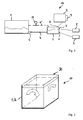
- Fig. 1 shows an embodiment of the device 10 according to the invention for determining the amount of oil or the oil consumption in a drive 1.
- the device 10 is mounted outside of a drive 1 in the embodiment. However, it is also conceivable attachment of the device 10 to or in a transmission, a turbine or other engine, in particular the supplement of the previous oil measuring device with a tilt sensor.
- the device 10 comprises a combined measuring / evaluation unit 2 and a memory unit 9 and is connected via an outlet 6 to the motor.
- a pipe or hose connection 4 may be connected to the oil drain pipe, so that an exchange of oil between the drive 1 and measuring / evaluation unit 2 can take place.
- the measuring / evaluation unit 2 has a container 7, in which a level is set, which corresponds to the level in the drive 1.
- the measuring / evaluation unit 2 is equipped with a level sensor 5, but can be extended to increase the measurement and subsequent evaluation accuracy with other sensors 3, such as sensors 3 for the oil temperature, the oil pressure or the opacity of the oil.
- sensors 3 for the oil temperature, the oil pressure or the opacity of the oil.
- further operating state values from the drive or device control can be used to determine the oil consumption or the fill level.
- the connection to the evaluation unit 2 can be made directly via a hose 4 or indirectly via a container 7.
- a return line 4 ' is connected, in which a compensating vessel 11 may be installed, in particular at higher gas contents in the fluid.
- the measuring / evaluation unit 2 makes it possible to check whether the same oil level in the measuring / evaluation unit 2 can be measured with identically constructed drives 1, the same oil quantities and the same operating states, and serves for quality control and for measuring the production spread. With the illustrated device 10, a conversion of the drive 1 is not necessary.
- the measuring / evaluation unit 2 can directly via an inlet or outlet 6 of the drive 1, z. As an oil drain plug to be connected.
- the connection can also be made via other connections 8, the direct or indirect fluid exchange or signal transfer, such. B. the transfer of pressure, allow.
- the possibility of measuring and simultaneously evaluating the measured values makes the measuring / evaluation unit 2 in many - also not equipped with appropriate sensors - drives 1 can be used and is also suitable for use in workshops or for mobile measurements.
- Fig. 2 shows the attached here to a motor measuring / evaluation unit 2 of the device 10 according to the invention, with angle sensors 30 for determining the transverse and / or longitudinal inclination of the drive to be measured 1 (see. Fig. 1 ) is equipped.
- the angle sensors 30, as well as other usable with the device 10 sensors 3 (see. Fig. 1 ) can, for example via a pipe or hose connection 4 (see. Fig. 1 ) are connected to terminals 8 on the device 10 or integrated directly into it.
- the angle sensors 30 detect continuously or cyclically the transverse or longitudinal inclination of the drive to be measured 1 or device (gear, pump, etc.), as indicated by the two arrows and thus allow the direct consideration of the inclination values in the measurement and evaluation of fluid quantities.
Landscapes
- Engineering & Computer Science (AREA)
- Mechanical Engineering (AREA)
- General Engineering & Computer Science (AREA)
- Lubrication Details And Ventilation Of Internal Combustion Engines (AREA)
- Measuring Fluid Pressure (AREA)
Description
- Die Erfindung betrifft eine Vorrichtung zur Fluidmengenmessung in Antrieben bzw. Geräten, mit den oberbegrifflichen Merkmalen des Anspruchs 1. Eine solche Vorrichtung ist aus der
EP 1 063 498 bekannt. - In den verschiedenen Teilen eines Antriebs oder eines Gerätes wird eine Vielzahl unterschiedlicher Fluide eingesetzt. Hierzu zählen vor allem Schmiermittel wie Motor- und Getriebeöle, aber auch Kühlmittel. Besondere Bedeutung für die verschleißarme Funktion des Antriebs kommt dabei der regelmäßigen Überprüfung der Füllmengen der Fluide zu. So werden beispielsweise Motorölmengen über einen Füllstandssensor in der Ölwanne erfasst. Die erfassten Werte werden entsprechend den Fahrzustandswerten des Fahrzeugs ausgewertet, wobei hierzu beispielsweise auf Messwerte aus den Steuergeräten des Antriebs oder sonstige geeignete Messtechnik zugegriffen wird. Für die Erfassung der jeweiligen Füllmengen, der auch eine besondere Bedeutung bei der Entwicklung und Erprobung von Antrieben zukommt, müssen bisher in der Regel durch einen entsprechend aufwändigen Umbau Sensoren, Kabeln und die zugehörige Messtechnik nachgerüstet bzw. angebracht werden.
- Eine Erleichterung in der Handhabung bietet die in Werner et al. 2004 (MTZ 6/2004 65: 482ff.) vorgestellte Messanlage, bei der die Masse des Schmiermittels in einem außerhalb des Motors befindlichen Auffanggefäß kontinuierlich oder diskontinuierlich ermittelt wird. Nachteilig hierbei ist jedoch die Größe des Messgerätes. Zudem setzt die statistische Auswertbarkeit der ermittelten Werte einen konstanten Fluss der Schmiermittel voraus. Drehzahl- oder Verbrauchsspitzen sowie Neigungen der Messanordnung (z. B. bei einer Simulation einer Kurvenfahrt oder einer Bergabfahrt oder einer Bremsung) während des Messvorganges können somit zu einer Verfälschung der Werte führen. Die
DE 10 2004 001 514 A1 schlägt ein Verfahren und eine Vorrichtung zur Bestimmung des Schmierölgehalts in einem Abgasgemisch vor. Hierbei wird aus der Ölemission im Abgas auf den Ölverbrauch eines Motors rückgeschlossen. - Nachteilig an den vorgeschlagenen Vorrichtungen und Verfahren ist neben deren Bauaufwand, dass die gezeigten Vorrichtungen einen erheblichen Umbau am zu vermessenden Antrieb voraussetzen und eine Neigung des Antriebs bzw. Geräts während des Messvorganges unberücksichtigt bleibt.
- Aufgabe der vorliegenden Erfindung ist es daher, eine kompakte Vorrichtung zur Verfügung zu stellen, die eine präzise Bestimmung des Fluidverbrauchs auch bei geneigtem Antrieb ermöglicht. Diese Aufgabe wird gelöst durch eine Vorrichtung mit den Merkmalen des Anspruchs 1. Bevorzugte Weiterbildungen der Erfindung sind Gegenstand der abhängigen Ansprüche.
- Mit der erfindungsgemäßen Vorrichtung wird bevorzugt eine kapazitive Ermittlung der betriebszustandsabhängigen Menge von Fluiden, z. B. der Schmlermittelmenge in wenigstens einem Antrieb oder Gerät vorgenommen, insbesondere auf volumetrischem Wege. Um diese Ermittlung auch bei einer Neigung des Antriebes durchführen zu können, ist wenigstens ein Sensor zur Erfassung der Querund/oder Längsneigung des Antriebs bzw. Geräts mit einer zugeordneten Mess-/Auswerteeinheit vorgesehen. Die dort erfassten Werte werden anschließend bei der Berechnung der Fluidmenge im Antrieb bzw. des Fluidverbrauchs während des Betriebs herangezogen. Bevorzugt ist der Sensor als Beschleunigungs- oder Winkelsensor ausgebildet und kann besonders platzsparend in der Vorrichtung untergebracht werden oder von einem außerhalb des Motors angebrachten Steuergerät bzw. Sensor (z. B. im Bremssystem) übernommen werden. Für die permanente Erfassung der Verbrauchswerte, beispielsweise zur Anpassung des Motormanagements, empfiehlt es sich, die Vorrichtung (oder Teile davon) dauerhaft mit dem Antrieb zu verbinden oder in diesen einzubauen.
- Um eine kurzzeitige Messung, beispielsweise in Entwicklungs- und Erprobungsphasen oder bei der Wartung durchführen zu können, wird es als günstig angesehen, wenn die Vorrichtung lösbar mit dem Antrieb verbunden ist. Als besonders vorteilhaft erweist es sich dabei, wenn die Vorrichtung über eine Einlass- oder Ablassschraube für das Fluid, insbesondere eine Ölablassschraube, an den Antrieb koppelbar ist. Um eine Korrelation zwischen den Betriebsparametern des Antriebs und der Fluidmenge bzw. dem -verbrauch feststellen zu können, wird es als günstig angesehen, wenn die Vorrichtung mit der Antriebssteuerung, insbesondere dem Zündsignalgeber gekoppelt ist.
- Neben der Erfassung der Quer- und/oder Längsneigung des Antriebs Ober geeignete Sensoren erweist es sich zur weiteren Erhöhung der Messgenauigkeit als vorteilhaft, wenn die Vorrichtung wenigstens einen zusätzlichen Sensor zur Erfassung physikalischer und/oder chemischer Parameter des Fluides, insbesondere des Druckes, der Temperatur und/oder der chemischen Zusammensetzung aufweist. In Abhängigkeit vom Versuchsdesign bzw. des Erfassungsziels ist es empfehlenswert, dass die Ermittlung der Fluidmenge und/oder die Erfassung der Quer- und/oder Längsneigung kontinuierlich und/oder zyklisch erfolgt. So wird beispielsweise in der Entwicklungs- oder Erprobungsphase eine kontinuierliche Erfassung der Werte erfolgen, während beim normalen Betrieb des Antriebs eine zyklische Messung der Werte zur Erkennung von Fehlern oder zur Warnung vor Fluidmengenmängeln o. dgl. ausreicht.
- Um eine nachträgliche Auswertung der erfassten Werte durchführen zu können, wird es als günstig erachtet, wenn in der Vorrichtung eine Speichereinheit für die erfassten Werte vorgesehen ist. Bevorzugt weist die Vorrichtung eine der Speichereinheit kabellos oder kabelgebunden zuordenbare Anzeige- und/oder Auswerteeinheit für die erfassten Werte auf, so dass beispielsweise zur Ferndiagnose ein Auslesen der gespeicherten Werte aus der Speichereinheit problemlos durchgeführt werden kann. Bevorzugt wird dem Bediener dabei die Wahl überlassen, ob eine kontinuierliche oder nachträgliche Anzeige und/oder Auswertung der erfassten Werte durchgeführt werden soll. Auch hier ist der Einsatz der Vorrichtung ausschlaggebend. Während beispielsweise bei der Verwendung auf Motorprüfständen eine kontinuierliche Ausgabe der Werte günstig ist, genügt für die Auswertung der Parameter des Antriebs im routinemäßigen Einsatz eine nachträgliche Anzeige bzw. Auswertung der Werte. Zudem kann die Vorrichtung zusätzlich einen Sensor bzw. Detektor für die zurückgelegte Wegstrecke und/oder die Betriebsdauer aufweisen, ebenso kann die Mess-/Auswerteeinheit einen GPS- oder Galileo-Empfänger besitzen. Zudem können auch Umweltparameter wie Luftdruck, Luftfeuchtigkeit usw. detektiert werden.
- Zur vereinfachten Messung der Parameter verfügt die Vorrichtung über wenigstens eine Wanne oder einen Behälter für das Fluid aus dem Antrieb bzw. Gerät. Um mit einer Vielzahl von zusätzlichen Mess- und/oder Erfassungsgeräten verbindbar zu sein, wird es als vorteilhaft angesehen, wenn die Vorrichtung eine Vielzahl von Anschlüssen aufweist. Über diese Anschlüsse ist es zudem auch möglich, eine Vorrichtung parallel oder seriell mit mehreren Antrieben oder Geräten simultan zu verwenden.
- Nachfolgend wird exemplarisch die Verwendung der Vorrichtung mit einem Verbrennungsmotor dargestellt. Denkbar ist auch die Verwendung mit ähnlichen Antrieben, Geräten oder Maschinen, beispielsweise Getrieben, Turbinen, Hydraulikpumpen. Ausgang der Ölverbrauchsmessung ist die sich in einem bestimmten Betriebszustand einstellende Füllstandshöhe des Öls in der Ölwanne des Motors. Diese Füllstandshöhe wird über ein Rohr oder einen Schlauch nach dem Prinzip der kommunizierenden Röhren an die Messvorrichtung weitergegeben. Dort kann der Füllstand nach dem gravimetrischen oder volumetrischen Messprinzip, aber auch per Mikrowellen, Ultraschall oder kapazitiv gemessen werden. Die Vorrichtung erfasst nun über geeignete Sensoren z. B. die Motordrehzahl und die Öltemperatur sowie über die Neigungssensoren zusätzlich die Winkellage der Vorrichtung und/oder der Ölwanne. Gegebenenfalls kann nun ein Abgleich der Werte mit den Werten eines definierten Betriebszustandes erfolgen. Um die Messungen durchführen zu können, werden zuvor entsprechende Kennlinien oder auch Kennfelder erstellt. Diese erlauben eine Zuordnung des ermittelten Ausgangsölniveaus und der Ölmenge im Motor. Um zu verhindern, dass durch das in die Vorrichtung eingeleitete Öl eine Änderung des Ölstandes erfolgt, wird eine entsprechende Ausgleichsölmenge nachgefüllt.
- Um verschiedene Messungen vergleichen zu können, sollten die Betriebsparameter des Antriebs kontinuierlich erfasst werden. Hierzu gehört beispielsweise auch die Ermittlung des jeweiligen Drehzahlbereichs, die Öltemperaturdifferenz bei mehreren Messungen sowie die über die Sensoren ausgelesene Winkellage (Quer- und Längsneigung) des Antriebs bzw. des diesen Antrieb umfassenden Systems. Die Erfassung der relevanten Werte erfolgt dabei über die Motorensteuerung und/oder zusätzliche am Antrieb oder der Vorrichtung vorgesehene Sensoren oder Messfühler. Im Versuchs- oder Entwicklungsbetrieb können aufgrund von vorab festgelegten Kennlinien und -feldern in verschiedenen Messungen als zulässig definierte Betriebszustände erfasst und erprobt werden. Es wird hierbei zunächst das Ölniveau gemessen, das sich in der Messeinheit vor Messbeginn einstellt. Nach oder während den zu überprüfenden Fahrzyklen wird das Ölniveau erneut gemessen. Den beiden Ölniveaus wird jeweils eine Ölmenge zugeordnet. Aus der Differenz der gemessenen Werte ergibt sich anschließend der Ölverbrauch.
- Die jeweiligen Betriebszustände sollten auch über eine definierte Zeit konstant angefahren werden. Dabei wird auch die Zeit und/oder die zurückgelegte Strecke aufgezeichnet. Während der Versuchsdurchführung bzw. der Überprüfung können die zyklisch oder kontinuierlich erfassten Werte direkt oder nach Korrelation mit weiteren Parametern über eine Anzeige angezeigt werden. Die Öl- oder Fluidverbrauchsmessung kann nicht nur in Straßenfahrzeuge angewandt werden, sondern eignet sich u.a. auch für Schienenfahrzeuge, Wasserfahrzeuge, Fluggeräte/ Flugzeuge und mobile Arbeitsgeräte. Desweiteren ist auch der Einsatz im stationären Bereich, u.a. in Produktionsmaschinen, Maschinen auf Prüfständen, Wärmekraftmaschinen usw. möglich, wobei es zum Vergleich mehrerer Messungen wichtig ist, auf eine einfache Art und Weise die jeweiligen Fluidmengen festzustellen.
- Beim Vergleich von zwei oder mehr Antriebseinheiten können diese an die gleiche oder an parallel angeordnete Vorrichtung(en) angeschlossen werden. Befindet sich nun jeweils die gleiche Fluidmenge in zwei gleich aufgebauten Geräten, so muss sich in dem gleichen Betriebszustand jeweils das gleiche Ölniveau in der Vorrichtung bzw. in dem Teil, beispielsweise einer Wanne oder einem geschlossenen Behälter, in dem die Messung durchgeführt wird, einstellen. Ist das nicht der Fall, kann von Bauteiltoleranzen/Bauteilschäden ausgegangen werden. Hiermit kann zum Beispiel überprüft werden, ob an Prüfständen oder Fahrzeugen bei gleichen Motoren das gleiche Motorenöl bzw. die gleiche Ölmenge eingefüllt wurde.
- Weitere Vorteile, Merkmale und Besonderheiten der Erfindung ergeben sich aus der nachfolgenden Beschreibung bevorzugter, jedoch nicht beschränkender Ausführungsformen der Erfindung anhand von Zeichnungen. Es zeigt:
-
Fig. 1 die schematisierte Darstellung einer Ausführungsform der erfindungsgemäßen Vorrichtung, und -
Fig. 2 eine weitere bevorzugte Ausführungsform der Vorrichtung in perspektivischer Darstellung. -
Fig. 1 zeigt eine Ausführungsform der erfindungsgemäßen Vorrichtung 10 zur Bestimmung des Ölmenge bzw. des Ölverbrauchs in einem Antrieb 1. Die Vorrichtung 10 ist im Ausführungsbeispiel außerhalb eines Antriebs 1 angebracht. Denkbar ist jedoch auch die Anbringung der Vorrichtung 10 an oder in einem Getriebe, einer Turbine oder einem sonstigen Motor, insbesondere die Ergänzung der bisherigen Ölmessvorrichtung mit einem Neigungssensor. Die Vorrichtung 10 umfasst eine kombinierte Mess-/Auswerteeinheit 2 sowie eine Speichereinheit 9 und ist über einen Auslass 6 an den Motor angeschlossen. Bevorzugt kann eine Rohr- oder Schlauchverbindung 4 am Ölablassstutzen angeschlossen sein, so dass ein Austausch von Öl zwischen Antrieb 1 und Mess-/Auswerteeinheit 2 erfolgen kann. Die Mess-/Auswerteeinheit 2 weist einen Behälter 7 auf, in dem sich ein Füllstandsniveau einstellt, das dem Füllstandsniveau im Antrieb 1 entspricht. Ändert sich das Füllstandsniveau im Antrieb 1, passt sich das Füllstandsniveau im Behälter 7 der Mess-/Auswerteeinheit 2 dementsprechend an. Die Mess-/Auswerteeinheit 2 ist mit einem Füllstandssensor 5 ausgestattet, kann aber zur Erhöhung der Mess- und späteren Auswertegenauigkeit mit weiteren Sensoren 3, wie beispielsweise Sensoren 3 für die Öltemperatur, den Öldruck oder die Opazität des Öles erweitert werden. Außerdem können zur Erhöhung der Messgenauigkeit weitere Betriebszustandswerte aus der Antriebs- bzw. Gerätesteuerung für die Bestimmung des Ölverbrauchs bzw. des Füllstands verwendet werden. - Die Verbindung zur Auswerteeinheit 2 kann direkt über einen Schlauch 4 oder aber indirekt über einen Behälter 7 erfolgen. An den Behälter 7 ist eine Rücklaufleitung 4' angeschlossen, in die ein Ausgleichsgefäß 11 eingebaut sein kann, insbesondere bei höheren Gasanteilen im Fluid. Die Mess-/Auswerteeinheit 2 bietet die Möglichkeit, zu überprüfen, ob sich bei gleich aufgebauten Antrieben 1, gleichen Ölmengen sowie bei gleichen Betriebszuständen das gleiche Ölniveau in der Mess-/Auswerteeinheit 2 messen lässt und dient dabei der Qualitätskontrolle und zur Messung der Fertigungsstreuung. Mit der dargestellten Vorrichtung 10 ist ein Umbau des Antriebs 1 nicht notwendig. Die Mess-/Auswerteeinheit 2 kann direkt über einen Ein- bzw. Auslass 6 des Antriebs 1, z. B. eine Olablassschraube, angeschlossen werden. Die Anbindung kann aber auch über andere Anschlüsse 8 erfolgen, die einen direkten oder indirekten Fluidaustausch oder die Signalweitergabe, wie z. B. die Weitergabe des Drucks, erlauben. Durch die Möglichkeit zur Messung und gleichzeitigen Auswertung der gemessenen Werte ist die Mess-/Auswerteeinheit 2 in vielen - auch nicht mit entsprechender Sensorik ausgestatteten - Antrieben 1 einsetzbar und eignet sich auch zur Verwendung in Werkstätten oder für mobile Messungen.
-
Fig. 2 zeigt die hier auf einen Motor aufgesetzte Mess-/Auswerteeinheit 2 der erfindungsgemäßen Vorrichtung 10, die mit Winkelsensoren 30 zur Bestimmung der Quer- und/oder Längsneigung des zu vermessenden Antriebs 1 (vgl.Fig. 1 ) ausgerüstet ist. Die Winkelsensoren 30, ebenso wie weitere mit der Vorrichtung 10 verwendbare Sensoren 3 (vgl.Fig. 1 ) können, beispielsweise über eine Rohr- oder Schlauchverbindung 4 (vgl.Fig. 1 ) an Anschlüsse 8 an der Vorrichtung 10 angeschlossen oder aber direkt in diese integriert werden. Die Winkelsensoren 30 erfassen kontinuierlich oder zyklisch die Quer- oder Längsneigung des zu vermessenden Antriebs 1 bzw. Gerätes (Getriebe, Pumpe etc.), wie dies mit den beiden Pfeilen angedeutet ist und ermöglichen so die direkte Berücksichtigung der Neigungswerte bei der Messung und Auswertung der Fluidmengen. -
- 1 = Antrieb/Gerät
- 2 = Mess-/Auswerteeinheit
- 3 = Sensor
- 4 = Schlauchverbindung
- 4' = Rücklaufleitung
- 5 = Füllstandssensor
- 6 = Ein-/Auslass
- 7 = Behälter
- 8 = Anschluss
- 9 = Speichereinheit
- 10 = Vorrichtung
- 11 = Ausgleichsgefäß
- 30 = Winkelsensor
Claims (11)
- Vorrichtung (10) zur Ermittlung der betriebszustandsabhängigen Fluidmenge, insbesondere der Betriebs- und/oder Schmiermittelmenge, in wenigstens einem Antrieb (1) bzw. Gerät, wobei wenigstens ein Sensor (3) zur Erfassung der Quer- und/oder Längsneigung des Antriebs (1) bzw. Geräts mit einer Mess-/Auswerteeinheit (2) vorgesehen ist, dadurch gekennzeichnet, dass die Mess-/Auswerteeinheit (2) wenigstens einen Behälter (7) für das Fluid aufweist, um den Füllstand im Behälter (7) zu erfassen, der über mindestens eine Leitung (4, 4') mit einem Ein- oder Auslass (6) für das Fluid, insbesondere eine Ölablassschraube, an den Antrieb (1) oder das Gerät gekoppelt ist.
- Vorrichtung (10) nach Anspruch 1, dadurch gekennzeichnet, dass
der Sensor (3) als Beschleunigungs- oder Winkelsensor (30) ausgebildet ist. - Vorrichtung (10) nach einem der Ansprüche 1 oder 2, dadurch gekennzeichnet, dass
die Vorrichtung (10) mit dem Antrieb (1) oder Gerät dauerhaft verbunden ist. - Vorrichtung (10) nach einem der Ansprüche 1 oder 2, dadurch gekennzeichnet, dass
die Vorrichtung (10) lösbar mit dem Antrieb (1) oder Gerät verbunden ist. - Vorrichtung (10) nach einem der vorhergehenden Ansprüche, dadurch gekennzeichnet, dass die Vorrichtung (10) mit einer Antriebs- oder Gerätesteuerung, insbesondere einem Zündsignalgeber des Antriebs (1) oder Geräts gekoppelt ist.
- Vorrichtung (10) nach einem der vorhergehenden Ansprüche, dadurch gekennzeichnet, dass wenigstens ein Sensor (3) zur Erfassung physikalischer und/oder chemischer Parameter des Fluides, insbesondere des Druckes, der Temperatur und/oder der chemischen Zusammensetzung vorgesehen Ist.
- Vorrichtung (10) nach einem der vorhergehenden Ansprüche, dadurch gekennzeichnet, dass die Ermittlung der Fluidmenge und/oder die Erfassung der Quer- und/oder Längsneigung kontinuierlich oder zyklisch durchgeführt wird/werden.
- Vorrichtung (10) nach einem der vorhergehenden Ansprüche, dadurch gekennzeichnet, dass eine Speichereinheit (9) für die erfassten Werte vorgesehen ist.
- Vorrichtung (10) nach Anspruch 8, dadurch gekennzeichnet, dass
der Speichereinheit (9) kabellos oder kabelgebunden eine Auswerteeinheit (2) für die erfassten Werte zugeordnet ist. - Vorrichtung (10) nach einem der Ansprüche 8 oder 9, dadurch gekennzeichnet, dass eine kontinuierliche oder nachträgliche Anzeige und/oder Auswertung der erfassten Werte vorgesehen ist.
- Vorrichtung (10) nach einem der vorhergehenden Ansprüche, dadurch gekennzeichnet, dass ein Detektor für die zurückgelegte Wegstrecke und/oder die Betriebsdauer vorgesehen ist.
Applications Claiming Priority (2)
| Application Number | Priority Date | Filing Date | Title |
|---|---|---|---|
| DE202009002256 | 2009-02-17 | ||
| PCT/EP2009/009341 WO2010094316A1 (de) | 2009-02-17 | 2009-12-31 | Vorrichtung zur fluidmengenmessung in antrieben und geräten |
Publications (2)
| Publication Number | Publication Date |
|---|---|
| EP2399010A1 EP2399010A1 (de) | 2011-12-28 |
| EP2399010B1 true EP2399010B1 (de) | 2016-11-23 |
Family
ID=41820583
Family Applications (1)
| Application Number | Title | Priority Date | Filing Date |
|---|---|---|---|
| EP09808934.5A Not-in-force EP2399010B1 (de) | 2009-02-17 | 2009-12-31 | Vorrichtung zur fluidmengenmessung in antrieben und geräten |
Country Status (2)
| Country | Link |
|---|---|
| EP (1) | EP2399010B1 (de) |
| WO (1) | WO2010094316A1 (de) |
Families Citing this family (4)
| Publication number | Priority date | Publication date | Assignee | Title |
|---|---|---|---|---|
| DE102012014307A1 (de) | 2012-07-19 | 2014-01-23 | Volkswagen Aktiengesellschaft | Verfahren und Sensoreinrichtung zum Erfassen eines Flüssigkeitsstands für ein Fahrzeug |
| EP2781706A1 (de) * | 2013-03-22 | 2014-09-24 | System7-Railsupport GmbH | Vorrichtung zur automatischen Schmiermittelfüllstandskontrolle |
| DE202013012564U1 (de) | 2013-03-22 | 2017-06-29 | Hp3 Real Gmbh | Vorrichtung zur automatischen Schmiermittelfüllstandskontrolle |
| CN114961921B (zh) * | 2022-06-13 | 2024-01-16 | 潍柴动力股份有限公司 | 一种油底壳油量计算方法及车辆 |
Family Cites Families (6)
| Publication number | Priority date | Publication date | Assignee | Title |
|---|---|---|---|---|
| US4908776A (en) * | 1987-11-23 | 1990-03-13 | Ford Aerospace & Communications Corporation | Spacecraft fuel measurement |
| JPH02199212A (ja) * | 1989-01-27 | 1990-08-07 | Suzuki Motor Co Ltd | 内燃機関のオイル不良検知装置 |
| US5138559A (en) * | 1989-08-28 | 1992-08-11 | The Boeing Company | System and method for measuring liquid mass quantity |
| DE19929295A1 (de) * | 1999-06-25 | 2000-12-28 | Volkswagen Ag | Verfahren und Vorrichtung zur Bestimmung der Flüssigkeitsmenge in einem bewegten Behälter |
| DE10105889A1 (de) * | 2001-02-09 | 2002-08-14 | Daimler Chrysler Ag | Verfahren zur Ermittlung der Füllmenge eines Betriebsmittels in einem Kraftfahrzeug |
| DE102004001514A1 (de) | 2004-01-09 | 2005-08-04 | Marcus Dr.-Ing. Gohl | Verfahren und Vorrichtung zur Bestimmung des Schmierölgehalts in einem Abgasgemisch |
-
2009
- 2009-12-31 WO PCT/EP2009/009341 patent/WO2010094316A1/de not_active Ceased
- 2009-12-31 EP EP09808934.5A patent/EP2399010B1/de not_active Not-in-force
Also Published As
| Publication number | Publication date |
|---|---|
| WO2010094316A1 (de) | 2010-08-26 |
| EP2399010A1 (de) | 2011-12-28 |
Similar Documents
| Publication | Publication Date | Title |
|---|---|---|
| DE19963204B4 (de) | System und Verfahren zur Bestimmung bzw. Anzeige eines Ölwechselintervalls | |
| EP0786584B1 (de) | Verfahren zur Bestimmung einer Flüssigkeitsmenge, insbesondere der Motorölmenge, in einem Kraftfahrzeug | |
| DE112014000544B4 (de) | System für die Bestimmung eines Zustands eines Filters und Verfahren für die Bestimmung eines Zustands eines Filters | |
| WO1996033392A1 (de) | Mess-system für flüssigkeitsvolumen und flüssigkeitspegelstände aller art | |
| US20090145211A1 (en) | Virtual engine oil quality sensor | |
| DE102016100211A1 (de) | Filterdiagnose und -prognose | |
| DE102010022235A1 (de) | Am Fahrzeug erfolgende Beurteilung von Ölformulierung | |
| EP2399010A1 (de) | Vorrichtung zur fluidmengenmessung in antrieben und geräten | |
| DE102020121119A1 (de) | Verfahren und system zum erfassen einer motorölverschlechterung | |
| CN105910665A (zh) | 基于车载诊断系统数据的油耗测算方法和装置 | |
| EP1928675B1 (de) | Verfahren und vorrichtung zur erkennung von leckagen in einer kraftfahrzeug-luftfederanordnung | |
| DE19929295A1 (de) | Verfahren und Vorrichtung zur Bestimmung der Flüssigkeitsmenge in einem bewegten Behälter | |
| EP0962750B1 (de) | Verfahren zum Ermitteln des Treibstoffverbrauches bzw. des Betriebszustandes von Verbrennungskraftmaschinen | |
| EP1364189B1 (de) | Verfahren zur ermittlung der füllmenge eines betriebsmittels in einem kraftfahrzeug | |
| CN107063685A (zh) | 一种齿轮最小润滑油量测定装置 | |
| DE10124888C2 (de) | Verfahren zum Bestimmen der Viskosität einer Betriebsflüssigkeit einer Brennkraftmaschine | |
| WO2019077093A1 (de) | Verfahren und system zum auswerten eines betriebszustandes eines wasserfahrzeugs | |
| DE102011000331A1 (de) | Verfahren und Vorrichtung zur Bestimmung eines auf eine Antriebswelle eines Kraftfahrzeugs wirkenden Drehmoments | |
| EP2341340B1 (de) | Vorrichtung zur Messung von Ölzustandsänderungen | |
| EP2781706A1 (de) | Vorrichtung zur automatischen Schmiermittelfüllstandskontrolle | |
| AT10707U9 (de) | Verfahren und vorrichtung zur bestimmung des mengenmässigen verbrauchs einer betriebsflüssigkeit einer arbeitsmaschine | |
| DE19636422C2 (de) | Verfahren zur Ölstandsbestimmung einer Brennkraftmaschine | |
| DE19852226B4 (de) | Verfahren und Vorrichtung zur Ermittlung einer nachzufüllenden Schmiermittelmenge | |
| DE4011112C2 (de) | ||
| DE102020106460A1 (de) | Verfahren und Vorrichtung zum Bestimmen der Funktionsfähigkeit einer Füllstandssensorik sowie ein die Vorrichtung umfassendes System |
Legal Events
| Date | Code | Title | Description |
|---|---|---|---|
| PUAI | Public reference made under article 153(3) epc to a published international application that has entered the european phase |
Free format text: ORIGINAL CODE: 0009012 |
|
| 17P | Request for examination filed |
Effective date: 20110919 |
|
| AK | Designated contracting states |
Kind code of ref document: A1 Designated state(s): AT BE BG CH CY CZ DE DK EE ES FI FR GB GR HR HU IE IS IT LI LT LU LV MC MK MT NL NO PL PT RO SE SI SK SM TR |
|
| DAX | Request for extension of the european patent (deleted) | ||
| GRAP | Despatch of communication of intention to grant a patent |
Free format text: ORIGINAL CODE: EPIDOSNIGR1 |
|
| INTG | Intention to grant announced |
Effective date: 20160602 |
|
| GRAS | Grant fee paid |
Free format text: ORIGINAL CODE: EPIDOSNIGR3 |
|
| GRAA | (expected) grant |
Free format text: ORIGINAL CODE: 0009210 |
|
| AK | Designated contracting states |
Kind code of ref document: B1 Designated state(s): AT BE BG CH CY CZ DE DK EE ES FI FR GB GR HR HU IE IS IT LI LT LU LV MC MK MT NL NO PL PT RO SE SI SK SM TR |
|
| REG | Reference to a national code |
Ref country code: GB Ref legal event code: FG4D Free format text: NOT ENGLISH |
|
| REG | Reference to a national code |
Ref country code: CH Ref legal event code: EP |
|
| REG | Reference to a national code |
Ref country code: IE Ref legal event code: FG4D Free format text: LANGUAGE OF EP DOCUMENT: GERMAN |
|
| REG | Reference to a national code |
Ref country code: AT Ref legal event code: REF Ref document number: 848120 Country of ref document: AT Kind code of ref document: T Effective date: 20161215 |
|
| REG | Reference to a national code |
Ref country code: DE Ref legal event code: R096 Ref document number: 502009013419 Country of ref document: DE |
|
| REG | Reference to a national code |
Ref country code: DE Ref legal event code: R096 Ref document number: 502009013419 Country of ref document: DE |
|
| PG25 | Lapsed in a contracting state [announced via postgrant information from national office to epo] |
Ref country code: LV Free format text: LAPSE BECAUSE OF FAILURE TO SUBMIT A TRANSLATION OF THE DESCRIPTION OR TO PAY THE FEE WITHIN THE PRESCRIBED TIME-LIMIT Effective date: 20161123 |
|
| REG | Reference to a national code |
Ref country code: FR Ref legal event code: PLFP Year of fee payment: 8 |
|
| REG | Reference to a national code |
Ref country code: LT Ref legal event code: MG4D |
|
| REG | Reference to a national code |
Ref country code: NL Ref legal event code: MP Effective date: 20161123 |
|
| PG25 | Lapsed in a contracting state [announced via postgrant information from national office to epo] |
Ref country code: SE Free format text: LAPSE BECAUSE OF FAILURE TO SUBMIT A TRANSLATION OF THE DESCRIPTION OR TO PAY THE FEE WITHIN THE PRESCRIBED TIME-LIMIT Effective date: 20161123 Ref country code: LT Free format text: LAPSE BECAUSE OF FAILURE TO SUBMIT A TRANSLATION OF THE DESCRIPTION OR TO PAY THE FEE WITHIN THE PRESCRIBED TIME-LIMIT Effective date: 20161123 Ref country code: NL Free format text: LAPSE BECAUSE OF FAILURE TO SUBMIT A TRANSLATION OF THE DESCRIPTION OR TO PAY THE FEE WITHIN THE PRESCRIBED TIME-LIMIT Effective date: 20161123 Ref country code: GR Free format text: LAPSE BECAUSE OF FAILURE TO SUBMIT A TRANSLATION OF THE DESCRIPTION OR TO PAY THE FEE WITHIN THE PRESCRIBED TIME-LIMIT Effective date: 20170224 Ref country code: NO Free format text: LAPSE BECAUSE OF FAILURE TO SUBMIT A TRANSLATION OF THE DESCRIPTION OR TO PAY THE FEE WITHIN THE PRESCRIBED TIME-LIMIT Effective date: 20170223 |
|
| PG25 | Lapsed in a contracting state [announced via postgrant information from national office to epo] |
Ref country code: ES Free format text: LAPSE BECAUSE OF FAILURE TO SUBMIT A TRANSLATION OF THE DESCRIPTION OR TO PAY THE FEE WITHIN THE PRESCRIBED TIME-LIMIT Effective date: 20161123 Ref country code: FI Free format text: LAPSE BECAUSE OF FAILURE TO SUBMIT A TRANSLATION OF THE DESCRIPTION OR TO PAY THE FEE WITHIN THE PRESCRIBED TIME-LIMIT Effective date: 20161123 Ref country code: HR Free format text: LAPSE BECAUSE OF FAILURE TO SUBMIT A TRANSLATION OF THE DESCRIPTION OR TO PAY THE FEE WITHIN THE PRESCRIBED TIME-LIMIT Effective date: 20161123 Ref country code: PL Free format text: LAPSE BECAUSE OF FAILURE TO SUBMIT A TRANSLATION OF THE DESCRIPTION OR TO PAY THE FEE WITHIN THE PRESCRIBED TIME-LIMIT Effective date: 20161123 Ref country code: PT Free format text: LAPSE BECAUSE OF FAILURE TO SUBMIT A TRANSLATION OF THE DESCRIPTION OR TO PAY THE FEE WITHIN THE PRESCRIBED TIME-LIMIT Effective date: 20170323 |
|
| PG25 | Lapsed in a contracting state [announced via postgrant information from national office to epo] |
Ref country code: CZ Free format text: LAPSE BECAUSE OF FAILURE TO SUBMIT A TRANSLATION OF THE DESCRIPTION OR TO PAY THE FEE WITHIN THE PRESCRIBED TIME-LIMIT Effective date: 20161123 Ref country code: EE Free format text: LAPSE BECAUSE OF FAILURE TO SUBMIT A TRANSLATION OF THE DESCRIPTION OR TO PAY THE FEE WITHIN THE PRESCRIBED TIME-LIMIT Effective date: 20161123 Ref country code: SK Free format text: LAPSE BECAUSE OF FAILURE TO SUBMIT A TRANSLATION OF THE DESCRIPTION OR TO PAY THE FEE WITHIN THE PRESCRIBED TIME-LIMIT Effective date: 20161123 Ref country code: RO Free format text: LAPSE BECAUSE OF FAILURE TO SUBMIT A TRANSLATION OF THE DESCRIPTION OR TO PAY THE FEE WITHIN THE PRESCRIBED TIME-LIMIT Effective date: 20161123 Ref country code: DK Free format text: LAPSE BECAUSE OF FAILURE TO SUBMIT A TRANSLATION OF THE DESCRIPTION OR TO PAY THE FEE WITHIN THE PRESCRIBED TIME-LIMIT Effective date: 20161123 |
|
| REG | Reference to a national code |
Ref country code: DE Ref legal event code: R097 Ref document number: 502009013419 Country of ref document: DE |
|
| PG25 | Lapsed in a contracting state [announced via postgrant information from national office to epo] |
Ref country code: BG Free format text: LAPSE BECAUSE OF FAILURE TO SUBMIT A TRANSLATION OF THE DESCRIPTION OR TO PAY THE FEE WITHIN THE PRESCRIBED TIME-LIMIT Effective date: 20170223 Ref country code: IT Free format text: LAPSE BECAUSE OF FAILURE TO SUBMIT A TRANSLATION OF THE DESCRIPTION OR TO PAY THE FEE WITHIN THE PRESCRIBED TIME-LIMIT Effective date: 20161123 Ref country code: SM Free format text: LAPSE BECAUSE OF FAILURE TO SUBMIT A TRANSLATION OF THE DESCRIPTION OR TO PAY THE FEE WITHIN THE PRESCRIBED TIME-LIMIT Effective date: 20161123 |
|
| PG25 | Lapsed in a contracting state [announced via postgrant information from national office to epo] |
Ref country code: MC Free format text: LAPSE BECAUSE OF FAILURE TO SUBMIT A TRANSLATION OF THE DESCRIPTION OR TO PAY THE FEE WITHIN THE PRESCRIBED TIME-LIMIT Effective date: 20161123 |
|
| PLBE | No opposition filed within time limit |
Free format text: ORIGINAL CODE: 0009261 |
|
| STAA | Information on the status of an ep patent application or granted ep patent |
Free format text: STATUS: NO OPPOSITION FILED WITHIN TIME LIMIT |
|
| PG25 | Lapsed in a contracting state [announced via postgrant information from national office to epo] |
Ref country code: LU Free format text: LAPSE BECAUSE OF NON-PAYMENT OF DUE FEES Effective date: 20161231 |
|
| 26N | No opposition filed |
Effective date: 20170824 |
|
| PG25 | Lapsed in a contracting state [announced via postgrant information from national office to epo] |
Ref country code: SI Free format text: LAPSE BECAUSE OF FAILURE TO SUBMIT A TRANSLATION OF THE DESCRIPTION OR TO PAY THE FEE WITHIN THE PRESCRIBED TIME-LIMIT Effective date: 20161123 |
|
| PG25 | Lapsed in a contracting state [announced via postgrant information from national office to epo] |
Ref country code: CY Free format text: LAPSE BECAUSE OF FAILURE TO SUBMIT A TRANSLATION OF THE DESCRIPTION OR TO PAY THE FEE WITHIN THE PRESCRIBED TIME-LIMIT Effective date: 20161123 Ref country code: HU Free format text: LAPSE BECAUSE OF FAILURE TO SUBMIT A TRANSLATION OF THE DESCRIPTION OR TO PAY THE FEE WITHIN THE PRESCRIBED TIME-LIMIT; INVALID AB INITIO Effective date: 20091231 |
|
| REG | Reference to a national code |
Ref country code: FR Ref legal event code: PLFP Year of fee payment: 9 |
|
| PG25 | Lapsed in a contracting state [announced via postgrant information from national office to epo] |
Ref country code: MK Free format text: LAPSE BECAUSE OF FAILURE TO SUBMIT A TRANSLATION OF THE DESCRIPTION OR TO PAY THE FEE WITHIN THE PRESCRIBED TIME-LIMIT Effective date: 20161123 Ref country code: IS Free format text: LAPSE BECAUSE OF FAILURE TO SUBMIT A TRANSLATION OF THE DESCRIPTION OR TO PAY THE FEE WITHIN THE PRESCRIBED TIME-LIMIT Effective date: 20161123 Ref country code: TR Free format text: LAPSE BECAUSE OF FAILURE TO SUBMIT A TRANSLATION OF THE DESCRIPTION OR TO PAY THE FEE WITHIN THE PRESCRIBED TIME-LIMIT Effective date: 20161123 |
|
| PG25 | Lapsed in a contracting state [announced via postgrant information from national office to epo] |
Ref country code: MT Free format text: LAPSE BECAUSE OF FAILURE TO SUBMIT A TRANSLATION OF THE DESCRIPTION OR TO PAY THE FEE WITHIN THE PRESCRIBED TIME-LIMIT Effective date: 20161123 |
|
| PGFP | Annual fee paid to national office [announced via postgrant information from national office to epo] |
Ref country code: FR Payment date: 20200616 Year of fee payment: 11 Ref country code: IE Payment date: 20200612 Year of fee payment: 11 Ref country code: DE Payment date: 20200612 Year of fee payment: 11 Ref country code: CH Payment date: 20200617 Year of fee payment: 11 |
|
| PGFP | Annual fee paid to national office [announced via postgrant information from national office to epo] |
Ref country code: GB Payment date: 20200612 Year of fee payment: 11 Ref country code: BE Payment date: 20200616 Year of fee payment: 11 |
|
| PGFP | Annual fee paid to national office [announced via postgrant information from national office to epo] |
Ref country code: AT Payment date: 20200612 Year of fee payment: 11 |
|
| REG | Reference to a national code |
Ref country code: DE Ref legal event code: R119 Ref document number: 502009013419 Country of ref document: DE |
|
| REG | Reference to a national code |
Ref country code: CH Ref legal event code: PL |
|
| REG | Reference to a national code |
Ref country code: AT Ref legal event code: MM01 Ref document number: 848120 Country of ref document: AT Kind code of ref document: T Effective date: 20201231 |
|
| GBPC | Gb: european patent ceased through non-payment of renewal fee |
Effective date: 20201231 |
|
| REG | Reference to a national code |
Ref country code: BE Ref legal event code: MM Effective date: 20201231 |
|
| PG25 | Lapsed in a contracting state [announced via postgrant information from national office to epo] |
Ref country code: AT Free format text: LAPSE BECAUSE OF NON-PAYMENT OF DUE FEES Effective date: 20201231 Ref country code: IE Free format text: LAPSE BECAUSE OF NON-PAYMENT OF DUE FEES Effective date: 20201231 Ref country code: FR Free format text: LAPSE BECAUSE OF NON-PAYMENT OF DUE FEES Effective date: 20201231 |
|
| PG25 | Lapsed in a contracting state [announced via postgrant information from national office to epo] |
Ref country code: DE Free format text: LAPSE BECAUSE OF NON-PAYMENT OF DUE FEES Effective date: 20210701 Ref country code: CH Free format text: LAPSE BECAUSE OF NON-PAYMENT OF DUE FEES Effective date: 20201231 Ref country code: GB Free format text: LAPSE BECAUSE OF NON-PAYMENT OF DUE FEES Effective date: 20201231 Ref country code: LI Free format text: LAPSE BECAUSE OF NON-PAYMENT OF DUE FEES Effective date: 20201231 |
|
| PG25 | Lapsed in a contracting state [announced via postgrant information from national office to epo] |
Ref country code: BE Free format text: LAPSE BECAUSE OF NON-PAYMENT OF DUE FEES Effective date: 20201231 |