EP2398606B1 - Method for producing a press-quenched metal component - Google Patents
Method for producing a press-quenched metal component Download PDFInfo
- Publication number
- EP2398606B1 EP2398606B1 EP10701860.8A EP10701860A EP2398606B1 EP 2398606 B1 EP2398606 B1 EP 2398606B1 EP 10701860 A EP10701860 A EP 10701860A EP 2398606 B1 EP2398606 B1 EP 2398606B1
- Authority
- EP
- European Patent Office
- Prior art keywords
- press
- hardened
- metal component
- wall thickness
- stampings
- Prior art date
- Legal status (The legal status is an assumption and is not a legal conclusion. Google has not performed a legal analysis and makes no representation as to the accuracy of the status listed.)
- Active
Links
Images


Classifications
-
- C—CHEMISTRY; METALLURGY
- C21—METALLURGY OF IRON
- C21D—MODIFYING THE PHYSICAL STRUCTURE OF FERROUS METALS; GENERAL DEVICES FOR HEAT TREATMENT OF FERROUS OR NON-FERROUS METALS OR ALLOYS; MAKING METAL MALLEABLE, e.g. BY DECARBURISATION OR TEMPERING
- C21D1/00—General methods or devices for heat treatment, e.g. annealing, hardening, quenching or tempering
- C21D1/62—Quenching devices
- C21D1/673—Quenching devices for die quenching
-
- B—PERFORMING OPERATIONS; TRANSPORTING
- B21—MECHANICAL METAL-WORKING WITHOUT ESSENTIALLY REMOVING MATERIAL; PUNCHING METAL
- B21D—WORKING OR PROCESSING OF SHEET METAL OR METAL TUBES, RODS OR PROFILES WITHOUT ESSENTIALLY REMOVING MATERIAL; PUNCHING METAL
- B21D22/00—Shaping without cutting, by stamping, spinning, or deep-drawing
- B21D22/02—Stamping using rigid devices or tools
- B21D22/022—Stamping using rigid devices or tools by heating the blank or stamping associated with heat treatment
-
- C—CHEMISTRY; METALLURGY
- C21—METALLURGY OF IRON
- C21D—MODIFYING THE PHYSICAL STRUCTURE OF FERROUS METALS; GENERAL DEVICES FOR HEAT TREATMENT OF FERROUS OR NON-FERROUS METALS OR ALLOYS; MAKING METAL MALLEABLE, e.g. BY DECARBURISATION OR TEMPERING
- C21D2221/00—Treating localised areas of an article
-
- Y—GENERAL TAGGING OF NEW TECHNOLOGICAL DEVELOPMENTS; GENERAL TAGGING OF CROSS-SECTIONAL TECHNOLOGIES SPANNING OVER SEVERAL SECTIONS OF THE IPC; TECHNICAL SUBJECTS COVERED BY FORMER USPC CROSS-REFERENCE ART COLLECTIONS [XRACs] AND DIGESTS
- Y10—TECHNICAL SUBJECTS COVERED BY FORMER USPC
- Y10T—TECHNICAL SUBJECTS COVERED BY FORMER US CLASSIFICATION
- Y10T428/00—Stock material or miscellaneous articles
- Y10T428/12—All metal or with adjacent metals
- Y10T428/12389—All metal or with adjacent metals having variation in thickness
Definitions
- the invention relates to a method for producing a press-hardened metal component made of steel or a steel alloy, in which a printed circuit board or a semifinished product is press-hardened in a forming tool.
- the invention also relates to a press-hardened metal component made of steel or a steel alloy, in particular for a motor vehicle, which is not press-hardened in at least one partial area.
- components of high hardness are usually required.
- a very high strength and a very high hardness can be achieved by the process of press hardening.
- a board or a semi-finished product is hot-worked in a tool at temperatures above the austenitizing temperature and then cooled abruptly in the same tool.
- the austenitic structure of the component during hot forming is converted into a martensitic structure of high strength and hardness by the rapid cooling process.
- WO 2006/038868 A1 For the production of such components is from the, WO 2006/038868 A1 a method is known in which the die used for the press hardening in the areas in which the component to be produced is to have a lower hardness has recesses on the surface. This ensures that the board does not bear against the die during press hardening in the region of the recesses, but an air gap between the die and the board is formed. In this way, the board is cooled more slowly in this area, so that the hardness and thus the strength after the press-hardening of the component in this area is lower.
- the method described has the disadvantage that the provided with the recesses dies are expensive to manufacture. Furthermore, it is for the production in principle of similar components, which should have only other areas with reduced hardness, it is necessary to have a separate die for each component. As a result, the cost of producing such components are greatly increased.
- the recesses in the tool can also lead to deformations in the component, so that an accurate shaping of the component with this method is difficult and sometimes even impossible.
- the EP 2 108 467 A2 describes a method for producing highly dimensional half shells by drawing, in which a previously introduced into the sheet material reserve in the form of bulges to improve the forming behavior.
- the finished product accordingly has a uniform material thickness.
- the present invention seeks to provide a simple and inexpensive method for producing a press-hardened metal component and a press-hardened metal component made of steel or a steel alloy, in which the disadvantages of the prior art are avoided.
- the printed circuit board or the semi-finished product has partial regions with a reduced wall thickness, the partial regions having a reduced wall thickness not being press-hardened.
- the board or the semifinished product in the corresponding subregions does not lie directly against the wall of the tool used for reshaping, so that air gaps form between this subarea of the board or semifinished product and the wall of the tool.
- the heat transfer from the blank or semi-finished product to the tool is reduced through the air gaps, so that slower cooling rates occur.
- the component is thus not press-hardened in these areas. This has in particular the consequence that only a small or even no martensitic microstructure can form in these subregions and the hardness in these areas is thus lower and the elongation at break value greater.
- the advantage of this method lies in the fact that it is possible in this way with a regular press-hardening tool to produce a component having portions with a lower hardness or a higher elongation at break value. It is therefore not necessary in particular to design the tool in the non-press-hardened sub-areas. In this way, the cost of production is significantly reduced.
- the subregions are provided with reduced wall thickness by embossing the blank or semifinished product prior to press hardening.
- embossing the depressions can be produced in a particularly simple manner.
- an embossing punch or an embossing roll which is particularly advantageous in the embossing of large areas, can be used.
- a "tailored blank" is press-hardened.
- “Tailored blanks” are individual blanks that are welded together using a joining technique to form a single board. As a result, for example, blanks with the same materials, but different sheet thicknesses or different materials with the same or different sheet thickness can be welded to form a board.
- tailored blanks in the process is advantageous because in this way components with complex shapes and variable material properties can be produced. Furthermore, the reductions in the wall thicknesses in the subregions can be achieved in a very simple and flexible manner.
- the tailored blank preferably has at least one board without embossing and at least one board with embossing.
- the tailored blank has at least two embossed boards of different thickness.
- a material is rolled to different thickness over its length using a flexible rolling process. This allows a reduction in thickness in the workpieces with a continuous material transition, so that hardness edges are avoided in the transition to the non-press-hardened portions of the component.
- a tailored rolled blank is press-hardened from previously embossed starting material.
- the press-hardened metal component according to the invention made of steel or a steel alloy, in particular for a motor vehicle, at least one non-press-hardened partial region has a reduced wall thickness compared with the press-hardened partial regions.
- the metal component is preferably produced by a method according to the invention.
- metal components can be used advantageously, for example, for motor vehicle bodies or housing, since they meet the variable material properties required there and are also inexpensive to manufacture.
- a flexible adaptation of the metal components to the load requirements is achieved according to a further embodiment in that the non-press-hardened portions of the metal component are arranged load. Since in this case only the subregions with a reduced wall thickness have to be arranged correspondingly, without an adaptation of the tool required for the manufacture being required, the production of such a component can be carried out simply and inexpensively.
- the non-press-hardened portions of the metal component are preferably arranged in areas in which the metal component should have an increased elongation at break.
- a particularly high hardness or strength of the metal component is achieved in a further embodiment in that the metal component consists of a manganese-boron steel, preferably of a steel type 22MnB5.
- the subareas of the press-hardened metal component with reduced wall thickness are formed by embossing.
- the portions of reduced wall thickness are particularly easy to manufacture and flexible to arrange.
- the press-hardened metal component is given by the fact that the embossments are formed strip-shaped. This is particularly advantageous, for example, if the metal component is to have edges of lesser hardness, for example predetermined bending edges.
- stampings are formed point or rectangular.
- a punctiform embossment is understood, for example, a circular embossing, but also generally a stamp with a small aspect ratio.
- the stampings are of a similar design and / or uniformly distributed in the non-press-hardened partial areas. In this way, areas with a uniform average hardness can be achieved.
- the training uniform or evenly distributed Stamping is also easier and less expensive.
- the embossing of the semifinished product for the production of the metal component can take place before the press hardening, for example with the aid of an embossing roller.
- stampings By not identically designed or not uniformly distributed stampings, however, can be achieved very flexible average hardness properties of the metal component. In this way, for example, a medium hardness gradient can be formed.
- a press-hardened metal component with a total average hardness between a press-hardened and a non-press-hardened component can be achieved in a further preferred embodiment by virtue of the metal component having embossings substantially over its entire surface.
- a further embodiment of the press-hardened component is given by the fact that the metal component is produced from a composite sheet which has at least two sinkers and one of the sinkers has deformations in order to provide partial regions of reduced wall thickness. This is advantageous because the board with the recesses and / or stampings can be produced separately. Furthermore, a large influence on the material properties of the metal component is possible by the choice of different materials for the boards.
- a particularly flexible and cost-effective production is especially in complex press-hardened metal components possible in that the metal component is made of a tailored blank, a tailored strip or a tailored rolled blank.
- the metal component is made of a tailored blank, a tailored strip or a tailored rolled blank.
- a tailored blank or a tailored strip blanks of different steels in particular can be used.
- the metal component was produced from a tailored blank made from at least two embossed blanks of different sheet thickness or that the metal component was produced from a tailored blank or a tailored strip made from joined blanks of different sheet thickness.
- the metal component has been produced from a tailored rolled blank of previously embossed starting material.
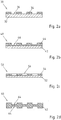
- FIGS. 1a to 1c an embodiment of a method according to the invention is shown.
- Fig. 1a shows a board 2, which has a reduced wall thickness in partial areas 4. The reduction of the wall thickness was achieved in the board 2 by stampings 6 on the upper side 8 of the board 2. As a result, the board 2 on its upper side 8 elevations 10.
- the board 2 consists of a steel or a steel alloy, preferably of a manganese-boron steel, in particular of a steel 22MnB5 type.
- the stampings 6 may have been introduced into the board 2, for example by means of an embossing roll.
- Fig. 1b shows a tool 12 for press hardening with an upper tool 14 and a lower tool 16.
- the inner surface 18 of the upper tool 14 and the inner surface 20 of the lower tool 16 are adapted to the contour of the component to be produced.
- the upper tool 14 and the lower tool 16 are moved apart.
- the board 2 is then positioned between the upper tool 14 and the lower tool 16, and the upper tool 14 and the lower tool 16 then go back together.
- the board 2 is hot-worked at temperatures which are preferably above the austenitizing temperature.
- the elevations 10 are applied directly to the inner surface 18 of the upper tool 14, while the board 2 are spaced in the partial regions 4 with reduced wall thickness by the Vergargisme 6 of the inner surface 18 of the upper tool 14.
- an air gap 24 is formed in each case between the plate 2 and the inner surface 18 of the upper tool 14 in the region of the stampings 6.
- it is quenched in the tool 12. Due to the direct contact of the elevation 10 with the inner surface 18 of the upper tool 14, the cooling of the board 2 in this area is very fast, so that there is a martensite of the material. In the partial regions 4 with reduced wall thickness, the cooling takes place more slowly due to the air gap 24, so that only little or no martensite occurs in these regions.
- the upper tool 14 and the lower tool 16 are moved apart again and removed from the board 2 and press-hardened component 22 removed.
- the finished component 22 is in Fig. 1c displayed.
- inventive Semifinished product 30 consists of a board 32, have been applied to the patches 34.
- the patches 34 are connected to the board 32 preferably cohesively.
- the wall thickness of the semifinished product 30 is locally increased by the patches 34, so that partial areas 36 with a smaller wall thickness relative to the areas with the patches 34 result between the patches.
- the patches 34 are applied directly to the tool, while an air gap is formed in the partial regions 36.
- the advantage of using patches 34 is that the change in wall thickness of the semifinished product 30 can be achieved in a very simple and flexible manner.
- a semifinished product 40 according to the invention is shown, which is designed as a composite sheet. It has a first circuit board 42 and a second circuit board 44, which is arranged above it and is connected to the first circuit board 42, preferably in a materially bonded manner.
- the second board 44 has embossments 46, so that the wall thickness of the semifinished product 40 is reduced in these areas.
- the stampings 46 may be inserted into the second board 44, for example, before the second board 44 is connected to the first board. In this way, it is possible, for example, to produce the second circuit board 44 in advance and emboss and apply it as needed on first boards 42, which should not have press-hardened portions. Furthermore, by using different materials for the first board 42 and the second board 44, it is possible to flexibly influence the material properties of the resulting semi-finished product 40.
- This in Fig. 2c shown semifinished product 50 is also made as a composite sheet of a first board 52 and a second board 54.
- the second board 54 of the semifinished product 50 has no stampings, but continuous recesses 56.
- the recesses 56 may be in the form of bores, for example.
- the recesses 56 may be provided by punching the second board 54.
- a conventional perforated plate made of steel or a steel alloy can be used as the second circuit board 54, since this is particularly cost-effective and thus the wall thickness-reduced areas of the semifinished product 50 can be provided in a simple and favorable manner.
- the semi-finished products or blanks are not limited to provide the portions of reduced wall thickness by one-sided provision of recesses or stampings. This is how the in Fig. 2d Semifinished product 60 shown on a board 62, in which stampings 64 have been introduced from both sides. In this way, the hot-formed semi-finished product 60 has an air gap to the upper or lower tool on both sides in the thickness-reduced subregions. This is particularly advantageous when both the upper and the lower tool are actively cooled during press hardening. As a result, a particularly slow cooling process is possible in these subareas, so that the material has essentially no martensite in this area.
- FIGS. 3a and 3b two embodiments of the press-hardened metal component are shown.
- This in Fig. 3a shown metal component 70 was made of a locally stamped Board made.
- the metal component 70 thus has a first region 72 and a second region 74. Rectangular depressions 76 were introduced into the first region 72 before the press-hardening.
- the second region 74 has no such depressions.
- the metal component 70 was made of a board, for example the one in FIG Fig. 1a shown board 2, first in the in Fig. 3a hot-formed form and then quenched in the tool.
- the metal component 70 in the second region 74 was in direct contact with the tool surfaces over the entire surface, the first region 72 had air gaps on the rectangular stampings 76, so that the component 70 was not press-hardened at these locations.
- the second region 74 of the component 70 is thus completely press-hardened and accordingly has a high hardness, while the first region 72 of the component 70 has a lower hardness due to the non-press-hardened partial regions in the depressions 76 on average.
- Such areas with lower average hardness are preferably arranged according to load.
- the arrangement is particularly advantageous in those places where high elongation at break values are required.
- Metal component 80 shown differs from metal component 70 Fig. 3a in that the metal component 80 is designed as a composite metal sheet.
- the first region 82 and the second region 84 of the metal component 80 were each press-hardened separately and then joined together at the seam 86 by a joining process.
- the stampings 76, 88 of the components 70, 80 are not limited to a rectangular shape, but can also in any other shapes, such as circular, be designed as a polygon or strip-shaped.
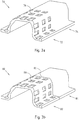
- Fig. 4a a further embodiment of a press-hardened metal component 90, which was produced from a locally stamped board.
- the component 90 has a first region 92 with Vergargungen 94 and a second region 96 without stampings. Accordingly, the component 90 is not press-hardened in the region of the stampings 94, which in this case are strip-shaped, so that the first region 92 has a lower average hardness than the second region 96 Fig. 4b
- the metal component 100 shown differs from the metal component 90 Fig. 4a in that it has been produced from tailored blanks or tailored strips with different sheet thicknesses.
- a tailored blank 102 and two tailored strips 104, 106 with the same thickness and two tailored strips 108, 110 with a smaller thickness were added to a semifinished product and then press-hardened.
- an air gap was arranged between the semifinished product and the tool in the area of the tailored strips 108, 110 with a smaller wall thickness.
- the metal component 100 is not press-hardened in the area of the tailored strips 108, 110 with a smaller thickness.
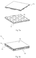
- Fig. 5a and Fig. 5b show a further embodiment of a press-hardened metal component.
- the metal component 111 shown here consists of a lower metal component 112 and an upper metal component 114.
- the lower metal component 112 and the upper metal component 114 are identical in construction and independent of each other in one Press hardening process produced.
- the two metal components 112, 114 each have honeycomb-shaped recesses on one side, in the region of which there was no direct contact with the tool during the press-hardening.
- the metal components 112, 114 are therefore not press-hardened in these areas.
- the metal components 112, 114 with sides having depressions are joined together, preferably welded.
- the resulting composite sheet 111 has on average by the stampings of the metal components 112, 114 lower hardness than a fully press-hardened composite sheet.
- the composite metal sheet 111 advantageously has smooth outer surfaces 118, 120.
- the metal components 112, 114 are first joined together with the recesses having sides, and then press-hardened, optionally also a corresponding shape can be provided. Also in this example, the force gap between the sheets causes an average reduced hardness as a fully press-hardened composite sheet.
- the invention is not limited to the described embodiments, but that in particular all combinations of the embodiments are possible.
- the properties of the press-hardened metal components can be generally improved by the fact that the blanks, semi-finished or finished metal components by one or more typical metallic or non-metallic coating concepts are coated.
- the blanks, semi-finished or finished metal components by one or more typical metallic or non-metallic coating concepts are coated.
- tailored blanks and tailored strips it is basically possible and may be advantageous to use different steel materials.
Description
Die Erfindung betrifft ein Verfahren zur Herstellung eines pressgehärteten Metallbauteils aus Stahl oder einer Stahllegierung, bei welchem eine Platine oder ein Halbzeug in einem Umformwerkzeug pressgehärtet wird. Die Erfindung betrifft auch ein pressgehärtetes Metallbauteil aus Stahl oder einer Stahllegierung, insbesondere für ein Kraftfahrzeug, welches in mindestens einem Teilbereich nicht pressgehärtet ist.The invention relates to a method for producing a press-hardened metal component made of steel or a steel alloy, in which a printed circuit board or a semifinished product is press-hardened in a forming tool. The invention also relates to a press-hardened metal component made of steel or a steel alloy, in particular for a motor vehicle, which is not press-hardened in at least one partial area.
Zur Herstellung von Kraftfahrzeugkarosserien oder Gehäusen sind in der Regel Bauteile hoher Härte erforderlich. Bei Bauteilen aus Stahl oder einer Stahllegierung lassen sich eine sehr hohe Festigkeit und eine sehr hohe Härte durch das Verfahren des Presshärtens erreichen. Bei diesem Verfahren wird eine Platine oder ein Halbzeug in einem Werkzeug bei Temperaturen oberhalb der Austenitisierungstemperatur warmumgeformt und danach in demselben Werkzeug schlagartig abgekühlt. Das während des Warmumformens vorliegende austenitische Gefüge des Bauteils wird durch den schnellen Abkühlvorgang in ein martensitisches Gefüge hoher Festigkeit und Härte umgewandelt. Abhängig von der zu erwartenden Belastung in einer Fahrzeugkarosserie oder in einem Gehäuse ist es bei einigen Bauteilen erforderlich, dass diese keine durchgehende Härte, sondern Bereiche mit einer geringeren Härte oder mit einer erhöhten Bruchdehnung aufweisen. Dies lässt sich insbesondere dadurch erreichen, dass die Bauteile in den Bereichen, in denen sie eine geringere Härte aufweisen sollen, nicht pressgehärtet werden.For the production of motor vehicle bodies or housings components of high hardness are usually required. For components made of steel or a steel alloy, a very high strength and a very high hardness can be achieved by the process of press hardening. In this method, a board or a semi-finished product is hot-worked in a tool at temperatures above the austenitizing temperature and then cooled abruptly in the same tool. The austenitic structure of the component during hot forming is converted into a martensitic structure of high strength and hardness by the rapid cooling process. Depending on the expected load in a vehicle body or in a housing, it is necessary for some components that they have no continuous hardness, but areas with a lower hardness or with an increased elongation at break. This can be achieved in particular by the fact that the components should not be press-hardened in those areas where they should have lower hardness.
Zur Herstellung derartiger Bauteile ist aus der,
Das beschriebene Verfahren hat jedoch den Nachteil, dass die mit den Ausnehmungen versehenen Gesenke aufwendig herzustellen sind. Weiterhin ist es zur Herstellung im Prinzip gleichartiger Bauteile, die lediglich andere Bereiche mit verringerter Härte aufweisen sollen, erforderlich, für jedes Bauteil ein eigenes Gesenk zur Verfügung zu haben. Dadurch werden die Kosten zur Herstellung derartiger Bauteile stark erhöht. Durch die Ausnehmungen im Werkzeug kann es zudem zu Deformationen im Bauteil kommen, so dass eine genaue Formgebung des Bauteils mit diesem Verfahren schwierig und teilweise sogar unmöglich ist.However, the method described has the disadvantage that the provided with the recesses dies are expensive to manufacture. Furthermore, it is for the production in principle of similar components, which should have only other areas with reduced hardness, it is necessary to have a separate die for each component. As a result, the cost of producing such components are greatly increased. The recesses in the tool can also lead to deformations in the component, so that an accurate shaping of the component with this method is difficult and sometimes even impossible.
Aus der
Die
Gemäß
Ausgehend von diesem Stand der Technik liegt der Erfindung die Aufgabe zugrunde, ein einfaches und kostengünstiges Verfahren zur Herstellung eines pressgehärteten Metallbauteils sowie ein pressgehärtetes Metallbauteil aus Stahl oder einer Stahllegierung zur Verfügung zu stellen, bei denen die Nachteile aus dem Stand der Technik vermieden werden.Based on this prior art, the present invention seeks to provide a simple and inexpensive method for producing a press-hardened metal component and a press-hardened metal component made of steel or a steel alloy, in which the disadvantages of the prior art are avoided.
Diese Aufgabe wird mit einem Verfahren mit den Merkmalen gemäß Patentanspruch 1 und mit einem Metallbauteil mit den Merkmalen des Patentanspruches 3 gelöst.This object is achieved by a method having the features according to patent claim 1 and with a metal component having the features of patent claim 3.
Erfindungsgemäß weisen die Platine oder das Halbzeug Teilbereiche mit reduzierter Wanddicke auf, wobei die Teilbereiche mit reduzierter Wanddicke nicht pressgehärtet werden.According to the invention, the printed circuit board or the semi-finished product has partial regions with a reduced wall thickness, the partial regions having a reduced wall thickness not being press-hardened.
Durch die reduzierte Wanddicke liegt die Platine oder das Halbzeug in den entsprechenden Teilbereichen nicht direkt an der Wand des zur Umformung verwendeten Werkzeugs an, so dass sich zwischen diesem Teilbereich der Platine bzw. des Halbzeugs und der Wand des Werkzeugs Luftspalte ausbilden. Beim Abkühlen des Bauteils im Presshärtverfahren ist der Wärmetransport von der Platine bzw. dem Halbzeug zum Werkzeug durch die Luftspalte reduziert, so dass langsamere Abkühlgeschwindigkeiten auftreten. Das Bauteil wird somit in diesen Bereichen nicht pressgehärtet. Dies hat insbesondere zur Folge, dass sich in diesen Teilbereichen nur eine geringe oder sogar gar keine martensitische Gefügestruktur ausbilden kann und die Härte in diesen Bereichen somit geringer und der Bruchdehnungswert größer ist.As a result of the reduced wall thickness, the board or the semifinished product in the corresponding subregions does not lie directly against the wall of the tool used for reshaping, so that air gaps form between this subarea of the board or semifinished product and the wall of the tool. During cooling of the component in the press-hardening process, the heat transfer from the blank or semi-finished product to the tool is reduced through the air gaps, so that slower cooling rates occur. The component is thus not press-hardened in these areas. This has in particular the consequence that only a small or even no martensitic microstructure can form in these subregions and the hardness in these areas is thus lower and the elongation at break value greater.
Der Vorteil dieses Verfahrens liegt darin begründet, dass es auf diese Weise mit einem regulären Presshärtwerkzeug möglich ist, ein Bauteil herzustellen, das Teilbereiche mit einer geringeren Härte bzw. einem höheren Bruchdehnungswert aufweist. Es ist damit insbesondere nicht erforderlich, das Werkzeug in den nicht presszuhärtenden Teilbereichen besonders auszugestalten. Auf diese Weise werden die Kosten bei der Herstellung erheblich reduziert.The advantage of this method lies in the fact that it is possible in this way with a regular press-hardening tool to produce a component having portions with a lower hardness or a higher elongation at break value. It is therefore not necessary in particular to design the tool in the non-press-hardened sub-areas. In this way, the cost of production is significantly reduced.
Erfindungsgemäß werden die Teilbereiche mit reduzierter Wanddicke durch Verprägen der Platine oder des Halbzeugs vor dem Presshärten bereitgestellt. Durch das Verprägen lassen sich die Vertiefungen auf besonders einfache Weise erzeugen. So kann hierzu insbesondere ein Prägestempel oder eine Prägewalze, die besonders bei der Verprägung großer Bereiche vorteilhaft ist, verwendet werden.According to the invention, the subregions are provided with reduced wall thickness by embossing the blank or semifinished product prior to press hardening. By embossing the depressions can be produced in a particularly simple manner. For this purpose, in particular an embossing punch or an embossing roll, which is particularly advantageous in the embossing of large areas, can be used.
In einer weiteren Ausführungsform des Verfahrens wird ein "Tailored Blank" pressgehärtet.In a further embodiment of the method, a "tailored blank" is press-hardened.
"Tailored Blanks" sind einzelne Platinen, die mittels einer Fügetechnik zu einer einzigen Platine zusammengeschweißt werden. Hierdurch können beispielsweise Platinen mit gleichen Werkstoffen, aber unterschiedlichen Blechdicken bzw. verschiedenen Werkstoffen mit gleicher oder unterschiedlicher Blechdicke zu einer Platine verschweißt werden."Tailored blanks" are individual blanks that are welded together using a joining technique to form a single board. As a result, for example, blanks with the same materials, but different sheet thicknesses or different materials with the same or different sheet thickness can be welded to form a board.
Der Einsatz von Tailored Blanks in dem Verfahren ist vorteilhaft, da auf diese Weise Bauteile mit komplexen Formen und variablen Materialeigenschaften hergestellt werden können. Weiterhin lassen sich die Verringerungen der Wanddicken in den Teilbereichen auf sehr einfache und flexible Weise erreichen.The use of tailored blanks in the process is advantageous because in this way components with complex shapes and variable material properties can be produced. Furthermore, the reductions in the wall thicknesses in the subregions can be achieved in a very simple and flexible manner.
Das Tailored Blank weist bevorzugt mindestens eine Platine ohne Verprägung und mindestens eine Platine mit Verprägung auf. Alternativ weist das Tailored Blank mindestens zwei verprägte Platinen unterschiedlicher Dicke auf.The tailored blank preferably has at least one board without embossing and at least one board with embossing. Alternatively, the tailored blank has at least two embossed boards of different thickness.
Bei den sogenannten "Tailored Rolled Blanks" wird über ein flexibles Walzverfahren ein Werkstoff über die Länge unterschiedlich dick gewalzt. Dies erlaubt eine Dickenreduzierung in den Werkstücken mit einem kontinuierlichen Materialübergang, so dass Härtekanten beim Übergang zu den nicht pressgehärteten Teilbereichen des Bauteils vermieden werden. Bevorzugt wird dabei ein Tailored Rolled Blank aus zuvor verprägtem Vormaterial pressgehärtet.In the case of the so-called "tailored rolled blanks", a material is rolled to different thickness over its length using a flexible rolling process. This allows a reduction in thickness in the workpieces with a continuous material transition, so that hardness edges are avoided in the transition to the non-press-hardened portions of the component. Preferably, a tailored rolled blank is press-hardened from previously embossed starting material.
Bei dem erfindungsgemäßen, pressgehärteten Metallbauteil aus Stahl oder einer Stahllegierung, insbesondere für ein Kraftfahrzeug, weist mindestens ein nicht pressgehärteter Teilbereich gegenüber den pressgehärteten Teilbereichen eine reduzierte Wanddicke aufweist. Das Metallbauteil wird vorzugsweise mit einem erfindungsgemäßen Verfahren hergestellt.In the case of the press-hardened metal component according to the invention made of steel or a steel alloy, in particular for a motor vehicle, at least one non-press-hardened partial region has a reduced wall thickness compared with the press-hardened partial regions. The metal component is preferably produced by a method according to the invention.
Durch die reduzierte Wanddicke wird auf einfache Weise erreicht, dass die entsprechenden Teilbereiche nach dem Presshärten des Metallbauteils nicht pressgehärtet sind. Derartige Metallbauteile können vorteilhaft beispielsweise für Kraftfahrzeugkarosserien oder Gehäuse eingesetzt werden, da sie den dort erforderlichen variablen Materialeigenschaften genügen und zudem kostengünstig herzustellen sind.Due to the reduced wall thickness is achieved in a simple manner that the corresponding portions are not press-hardened after the press-hardening of the metal component. Such metal components can be used advantageously, for example, for motor vehicle bodies or housing, since they meet the variable material properties required there and are also inexpensive to manufacture.
Eine flexible Anpassung der Metallbauteile an die Belastungserfordernisse wird gemäß einer weiteren Ausführungsform dadurch erreicht, dass die nicht pressgehärteten Teilbereiche des Metallbauteils belastungsgerecht angeordnet sind. Da hierbei lediglich die Teilbereiche mit einer reduzierten Wanddicke entsprechend angeordnet werden müssen, ohne dass eine Anpassung des zur Herstellung benötigten Werkzeugs erforderlich ist, kann die Herstellung eines derartigen Bauteils einfach und kostengünstig erfolgen. Die nicht pressgehärteten Teilbereiche des Metallbauteils werden dabei bevorzugt in Bereichen angeordnet, in denen das Metallbauteil eine erhöhte Bruchdehnung aufweisen soll.A flexible adaptation of the metal components to the load requirements is achieved according to a further embodiment in that the non-press-hardened portions of the metal component are arranged load. Since in this case only the subregions with a reduced wall thickness have to be arranged correspondingly, without an adaptation of the tool required for the manufacture being required, the production of such a component can be carried out simply and inexpensively. The non-press-hardened portions of the metal component are preferably arranged in areas in which the metal component should have an increased elongation at break.
Eine besonders hohe Härte bzw. Festigkeit des Metallbauteils wird in einer weiteren Ausführungsform dadurch erreicht, dass das Metallbauteil aus einem Mangan-Bor-Stahl, vorzugsweise aus einem Stahl vom Typ 22MnB5 besteht.A particularly high hardness or strength of the metal component is achieved in a further embodiment in that the metal component consists of a manganese-boron steel, preferably of a steel type 22MnB5.
Erfindungsgemäß werden die Teilbereiche des pressgehärteten Metallbauteils mit reduzierter Wanddicke durch Verprägung gebildet. Auf diese Weise sind die Teilbereiche reduzierter Wanddicke besonders einfach herzustellen und flexibel anzuordnen.According to the invention, the subareas of the press-hardened metal component with reduced wall thickness are formed by embossing. In this way, the portions of reduced wall thickness are particularly easy to manufacture and flexible to arrange.
Eine weitere bevorzugte Ausführungsform des pressgehärteten Metallbauteils ist dadurch gegeben, dass die Verprägungen streifenförmig ausgebildet sind. Dies ist zum Beispiel insbesondere dann vorteilhaft, wenn das Metallbauteil Kanten mit geringerer Härte, beispielsweise Sollbiegekanten, aufweisen soll.Another preferred embodiment of the press-hardened metal component is given by the fact that the embossments are formed strip-shaped. This is particularly advantageous, for example, if the metal component is to have edges of lesser hardness, for example predetermined bending edges.
Eine gleichmäßigere Härteverteilung lässt sich in einer weiteren Ausführungsform dadurch erreichen, dass die Verprägungen punkt- oder rechteckförmig ausgebildet sind. Unter einer punktförmigen Verprägung wird dabei beispielsweise eine kreisförmige Verprägung, aber auch allgemein eine Verprägung mit kleinem Seitenverhältnis verstanden.A more even hardness distribution can be achieved in a further embodiment in that the stampings are formed point or rectangular. Under a punctiform embossment is understood, for example, a circular embossing, but also generally a stamp with a small aspect ratio.
In einer weiteren Ausführungsform des pressgehärteten Metallbauteils sind die Verprägungen gleichartig ausgebildet und/oder gleichmäßig in den nicht pressgehärteten Teilbereichen verteilt. Auf diese Weise lassen sich Bereiche mit einer gleichmäßigen mittleren Härte erreichen. Die Ausbildung gleichartiger bzw. gleichmäßig verteilter Verprägungen ist zudem einfacher und kostengünstiger. So kann die Verprägung des Halbzeugs zur Herstellung des Metallbauteils vor dem Presshärten beispielsweise mit Hilfe einer Prägewalze erfolgen.In a further embodiment of the press-hardened metal component, the stampings are of a similar design and / or uniformly distributed in the non-press-hardened partial areas. In this way, areas with a uniform average hardness can be achieved. The training uniform or evenly distributed Stamping is also easier and less expensive. Thus, the embossing of the semifinished product for the production of the metal component can take place before the press hardening, for example with the aid of an embossing roller.
Durch nicht gleichartig ausgebildete bzw. nicht gleichmäßig verteilte Verprägungen lassen sich hingegen sehr flexible mittlere Härteeigenschaften des Metallbauteils erreichen. Auf diese Weise kann beispielsweise ein mittlerer Härtegradient ausgebildet werden.By not identically designed or not uniformly distributed stampings, however, can be achieved very flexible average hardness properties of the metal component. In this way, for example, a medium hardness gradient can be formed.
Ein pressgehärtetes Metallbauteil mit einer gesamten mittleren Härte zwischen einem pressgehärteten und einem nicht pressgehärteten Bauteil lässt sich in einer weiteren bevorzugten Ausführungsform dadurch erreichen, dass das Metallbauteil im Wesentlichen über seine gesamte Oberfläche Verprägungen aufweist.A press-hardened metal component with a total average hardness between a press-hardened and a non-press-hardened component can be achieved in a further preferred embodiment by virtue of the metal component having embossings substantially over its entire surface.
Eine weitere Ausführungsform des pressgehärteten Bauteils ist dadurch gegeben, dass das Metallbauteil aus einem Verbundblech hergestellt ist, welches mindestens zwei Platinen aufweist und eine der Platinen zur Bereitstellung von Teilbereichen verringerter Wanddicke Verprägungen aufweist. Dies ist vorteilhaft, da die Platine mit den Ausnehmungen und/oder Verprägungen separat herstellbar ist. Ferner ist durch die Wahl verschiedener Materialien für die Platinen ein großer Einfluss auf die Materialeigenschaften des Metallbauteils möglich.A further embodiment of the press-hardened component is given by the fact that the metal component is produced from a composite sheet which has at least two sinkers and one of the sinkers has deformations in order to provide partial regions of reduced wall thickness. This is advantageous because the board with the recesses and / or stampings can be produced separately. Furthermore, a large influence on the material properties of the metal component is possible by the choice of different materials for the boards.
Eine besonders flexible und kostengünstige Herstellung ist vor allem bei komplexen pressgehärteten Metallbauteilen dadurch möglich, dass das Metallbauteil aus einem Tailored Blank, einem Tailored Strip oder einem Tailored Rolled Blank hergestellt ist. Bei einem Tailored Blank bzw. einem Tailored Strip können dabei insbesondere Platinen aus verschiedenen Stählen verwendet werden.A particularly flexible and cost-effective production is especially in complex press-hardened metal components possible in that the metal component is made of a tailored blank, a tailored strip or a tailored rolled blank. In the case of a tailored blank or a tailored strip, blanks of different steels in particular can be used.
Weiterhin ist bevorzugt, dass das Metallbauteil aus einem Tailored Blank aus mindestens zwei verprägten Platinen unterschiedlicher Blechdicke hergestellt wurde bzw. dass das Metallbauteil aus einem Tailored Blank oder einem Tailored Strip aus gefügten Platinen unterschiedlicher Blechdicke hergestellt wurde.Furthermore, it is preferred that the metal component was produced from a tailored blank made from at least two embossed blanks of different sheet thickness or that the metal component was produced from a tailored blank or a tailored strip made from joined blanks of different sheet thickness.
Weiterhin ist bevorzugt, dass das Metallbauteil aus einem Tailored Rolled Blank aus zuvor verprägtem Vormaterial hergestellt wurde.Furthermore, it is preferred that the metal component has been produced from a tailored rolled blank of previously embossed starting material.
Weitere Merkmale und Vorteile der Erfindung können der nachfolgenden Beschreibung von Ausführungsbeispielen entnommen werden. Dabei wird Bezug auf die beigefügte Zeichnung genommen.Further features and advantages of the invention can be taken from the following description of exemplary embodiments. Reference is made to the attached drawing.
In der Zeichnung zeigen
- Fig. 1a-c
- ein Ausführungsbeispiel eines erfindungsgemäßen Verfahrens,
- Fig. 2a-d
- vier Ausführungsbeispiele eines Halbzeugs mit Teilbereichen reduzierter Wanddicke zur Herstellung von Metallbauteilen,
- Fig. 3a-b
- zwei Ausführungsbeispiele eines erfindungsgemäßen Metallbauteils,
- Fig. 4a-b
- zwei weitere Ausführungsbeispiele eines erfindungsgemäßen Metallbauteils und
- Fig. 5a-b
- ein weiteres Ausführungsbeispiel eines erfindungsgemäßen Metallbauteils.
- Fig. 1a-c
- an embodiment of a method according to the invention,
- Fig. 2a-d
- Four embodiments of a semifinished product with partial regions of reduced wall thickness for the production of metal components,
- Fig. 3a-b
- two embodiments of a metal component according to the invention,
- Fig. 4a-b
- two further embodiments of a metal component according to the invention and
- Fig. 5a-b
- a further embodiment of a metal component according to the invention.
In den
In den
In
Das in
Die Halbzeuge bzw. Platinen sind nicht darauf beschränkt, die Teilbereiche reduzierter Wanddicke durch einseitiges Vorsehen von Ausnehmungen oder Verprägungen bereitzustellen. So weist das in
In den
Das in
Die Verprägungen 76, 88 der Bauteile 70, 80 sind nicht auf eine rechteckige Form beschränkt, sondern können auch in beliebigen anderen Formen, beispielsweise kreisförmig, als Vieleck oder streifenförmig ausgestaltet sein.The
So zeigt
Denkbar wäre auch eine nicht dargestellte Anwendung, bei welcher die Metallbauteile 112, 114 zunächst mit den Vertiefungen aufweisenden Seiten zueinander, miteinander gefügt und anschließend pressgehärtet werden, wobei optional auch eine entsprechenden Formgebung vorgesehen sein kann. Auch in diesem Beispiel bewirkt der Kraftspalt zwischen den Blechen eine im Mittel verringerte Härte als ein vollständig pressgehärtetes Verbundblech.Also conceivable would be an application, not shown, in which the
Es ergibt sich für den Fachmann, dass die Erfindung nicht auf die beschriebenen Ausführungsbeispiele beschränkt ist, sondern dass insbesondere auch alle Kombinationen der Ausführungsbeispiele möglich sind. Die Eigenschaften der pressgehärteten Metallbauteile lassen sich allgemein dadurch verbessern, dass die Platinen, Halbzeuge oder fertigen Metallbauteile durch ein oder mehrere typische metallische oder nichtmetallische Beschichtungskonzepte beschichtet werden. Bei allen Verbundblechen, Tailored Blanks und Tailored Strips ist es grundsätzlich möglich und unter Umständen vorteilhaft, verschiedene Stahlwerkstoffe zu verwenden.It will be apparent to those skilled in the art that the invention is not limited to the described embodiments, but that in particular all combinations of the embodiments are possible. The properties of the press-hardened metal components can be generally improved by the fact that the blanks, semi-finished or finished metal components by one or more typical metallic or non-metallic coating concepts are coated. In all composite sheets, tailored blanks and tailored strips, it is basically possible and may be advantageous to use different steel materials.
Claims (10)
- A method of producing a press-hardened metal component of steel or a steel alloy,- in which a blank (2) or a semi-finished product (30, 40, 50, 60) is press hardened in a forming tool (12),characterised in that- the blank (2) or the semi-finished product (30, 40, 50, 60) comprises partial areas (4, 36) with a reduced wall thickness,- the partial areas (4, 36) with a reduced wall thickness are produced through embossing the blank (2) or the semi-finished product (30, 40, 50, 60) before press hardening and,- the partial areas (4, 36) with a reduced wall thickness are not press hardened.
- The method according to claim 1,
characterised in that
a composite sheet (40, 50) is press hardened, wherein the composite sheet (40, 50) comprises at least two blanks (42, 44, 52, 54) and one of the blanks (44, 54) has stampings (46) for providing partial areas with a reduced wall thickness. - A press-hardened metal component of steel or a steel alloy, more particularly for a motor vehicle, manufactured with a method according to one of claims 1 or 2,- which in at least one partial area (4, 36) is not press-hardened,characterised in that- at least one non-press-hardened partial area (4, 36) has a reduced wall thickness compared with the press-hardened partial area, and- the partial areas (4, 36) with a reduced wall thickness are formed by stampings (46, 64, 76, 94).
- The press-hardened metal component according to claim 3,
characterised in that
the non-press-hardened partial areas (4, 36) of the metal component (22, 70, 80, 90, 100, 111) are arranged so as to be adapted to loading. - The press-hardened metal component according to claim 3 or 4, characterised in that
the metal component (22, 70, 80, 90, 100, 111) is made of manganese-boron steel, preferably a steel of type 22MnB5. - The press-hardened metal component according to any one of claims 3 to 5, characterised in that
the stampings (94) are configured in the form of strips. - The press-hardened metal component according to any one of claims 3 to 6, characterised in that
the stampings (46, 64, 76) are punctiform or rectangular. - The press-hardened metal component according to any one of claims 3 to 7, characterised in that
the stampings (46, 64, 76, 94) are configured similarly and/or are uniformly distributed in the non-press-hardened partial areas. - The press-hardened metal component according to any one of claims 3 to 8, characterised in that
the metal component (22, 70, 80, 90, 100, 111) exhibits stampings (46, 64, 76, 94) substantially over its entire surface. - The press-hardened metal component according to any one of claims 3 to 9, characterised in that
the metal component (22, 70, 80, 90, 100, 111) is produced from a composite sheet (40, 50) which comprises at least two blanks (42, 44, 52, 54) and one of the blanks (44, 54) has stampings (46) for the provision of partial areas with a reduced wall thickness.
Priority Applications (1)
| Application Number | Priority Date | Filing Date | Title |
|---|---|---|---|
| PL10701860T PL2398606T3 (en) | 2009-02-19 | 2010-01-27 | Method for producing a press-quenched metal component |
Applications Claiming Priority (2)
| Application Number | Priority Date | Filing Date | Title |
|---|---|---|---|
| DE102009003508A DE102009003508B4 (en) | 2009-02-19 | 2009-02-19 | Process for producing a press-hardened metal component |
| PCT/EP2010/050931 WO2010094538A1 (en) | 2009-02-19 | 2010-01-27 | Method for producing a press-quenched metal component |
Publications (2)
| Publication Number | Publication Date |
|---|---|
| EP2398606A1 EP2398606A1 (en) | 2011-12-28 |
| EP2398606B1 true EP2398606B1 (en) | 2017-08-09 |
Family
ID=41815606
Family Applications (1)
| Application Number | Title | Priority Date | Filing Date |
|---|---|---|---|
| EP10701860.8A Active EP2398606B1 (en) | 2009-02-19 | 2010-01-27 | Method for producing a press-quenched metal component |
Country Status (10)
| Country | Link |
|---|---|
| US (1) | US20120040205A1 (en) |
| EP (1) | EP2398606B1 (en) |
| JP (1) | JP2012517901A (en) |
| KR (1) | KR20110122679A (en) |
| CN (1) | CN102317001B (en) |
| CA (1) | CA2752855C (en) |
| DE (1) | DE102009003508B4 (en) |
| ES (1) | ES2646314T3 (en) |
| PL (1) | PL2398606T3 (en) |
| WO (1) | WO2010094538A1 (en) |
Cited By (1)
| Publication number | Priority date | Publication date | Assignee | Title |
|---|---|---|---|---|
| DE102022114057A1 (en) | 2022-06-03 | 2023-12-14 | Bayerische Motoren Werke Aktiengesellschaft | Press-hardened sheet metal part with different sheet thicknesses and strengths |
Families Citing this family (24)
| Publication number | Priority date | Publication date | Assignee | Title |
|---|---|---|---|---|
| DE102011007937B4 (en) * | 2011-01-03 | 2015-09-10 | Benteler Automobiltechnik Gmbh | Method for producing a structural component of a motor vehicle body |
| DE102011009891A1 (en) * | 2011-01-31 | 2012-08-02 | Benteler Automobiltechnik Gmbh | Method for manufacturing metal sheet part, involves providing sheet metal board with thick region and thin region, where thin region is bent such that seam runs along thickness transition at flat surface |
| DE102011051728A1 (en) * | 2011-07-11 | 2013-01-17 | Thyssenkrupp Lasertechnik Gmbh | Method and device for producing tailor-made sheet-metal strips |
| DE102011052291B4 (en) * | 2011-07-29 | 2016-03-10 | Benteler Automobiltechnik Gmbh | Motor vehicle component and method for producing a motor vehicle component |
| DE102011116715A1 (en) * | 2011-10-22 | 2013-04-25 | Volkswagen Aktiengesellschaft | Apparatus and method for thermoforming / press hardening and cutting a sheet metal material in a tool with automated removal of the sheet metal waste |
| JP2013233548A (en) * | 2012-05-02 | 2013-11-21 | Unipres Corp | Hot press molding device |
| DE102012015431A1 (en) * | 2012-08-03 | 2014-02-06 | Voestalpine Stahl Gmbh | Component with sandwich structure and method for its production |
| DE102012110138B3 (en) * | 2012-10-24 | 2014-02-27 | Manuela Braun | Apparatus and method for press hardening of sheet metal blanks and / or sheet metal parts made of steel with different material thickness |
| CN104232871B (en) * | 2013-06-06 | 2017-06-16 | 天龙科技炉业(无锡)有限公司 | train wheel integral quenching technique |
| DE102013214250A1 (en) | 2013-07-22 | 2015-01-22 | Bayerische Motoren Werke Aktiengesellschaft | Press-hardened sheet metal component with perforation and method for its production |
| US20150314363A1 (en) * | 2014-04-30 | 2015-11-05 | GM Global Technology Operations LLC | Method of forming a vehicle body structure from a pre-welded blank assembly |
| DE102015203644A1 (en) * | 2015-03-02 | 2016-09-08 | Bayerische Motoren Werke Aktiengesellschaft | Press-hardened sheet metal part with different sheet thicknesses and strengths |
| DE102015220347B4 (en) * | 2015-10-20 | 2018-06-21 | Thyssenkrupp Ag | Method for producing a component for a vehicle |
| DE102016201036A1 (en) | 2016-01-26 | 2017-07-27 | Zf Friedrichshafen Ag | Method for producing a component and component produced by this method |
| JP6724452B2 (en) * | 2016-03-18 | 2020-07-15 | 日本製鉄株式会社 | Quenched steel pipe member and method for manufacturing quenched steel pipe member |
| CN109153060B (en) * | 2016-05-18 | 2021-06-25 | 日本制铁株式会社 | Method and production line for manufacturing press-molded article |
| TWI622491B (en) * | 2016-12-16 | 2018-05-01 | 財團法人金屬工業研究發展中心 | Hot stamping forming low heat transfer heating mold and hot stamping part forming method |
| DE102016124931A1 (en) * | 2016-12-20 | 2018-06-21 | Bayerische Motoren Werke Aktiengesellschaft | Method for producing a one-piece reinforcement element for a side frame of a vehicle, reinforcement element for a side frame of a vehicle and vehicle |
| WO2019090109A1 (en) | 2017-11-02 | 2019-05-09 | Ak Steel Properties, Inc. | Press hardened steel with tailored properties |
| DE102017127158A1 (en) * | 2017-11-17 | 2019-05-23 | HoDforming GmbH | Method for forming a sheet metal blank, z. As a board or a hollow body blank as a workpiece in a forming tool |
| JP7155986B2 (en) | 2018-12-13 | 2022-10-19 | トヨタ自動車株式会社 | Steel plate member and its manufacturing method |
| CN113423518A (en) * | 2019-02-13 | 2021-09-21 | 麦格纳国际公司 | Method and system for using air gaps in hot stamping tools to create custom temper properties |
| CN109909379B (en) * | 2019-03-29 | 2020-05-12 | 重庆大学 | Insert block structure of hot stamping forming die and processing method thereof |
| CN112207219B (en) * | 2019-07-12 | 2023-09-22 | 余姚市佳福车业有限公司 | Production and manufacturing method for hot forging inner hole of metal piece |
Citations (4)
| Publication number | Priority date | Publication date | Assignee | Title |
|---|---|---|---|---|
| WO2006038868A1 (en) * | 2004-10-04 | 2006-04-13 | Gestamp Hardtech Ab | A method of hot stamping and hardening a metal sheet |
| DE102005025026B3 (en) * | 2005-05-30 | 2006-10-19 | Thyssenkrupp Steel Ag | Production of metal components with adjacent zones of different characteristics comprises press-molding sheet metal using ram and female mold, surfaces of ram which contact sheet being heated and time of contact being controlled |
| WO2008024042A1 (en) * | 2006-08-25 | 2008-02-28 | Gestamp Hardtech Ab | A method of hot-shaping and hardening an object from a metal sheet, and a b-pillar for a vehicle |
| WO2010133526A1 (en) * | 2009-05-18 | 2010-11-25 | Thyssenkrupp Steel Europe Ag | Method for producing a metal component from a hot-stamped raw material |
Family Cites Families (16)
| Publication number | Priority date | Publication date | Assignee | Title |
|---|---|---|---|---|
| DE19742818A1 (en) * | 1997-09-27 | 1999-04-01 | Volkswagen Ag | Circuit board for a structural component, structural component and method for producing a structural component for motor vehicles |
| DE19743093C1 (en) * | 1997-09-30 | 1998-12-17 | Thyssenkrupp Stahl Ag | Production of a metal strip with regions of different thickness over its width |
| JP4497736B2 (en) * | 2001-03-02 | 2010-07-07 | 本田技研工業株式会社 | Blank material for forming double-layer products |
| JP4316842B2 (en) * | 2002-07-26 | 2009-08-19 | アイシン高丘株式会社 | Method for manufacturing tailored blank press molded products |
| JP2004154853A (en) * | 2002-11-08 | 2004-06-03 | Futaba Industrial Co Ltd | Production method for plastic workpiece |
| DE10333165A1 (en) * | 2003-07-22 | 2005-02-24 | Daimlerchrysler Ag | Production of press-quenched components, especially chassis parts, made from a semi-finished product made from sheet steel comprises molding a component blank, cutting, heating, press-quenching, and coating with a corrosion-protection layer |
| JP3863874B2 (en) * | 2003-10-02 | 2006-12-27 | 新日本製鐵株式会社 | Hot press forming apparatus and hot press forming method for metal plate material |
| DE102004053917B3 (en) * | 2004-11-05 | 2006-04-13 | Benteler Automobiltechnik Gmbh | Sidewall of a motor vehicle |
| DE102007063629B4 (en) * | 2007-08-14 | 2016-07-07 | Benteler Automobiltechnik Gmbh | Method for producing a bumper arrangement of a motor vehicle |
| EP2025771A1 (en) * | 2007-08-15 | 2009-02-18 | Corus Staal BV | Method for producing a coated steel strip for producing taylored blanks suitable for thermomechanical shaping, strip thus produced, and use of such a coated strip |
| DE102007050907A1 (en) * | 2007-10-23 | 2009-04-30 | Benteler Automobiltechnik Gmbh | Process for producing a hardened sheet metal profile |
| DE102008018656B9 (en) * | 2008-04-11 | 2009-07-09 | Thyssenkrupp Steel Ag | Process for producing high-volume half-shells |
| EP2313217B1 (en) * | 2008-07-10 | 2015-06-03 | Shiloh Industries, Inc. | Metal forming process and welded coil assembly |
| DE102008053878B4 (en) * | 2008-10-30 | 2011-04-21 | Benteler Automobiltechnik Gmbh | Thermoforming component and method for producing a thermoformed component |
| SE533825C2 (en) * | 2009-06-15 | 2011-01-25 | Gestamp Hardtech Ab | Ways to form and harden a steel sheet material |
| DE102010004081C5 (en) * | 2010-01-06 | 2016-11-03 | Benteler Automobiltechnik Gmbh | Method for thermoforming and curing a circuit board |
-
2009
- 2009-02-19 DE DE102009003508A patent/DE102009003508B4/en not_active Expired - Fee Related
-
2010
- 2010-01-27 EP EP10701860.8A patent/EP2398606B1/en active Active
- 2010-01-27 CA CA2752855A patent/CA2752855C/en not_active Expired - Fee Related
- 2010-01-27 JP JP2011550500A patent/JP2012517901A/en active Pending
- 2010-01-27 WO PCT/EP2010/050931 patent/WO2010094538A1/en active Application Filing
- 2010-01-27 CN CN201080008202.0A patent/CN102317001B/en not_active Expired - Fee Related
- 2010-01-27 US US13/202,385 patent/US20120040205A1/en not_active Abandoned
- 2010-01-27 KR KR1020117019234A patent/KR20110122679A/en not_active Application Discontinuation
- 2010-01-27 PL PL10701860T patent/PL2398606T3/en unknown
- 2010-01-27 ES ES10701860.8T patent/ES2646314T3/en active Active
Patent Citations (4)
| Publication number | Priority date | Publication date | Assignee | Title |
|---|---|---|---|---|
| WO2006038868A1 (en) * | 2004-10-04 | 2006-04-13 | Gestamp Hardtech Ab | A method of hot stamping and hardening a metal sheet |
| DE102005025026B3 (en) * | 2005-05-30 | 2006-10-19 | Thyssenkrupp Steel Ag | Production of metal components with adjacent zones of different characteristics comprises press-molding sheet metal using ram and female mold, surfaces of ram which contact sheet being heated and time of contact being controlled |
| WO2008024042A1 (en) * | 2006-08-25 | 2008-02-28 | Gestamp Hardtech Ab | A method of hot-shaping and hardening an object from a metal sheet, and a b-pillar for a vehicle |
| WO2010133526A1 (en) * | 2009-05-18 | 2010-11-25 | Thyssenkrupp Steel Europe Ag | Method for producing a metal component from a hot-stamped raw material |
Cited By (1)
| Publication number | Priority date | Publication date | Assignee | Title |
|---|---|---|---|---|
| DE102022114057A1 (en) | 2022-06-03 | 2023-12-14 | Bayerische Motoren Werke Aktiengesellschaft | Press-hardened sheet metal part with different sheet thicknesses and strengths |
Also Published As
| Publication number | Publication date |
|---|---|
| CN102317001B (en) | 2016-02-24 |
| ES2646314T3 (en) | 2017-12-13 |
| EP2398606A1 (en) | 2011-12-28 |
| JP2012517901A (en) | 2012-08-09 |
| DE102009003508B4 (en) | 2013-01-24 |
| US20120040205A1 (en) | 2012-02-16 |
| CA2752855A1 (en) | 2010-08-26 |
| DE102009003508A1 (en) | 2010-09-02 |
| KR20110122679A (en) | 2011-11-10 |
| PL2398606T3 (en) | 2018-01-31 |
| CN102317001A (en) | 2012-01-11 |
| CA2752855C (en) | 2016-10-18 |
| WO2010094538A1 (en) | 2010-08-26 |
Similar Documents
| Publication | Publication Date | Title |
|---|---|---|
| EP2398606B1 (en) | Method for producing a press-quenched metal component | |
| DE102009025821B4 (en) | Method for producing a metal component | |
| EP2155917B1 (en) | Process for producing a locally hardened profile component | |
| DE102008044523B4 (en) | Warmumformprofile | |
| EP0946311B1 (en) | Method for the production of a sheet metal part by forming | |
| EP3160667B1 (en) | Method and forming tool for heat-forming, and corresponding work piece | |
| DE102013114245B3 (en) | Method and device for producing hot-formed wheeled dishes | |
| DE102008020473A1 (en) | Method of producing thickness-varying sheet metal blanks | |
| EP3138708B1 (en) | Stabilizer bar and process of producing the same | |
| DE102014112755B4 (en) | Method for forming a workpiece, in particular a blank, from sheet steel | |
| WO2005075279A1 (en) | Component with a joining region, method and tool for the production thereof | |
| DE102005041741B4 (en) | Method for producing a press-hardened component | |
| DE102015203644A1 (en) | Press-hardened sheet metal part with different sheet thicknesses and strengths | |
| EP2094415B1 (en) | Steering rack | |
| DE102011054866A1 (en) | Preparing hot-formed and press-hardened motor vehicle body component, comprises processing metal sheet circuit board from curable sheet steel in hot-forming and press-hardening tool, and forming area in circuit board as embossing region | |
| EP3177416A1 (en) | Method for producing hot-formed components | |
| DE102014111501B4 (en) | Hot-forming device and method for producing press-hardened molded parts from sheet steel | |
| DE102009053534B4 (en) | Device and method for forming and / or tempering sheet metal components and sheet metal part produced therewith | |
| DE102006062242A1 (en) | molding | |
| WO2019048025A1 (en) | Method for producing a component and tool therefor | |
| EP2586881B1 (en) | Method for producing a moulded part from high-strength steel | |
| EP2314397B1 (en) | Method for producing a workpiece from sheet metal | |
| DE102008016224B4 (en) | Profile part for motor vehicle body with variable profile width | |
| WO2015197485A1 (en) | Method for producing a profiled rail | |
| EP2878460B1 (en) | Carrier assembly for a trailer coupling made from a steel sheet and method for its production |
Legal Events
| Date | Code | Title | Description |
|---|---|---|---|
| PUAI | Public reference made under article 153(3) epc to a published international application that has entered the european phase |
Free format text: ORIGINAL CODE: 0009012 |
|
| 17P | Request for examination filed |
Effective date: 20110728 |
|
| AK | Designated contracting states |
Kind code of ref document: A1 Designated state(s): AT BE BG CH CY CZ DE DK EE ES FI FR GB GR HR HU IE IS IT LI LT LU LV MC MK MT NL NO PL PT RO SE SI SK SM TR |
|
| DAX | Request for extension of the european patent (deleted) | ||
| 17Q | First examination report despatched |
Effective date: 20141212 |
|
| GRAP | Despatch of communication of intention to grant a patent |
Free format text: ORIGINAL CODE: EPIDOSNIGR1 |
|
| INTG | Intention to grant announced |
Effective date: 20170309 |
|
| GRAS | Grant fee paid |
Free format text: ORIGINAL CODE: EPIDOSNIGR3 |
|
| GRAA | (expected) grant |
Free format text: ORIGINAL CODE: 0009210 |
|
| AK | Designated contracting states |
Kind code of ref document: B1 Designated state(s): AT BE BG CH CY CZ DE DK EE ES FI FR GB GR HR HU IE IS IT LI LT LU LV MC MK MT NL NO PL PT RO SE SI SK SM TR |
|
| REG | Reference to a national code |
Ref country code: GB Ref legal event code: FG4D Free format text: NOT ENGLISH |
|
| RIN1 | Information on inventor provided before grant (corrected) |
Inventor name: SIKORA, SASCHA Inventor name: ULRICHS, ANDREAS Inventor name: PATBERG, LOTHAR Inventor name: LENZE, FRANZ-JOSEF |
|
| REG | Reference to a national code |
Ref country code: AT Ref legal event code: REF Ref document number: 916261 Country of ref document: AT Kind code of ref document: T Effective date: 20170815 Ref country code: CH Ref legal event code: EP |
|
| RIN2 | Information on inventor provided after grant (corrected) |
Inventor name: SIKORA, SASCHA Inventor name: ULRICHS, ANDREAS Inventor name: LENZE, FRANZ-JOSEF Inventor name: PATBERG, LOTHAR |
|
| REG | Reference to a national code |
Ref country code: IE Ref legal event code: FG4D Free format text: LANGUAGE OF EP DOCUMENT: GERMAN |
|
| REG | Reference to a national code |
Ref country code: DE Ref legal event code: R096 Ref document number: 502010013968 Country of ref document: DE |
|
| REG | Reference to a national code |
Ref country code: SE Ref legal event code: TRGR |
|
| REG | Reference to a national code |
Ref country code: NL Ref legal event code: MP Effective date: 20170809 Ref country code: ES Ref legal event code: FG2A Ref document number: 2646314 Country of ref document: ES Kind code of ref document: T3 Effective date: 20171213 |
|
| REG | Reference to a national code |
Ref country code: LT Ref legal event code: MG4D |
|
| REG | Reference to a national code |
Ref country code: FR Ref legal event code: PLFP Year of fee payment: 9 |
|
| PG25 | Lapsed in a contracting state [announced via postgrant information from national office to epo] |
Ref country code: FI Free format text: LAPSE BECAUSE OF FAILURE TO SUBMIT A TRANSLATION OF THE DESCRIPTION OR TO PAY THE FEE WITHIN THE PRESCRIBED TIME-LIMIT Effective date: 20170809 Ref country code: NL Free format text: LAPSE BECAUSE OF FAILURE TO SUBMIT A TRANSLATION OF THE DESCRIPTION OR TO PAY THE FEE WITHIN THE PRESCRIBED TIME-LIMIT Effective date: 20170809 Ref country code: LT Free format text: LAPSE BECAUSE OF FAILURE TO SUBMIT A TRANSLATION OF THE DESCRIPTION OR TO PAY THE FEE WITHIN THE PRESCRIBED TIME-LIMIT Effective date: 20170809 Ref country code: HR Free format text: LAPSE BECAUSE OF FAILURE TO SUBMIT A TRANSLATION OF THE DESCRIPTION OR TO PAY THE FEE WITHIN THE PRESCRIBED TIME-LIMIT Effective date: 20170809 Ref country code: NO Free format text: LAPSE BECAUSE OF FAILURE TO SUBMIT A TRANSLATION OF THE DESCRIPTION OR TO PAY THE FEE WITHIN THE PRESCRIBED TIME-LIMIT Effective date: 20171109 |
|
| PG25 | Lapsed in a contracting state [announced via postgrant information from national office to epo] |
Ref country code: GR Free format text: LAPSE BECAUSE OF FAILURE TO SUBMIT A TRANSLATION OF THE DESCRIPTION OR TO PAY THE FEE WITHIN THE PRESCRIBED TIME-LIMIT Effective date: 20171110 Ref country code: LV Free format text: LAPSE BECAUSE OF FAILURE TO SUBMIT A TRANSLATION OF THE DESCRIPTION OR TO PAY THE FEE WITHIN THE PRESCRIBED TIME-LIMIT Effective date: 20170809 Ref country code: IS Free format text: LAPSE BECAUSE OF FAILURE TO SUBMIT A TRANSLATION OF THE DESCRIPTION OR TO PAY THE FEE WITHIN THE PRESCRIBED TIME-LIMIT Effective date: 20171209 Ref country code: BG Free format text: LAPSE BECAUSE OF FAILURE TO SUBMIT A TRANSLATION OF THE DESCRIPTION OR TO PAY THE FEE WITHIN THE PRESCRIBED TIME-LIMIT Effective date: 20171109 |
|
| PG25 | Lapsed in a contracting state [announced via postgrant information from national office to epo] |
Ref country code: DK Free format text: LAPSE BECAUSE OF FAILURE TO SUBMIT A TRANSLATION OF THE DESCRIPTION OR TO PAY THE FEE WITHIN THE PRESCRIBED TIME-LIMIT Effective date: 20170809 Ref country code: RO Free format text: LAPSE BECAUSE OF FAILURE TO SUBMIT A TRANSLATION OF THE DESCRIPTION OR TO PAY THE FEE WITHIN THE PRESCRIBED TIME-LIMIT Effective date: 20170809 |
|
| REG | Reference to a national code |
Ref country code: SK Ref legal event code: T3 Ref document number: E 26382 Country of ref document: SK |
|
| REG | Reference to a national code |
Ref country code: DE Ref legal event code: R097 Ref document number: 502010013968 Country of ref document: DE |
|
| PG25 | Lapsed in a contracting state [announced via postgrant information from national office to epo] |
Ref country code: EE Free format text: LAPSE BECAUSE OF FAILURE TO SUBMIT A TRANSLATION OF THE DESCRIPTION OR TO PAY THE FEE WITHIN THE PRESCRIBED TIME-LIMIT Effective date: 20170809 Ref country code: SM Free format text: LAPSE BECAUSE OF FAILURE TO SUBMIT A TRANSLATION OF THE DESCRIPTION OR TO PAY THE FEE WITHIN THE PRESCRIBED TIME-LIMIT Effective date: 20170809 |
|
| PLBE | No opposition filed within time limit |
Free format text: ORIGINAL CODE: 0009261 |
|
| STAA | Information on the status of an ep patent application or granted ep patent |
Free format text: STATUS: NO OPPOSITION FILED WITHIN TIME LIMIT |
|
| 26N | No opposition filed |
Effective date: 20180511 |
|
| PG25 | Lapsed in a contracting state [announced via postgrant information from national office to epo] |
Ref country code: SI Free format text: LAPSE BECAUSE OF FAILURE TO SUBMIT A TRANSLATION OF THE DESCRIPTION OR TO PAY THE FEE WITHIN THE PRESCRIBED TIME-LIMIT Effective date: 20170809 |
|
| REG | Reference to a national code |
Ref country code: CH Ref legal event code: PL |
|
| PG25 | Lapsed in a contracting state [announced via postgrant information from national office to epo] |
Ref country code: MT Free format text: LAPSE BECAUSE OF FAILURE TO SUBMIT A TRANSLATION OF THE DESCRIPTION OR TO PAY THE FEE WITHIN THE PRESCRIBED TIME-LIMIT Effective date: 20170809 |
|
| PG25 | Lapsed in a contracting state [announced via postgrant information from national office to epo] |
Ref country code: LU Free format text: LAPSE BECAUSE OF NON-PAYMENT OF DUE FEES Effective date: 20180127 |
|
| REG | Reference to a national code |
Ref country code: IE Ref legal event code: MM4A |
|
| REG | Reference to a national code |
Ref country code: BE Ref legal event code: MM Effective date: 20180131 |
|
| PG25 | Lapsed in a contracting state [announced via postgrant information from national office to epo] |
Ref country code: CH Free format text: LAPSE BECAUSE OF NON-PAYMENT OF DUE FEES Effective date: 20180131 Ref country code: LI Free format text: LAPSE BECAUSE OF NON-PAYMENT OF DUE FEES Effective date: 20180131 Ref country code: BE Free format text: LAPSE BECAUSE OF NON-PAYMENT OF DUE FEES Effective date: 20180131 |
|
| PG25 | Lapsed in a contracting state [announced via postgrant information from national office to epo] |
Ref country code: IE Free format text: LAPSE BECAUSE OF NON-PAYMENT OF DUE FEES Effective date: 20180127 |
|
| PG25 | Lapsed in a contracting state [announced via postgrant information from national office to epo] |
Ref country code: MC Free format text: LAPSE BECAUSE OF FAILURE TO SUBMIT A TRANSLATION OF THE DESCRIPTION OR TO PAY THE FEE WITHIN THE PRESCRIBED TIME-LIMIT Effective date: 20170809 |
|
| PGFP | Annual fee paid to national office [announced via postgrant information from national office to epo] |
Ref country code: PL Payment date: 20191227 Year of fee payment: 11 |
|
| PGFP | Annual fee paid to national office [announced via postgrant information from national office to epo] |
Ref country code: AT Payment date: 20200122 Year of fee payment: 11 Ref country code: DE Payment date: 20200121 Year of fee payment: 11 Ref country code: GB Payment date: 20200124 Year of fee payment: 11 Ref country code: ES Payment date: 20200221 Year of fee payment: 11 Ref country code: IT Payment date: 20200131 Year of fee payment: 11 Ref country code: SE Payment date: 20200121 Year of fee payment: 11 |
|
| PG25 | Lapsed in a contracting state [announced via postgrant information from national office to epo] |
Ref country code: HU Free format text: LAPSE BECAUSE OF FAILURE TO SUBMIT A TRANSLATION OF THE DESCRIPTION OR TO PAY THE FEE WITHIN THE PRESCRIBED TIME-LIMIT; INVALID AB INITIO Effective date: 20100127 Ref country code: PT Free format text: LAPSE BECAUSE OF FAILURE TO SUBMIT A TRANSLATION OF THE DESCRIPTION OR TO PAY THE FEE WITHIN THE PRESCRIBED TIME-LIMIT Effective date: 20170809 |
|
| PGFP | Annual fee paid to national office [announced via postgrant information from national office to epo] |
Ref country code: CZ Payment date: 20200123 Year of fee payment: 11 Ref country code: SK Payment date: 20200123 Year of fee payment: 11 |
|
| PG25 | Lapsed in a contracting state [announced via postgrant information from national office to epo] |
Ref country code: MK Free format text: LAPSE BECAUSE OF NON-PAYMENT OF DUE FEES Effective date: 20170809 Ref country code: CY Free format text: LAPSE BECAUSE OF FAILURE TO SUBMIT A TRANSLATION OF THE DESCRIPTION OR TO PAY THE FEE WITHIN THE PRESCRIBED TIME-LIMIT Effective date: 20170809 |
|
| PGFP | Annual fee paid to national office [announced via postgrant information from national office to epo] |
Ref country code: TR Payment date: 20200124 Year of fee payment: 11 Ref country code: FR Payment date: 20200121 Year of fee payment: 11 |
|
| REG | Reference to a national code |
Ref country code: DE Ref legal event code: R119 Ref document number: 502010013968 Country of ref document: DE |
|
| REG | Reference to a national code |
Ref country code: SE Ref legal event code: EUG |
|
| REG | Reference to a national code |
Ref country code: AT Ref legal event code: MM01 Ref document number: 916261 Country of ref document: AT Kind code of ref document: T Effective date: 20210127 |
|
| GBPC | Gb: european patent ceased through non-payment of renewal fee |
Effective date: 20210127 |
|
| REG | Reference to a national code |
Ref country code: SK Ref legal event code: MM4A Ref document number: E 26382 Country of ref document: SK Effective date: 20210127 |
|
| PG25 | Lapsed in a contracting state [announced via postgrant information from national office to epo] |
Ref country code: CZ Free format text: LAPSE BECAUSE OF NON-PAYMENT OF DUE FEES Effective date: 20210127 Ref country code: FR Free format text: LAPSE BECAUSE OF NON-PAYMENT OF DUE FEES Effective date: 20210131 Ref country code: AT Free format text: LAPSE BECAUSE OF NON-PAYMENT OF DUE FEES Effective date: 20210127 |
|
| PG25 | Lapsed in a contracting state [announced via postgrant information from national office to epo] |
Ref country code: SE Free format text: LAPSE BECAUSE OF NON-PAYMENT OF DUE FEES Effective date: 20210128 Ref country code: SK Free format text: LAPSE BECAUSE OF NON-PAYMENT OF DUE FEES Effective date: 20210127 Ref country code: GB Free format text: LAPSE BECAUSE OF NON-PAYMENT OF DUE FEES Effective date: 20210127 Ref country code: DE Free format text: LAPSE BECAUSE OF NON-PAYMENT OF DUE FEES Effective date: 20210803 |
|
| PG25 | Lapsed in a contracting state [announced via postgrant information from national office to epo] |
Ref country code: IT Free format text: LAPSE BECAUSE OF NON-PAYMENT OF DUE FEES Effective date: 20210127 |
|
| REG | Reference to a national code |
Ref country code: ES Ref legal event code: FD2A Effective date: 20220429 |
|
| PG25 | Lapsed in a contracting state [announced via postgrant information from national office to epo] |
Ref country code: ES Free format text: LAPSE BECAUSE OF NON-PAYMENT OF DUE FEES Effective date: 20210128 |
|
| PG25 | Lapsed in a contracting state [announced via postgrant information from national office to epo] |
Ref country code: PL Free format text: LAPSE BECAUSE OF NON-PAYMENT OF DUE FEES Effective date: 20210127 |