EP2398143B1 - Verfahren und Vorrichtung zur Überwachung einer bewegungsgesteuerten Maschine mit einem elektronisch kommutierten Antriebsmotor - Google Patents
Verfahren und Vorrichtung zur Überwachung einer bewegungsgesteuerten Maschine mit einem elektronisch kommutierten Antriebsmotor Download PDFInfo
- Publication number
- EP2398143B1 EP2398143B1 EP11004938.4A EP11004938A EP2398143B1 EP 2398143 B1 EP2398143 B1 EP 2398143B1 EP 11004938 A EP11004938 A EP 11004938A EP 2398143 B1 EP2398143 B1 EP 2398143B1
- Authority
- EP
- European Patent Office
- Prior art keywords
- commutation angle
- drive motor
- control
- specified
- commutation
- Prior art date
- Legal status (The legal status is an assumption and is not a legal conclusion. Google has not performed a legal analysis and makes no representation as to the accuracy of the status listed.)
- Active
Links
Images
Classifications
-
- H—ELECTRICITY
- H02—GENERATION; CONVERSION OR DISTRIBUTION OF ELECTRIC POWER
- H02P—CONTROL OR REGULATION OF ELECTRIC MOTORS, ELECTRIC GENERATORS OR DYNAMO-ELECTRIC CONVERTERS; CONTROLLING TRANSFORMERS, REACTORS OR CHOKE COILS
- H02P21/00—Arrangements or methods for the control of electric machines by vector control, e.g. by control of field orientation
- H02P21/50—Vector control arrangements or methods not otherwise provided for in H02P21/00- H02P21/36
-
- H—ELECTRICITY
- H02—GENERATION; CONVERSION OR DISTRIBUTION OF ELECTRIC POWER
- H02P—CONTROL OR REGULATION OF ELECTRIC MOTORS, ELECTRIC GENERATORS OR DYNAMO-ELECTRIC CONVERTERS; CONTROLLING TRANSFORMERS, REACTORS OR CHOKE COILS
- H02P6/00—Arrangements for controlling synchronous motors or other dynamo-electric motors using electronic commutation dependent on the rotor position; Electronic commutators therefor
- H02P6/14—Electronic commutators
- H02P6/15—Controlling commutation time
Definitions
- the present invention relates to a method and a device for monitoring a movement-controlled machine, in particular a robot, with an electronically commutated drive motor whose actual position is detected and for which a commutation angle is based on its detected actual position and a control variable, in particular a predetermined one Target position, is specified.
- Machine with a motion controller i.e. a movement specified by a controller, such as, in particular, single-axis or multi-axis robots, often have one or more servo drives that act on the respective movement axes.
- Such servo drives include an electronically commutated electric motor, for example a permanent magnet synchronous motor, as well as a converter for generating a rotating stator field, which the permanently excited rotor follows and thus delivers a desired torque or a desired axis position.
- the commutation angle is specified, which determines the orientation of the rotating stator field. It depends, among other things, on the actual position of the rotor, ie its orientation, which can be detected, for example, using Hall sensors or induction in de-energized stator windings. For example from the EP 1 734 648 A1 , DE 103 30 551 B4 and DE 10 2007 040 560 A1 Controls of electronically commutated electric motors by specifying an angle for the stator field are known.
- the servo electronics that perform this and energize the stator windings in the required manner are controlled by a higher-level machine control that specifies a control variable for the drive motor on the basis of the motion control for the machine.
- a robot controller can set new target angular positions in a clocked manner for the drive motors of a robot in order to execute programmed target poses.
- this monitoring in the higher-level robot controller causes cumulative reaction times between exceeding a speed limit and the corresponding reaction, so that there is in particular an undesired overrun of the robot, which has to be taken into account, for example, with correspondingly enlarged protective spaces.
- the object of the present invention is to provide improved monitoring of a motion-controlled machine such as a manipulator, in particular a robot.
- a device for operating a synchronous motor which has a first monitoring device for checking a limit value of the speed of the synchronous motor and a second monitoring device for checking a limit value of the commutation angle of the synchronous motor or its change over time, by means of which in one embodiment the change in the commutation angle per unit of time is limited to a corresponding value.
- Claim 6 provides a device, claim 8 a computer program product, in particular a data carrier or a machine-readable storage medium, for carrying out a method according to the invention under protection.
- the subclaims relate to advantageous developments.
- the drive force output by it depends, among other things, on the specified commutation angle.
- the drive force of the drive motor that actuates the machine is automatically reduced if this limit value is exceeded, possibly down to zero or even above addition to a restoring braking force.
- this can take place more quickly in a drive control than in a higher-level machine control, so that undesired reaction delays or overrun distances can advantageously be reduced.
- the drive motor can advantageously provide the full drive force, for example a target motor torque, as long as the rate of change does not exceed the limit value. This is particularly advantageous in the case of robot manipulation in narrow, sensitive workspaces such as occur, for example, with medical robots, in particular surgical robots.
- a commanded exceeding of a speed or acceleration limit value by the drive motors can be prevented by appropriately specifying a limit value for the angular commutation speed or acceleration, while the full drive forces are available within the permissible limit values.
- a higher-level machine control provides control variables for its drive motor.
- a regulation i.e. the output of manipulated variables on the basis of specified target and recorded actual variables, generally referred to as control.
- a robot controller can determine new target positions of the robot in a timed manner from a previously taught path and determine corresponding target positions, such as target rotation angles of the joints of an articulated robot or target positions of linear motors of a gantry robot.
- a force control for example with the aid of a model, can predetermine setpoint driving forces, with an anti-parallel force pair, ie a torque, also being generally referred to as a force for a more compact representation.
- Manipulated or control variables can be specified, for example, absolutely or as a difference to an actual value.
- a motor controller specifies a rotor field, for example setpoint values for the current components I d ("direct”, ie in the direction of the rotor magnetic field) and I q (“quadrature ", ie perpendicular to this) in field coordinates of the rotor of the drive motor.
- a current control can specify a stator field, for example setpoint values for the current components I a , I b in (possibly virtual) windings of a stator.
- a stator field for example setpoint values for the current components I a , I b in (possibly virtual) windings of a stator.
- These can be implemented by a converter, in particular with pulse width modulation.
- an angle of the orientation of such a stator field relative to an inertial, for example stator-fixed, reference system is referred to as the commutation angle.
- the permanent-magnet rotor runs with the stator rotating field rotating at this commutation angle, so that by limiting a rate of change of the commutation angle according to the invention, as explained above, the actuated movement driven by the drive motor can be limited to a predetermined rate of change, Above which the drive motor only has a lower, preferably no longer accelerating, and particularly preferably even braking, effect.
- a fixed or variable limit value for a rate of change of the actual position of the drive motor is specified for monitoring, for example beforehand or during operation by the machine control.
- a rate of change can in particular be a change in the actual position over time, ie a speed, and / or a time derivative thereof, for example an acceleration. It can result, for example, from a predetermined Cartesian maximum speed of the TCP through reverse transformation on the joint angle plane, or through direct specification of drive motor speeds, accelerations, jerks and the like.
- a limit value for a corresponding rate of change of the commutation angle can be determined from this limit value for the rate of change of the actual position of the drive motor, again for example beforehand or during operation.
- This can for example be proportional to the rate of change limit value for the actual position of the drive motor, with a proportionality factor in particular being a number of pole pairs of the drive motor or being able to contain this as a multiplicative factor.
- the commutation angle is now preset in such a way that a change rate limit value preset for this purpose, for example as explained above, is not exceeded.
- a limit value for a commutation angular velocity with which a stator rotating field rotates, a commutation angular acceleration, a commutation angular jerk and / or higher time derivatives can be specified.
- a control commutation angle or a control commutation angle change is determined on the basis of the detected actual drive motor position and the predefined control variable in such a way that the predefined control variable is achieved. For example, in the case of a commanded new drive motor angle setpoint position or a commanded setpoint drive motor angle change with a specified setpoint drive motor force, the associated commutation angle or the associated commutation angle change can be determined.
- this control commutation angle is only specified as the commutation angle to be realized in the drive motor or this is specified on the basis of the control commutation angle change if the change compared to the current actual commutation angle does not exceed the limit value for the rate of change.
- a constant commutation angle can instead be specified in a preferred embodiment.
- a commutation angle can be specified which is shifted by a specified, in particular constant, value with respect to the detected actual drive motor position.
- the displacement can advantageously be selected such that the drive motor counteracts the movement in a braking manner.
- a commutation angle can also be specified on the basis of an actual commutation angle and a permissible maximum change value for the commutation angle, so that a rate of change of the commutation angle is limited to this maximum change value. This can also advantageously bring about a pendulum force between a setpoint driving force and its negative value.
- the setpoint driving force of the drive motor in the case of a rotary motor, its torque can also be specified.
- this amplitude is specified to be constant.
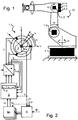
- Fig. 1 shows a six-axis articulated arm robot 10 with drive motors symbolized in black in the form of permanent magnet synchronous motors 1.1, ... 1.6, which actuate axes of movement whose positions q 1 , q 2 , ... determine the pose of the robot 10.
- Fig. 2 shows such a drive motor 1.1 with a stator 2, which has three windings with the currents I U , I V and I W , and a permanent magnet rotor 3, the rotor magnetic field orientation of which is described with respect to the stator 2 by the rotor angle ⁇ 1 .
- the rotor and shaft angles ⁇ , q can be transformed into one another in accordance with a gear ratio, possibly with the aid of a model, taking into account the elasticity of the gear.
- the motor controls M determine a setpoint current supply I qd, I dd in a reference system rotating with the rotor 3 for a constant predetermined drive motor torque ⁇ d , for example on the basis of a proportional-integral control law.
- the robot controller R can also specify new target angles ⁇ 1d , ⁇ 2d , ... for the drive motors, for example by corresponding backward transformation of a given Cartesian position and orientation of the TCPs of the robot 10, and the motor controllers M from this, taking into account the drive -Actual positions ⁇ 1 , ⁇ 2 , ...
- I qd P ⁇ ⁇ d with a proportionality factor P (cf. the dashed transmission of actual drive Positions ⁇ 1 in Fig. 2 ).
- a current control S determines a target current I ad , I bd in a virtual stator-fixed reference system from the target current supply I qd, I dd in the reference system rotating with the rotor 3 by means of a Clarke-Park transformation.
- the stator magnetic field which is to be applied to implement the commanded change in position according to motor control M, is opposite to the control commutation angle ⁇ rotated to a reference orientation that can be determined once in advance using "Wake &Shake", for example.
- Current and / or motor control can each be implemented entirely or partially in servo electronics of the respective drive motor. Equally, the current and / or motor control can also be implemented at least partially together with the robot control, for example in a control cabinet or a PC.
- control commutation angle ⁇ according to the current control law of the (present constant) drive motor torque ⁇ d , the commanded setpoint current supply I qd, I dd in the reference system rotating with the rotor 3 and the actual drive position ⁇ 1 depends. If, for example, the actual drive position ⁇ 1 is to be retained, the commutation angle ⁇ or the orientation of the stator rotating field must also be retained, its strength or the amplitude of the currents I a , I b determining the constant drive motor torque ⁇ d .
- control commutation angle is specified as the commutation angle by the current controller and implemented in a pulse-width-modulated manner in a converter 6.
- limit values for accelerations of the rotor and / or commutation angle and / or for higher time derivatives can be specified in an analogous manner in addition or as an alternative.
Landscapes
- Engineering & Computer Science (AREA)
- Power Engineering (AREA)
- Control Of Motors That Do Not Use Commutators (AREA)
- Control Of Ac Motors In General (AREA)
- Control Of Stepping Motors (AREA)
Description
- Die vorliegende Erfindung betrifft ein Verfahren und eine Vorrichtung zur Überwachung einer bewegungsgesteuerten Maschine, insbesondere eines Roboters, mit einem elektronisch kommutierten Antriebsmotor, dessen Ist-Position erfasst wird und für den ein Kommutierungswinkel auf Basis seiner erfassten Ist-Position und einer Steuergröße, insbesondere einer vorgegebenen Soll-Position, vorgegeben wird.
- Maschine mit einer Bewegungssteuerung, i.e. einer durch eine Steuerung vorgegebenen Bewegung, wie insbesondere ein- oder mehrachsige Roboter, weisen häufig einen oder mehrere Servoantriebe auf, die auf die jeweiligen Bewegungsachsen wirken.
- Solche Servoantriebe umfassen einen elektronisch kommutierten Elektromotor, beispielsweise einen permanenterregten Synchronmotor, sowie einen Umrichter zur Erzeugung eines drehenden Statorfeldes, dem der permanenterregte Rotor folgt und so ein gewünschtes Drehmoment bzw. eine gewünschte Achsposition liefert. Hierzu wird der Kommutierungswinkel vorgegeben, der die Orientierung des drehenden Statorfeldes bestimmt. Er hängt unter anderem von der Ist-Position des Rotors, i.e. dessen Orientierung ab, die beispielsweise über Hall-Sensoren oder die Induktion in stromlosen Statorwicklungen erfasst werden kann. Zum Beispiel aus der
EP 1 734 648 A1 ,DE 103 30 551 B4 undDE 10 2007 040 560 A1 sind Ansteuerungen elektronisch kommutierter Elektromotoren unter Vorgabe eines Winkels für das Statorfeld bekannt. - Die Servoelektronik, die dies durchführt und die Statorwicklungen in der erforderlichen Weise bestromt, wird von einer übergeordneten Maschinensteuerung angesteuert, die auf Basis der Bewegungssteuerung für die Maschine eine Steuergröße für den Antriebsmotor vorgibt. Beispielsweise kann eine Robotersteuerung getaktet neue Soll-Winkellagen für die Antriebsmotoren eines Roboters vorgeben, um programmierte Soll-Posen abzufahren.
- Insbesondere bei Manipulatoren wie etwa Industrierobotern soll sichergestellt werden, dass sie beispielsweise vorgegebene Geschwindigkeitsbegrenzungen einzelner Achsen oder eines Referenzpunktes wie des TCPs ("Toll Center Point") nicht überschreiten. Dies wird heute durch entsprechende Geschwindigkeitsüberwachungen in der Robotersteuerung sichergestellt, die Ist-Positionen oder -Geschwindigkeiten erfasst, diese - gegebenenfalls nach entsprechender Zeitdifferenzierung - mit vorgegebenen Geschwindigkeitsbegrenzungen vergleicht und bei Überschreiten der Begrenzungen Fehlerreaktionen auslöst, etwa den Roboter sicher stillsetzt.
- Nachteilig bedingt diese Überwachung in der übergeordneten Robotersteuerung sich kumulierende Reaktionszeiten zwischen dem Überschreiten einer Geschwindigkeitsbegrenzungen und der entsprechenden Reaktion, so dass es insbesondere zu einem unerwünschtem Nachlauf des Roboters kommt, dem beispielsweise mit entsprechend vergrößerten Schutzräumen Rechnung getragen werden muss.
- Aufgabe der vorliegenden Erfindung ist es, eine verbesserte Überwachung einer bewegungsgesteuerten Maschine wie beispielsweise eines Manipulators, insbesondere eines Roboters, zur Verfügung zu stellen.
- Aus der
EP 1 589 653 A2 ist eine Vorrichtung zum Betrieb eines Synchronmotors bekannt, die eine erste Überwachungseinrichtung zur Überprüfung eines Grenzwertes der Geschwindigkeit des Synchronmotors und eine zweite Überwachungseinrichtung zur Überprüfung eines Grenzwertes des Kommutierungswinkels des Synchronmotors oder dessen zeitlicher Änderung aufweist, mittels der in einer Ausführung die Änderung des Kommutierungswinkels pro Zeiteinheit auf einen entsprechenden Wert begrenzt wird. - Diese Aufgabe wird durch ein Verfahren mit den Merkmalen des Anspruchs 1 gelöst. Anspruch 6 stellt eine Vorrichtung, Anspruch 8 ein Computerprogrammprodukt, insbesondere einen Datenträger bzw. ein maschinenlesbares Speichermedium, zur Durchführung eines erfindungsgemäßen Verfahrens unter Schutz. Die Unteransprüche betreffen vorteilhafte Weiterbildungen.
- Erfindungsgemäß wird die Tatsache genutzt, dass bei einem elektronisch kommutierten Antriebsmotor die von ihm abgegebene Antriebskraft unter anderem von dem vorgegebenen Kommutierungswinkel abhängt.
- Wird also der Kommutierungswinkel derart vorgegeben, dass eine Änderungsrate des Kommutierungswinkels einen Grenzwert nicht überschreitet, so reduziert sich bei einem Überschreiten dieses Grenzwertes die die Maschine aktuierende Antriebskraft des Antriebsmotors automatisch, gegebenenfalls bis auf Null oder sogar darüber hinaus auf eine rückstellende Bremskraft. Dies kann zudem in einer Antriebssteuerung rascher erfolgen als in einer übergeordnete Maschinensteuerung, so dass vorteilhafterweise unerwünschte Reaktionsverzögerungen bzw. Nachlaufwege reduziert werden können.
- Auf der anderen Seite kann der Antriebsmotor vorteilhafterweise die volle Antriebskraft, beispielsweise ein Motorsollmoment, zur Verfügung stellen, solange die Änderungsrate den Grenzwert nicht überschreitet. Dies ist insbesondere bei Robotermanipulationen in eng begrenzten, sensiblen Arbeitsräumen von Vorteil wie sie beispielsweise bei Medizinrobotern, insbesondere chirurgischen Robotern auftreten.
- So kann zum Beispiel ein kommandiertes, von den Antriebsmotoren geleistetes Überschreiten eines Geschwindigkeits- oder Beschleunigungsgrenzwertes durch entsprechende Vorgabe eines Grenzwertes für die Kommutirungswinkelgeschwindigkeit zw. -beschleunigung verhindert werden, während innerhalb der zulässigen Grenzwerte die vollen Antriebskräfte zur Verfügung stehen.
- Gemäß einer bevorzugten Ausführung der vorliegenden Erfindung gibt zur Bewegungssteuerung einer Maschine, insbesondere eines ein- oder mehrachsigen Manipulators, vorzugsweise eines Roboters, eine übergeordnete Maschinensteuerung Steuergrößen für deren Antriebsmotor vor. Dabei wird vorliegend zur kompakteren Darstellung auch eine Regelung, i.e. die Ausgabe von Stellgrößen auf Basis vorgegebener Soll- und erfasster Ist-Größen, verallgemeinernd als Steuerung bezeichnet.
- Beispielsweise kann eine Robotersteuerung aus einer vorab geteachten Bahn getaktet neue Soll-Posen des Roboters ermitteln und entsprechende Soll-Positionen, etwa Soll-Drehwinkel der Gelenke eines Knickarmroboters oder Soll-Stellungen von Linearmotoren eines Portalroboters, bestimmen. Gleichermaßen kann eine Kraftregelung, beispielsweise modellgestützt, Soll-Antriebskräfte vorgeben, wobei zur kompakteren Darstellung auch ein antiparalleles Kräftepaar, i.e. ein Drehmoment, verallgemeinernd als Kraft bezeichnet wird. Stell- bzw. Steuergrößen können beispielsweise absolut oder als Differenz zu einem Ist-Wert, vorgegeben werden.
- Auf Basis vorgegebener Steuergrößen und einer erfassten Ist-Position für einen Antriebsmotor gibt in einer bevorzugten Ausführung eine Motorsteuerung ein Rotorfeld vor, beispielsweise Soll-Werte für die Stromkomponenten Id ("direct", i.e. in Richtung des Rotormagnetfeldes) und Iq ("quadrature", i.e. senkrecht hierzu) in Feldkoordinaten des Rotors des Antriebsmotors.
- Um diese zu bewirken, kann eine Stromsteuerung ein Statorfeld vorgeben, beispielsweise Soll-Werte für die Stromkomponenten Ia, Ib in (ggfs. virtuellen) Wicklungen eines Stators. Diese können durch einen Umrichter, insbesondere pulsweitenmoduliert, realisiert werden.
- Insbesondere ein Winkel der Orientierung eines solchen Statorfeldes relativ zu einem inertialen, beispielsweise statorfesten, Bezugssystem wird als Kommutierungswinkel bezeichnet.
- Bei einer bevorzugten Ausführung als permanenterregter Synchronmaschine läuft der permanenterregte Rotor mit dem mit diesem Kommutierungswinkel umlaufenden Statordrehfeld mit, so dass durch eine erfindungsgemäße Begrenzung einer Änderungsrate des Kommutierungswinkels wie vorstehend erläutert die aktuierte, durch den Antriebsmotor getriebene, Bewegung auf eine vorgegeben Änderungsrate begrenzt werden kann, oberhalb der der Antriebsmotor nur noch geringer, vorzugsweise gar nicht mehr beschleunigend und besonders bevorzugt sogar bremsend wirkt.
- Entsprechend wird erfindungsgemäß zur Überwachung, beispielsweise vorab oder während des Betriebs durch die Maschinensteuerung, ein fester oder variabler Grenzwert für eine Änderungsrate der Ist-Position des Antriebesmotors vorgegeben. Eine solche Änderungsrate kann insbesondere eine Änderung der Ist-Position über der Zeit, i.e. eine Geschwindigkeit, und/oder eine Zeitableitung hiervon, zum Beispiel eine Beschleunigung sein. Sie kann sich beispielsweise durch Rücktransformation auf Gelenkwinkelebene aus einer vorgegebenen kartesischen Maximalgeschwindigkeit des TCPs oder aber durch direkte Vorgabe von Antriebsmotorgeschwindigkeiten, - beschleunigungen, -rucken und dergleichen ergeben.
- Aus diesem Grenzwert für die Änderungsrate der Ist-Position des Antriebesmotors kann, wiederum beispielsweise vorab oder während des Betriebs, ein Grenzwert für eine entsprechende Änderungsrate des Kommutierungswinkels bestimmt werden. Dieser kann beispielsweise proportional zum Änderungsratengrenzwert für die Ist-Position des Antriebesmotors sein, wobei ein Proportionalitätsfaktor insbesondere eine Polpaarzahl des Antriebsmotors sein oder diese als multiplikativen Faktor enthalten kann.
- Erfindungsgemäß wird nun der Kommutierungswinkel derart vorgegeben, dass ein hierfür beispielsweise wie vorstehend erläutert vorgegebener Änderungsratengrenzwert nicht überschritten wird. Insbesondere kann somit ein Grenzwert für eine Kommutierungswinkelgeschwindigkeit, mit der ein Statordrehfeld umläuft, eine Kommutierungswinkelbeschleunigung, einen Kommutierungswinkelruck und/oder höhere Zeitableitungen vorgegeben werden.
- In einer bevorzugten Ausführung wird auf Basis der erfassten Antriebsmotor-Ist-Position und der vorgegebenen Steuergröße ein Steuer-Kommutierungswinkel oder eine Steuer-Kommutierungswinkeländerung derart bestimmt, dass die vorgegebene Steuergröße erreicht wird. Beispielsweise kann bei einer kommandierten neuen Antriebsmotorwinkel-Soll-Position bzw. einer kommandierten Soll-Antriebsmotorwinkeländerung mit vorgegebenem Sollantriebsmotorkraft der zugehörige Kommutierungswinkel bzw. die zugehörige Kommutierungswinkeländerung bestimmt werden.
- In der bevorzugten Ausführung wird dieser Steuer-Kommutierungswinkel nur dann als im Antriebsmotor zu realisierender Kommutierungswinkel vorgegeben bzw. dieser aufgrund der Steuer-Kommutierungswinkeländerung vorgegeben, wenn die Änderung gegenüber dem aktuellen Ist- Kommutierungswinkel den Grenzwert für die Änderungsrate nicht überschreitet.
- Überschreitet hingegen die Änderung bzw. Änderungsrate bei Umsetzung des auf Basis der kommandierten Steuergröße bestimmten Steuer-Kommutierungswinkel bzw. der auf Basis der kommandierten Steuergröße bestimmten Steuer-Kommutierungswinkeländerung den Grenzwert, so kann in einer bevorzugten Ausführung stattdessen ein konstanter Kommutierungswinkel vorgeben werden.
- Vorteilhaft kann dies eine positionsabhängige Pendelkraft zwischen einer Soll-Antriebskraft und ihrem Negativwert bewirken.
- Gleichermaßen kann ein Kommutierungswinkel vorgeben werden, der gegenüber der erfassten Antriebsmotor-Ist-Position um einen vorgegegeben, insbesondere konstanten Wert verschoben ist. Die Verschiebung kann vorteilhaft derart gewählt werden, dass der Antriebsmotor der Bewegung bremsend entgegenwirken.
- Ein Kommutierungswinkel kann alternativ auch auf Basis eines Ist-Kommutierungswinkels und eines zulässigen Maximaländerungswertes für den Kommutierungswinkel vorgeben werden, so dass eine Änderungsrate des Kommutierungswinkels auf diesen Maximaländerungswert begrenzt ist. Vorteilhaft kann dies ebenfalls eine Pendelkraft zwischen einer Soll-Antriebskraft und ihrem Negativwert bewirken.
- Neben dem Kommutierungswinkel kann, insbesondere durch Vorgabe der Amplitude der Stromkomponente Iq, auch die Soll-Antriebskraft des Antriebsmotors, bei einem Drehmotor entsprechend sein Drehmoment, vorgegeben werden. In einer bevorzugten Ausführung der vorliegenden Erfindung wird diese Amplitude konstant vorgegeben.
- Weitere Vorteile und Merkmale ergeben sich aus den Unteransprüchen und den Ausführungsbeispielen. Hierzu zeigt, teilweise schematisiert:
- Fig. 1:
- einen Knickarmroboter; und
- Fig. 2:
- eine Steuerung des Knickarmroboters mit einer Vorrichtung zur Überwachung nach einer Ausführung der vorliegenden Erfindung.
-
Fig. 1 zeigt einen sechsachsigen Knickarmroboter 10 mit schwarz symbolisierten Antriebsmotoren in Form permanentmagneterregter Synchronmotoren 1.1,...1.6, die Bewegungsachsen aktuieren, deren Positionen q1, q2,... die Pose des Roboters 10 bestimmen. -
Fig. 2 zeigt einen solchen Antriebsmotor 1.1 mit einem Stator 2, der drei Wicklungen mit den Strömen IU, IV und IW aufweist, und einem permanentmagneterregten Rotor 3, dessen Rotormagnetfeldorientierung gegenüber dem Stator 2 durch den Rotorwinkel ϕ1 beschrieben wird. Rotor- und Achswinkel ϕ, q können entsprechend einer Getriebeübersetzung, gegebenenfalls modellgestützt unter Berücksichtigung einer Elastizität des Getriebes, ineinander transformiert werden. - Eine Robotersteuerung R erhält zum einen, beispielsweise aus einer Bahnplanung, Soll-Positionen q d = (q 1d,..., q 6d) und zum anderen, beispielsweise mittels Hall-Sensoren, Encodern oder Resolvern 4, oder sensorlos durch Auswertung einer Induktion in jeweils stromlosen Statorwicklungen der Antriebsmotoren, Antriebs-Ist-Positionen ϕ1, ϕ2, ... bzw. Achs-Ist-Positionen q1, q2, ... und bestimmt hieraus Steuergrößen, beispielsweise Soll-Winkeländerungen Δϕ1d, Δϕ2d,... der einzelnen Antriebsmotoren und gibt diese an Motorsteuerungen M für die verschiedenen Antriebsmotoren 1.1, 1.2,... aus.
- Die Motorsteuerungen M bestimmen hieraus für ein konstant vorgegebenes Antriebsmotordrehmoment τd jeweils eine Soll-Bestromung Iqd, Idd in einem mit dem Rotor 3 drehenden Bezugssystem, beispielsweise auf Basis eines Proportional-Integral-Regelgesetzes. Gleichermaßen kann beispielsweise auch die Robotersteuerung R, etwa durch entsprechende Rückwärtstransformation einer vorgegebenen kartesischen Lage und Orientierung des TCPs des Roboters 10, neue Soll-Winkel ϕ1d, ϕ2d,... für die Antriebsmotoren vorgeben und die Motorsteuerungen M hieraus unter Berücksichtigung der Antriebs-Ist-Positionen ϕ1, ϕ2, ... wiederum Soll-Bestromungen Iqd, Idd, bestimmen, vereinfacht beispielsweise gemäß Iqd = P × Δϕd mit einem Proportionalitätsfaktor P (vgl. die gestrichelte Übertragung von Antriebs-Ist-Positionen ϕ1 in
Fig. 2 ). - Eine Stromsteuerung S bestimmt mittels einer Clarke-Park-Transformation aus der Soll-Bestromung Iqd, Idd in dem mit dem Rotor 3 drehenden Bezugssystem eine Soll-Bestromung Iad, Ibd in einem virtuellen statorfesten Bezugssystem. In diesem ist das Statormagnetfeld, das zur Realisierung der kommandierten Positionsänderung gemäß Motorsteuerung M anzulegen ist, um den Steuer-Kommutierungswinkel δ gegenüber einer Bezugsorientierung verdreht, die beispielsweise einmalig vorab mittels "Wake&Shake" ermittelt werden kann.
- Strom- und/oder Motorsteuerung können jeweils ganz oder teilweise in einer Servoelektronik des jeweiligen Antriebsmotors implementiert sein. Gleichermaßen kann die Strom- und/oder Motorsteuerung auch wenigstens teilweise zusammen mit der Robotersteuerung beispielsweise in einem Steuerschrank oder einem PC implementiert sein.
- Man erkennt, dass der Steuer-Kommutierungswinkel δ gemäß dem Stromsteuerungs-Regelgesetz von dem (vorliegend konstanten) Antriebsmotordrehmoment τd, der kommandierten Soll-Bestromung Iqd, Idd in dem mit dem Rotor 3 drehenden Bezugssystem und der Antriebs-Ist-Position ϕ1 abhängt. Soll beispielsweise die Antriebs-Ist-Position ϕ1 beibehalten werden, muss auch der Kommutierungswinkel δ bzw. die Orientierung des Statordrehfeldes beibehalten werden, wobei dessen Stärke bzw. die Amplitude der Ströme Ia, Ib das konstante Antriebsmotordrehmoment τd bestimmen.
- Nun vergleicht eine erfindungsgemäße Kommutierungswinkelbegrenzungseinrichtung 5, ob eine Änderungsrate des von der Motorsteuerung M kommandierten Steuer-Kommutierungswinkels einen vorgegebenen Grenzwert ω1, max überschreitet, der beispielsweise einmalig vorab gemäß ω1, max = C × dϕ1, max/dt aus einer Drehwinkelgeschwindigkeitsbegrenzung dϕ1, max/dt mit einer Proportionalitätskonstanten C bestimmt wurde, die den Kehrwert der Polpaarzahl des Antriebsmotors 1.1 enthält.
- Ist dies nicht der Fall, i.e. überschreitet eine Änderungsrate dϕ1/dt des dem sich mit ω1 drehenden Statorfeldes folgender Rotor 3 den hierfür vorgegebene Grenzwert nicht, wird der Steuer-Kommutierungswinkel von der Stromsteuerung als Kommutierungswinkel vorgegeben und in einem Umrichter 6 pulsweitenmoduliert umgesetzt.
- Ändert sich hingegen der kommandierte Steuer-Kommutierungswinkel rascher als der Grenzwert ω1, max dies zulässt, i.e. würde das Statormagnetfeld sich zu schnell drehen, wenn die von der Motorsteuerung kommandierte Soll-Bestromung Iqd, Idd umgesetzt würde, so wird stattdessen beispielsweise der Kommutierungswinkel δ um einen vorgegebenen Betrag δ0 gegenüber dem Rotorwinkel verschoben als

- Man erkennt, dass, solange die Geschwindigkeitsbegrenzung in der Stromsteuerung S eingehalten wird, das Antriebsmotordrehmoment τd zur Einstellung der kommandierten Antriebssollposition zur Verfügung steht, während bei einem Überschreiten der Geschwindigkeitsbegrenzung automatisch und ohne Verzögerung durch die Kaskadierung von Roboter-, Motor- und Stromsteuerung R, M bzw. S bremsend auf den Rotor 3 eingewirkt wird.
- Anstelle der Verschiebung des Kommutierungswinkels gegenüber der Antriebs-Ist-Position ϕ1 kann beispielsweise bei Überschreiten des Grenzwertes ω1,max durch den Steuer-Kommutierungswinkel auch ein konstanter Kommutierungswinkel δ = const oder ein sich mit der maximal zulässigen Änderungsrate ändernder Kommutierungswinkel δ(t + Δt) = δ(t) + ω1, max × Δt vorgegeben werden, um ein Pendelantriebsmoment ±τd zu bewirken.
- Obgleich im vorstehenden Ausführungsbeispiel ein Grenzwerte für Geschwindigkeiten vorgegeben wurden, können in analoger Weise zusätzlich oder alternativ Grenzwerte für Beschleunigungen des Rotors und/oder Kommutierungswinkels und/oder für höhere Zeitableitungen vorgegeben werden.
-
- 1.1 - 1.6
- Antriebsmotor (permanenterregter Synchronmotor)
- 2
- Stator mit Drehfeldwicklung
- 3
- Permanentmagnet-Rotor
- 4
- Resolver
- 5
- Kommutierungswinkelbegrenzungseinrichtung
- 6
- Umrichter
- 10
- Industrieroboter
- M1
- Motorsteuerung
- R
- Robotersteuerung
- S1
- Stromsteuerung
- IU, IV, IW,
- Strom in Statorwicklung
- Idd, IVq
- Soll-Strom in Rotorfeldkoordinaten
- Iad, Iaq
- Soll-Strom in Statorkoordinaten
- ϕ1, ϕ2,...
- Ist-Position eines Antriebsmotors (Rotors)
- q1(d), q2(d),...
- Ist(Soll)-Position einer Bewegungsachse
- δ
- Kommutierungswinkel zwischen Statordrehfeld und inertialem Bezugssystem
Claims (8)
- Verfahren zur Überwachung einer bewegungsgesteuerten Maschine, insbesondere eines Manipulators (10), mit einem elektronisch kommutierten Antriebsmotor (1.1 - 1.6), für den ein Kommutierungswinkel (δ) auf Basis seiner erfassten Ist-Position (ϕ1, ϕ2,...) und einer Steuergröße, insbesondere einer vorgegebenen Soll-Position (q1d, q2d....) vorgegeben wird, mit dem Schritt:Vorgeben eines Grenzwertes für eine Änderungsrate, insbesondere eine Zeitableitung, der Ist-Position des Antriebesmotors;dadurch gekennzeichnet, dassder Kommutierungswinkel derart vorgegeben wird, dass eine Änderungsrate (ω1 = dδ1/dt) des Kommutierungswinkels einen Grenzwert (ω1, max) nicht überschreitet, wobei auf Basis der erfassten Antriebsmotor-Ist-Position und der vorgegebenen Steuergröße ein Steuer-Kommutierungswinkel oder eine Steuer-Kommutierungswinkeländerung bestimmt wird und , falls eine Änderungsrate des Steuer-Kommutierungswinkels bzw. der Steuer-Kommutierungswinkeländerung den Grenzwert für den Kommutierungswinkel überschreitet, ein konstanter Kommutierungswinkel vorgeben wird oderein gegenüber der erfassten Antriebsmotor-Ist-Position um einen vorgegebenen, insbesondere konstanten, Wert (δ0) verschobener Kommutierungswinkel vorgeben wird oderein Kommutierungswinkel auf Basis eines Ist-Kommutierungswinkels und eines Maximaländerungswertes für den Kommutierungswinkel vorgeben wird
- Verfahren nach dem vorhergehenden Anspruch, dadurch gekennzeichnet, dass der Kommutierungswinkel für eine vorgegebene, insbesondere konstante, Antriebskraft (τd) des Antriebsmotors vorgegeben wird.
- Verfahren nach einem der vorhergehenden Ansprüche, dadurch gekennzeichnet, dass eine Ist-Position (ϕ1) des Antriebesmotors sensorgestützt (4) oder sensorlos erfasst wird.
- Verfahren nach einem der vorhergehenden Ansprüche, gekennzeichnet durch eine Block-, Sinus- oder Feldkommutierung.
- Verfahren nach einem der vorhergehenden Ansprüche, dadurch gekennzeichnet, dass eine Änderungsrate eine Geschwindigkeit und/oder Beschleunigung umfasst.
- Vorrichtung (R, M, S) zur Überwachung einer bewegungsgesteuerten Maschine, insbesondere eines Manipulators (10), mit einem elektronisch kommutierten Antriebsmotor (1.1 - 1.6),
gekennzeichnet durch
eine Kommutierungswinkelbegrenzungseinrichtung (5) zur Durchführung eines Verfahrens nach einem der vorhergehenden Ansprüche. - Vorrichtung nach Anspruch 6, gekennzeichnet durch eine Maschinensteuerung (R) zur Vorgabe einer Steuergröße, insbesondere einer Soll-Position, für den Antriebsmotor, eine Motorsteuerung (M) zur Vorgabe eines Rotorfeldes, eine Stromsteuerung (S) zur Vorgabe eines Statorfeldes und/oder einen Umrichter (6) zur, insbesondere pulsweitenmodulierten, Ansteuerung einer Statorwicklung (2).
- Computerprogrammprodukt mit Programmcode, der auf einem maschinenlesbaren Träger gespeichert ist und ein Verfahren nach einem der vorhergehenden Ansprüche 1 bis 5 ausführt, wenn es in einer Vorrichtung nach Anspruch 6 oder 7 abläuft.
Applications Claiming Priority (1)
| Application Number | Priority Date | Filing Date | Title |
|---|---|---|---|
| DE102010024238A DE102010024238A1 (de) | 2010-06-18 | 2010-06-18 | Verfahren und Vorrichtung zur Überwachung einer bewegungsgesteuerten Maschine mit einem elektronisch kommutierten Antriebsmotor |
Publications (3)
| Publication Number | Publication Date |
|---|---|
| EP2398143A2 EP2398143A2 (de) | 2011-12-21 |
| EP2398143A3 EP2398143A3 (de) | 2017-08-02 |
| EP2398143B1 true EP2398143B1 (de) | 2021-08-18 |
Family
ID=44719017
Family Applications (1)
| Application Number | Title | Priority Date | Filing Date |
|---|---|---|---|
| EP11004938.4A Active EP2398143B1 (de) | 2010-06-18 | 2011-06-16 | Verfahren und Vorrichtung zur Überwachung einer bewegungsgesteuerten Maschine mit einem elektronisch kommutierten Antriebsmotor |
Country Status (3)
| Country | Link |
|---|---|
| US (1) | US8547047B2 (de) |
| EP (1) | EP2398143B1 (de) |
| DE (1) | DE102010024238A1 (de) |
Families Citing this family (8)
| Publication number | Priority date | Publication date | Assignee | Title |
|---|---|---|---|---|
| EP2243602B1 (de) * | 2009-04-22 | 2013-05-15 | KUKA Roboter GmbH | Verfahren und Vorrichtung zur Regelung eines Manipulators |
| JP5357300B1 (ja) | 2012-05-21 | 2013-12-04 | ファナック株式会社 | 永久磁石同期電動機におけるロータの磁極位置を検出する磁極位置検出装置 |
| DE102012213709A1 (de) * | 2012-08-02 | 2014-02-06 | Continental Automotive Gmbh | Verfahren zum Erkennen eines Fehlerfalls einer Motoranordnung mit einer elektrischen Maschine und Motorsteuergerät |
| DE102013220979A1 (de) | 2013-04-26 | 2014-11-13 | Continental Automotive Gmbh | Verfahren und Vorrichtung zum Betrieb eines bürstenlosen Gleichstrommotors |
| US9093933B2 (en) | 2013-08-27 | 2015-07-28 | GM Global Technology Operations LLC | Method and apparatus for monitoring rotational position of an electric machine |
| JP6423209B2 (ja) * | 2014-09-08 | 2018-11-14 | Dmg森精機株式会社 | 工作機械 |
| DE102014224122B4 (de) * | 2014-11-26 | 2018-10-25 | Siemens Healthcare Gmbh | Verfahren zum Betreiben eines robotischen Gerätes und robotisches Gerät |
| FR3054468B1 (fr) * | 2016-07-29 | 2018-08-31 | Staubli Faverges | Procede de commande d'un robot a usage industriel |
Family Cites Families (24)
| Publication number | Priority date | Publication date | Assignee | Title |
|---|---|---|---|---|
| US4074179A (en) * | 1975-06-16 | 1978-02-14 | Warner Electric Brake & Clutch Company | Position detection methods and apparatus for stepping motors |
| US4992710A (en) * | 1989-09-27 | 1991-02-12 | Seagate Technology, Inc. | Position detection for a brushless DC motor with sample time optimization |
| US5200683A (en) * | 1992-01-30 | 1993-04-06 | Siemens Industrial Automation, Inc. | Method for optimizing sampling rates for position tracking for motion control systems |
| JP3084928B2 (ja) * | 1992-05-29 | 2000-09-04 | 三菱電機株式会社 | 電動機の位置制御装置 |
| US5475291A (en) * | 1992-12-10 | 1995-12-12 | Matsushita Electric Industrial Co., Ltd. | Adjustment device for adjusting control parameters of a servo motor and an adjustment method therefor |
| DE4442151A1 (de) * | 1994-11-26 | 1996-05-30 | Philips Patentverwaltung | Schaltungsanordnung zum Steuern eines elektronisch kommutierten Motors |
| JP3625901B2 (ja) * | 1995-06-30 | 2005-03-02 | 三菱電機株式会社 | サーボ制御システムの自動適正化方法および装置 |
| JP4060393B2 (ja) * | 1996-01-24 | 2008-03-12 | 三菱電機株式会社 | ロボットの速度演算装置、およびロボットの速度演算方法 |
| WO1998026905A1 (fr) * | 1996-12-19 | 1998-06-25 | Honda Giken Kogyo Kabushiki Kaisha | Controleur d'attitude de robot mobile sur jambes |
| US6172498B1 (en) * | 1998-09-29 | 2001-01-09 | Rockwell Technologies, Llc | Method and apparatus for rotor angle detection |
| JP3442340B2 (ja) * | 2000-03-29 | 2003-09-02 | ファナック株式会社 | モータ制御装置 |
| DE10041606B4 (de) * | 2000-08-24 | 2008-07-24 | Berger Lahr Gmbh & Co. Kg | Elektromotorischer Antrieb und Verfahren zum Betreiben eines elektronisch kommutierten Elektromotors |
| WO2003043172A1 (en) * | 2001-11-12 | 2003-05-22 | International Rectifier Corporation | Rotor angle estimation for permanent magnet synchronous motor drive |
| DE10308859A1 (de) * | 2003-02-27 | 2004-09-16 | Melexis Gmbh | Verfahren zur leistungsoptimalen Ansteuerung von BLDC-Motoren |
| DE10330551B4 (de) | 2003-07-05 | 2005-07-21 | Fachhochschule Flensburg | Bestimmung der Startkommutierung in Synchron-Servo-Antrieben |
| EP1652634B1 (de) * | 2003-07-29 | 2011-12-28 | Panasonic Corporation | Roboterarmsteuerverfahren und -steuervorrichtung |
| DE112004001967A5 (de) * | 2003-11-06 | 2012-03-22 | Continental Teves Ag & Co. Ohg | Verfahren zur Ermittlung der Rotorlage einer Synchronmaschine |
| DE102004019284A1 (de) * | 2004-04-21 | 2005-11-10 | Aradex Ag | Vorrichtung zum Betrieb eines Synchronmotors |
| DE102004054504B4 (de) * | 2004-11-11 | 2011-08-18 | Minebea Co., Ltd. | Verfahren zur automatischen Einstellung des Kommutierungswinkels bei bürstenlosen Gleichstrommotoren |
| JP2006201148A (ja) * | 2004-12-22 | 2006-08-03 | Toshiba Mach Co Ltd | 信号処理装置、信号処理方法、信号処理プログラム、信号処理プログラムを記録した記録媒体、速度検出装置、サーボ機構 |
| EP1734648B1 (de) | 2005-06-13 | 2012-08-15 | Brose Fahrzeugteile GmbH & Co. KG, Würzburg | Asymmetrische Ansteuerung eines sensorlosen und bürstenlosen Elektromotors |
| DE102007017285A1 (de) * | 2007-04-12 | 2008-11-06 | Robert Bosch Gmbh | Verfahren und Vorrichtung zum Überwachen von Drehstrommaschinen |
| DE102007040560A1 (de) | 2007-08-28 | 2009-03-12 | Continental Automotive Gmbh | Verfahren zur Ansteuerung eines Umrichters sowie zugehörige Vorrichtung |
| US8324851B2 (en) * | 2009-03-04 | 2012-12-04 | Rockwell Automation Technologies, Inc. | Method for determining a rotor position in a permanent magnet motor |
-
2010
- 2010-06-18 DE DE102010024238A patent/DE102010024238A1/de not_active Ceased
-
2011
- 2011-06-16 EP EP11004938.4A patent/EP2398143B1/de active Active
- 2011-06-17 US US13/162,827 patent/US8547047B2/en active Active
Also Published As
| Publication number | Publication date |
|---|---|
| EP2398143A2 (de) | 2011-12-21 |
| EP2398143A3 (de) | 2017-08-02 |
| US20110309782A1 (en) | 2011-12-22 |
| DE102010024238A1 (de) | 2011-12-22 |
| US8547047B2 (en) | 2013-10-01 |
Similar Documents
| Publication | Publication Date | Title |
|---|---|---|
| EP2398143A2 (de) | Verfahren und Vorrichtung zur Überwachung einer bewegungsgesteuerten Maschine mit einem elektronisch kommutierten Antriebsmotor | |
| DE2656433C3 (de) | Verfahren und Anordnung zur Regelung von Manipulatoen und industriellen Robotern | |
| DE102009049172A1 (de) | Verfahren und Vorrichtung zur Steuerung eines Manipulators | |
| EP2492062B1 (de) | Industrieroboter | |
| DE112010000768T5 (de) | Ventilsteuervorr!chtung | |
| DE4437793A1 (de) | Verfahren und Vorrichtung zur Steuerung eines Elektromotors | |
| EP2347309A1 (de) | Verfahren und vorrichtung zur sicheren erfassung einer kinematischen grösse eines manipulators | |
| DE102011001112A1 (de) | Verfahren und Steuerungseinrichtung zur schwingungsarmen Bewegung eines bewegbaren Kranelementes eines Kransystems | |
| DE102014003631A1 (de) | Motorsteuervorrichtung, die eine Spannungssättigung erkennt | |
| WO2023279132A1 (de) | Verfahren und vorrichtung zur bestimmung einer zeitoptimalen trajektorie | |
| EP3061576A1 (de) | Verfahren zur Optimierung eines Bewegungsprofils, Computerprogramm, Steuereinrichtung und technisches System | |
| EP0198248A2 (de) | Steuereinheit für einen von einem Frequenzumrichter gespeisten Drehstrommotorantrieb | |
| EP3464862B1 (de) | Verfahren und vorrichtung zur kalibrierung eines stellgebersystems | |
| EP3802013B1 (de) | Kraftregelung eines roboters | |
| DE102020125397A1 (de) | Motorsteuerung | |
| WO2018158181A1 (de) | Antriebssystem und dessen beurteilung | |
| DE102018207919B3 (de) | Robotersteuerung | |
| EP2033056B1 (de) | Verfahren zum steuern der bewegung eines aktuators | |
| DE102010015407A1 (de) | Roboter und Verfahren zum Betreiben eines Roboters | |
| JPH1153021A (ja) | 産業用ロボットの加減速パターン生成方法 | |
| EP3235677A1 (de) | Verfahren zur lagegeberlosen regelung eines elektroantriebs | |
| DE102008062979A1 (de) | Verfahren zur Positionierung eines Werkzeughalters | |
| EP3296755B1 (de) | Ermittlung von lastgrössen im laufenden betrieb | |
| EP4252089B1 (de) | Bewegungssteuerung eines objekts | |
| DE102019134121B3 (de) | Mobiler Roboter mit Impedanzregelung |
Legal Events
| Date | Code | Title | Description |
|---|---|---|---|
| AK | Designated contracting states |
Kind code of ref document: A2 Designated state(s): AL AT BE BG CH CY CZ DE DK EE ES FI FR GB GR HR HU IE IS IT LI LT LU LV MC MK MT NL NO PL PT RO RS SE SI SK SM TR |
|
| AX | Request for extension of the european patent |
Extension state: BA ME |
|
| PUAI | Public reference made under article 153(3) epc to a published international application that has entered the european phase |
Free format text: ORIGINAL CODE: 0009012 |
|
| RAP1 | Party data changed (applicant data changed or rights of an application transferred) |
Owner name: KUKA ROBOTER GMBH |
|
| PUAL | Search report despatched |
Free format text: ORIGINAL CODE: 0009013 |
|
| AK | Designated contracting states |
Kind code of ref document: A3 Designated state(s): AL AT BE BG CH CY CZ DE DK EE ES FI FR GB GR HR HU IE IS IT LI LT LU LV MC MK MT NL NO PL PT RO RS SE SI SK SM TR |
|
| AX | Request for extension of the european patent |
Extension state: BA ME |
|
| RIC1 | Information provided on ipc code assigned before grant |
Ipc: H02P 6/14 20160101AFI20170628BHEP Ipc: H02P 21/00 20160101ALI20170628BHEP |
|
| STAA | Information on the status of an ep patent application or granted ep patent |
Free format text: STATUS: REQUEST FOR EXAMINATION WAS MADE |
|
| 17P | Request for examination filed |
Effective date: 20180111 |
|
| RBV | Designated contracting states (corrected) |
Designated state(s): AL AT BE BG CH CY CZ DE DK EE ES FI FR GB GR HR HU IE IS IT LI LT LU LV MC MK MT NL NO PL PT RO RS SE SI SK SM TR |
|
| RAP1 | Party data changed (applicant data changed or rights of an application transferred) |
Owner name: KUKA DEUTSCHLAND GMBH |
|
| GRAP | Despatch of communication of intention to grant a patent |
Free format text: ORIGINAL CODE: EPIDOSNIGR1 |
|
| STAA | Information on the status of an ep patent application or granted ep patent |
Free format text: STATUS: GRANT OF PATENT IS INTENDED |
|
| RIC1 | Information provided on ipc code assigned before grant |
Ipc: H02P 6/14 20160101AFI20210215BHEP Ipc: H02P 6/15 20160101ALI20210215BHEP Ipc: H02P 21/00 20160101ALI20210215BHEP |
|
| INTG | Intention to grant announced |
Effective date: 20210304 |
|
| GRAS | Grant fee paid |
Free format text: ORIGINAL CODE: EPIDOSNIGR3 |
|
| GRAA | (expected) grant |
Free format text: ORIGINAL CODE: 0009210 |
|
| STAA | Information on the status of an ep patent application or granted ep patent |
Free format text: STATUS: THE PATENT HAS BEEN GRANTED |
|
| AK | Designated contracting states |
Kind code of ref document: B1 Designated state(s): AL AT BE BG CH CY CZ DE DK EE ES FI FR GB GR HR HU IE IS IT LI LT LU LV MC MK MT NL NO PL PT RO RS SE SI SK SM TR |
|
| REG | Reference to a national code |
Ref country code: GB Ref legal event code: FG4D Free format text: NOT ENGLISH |
|
| REG | Reference to a national code |
Ref country code: CH Ref legal event code: EP |
|
| REG | Reference to a national code |
Ref country code: DE Ref legal event code: R096 Ref document number: 502011017203 Country of ref document: DE |
|
| REG | Reference to a national code |
Ref country code: IE Ref legal event code: FG4D Free format text: LANGUAGE OF EP DOCUMENT: GERMAN Ref country code: AT Ref legal event code: REF Ref document number: 1422537 Country of ref document: AT Kind code of ref document: T Effective date: 20210915 |
|
| REG | Reference to a national code |
Ref country code: LT Ref legal event code: MG9D |
|
| REG | Reference to a national code |
Ref country code: NL Ref legal event code: MP Effective date: 20210818 |
|
| PG25 | Lapsed in a contracting state [announced via postgrant information from national office to epo] |
Ref country code: LT Free format text: LAPSE BECAUSE OF FAILURE TO SUBMIT A TRANSLATION OF THE DESCRIPTION OR TO PAY THE FEE WITHIN THE PRESCRIBED TIME-LIMIT Effective date: 20210818 Ref country code: BG Free format text: LAPSE BECAUSE OF FAILURE TO SUBMIT A TRANSLATION OF THE DESCRIPTION OR TO PAY THE FEE WITHIN THE PRESCRIBED TIME-LIMIT Effective date: 20211118 Ref country code: PT Free format text: LAPSE BECAUSE OF FAILURE TO SUBMIT A TRANSLATION OF THE DESCRIPTION OR TO PAY THE FEE WITHIN THE PRESCRIBED TIME-LIMIT Effective date: 20211220 Ref country code: NO Free format text: LAPSE BECAUSE OF FAILURE TO SUBMIT A TRANSLATION OF THE DESCRIPTION OR TO PAY THE FEE WITHIN THE PRESCRIBED TIME-LIMIT Effective date: 20211118 Ref country code: RS Free format text: LAPSE BECAUSE OF FAILURE TO SUBMIT A TRANSLATION OF THE DESCRIPTION OR TO PAY THE FEE WITHIN THE PRESCRIBED TIME-LIMIT Effective date: 20210818 Ref country code: FI Free format text: LAPSE BECAUSE OF FAILURE TO SUBMIT A TRANSLATION OF THE DESCRIPTION OR TO PAY THE FEE WITHIN THE PRESCRIBED TIME-LIMIT Effective date: 20210818 Ref country code: ES Free format text: LAPSE BECAUSE OF FAILURE TO SUBMIT A TRANSLATION OF THE DESCRIPTION OR TO PAY THE FEE WITHIN THE PRESCRIBED TIME-LIMIT Effective date: 20210818 Ref country code: HR Free format text: LAPSE BECAUSE OF FAILURE TO SUBMIT A TRANSLATION OF THE DESCRIPTION OR TO PAY THE FEE WITHIN THE PRESCRIBED TIME-LIMIT Effective date: 20210818 Ref country code: SE Free format text: LAPSE BECAUSE OF FAILURE TO SUBMIT A TRANSLATION OF THE DESCRIPTION OR TO PAY THE FEE WITHIN THE PRESCRIBED TIME-LIMIT Effective date: 20210818 |
|
| PG25 | Lapsed in a contracting state [announced via postgrant information from national office to epo] |
Ref country code: PL Free format text: LAPSE BECAUSE OF FAILURE TO SUBMIT A TRANSLATION OF THE DESCRIPTION OR TO PAY THE FEE WITHIN THE PRESCRIBED TIME-LIMIT Effective date: 20210818 Ref country code: LV Free format text: LAPSE BECAUSE OF FAILURE TO SUBMIT A TRANSLATION OF THE DESCRIPTION OR TO PAY THE FEE WITHIN THE PRESCRIBED TIME-LIMIT Effective date: 20210818 Ref country code: GR Free format text: LAPSE BECAUSE OF FAILURE TO SUBMIT A TRANSLATION OF THE DESCRIPTION OR TO PAY THE FEE WITHIN THE PRESCRIBED TIME-LIMIT Effective date: 20211119 |
|
| PG25 | Lapsed in a contracting state [announced via postgrant information from national office to epo] |
Ref country code: NL Free format text: LAPSE BECAUSE OF FAILURE TO SUBMIT A TRANSLATION OF THE DESCRIPTION OR TO PAY THE FEE WITHIN THE PRESCRIBED TIME-LIMIT Effective date: 20210818 |
|
| PG25 | Lapsed in a contracting state [announced via postgrant information from national office to epo] |
Ref country code: DK Free format text: LAPSE BECAUSE OF FAILURE TO SUBMIT A TRANSLATION OF THE DESCRIPTION OR TO PAY THE FEE WITHIN THE PRESCRIBED TIME-LIMIT Effective date: 20210818 |
|
| REG | Reference to a national code |
Ref country code: DE Ref legal event code: R097 Ref document number: 502011017203 Country of ref document: DE |
|
| PG25 | Lapsed in a contracting state [announced via postgrant information from national office to epo] |
Ref country code: SM Free format text: LAPSE BECAUSE OF FAILURE TO SUBMIT A TRANSLATION OF THE DESCRIPTION OR TO PAY THE FEE WITHIN THE PRESCRIBED TIME-LIMIT Effective date: 20210818 Ref country code: SK Free format text: LAPSE BECAUSE OF FAILURE TO SUBMIT A TRANSLATION OF THE DESCRIPTION OR TO PAY THE FEE WITHIN THE PRESCRIBED TIME-LIMIT Effective date: 20210818 Ref country code: RO Free format text: LAPSE BECAUSE OF FAILURE TO SUBMIT A TRANSLATION OF THE DESCRIPTION OR TO PAY THE FEE WITHIN THE PRESCRIBED TIME-LIMIT Effective date: 20210818 Ref country code: EE Free format text: LAPSE BECAUSE OF FAILURE TO SUBMIT A TRANSLATION OF THE DESCRIPTION OR TO PAY THE FEE WITHIN THE PRESCRIBED TIME-LIMIT Effective date: 20210818 Ref country code: CZ Free format text: LAPSE BECAUSE OF FAILURE TO SUBMIT A TRANSLATION OF THE DESCRIPTION OR TO PAY THE FEE WITHIN THE PRESCRIBED TIME-LIMIT Effective date: 20210818 Ref country code: AL Free format text: LAPSE BECAUSE OF FAILURE TO SUBMIT A TRANSLATION OF THE DESCRIPTION OR TO PAY THE FEE WITHIN THE PRESCRIBED TIME-LIMIT Effective date: 20210818 |
|
| PLBE | No opposition filed within time limit |
Free format text: ORIGINAL CODE: 0009261 |
|
| STAA | Information on the status of an ep patent application or granted ep patent |
Free format text: STATUS: NO OPPOSITION FILED WITHIN TIME LIMIT |
|
| 26N | No opposition filed |
Effective date: 20220519 |
|
| PG25 | Lapsed in a contracting state [announced via postgrant information from national office to epo] |
Ref country code: IT Free format text: LAPSE BECAUSE OF FAILURE TO SUBMIT A TRANSLATION OF THE DESCRIPTION OR TO PAY THE FEE WITHIN THE PRESCRIBED TIME-LIMIT Effective date: 20210818 |
|
| PG25 | Lapsed in a contracting state [announced via postgrant information from national office to epo] |
Ref country code: SI Free format text: LAPSE BECAUSE OF FAILURE TO SUBMIT A TRANSLATION OF THE DESCRIPTION OR TO PAY THE FEE WITHIN THE PRESCRIBED TIME-LIMIT Effective date: 20210818 |
|
| PG25 | Lapsed in a contracting state [announced via postgrant information from national office to epo] |
Ref country code: MC Free format text: LAPSE BECAUSE OF FAILURE TO SUBMIT A TRANSLATION OF THE DESCRIPTION OR TO PAY THE FEE WITHIN THE PRESCRIBED TIME-LIMIT Effective date: 20210818 |
|
| REG | Reference to a national code |
Ref country code: BE Ref legal event code: MM Effective date: 20220630 |
|
| REG | Reference to a national code |
Ref country code: FR Ref legal event code: PLFP Year of fee payment: 13 |
|
| PG25 | Lapsed in a contracting state [announced via postgrant information from national office to epo] |
Ref country code: LU Free format text: LAPSE BECAUSE OF NON-PAYMENT OF DUE FEES Effective date: 20220616 Ref country code: IE Free format text: LAPSE BECAUSE OF NON-PAYMENT OF DUE FEES Effective date: 20220616 |
|
| PG25 | Lapsed in a contracting state [announced via postgrant information from national office to epo] |
Ref country code: BE Free format text: LAPSE BECAUSE OF NON-PAYMENT OF DUE FEES Effective date: 20220630 |
|
| P01 | Opt-out of the competence of the unified patent court (upc) registered |
Effective date: 20230528 |
|
| REG | Reference to a national code |
Ref country code: AT Ref legal event code: MM01 Ref document number: 1422537 Country of ref document: AT Kind code of ref document: T Effective date: 20220616 |
|
| PG25 | Lapsed in a contracting state [announced via postgrant information from national office to epo] |
Ref country code: AT Free format text: LAPSE BECAUSE OF NON-PAYMENT OF DUE FEES Effective date: 20220616 |
|
| PG25 | Lapsed in a contracting state [announced via postgrant information from national office to epo] |
Ref country code: HU Free format text: LAPSE BECAUSE OF FAILURE TO SUBMIT A TRANSLATION OF THE DESCRIPTION OR TO PAY THE FEE WITHIN THE PRESCRIBED TIME-LIMIT; INVALID AB INITIO Effective date: 20110616 |
|
| PG25 | Lapsed in a contracting state [announced via postgrant information from national office to epo] |
Ref country code: MK Free format text: LAPSE BECAUSE OF FAILURE TO SUBMIT A TRANSLATION OF THE DESCRIPTION OR TO PAY THE FEE WITHIN THE PRESCRIBED TIME-LIMIT Effective date: 20210818 Ref country code: CY Free format text: LAPSE BECAUSE OF FAILURE TO SUBMIT A TRANSLATION OF THE DESCRIPTION OR TO PAY THE FEE WITHIN THE PRESCRIBED TIME-LIMIT Effective date: 20210818 |
|
| PG25 | Lapsed in a contracting state [announced via postgrant information from national office to epo] |
Ref country code: TR Free format text: LAPSE BECAUSE OF FAILURE TO SUBMIT A TRANSLATION OF THE DESCRIPTION OR TO PAY THE FEE WITHIN THE PRESCRIBED TIME-LIMIT Effective date: 20210818 |
|
| PGFP | Annual fee paid to national office [announced via postgrant information from national office to epo] |
Ref country code: GB Payment date: 20240402 Year of fee payment: 14 |
|
| PGFP | Annual fee paid to national office [announced via postgrant information from national office to epo] |
Ref country code: DE Payment date: 20240328 Year of fee payment: 14 |
|
| PGFP | Annual fee paid to national office [announced via postgrant information from national office to epo] |
Ref country code: FR Payment date: 20240408 Year of fee payment: 14 |
|
| PG25 | Lapsed in a contracting state [announced via postgrant information from national office to epo] |
Ref country code: MT Free format text: LAPSE BECAUSE OF FAILURE TO SUBMIT A TRANSLATION OF THE DESCRIPTION OR TO PAY THE FEE WITHIN THE PRESCRIBED TIME-LIMIT Effective date: 20210818 |
|
| PGFP | Annual fee paid to national office [announced via postgrant information from national office to epo] |
Ref country code: CH Payment date: 20240701 Year of fee payment: 14 |
|
| REG | Reference to a national code |
Ref country code: DE Ref legal event code: R119 Ref document number: 502011017203 Country of ref document: DE |
|
| REG | Reference to a national code |
Ref country code: CH Ref legal event code: H13 Free format text: ST27 STATUS EVENT CODE: U-0-0-H10-H13 (AS PROVIDED BY THE NATIONAL OFFICE) Effective date: 20260127 |
|
| GBPC | Gb: european patent ceased through non-payment of renewal fee |
Effective date: 20250616 |
|
| PG25 | Lapsed in a contracting state [announced via postgrant information from national office to epo] |
Ref country code: GB Free format text: LAPSE BECAUSE OF NON-PAYMENT OF DUE FEES Effective date: 20250616 |
|
| PG25 | Lapsed in a contracting state [announced via postgrant information from national office to epo] |
Ref country code: DE Free format text: LAPSE BECAUSE OF NON-PAYMENT OF DUE FEES Effective date: 20260101 |
|
| PG25 | Lapsed in a contracting state [announced via postgrant information from national office to epo] |
Ref country code: FR Free format text: LAPSE BECAUSE OF NON-PAYMENT OF DUE FEES Effective date: 20250630 |
|
| PG25 | Lapsed in a contracting state [announced via postgrant information from national office to epo] |
Ref country code: CH Free format text: LAPSE BECAUSE OF NON-PAYMENT OF DUE FEES Effective date: 20250630 |