EP2398089A2 - Chuck mechanism of charge/discharge testing device for flat-rechargeable batteries - Google Patents
Chuck mechanism of charge/discharge testing device for flat-rechargeable batteries Download PDFInfo
- Publication number
- EP2398089A2 EP2398089A2 EP11004944A EP11004944A EP2398089A2 EP 2398089 A2 EP2398089 A2 EP 2398089A2 EP 11004944 A EP11004944 A EP 11004944A EP 11004944 A EP11004944 A EP 11004944A EP 2398089 A2 EP2398089 A2 EP 2398089A2
- Authority
- EP
- European Patent Office
- Prior art keywords
- chuck
- flat
- rechargeable batteries
- members
- charge
- Prior art date
- Legal status (The legal status is an assumption and is not a legal conclusion. Google has not performed a legal analysis and makes no representation as to the accuracy of the status listed.)
- Granted
Links
Images


Classifications
-
- H—ELECTRICITY
- H01—ELECTRIC ELEMENTS
- H01M—PROCESSES OR MEANS, e.g. BATTERIES, FOR THE DIRECT CONVERSION OF CHEMICAL ENERGY INTO ELECTRICAL ENERGY
- H01M10/00—Secondary cells; Manufacture thereof
- H01M10/42—Methods or arrangements for servicing or maintenance of secondary cells or secondary half-cells
- H01M10/4285—Testing apparatus
-
- H—ELECTRICITY
- H01—ELECTRIC ELEMENTS
- H01M—PROCESSES OR MEANS, e.g. BATTERIES, FOR THE DIRECT CONVERSION OF CHEMICAL ENERGY INTO ELECTRICAL ENERGY
- H01M10/00—Secondary cells; Manufacture thereof
- H01M10/42—Methods or arrangements for servicing or maintenance of secondary cells or secondary half-cells
- H01M10/4207—Methods or arrangements for servicing or maintenance of secondary cells or secondary half-cells for several batteries or cells simultaneously or sequentially
-
- H—ELECTRICITY
- H01—ELECTRIC ELEMENTS
- H01M—PROCESSES OR MEANS, e.g. BATTERIES, FOR THE DIRECT CONVERSION OF CHEMICAL ENERGY INTO ELECTRICAL ENERGY
- H01M50/00—Constructional details or processes of manufacture of the non-active parts of electrochemical cells other than fuel cells, e.g. hybrid cells
- H01M50/20—Mountings; Secondary casings or frames; Racks, modules or packs; Suspension devices; Shock absorbers; Transport or carrying devices; Holders
- H01M50/204—Racks, modules or packs for multiple batteries or multiple cells
- H01M50/207—Racks, modules or packs for multiple batteries or multiple cells characterised by their shape
- H01M50/209—Racks, modules or packs for multiple batteries or multiple cells characterised by their shape adapted for prismatic or rectangular cells
-
- G—PHYSICS
- G01—MEASURING; TESTING
- G01R—MEASURING ELECTRIC VARIABLES; MEASURING MAGNETIC VARIABLES
- G01R31/00—Arrangements for testing electric properties; Arrangements for locating electric faults; Arrangements for electrical testing characterised by what is being tested not provided for elsewhere
- G01R31/36—Arrangements for testing, measuring or monitoring the electrical condition of accumulators or electric batteries, e.g. capacity or state of charge [SoC]
- G01R31/385—Arrangements for measuring battery or accumulator variables
- G01R31/3865—Arrangements for measuring battery or accumulator variables related to manufacture, e.g. testing after manufacture
-
- Y—GENERAL TAGGING OF NEW TECHNOLOGICAL DEVELOPMENTS; GENERAL TAGGING OF CROSS-SECTIONAL TECHNOLOGIES SPANNING OVER SEVERAL SECTIONS OF THE IPC; TECHNICAL SUBJECTS COVERED BY FORMER USPC CROSS-REFERENCE ART COLLECTIONS [XRACs] AND DIGESTS
- Y02—TECHNOLOGIES OR APPLICATIONS FOR MITIGATION OR ADAPTATION AGAINST CLIMATE CHANGE
- Y02E—REDUCTION OF GREENHOUSE GAS [GHG] EMISSIONS, RELATED TO ENERGY GENERATION, TRANSMISSION OR DISTRIBUTION
- Y02E60/00—Enabling technologies; Technologies with a potential or indirect contribution to GHG emissions mitigation
- Y02E60/10—Energy storage using batteries
-
- Y—GENERAL TAGGING OF NEW TECHNOLOGICAL DEVELOPMENTS; GENERAL TAGGING OF CROSS-SECTIONAL TECHNOLOGIES SPANNING OVER SEVERAL SECTIONS OF THE IPC; TECHNICAL SUBJECTS COVERED BY FORMER USPC CROSS-REFERENCE ART COLLECTIONS [XRACs] AND DIGESTS
- Y02—TECHNOLOGIES OR APPLICATIONS FOR MITIGATION OR ADAPTATION AGAINST CLIMATE CHANGE
- Y02P—CLIMATE CHANGE MITIGATION TECHNOLOGIES IN THE PRODUCTION OR PROCESSING OF GOODS
- Y02P70/00—Climate change mitigation technologies in the production process for final industrial or consumer products
- Y02P70/50—Manufacturing or production processes characterised by the final manufactured product
Definitions
- Japanese Unexamined Patent Application Publication No. 2004-319334 discloses a charge/discharge and inspection system for flat-rechargeable batteries which includes a battery container in which many flat-rechargeable batteries are stored and arranged in a fixed direction, with electrode terminals of the flat-rechargeable batteries being inserted in many insertion holes formed in its bottom plate, and a chuck mechanism chucking the electrode terminals projecting from the insertion holes of the battery container, wherein the chuck mechanism is moved close to the battery container by a first operation (lift) mechanism after the many flat-rechargeable batteries are stored and arranged in the battery container, and thereafter the chuck mechanism is made to chuck the electrode terminals by a second operation (lift) mechanism.
- lift first operation
- lift second operation
- the chuck mechanism wherein the second guide is made up of a pair of two positioning pins fastening a positioner that is formed in the battery storage corresponding to each of the chuck units, and each pair of the positioning pins becomes shorter in order from both ends toward a center of the plurality of chuck units arranged in parallel.
- one support plate 59 and one support plate 61 both in a C shape in a side view are fixed between left end portions of the upper and lower support posts 55, 57 and between right end portions thereof respectively, and the support posts 55, 57 are coupled with upper sides of base portions 59a, 61 a of the support plates 59, 61 and with lower sides thereof respectively to form the support frame 39.
- a similar roller mounting bracket 93 is mounted upside down on a lower side of the lower insertion hole 89, and a similar roller mounting bracket 95 is mounted upside down on an upper side of the insertion hole 89, and a four pairs of rollers 97 are rotatably mounted between the both roller mounting brackets 93, 95.
- the fanning-out metal plates 115, 117 of the chuck members 83, 85 are closed at a time by using the pairs of rollers 97, which enables a smooth opening/closing operation of the metal plates 115, 117.
- the plural slits 119 are provided in the front and rear direction in the front ends of the metal plates 115, 117 to divide the front end sides of the metal plates 115, 117 into small parts and the displaced electrode terminals 5, 7 are guided to the fastening surfaces 125 by the guide members 129 of the exfoliating/fastening members 121.
Landscapes
- Chemical & Material Sciences (AREA)
- Chemical Kinetics & Catalysis (AREA)
- Electrochemistry (AREA)
- General Chemical & Material Sciences (AREA)
- Engineering & Computer Science (AREA)
- Manufacturing & Machinery (AREA)
- Battery Mounting, Suspending (AREA)
- Secondary Cells (AREA)
Abstract
Description
- The present application relates to a chuck mechanism for electrode terminals that is used in a charge/discharge testing device for flat-rechargeable batteries formed in a plate shape.
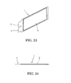
- A flat-rechargeable battery 1 formed in a plate shape as shown in
Fig. 23 and Fig. 24 is used in many technical fields, and this flat-rechargeable battery 1 has a pair ofelectrode terminals flat case 3. - Similarly to conventional rechargeable batteries, the flat-rechargeable batteries 1 also undergo a charge/discharge test for quality inspection several times after produced in a factory, and thereafter acceptable products are half-charged to be shipped as products.
-
Fig. 25 shows a charge/discharge testing device for flat-rechargeable batteries disclosed in Japanese Unexamined Patent Application Publication No.2000-58135 discharge rack 13 provided with a group of vertically hung clip-type coupling terminals 11 coupled withelectrode terminals contact support 17 disposed to face the group of the coupling terminals 11 and supporting a group ofcontacts 15 coming into contact or separating from the coupling terminals 11, a support reciprocatingmechanism 19 reciprocating the contact support 1 7 in a predetermined direction to make the corresponding coupling terminals 11 andcontacts 15 come into contact with or separate from each other, and a charge/discharge power source 21 coupled with the group of thecontacts 15, and the charge/discharge testing device 9 is capable of conducting a charge/discharge test of a large number of the flat-rechargeable batteries 1 at a time. - Further, Japanese Unexamined Patent Application Publication No.
2004-319334 - In this manner, the charge/discharge testing device 9 is capable of conducting the charge/discharge test of the many flat-rechargeable batteries 1 at a time, but it took a lot of trouble to couple the flat-rechargeable batteries 1 (
electrode terminals 5, 7) with the group of the many clip-type coupling terminals 11. - In addition, there have been pointed out drawbacks that a place for the charge/discharge test is limited and the whole device becomes large since the charge/
discharge rack 13 including the group of the coupling terminals 11 are integrally assembled in the charge/discharge testing device 9. - Further, though capable of conducting the charge/discharge test of the many flat-rechargeable batteries at a time, the conventional example disclosed in Japanese Unexamined Patent Application Publication No.
2004-319334 - On the other hand, however, at the time of the charge/discharge test, without the structure fixing the flat-rechargeable batteries such as the battery container, positions of electrodes of the flat-rechargeable batteries become irregular, which is likely to result in incapability of accurate chucking.
- The present application was invented in consideration of the above-described circumstances and has a proposition to provide a chuck mechanism of a charge/discharge testing device for flat-rechargeable batteries which makes it possible to lighten the aforesaid conventionally needed troublesome works, that is, the work of coupling the flat-rechargeable batteries with the group of the clip-type coupling terminals and the work of storing and arranging the many flat-rechargeable batteries in the battery container and which is capable of surely chucking the flat-rechargeable batteries (electrodes).
- To attain the above proposition, a chuck mechanism of a charge/discharge testing device for flat-rechargeable batteries according to one embodiment of the present application includes a first guide couplable with a battery storage retaining a plurality of flat-rechargeable batteries arranged in parallel, and a plurality of chuck units continuously joined with the first guide and resiliently arranged in parallel, wherein the chuck units each have a second guide resiliently positioning each of the chuck units with a predetermined number of corresponding flat-rechargeable batteries in the battery storage.
- Another embodiment of the present application is the chuck mechanism, wherein the second guide is made up of a pair of two positioning pins fastening a positioner that is formed in the battery storage corresponding to each of the chuck units, and each pair of the positioning pins becomes shorter in order from both ends toward a center of the plurality of chuck units arranged in parallel.
- Still another embodiment of the present application is the chuck mechanism, wherein the chuck units include a roller-retaining member which is movable in a front and rear direction of a support base when a driver mounted on the support base is driven and in which a plurality of divided roller-retaining members are movably arranged in parallel via a shaft extending in a left and right direction of the support base, the divided roller-retaining members arranging in parallel a plurality of pairs of rollers vertically on each front surface of the divided roller-retaining members, and a chuck-retaining member in which a plurality of divided chuck-retaining members each making one unit with each of the divided roller-retaining members are resiliently and movably arranged in parallel via the shaft extending in the left and right direction of the support base, wherein the divided chuck-retaining members each have a plurality of chuck members each made up of a pair of two strip-formed metal plates inserted through a gap between each of the pairs of rollers, with front end sides of the metal plates fanning out in a V shape in a plane view and with rear end sides of the metal plates coupled with electric wires of the charge/discharge testing device, and wherein the second guide is provided in each of the divided chuck-retaining members.
- Yet another embodiment of the present application is the chuck mechanism, wherein an oxide film exfoliating/fastening member having a large number of projections on a fastening surface of the oxide film exfoliating/fastening member is fixed on front ends of a pair of two chuck members, and yet another embodiment of the present application is the chuck mechanism according to the above embodiment, wherein the oxide film exfoliating/fastening member has a guide inclining inward from the front end sides of the chuck members toward the fastening surface.
- Yet another embodiment of the present application is the chuck mechanism, wherein slits are formed in a front and rear direction in the front ends of the chuck members, and the oxide film exfoliating/fastening member is fixed on each front end of the chuck members demarcated by the slits.
- According the aforementioned embodiments, it is possible to chuck electrode terminals by the chuck units accurately and favorably while lightening troublesome works of storing and fixing a large number of flat-rechargeable batteries in a predetermined container or the like prior to a charge/discharge test as has been required conventionally.
- That is, the present application is structured such that, in the battery storage side, it is only necessary to fasten the flat-rechargeable batteries which are arranged in parallel, and when the battery storage is thereafter moved close to the chuck mechanism, the first guide adjusts a chuck width of the chuck mechanism according to a battery storage width of the battery storage, and thereafter the chuck units resiliently and continuously joined with the first guide are positioned with the flat-rechargeable batteries by the second guide automatically and resiliently in sequence, which as a result has an advantage of improving chuck accuracy while reducing a work load.
-
-
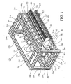
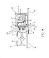
Fig. 1 is a front perspective view of a chuck mechanism. -
Fig. 2 is a rear perspective view of the chuck mechanism. -
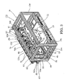
Fig. 3 is a rear perspective view of the chuck mechanism. -
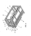
Fig. 4 is a rear perspective view of the chuck mechanism. -
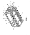
Fig. 5 is a rear perspective view of the chuck mechanism. -
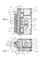
Fig. 6 is a plane view of the chuck mechanism. -
Fig. 7 is a side view of the chuck mechanism. -
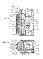
Fig. 8 is a plane view of the chuck mechanism in a state where chuck members are closed by rollers. -
Fig. 9 is a side view of the chuck mechanism in the state where the chuck members are closed by the rollers. -
Fig. 10 is an enlarged perspective view of an essential part of the chuck mechanism. -
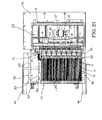
Fig. 11 is a front perspective view of a divided roller-retaining member and a divided chuck-retaining member. -
Fig. 12 is a rear perspective view of the divided roller-retaining member and the divided chuck-retaining member. -
Figs. 13A , B, C are a plane view, a front view, and a bottom view of an exfoliating/fastening member, respectively. -
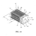
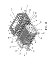
Fig. 14 is a front perspective view of a magazine. -
Fig. 15 is an enlarged perspective view of an essential part of the chuck mechanism and the magazine disposed to face the chuck mechanism. -
Fig. 16 is a perspective view of the chuck mechanism and the magazine disposed to face the chuck mechanism. -
Fig. 1 7 is a plane view of the chuck mechanism and the magazine disposed to face the chuck mechanism. -
Fig. 18 is a side view of the chuck mechanism and the magazine disposed to face the chuck mechanism. -
Fig. 19 is a plane view of the chuck mechanism and the magazine disposed to face the chuck mechanism. -
Fig. 20 is a side view of the chuck mechanism and the magazine disposed to face the chuck mechanism. -
Fig. 21 is a plane view of the chuck mechanism whose chuck members are fastening electrode terminals, and the magazine. -
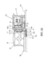
Fig. 22 is a side view of the chuck mechanism whose chuck members are fastening the electrode terminals, and the magazine. -
Fig. 23 is a perspective view of a flat-rechargeable battery. -
Fig. 24 is a plane view of the flat-rechargeable battery. -
Fig. 25 is a front view of a charge/discharge testing device disclosed in Patent Document 1. - Hereinafter, an embodiment of the present invention will be described in detail based on the drawings.
-
Fig. 1 to Fig. 12 show a chuck mechanism of a charge/discharge testing device for flat-rechargeable batteries according to an embodiment of the present invention, and inFig. 1 to Fig. 5 , 31 denotes a support base which is a rectangular parallelepiped frame made up of a plurality ofsupport posts 31 a to 31 w disposed on front, back, right, and left sides, and as shown inFig. 1 andFig. 2 , amounting plate 33 in a rectangular shape in a plane view is mounted between thesupport post 31 w, which is bridged between the left and right support posts 31o, 31 p, and the support post 31 q, which is bridged between thesupport posts mounting plate 33, an air cylinder (driver) 37 whosepiston rod 35 is expandable/contractible in a front and rear direction of thesupport base 31 is mounted as shown inFig. 6 to Fig. 9 . - As shown in
Fig. 6 to Fig. 9 , on a front end of thepiston rod 35, a roller-retainingmember 41 is mounted via asupport frame 39, and further, a chuck-retainingmember 43 facing the roller-retainingmember 41 is mounted to be movable in a right and left direction of thesupport base 31 along oneshaft 45 bridged between the left andright support posts 31 k, 31l of thesupport base 31, and the roller-retainingmember 41 and the chuck-retainingmember 43 form chuck units in this embodiment. - Specifically, as shown in
Fig. 2 ,Fig. 6 , andFig. 8 , through acasing 37a of theair cylinder 37,columnar guide members 47 are inserted along thepiston rod 35, one on the right side and the other one on the left side of thepiston rod 35. - A
coupler plate 51 in a rectangular shape in a front view made of one plate member and having a risingwall 49 for reinforcement formed along its peripheral edge is fixed to front ends of the bothguide members 47 and thepiston rod 35, so as to face a front surface of thesupport base 31 and so as to extend long in a lateral direction. - Six
support posts coupler plate 51 at predetermined intervals, and onesupport post 55 and onesupport post 57 are fixed respectively to upper sides and lower sides of thesupport posts support base 31. As shown inFig. 2 ,Fig. 3 ,Fig 7 , andFig. 9 , onesupport plate 59 and onesupport plate 61 both in a C shape in a side view are fixed between left end portions of the upper andlower support posts support posts base portions 59a, 61 a of thesupport plates support frame 39. - As shown in
Fig. 1 to Fig. 6 andFig. 10 , oneshaft 63 is bridged on front end sides ofupper arms base portions 59a, 61 a of thesupport plates shaft 65 is bridged in parallel to theshaft 63 between front end sides oflower arms base portions 59a, 61 a. Between the two upper andlower shafts member 41 in which a plurality of divided roller-retainingmembers 67 are arranged in parallel is formed. -
Fig. 11 andFig. 12 show the divided roller-retainingmember 67 and a divided chuck-retainingmember 69 making a unit with the divided roller-retainingmember 67. The plural divided roller-retainingmembers 67 are arranged in parallel between theshafts member 41 as previously described, and the plural divided chuck-retainingmembers 69 are arranged in parallel along theshaft 45 to form the chuck-retainingmember 43. - In
Fig. 11 andFig. 12 , 71 denotes a roller mounting plate being one plate, which has, on its upper and lower portions, mountingflanges walls 77 for reinforcement. As shown inFig. 10 , retainingmembers 79 in a block shape through which theshaft 63 is inserted are fixed to theupper mounting flanges 73 and retainingmembers 81 in a block shape through which theshaft 65 is inserted are fixed to thelower mounting flanges 75, and all the divided roller-retainingmembers 67 are movably mounted between the upper andlower shafts members 79. 81. - Further, as shown in
Fig. 11 , theroller mounting plate 71 has, in upper and lower portions of its front surface,insertion holes chuck members long hole 91 is opened in a lateral direction between the bothinsertion holes roller mounting brackets upper insertion hole 87, and four pairs ofcolumnar rollers 97 are rotatably mounted between the bothroller mounting brackets - As shown in
Fig. 11 , the upperroller mounting bracket 93 includes: a firstroller mounting bracket 93a with a substantially L-shaped cross section in whose front ends a plurality of roller insertion holes 99 having therollers 97 inserted therethrough are opened at equal intervals; and a secondroller mounting bracket 93b with a substantially L-shaped cross section disposed above the firstroller mounting bracket 93a, with a small gap therebetween, and support holes 103 supportingshafts 101 of therollers 97 are provided in a front end portion of the secondroller mounting bracket 93b in correspondence to the roller insertion holes 99. - In a front end portion of the other
roller mounting bracket 95, support holes 105 supporting the shafts of therollers 97 are formed in correspondence to the support holes 103, and the four pairs ofrollers 97 are rotatably mounted between theroller mounting brackets - A similar
roller mounting bracket 93 is mounted upside down on a lower side of thelower insertion hole 89, and a similarroller mounting bracket 95 is mounted upside down on an upper side of theinsertion hole 89, and a four pairs ofrollers 97 are rotatably mounted between the bothroller mounting brackets - The divided roller-retaining
member 67 is thus structured, and the plural divided roller-retainingmembers 67 are movably mounted between theshafts member 41 movable in the front and rear direction of thesupport base 31 by theair cylinder 37 being driven. - Next, the chuck-retaining
member 43 will be described. As shown inFig. 1 to Fig. 10 ,support brackets support base 31 respectively, and thesingle shaft 45 is bridged between the bothsupport brackets shafts Fig. 11 andFig. 12 , theshaft 45 is inserted through retainingmembers 111 of the divided chuck-retainingmembers 69. - As previously described, the divided chuck-retaining
member 69 and the divided roller-retainingmember 67 are formed as a unit to make a pair, and the plural divided chuck-retainingmembers 69 are arranged in parallel along theshaft 45 to form the chuck-retainingmember 43. - In
Fig. 11 andFig. 12 , 113 denotes a thick chuck mounting plate disposed along theroller mounting plate 71, and at a center of its rear surface side, the retainingmember 111 in the block shape through which theshaft 45 is inserted is mounted. On a front surface of thechuck mounting plate 113, the fourchuck members 83 disposed in parallel in the lateral direction and the fourchuck members 85 disposed in parallel in the lateral direction, each corresponding to the aforesaid each pair of therollers 97, are disposed in two tiers. - As is shown in the drawings, the
chuck members metal plates metal plates chuck mounting plate 113. The rear ends of themetal plates 115 projecting from a rear surface of thechuck mounting plate 113 are bent in an L shape along the rear surface of thechuck mounting plate 113 to be screw-fixed to the rear surface. - Similarly, the rear ends of the
other metal plates 117 projecting from the rear surface of thechuck mounting plate 113 are bent in an L shape along the rear surface of thechuck mounting plate 113 to be screw-fixed to the rear surface, and as shown inFig. 12 , the rear ends of themetal plates chuck mounting plate 113. Electric wires from the charge/discharge testing device can be coupled with the rear ends of themetal plates chuck mounting plate 113. - As shown in
Fig. 11 , the aforesaid pairs ofrollers 97 are each disposed so as to correspond to each of thechuck members 83, 85 (metal plates 115, 117) projecting to a front side of thechuck mounting plate 113, and each pair of themetal plates rollers 97. - As is shown in the drawings, front end sides of the
metal plates rollers 97 fan out in a substantially V shape in a plane view, with their leading ends being bent slightly inward, and as will be described later, when the roller-retainingmember 41 moves forward by theair cylinder 37 being driven, each pair of themetal plates 115, 117 (chuckmember 83, 85) fanning out in a substantially V shape in a plane view is closed by each pair of therollers 97. - Further, slits 119 are formed in the front and rear direction in the front ends of the
metal plates slits 119 being formed in each of themetal plates upper chuck member 83 and twoslits 119 being formed in each of themetal plates lower chuck member 85. - As shown in
Fig. 11 , a pair of oxide film exfoliating/fastening members (hereinafter, referred to as "exfoliating/fastening members) 121 are caulk-fixed to tip sides demarcated by theslits 119 in each pair of themetal plates - Specifically, as shown in
Fig. 10 , mountingholes 123 to which the exfoliating/fastening members 121 are caulk-fixed are provided in the front end sides demarcated by theslits 119 in themetal plates Figs. 13(a) to (c) , the exfoliating/fastening members 121 each have aleg portion 121 a caulk-fixed to the mountinghole 123 and ahead portion 121 b in a thick disk shape in a plane view integrally formed with theleg portion 121 a. Six spike pins 127 are projectingly provided on afastening surface 125 being a top portion of thehead portion 121 b, and as will be described later, when themetal plates rollers 97 while anelectrode terminal metal plates spike pins 127 of each of the exfoliating/fastening members 121 on one side and the sixspike pins 127 of each of the exfoliating/fastening member 121 on the other side come into pressure contact with front and rear surfaces of theelectrode terminal electrode terminal - Further, as shown in
Fig. 11 andFigs. 13(a) to (c) , guides 129 inclining inward from the front end sides of thechuck members head portions 121 b, and theguide members 129 guide the displacedelectrode terminals - As previously described, the plural divided chuck-retaining
members 69 are arranged in parallel along theshaft 45 to form the chuck-retainingmember 43, and as shown inFig. 1 ,Fig. 6 , andFig. 10 , on the support post 31l side of thesupport base 31, one width-deciding/fastening member (first guide) 135 fastening abattery pressing plate 133 of a later-described magazine (battery storage) 131 is movably mounted on theshaft 45. - As is shown in the drawings, the width-deciding/
fastening member 135 includes: a base 137 in a rectangular shape in a plane view that is equal in thickness to thechuck mounting plate 113; and afastening arm 139 in a U-shape in a plane view mounted on a front surface of thebase 137, and the retainingmember 111 is mounted on a rear surface side of thebase 137. Further, in lower portions of left and right side surfaces of thebase 137, bottomed shaft insertion holes 141 each having a step therein are provided, and as shown inFig. 10 ,positioning shafts 143 are inserted in the both shaft insertion holes 141 one per each, and further, acoil spring 145 is wound around an outer periphery of each of thepositioning shafts 143. - The
positioning shaft 143 inserted in theshaft insertion hole 141 on the support post 31l side is inserted and supported in a spring insertion hole (not shown) of asupport bracket 109 mounted on thesupport post 311, and one end side of thecoil spring 145 is inserted and retained in the spring insertion hole. - The not-shown positioning shaft inserted in the shaft insertion hole (not shown) opposite the support post 31l and its coil spring are inserted and supported in a
spring insertion hole 147 provided in thechuck mounting plate 113 adjacent thereto. - Specifically, as shown in
Fig. 11 , aspring mounting hole 149 in which one end side of thecoil spring 145 is inserted and retained is formed in a left side surface of thechuck mounting plate 113, and thereunder, a positioning pin (rotation stopping pin) 151 is projectingly provided. - As shown in
Fig. 12 , in a right side surface of thechuck mounting plate 113, aspring insertion hole 147 in which thecoil spring 145 on the adjacentchuck mounting plate 113 side is insertable and a positioning pin insertion hole 1 53 in which thepositioning pin 151 is insertable are formed. - Further, as shown in
Fig. 7 , on upper and lower sides of thesupport bracket 107 mounted on thesupport post 31 k, receiving parts 1 55, 1 57 retaining thecoil spring 145 and thepositioning pin 151 of thechuck mounting plate 113 3 adjacent to thesupport post 31 k are formed, so that the divided chuck-retainingmembers 69 and the width positioning/fastening member 135 which are arranged along theshaft 45 between the left and right support posts 31 k, 31l are continuously provided via the coil springs 145 and the positioning pins 151, and are arranged at equal intervals between thesupports 31 k, 31l owing to spring forces of the coil springs 145. -
Fig. 14 shows themagazine 131 in which a large number of the flat-rechargeable batteries 1 as targets of the charge/discharge test are stored, and as shown in the drawing, themagazine 131 includes: a pair ofside plates partition walls 165 arranged between the bothside plates battery pressing plate 133 disposed on one end side (plate 163 side) of a group of thepartition walls 165 so as to face the width positioning/fastening member 135; and four guide stays 167 passing through four corners of each of thepartition walls 165 and thebattery pressing plate 133 and bridged between four corners of theside plate 161 and four corners of theside plate 163, and thepartition walls 165 and thebattery pressing plate 133 are movable along the guide stays 167. - As shown in
Fig. 14 andFig. 17 , between theside plate 161 and thebattery pressing plate 133, thepartition walls 165 demarcate and form storage chambers each storing one flat-rechargeable battery 1 in a vertical direction, with theelectrode terminals members partition walls 165 is equal to the number of the upper andlower chuck members - On a side surface of the
battery pressing plate 133, a not-shown screwing part is formed, and one end side of oneadjustment screw 169 inserted through theside plate 163 is screwed to the screwing part. When theadjustment screw 169 is loosened, thepartition walls 165 become movable along the guide stays 167 between theside plate 161 and thebattery pressing plate 133, and when theadjustment screw 169 is fastened after the flat-rechargeable batteries 1 are stored in the storage chambers, one for each, thebattery pressing plate 133 presses and fixes thepartition walls 165, so that a battery storage width L of themagazine 131 is decided according to the number of thepartition walls 165. - Further, as shown in
Fig. 14 andFig. 19 , on thebattery pressing plate 133, a tapered fastened piece (positioner) 1 71 projecting toward thefastening arm 139 is provided, and as will be described later, when themagazine 131 is pulled toward thechuck mechanism 173 of this embodiment, thefastening arm 139 first fastens the fastenedpiece 171 as shown inFig. 19 . - Therefore, the positions of the divided chuck-retaining
members 69 and the width-deciding/fastening member 135 which are arranged along theshaft 45 between the left and right support posts 31 k, 31l at equal intervals owing to the spring forces of the coil springs 145 as previously described are newly adjusted so that they are arranged at equal intervals within a dimension of the battery storage width L owing to the spring forces. At this time, the positioning pins 151 provided on the respective divided chuck-retainingmembers 69 are inserted in the pin insertion holes 153 of the adjacent divided chuck-retainingmembers 69 to position the divided chuck-retainingmembers 69, which prevent the rotation of the chuck-retainingmembers 43 around theshaft 45. - Further, as shown in
Fig. 14 andFig. 15 , at the centers of thepartition walls 165, second fastened pieces (positioners) 1 75 projecting toward thechuck mechanism 173 are provided, and the fastenedpieces 175 are tapered and are located on a more back side than the fastened piece 1 71. - As shown in
Fig. 11 , in each of the divided chuck-retainingmembers 69, two positioning pins (second guides) 177 inserted through thelong hole 91 of theroller mounting plate 71 are provided so as to project forward, and when the fastening arm 1 39 fastens the fastenedpiece 171 as is previously described and themagazine 131 is thereafter further pulled toward thechuck mechanism 173, the twopositioning pins 177 fasten the single fastened piece 1 75 facing them, from left and right. - Incidentally, as shown in
Fig. 1 5 , pairs of the two positioning pins 1 77 are formed to become shorter in order from those of the left and right divided chuck-retainingmembers 69 to those of the center divided chuck-retainingmember 69, so that all the positioning pins 1 77 do not fasten the fastened pieces 1 75 at a time but the positioning pins 177 sequentially fasten the fastenedpieces 175 in order from the left and right side positioning pins 177 to the center positioning pins 177. - The chuck mechanism 1 73 according to this embodiment and the
magazine 131 are structured as above, and to conduct the charge/discharge test of the flat-rechargeable batteries 1 by using thechuck mechanism 173, thechuck mechanism 173 is first placed on a predetermined mounting table 1 79 as shown inFig. 16 . - As shown in
Fig. 15 andFig. 16 , in front of the mounting table 179, aguide mechanism 185 including twoguide rails 181 and a movable table 183 movably mounted on the twoguide rails 181 is installed. A piston rod of a not-shown air cylinder mounted on a rear surface side of the mounting table 179 is coupled with the movable table 183, so that the mounting table 179 is movable in the front and rear direction along theguide rails 181 when the air cylinder is driven. - Next, the
magazine 131 inFig. 14 in whose storage chambers the plural flat-rechargeable batteries 1 are stored is carried onto the movable table 183 by a stacker crane and the base 1 59 is fixed to the movable table 183. At this time, in themagazine 131, theadjustment screw 169 has already been fastened and the predetermined battery storage width L has been set. - Consequently, as shown in
Fig. 15 to Fig. 18 , themagazine 131 is disposed on the movable table 183 so as to face the chuck mechanism 1 73, and theelectrode terminals chuck members - The chuck mechanism 1 73 and the
magazine 131 are pre-designed so that at this time, thefastening arm 139 of the width-deciding/fastening member 135 faces thebattery pressing plate 133. Further, the number of the storage chambers demarcated by thepartition walls 165 is equal to the number of thechuck members chuck members - Thereafter, when the air cylinder on the rear surface side of the mounting table 179 is driven to contract the piston rod coupled with the movable table 183, the
fastening arm 139 first fastens the fastenedpiece 171 of thebattery pressing plate 133 while themagazine 131 moves along theguide rails 181 toward thechuck mechanism 173. - Then, the adjustment is automatically made anew so that the divided chuck-retaining
members 69 arranged between the left and right support posts 31 k, 31l at equal intervals owing to the spring forces of the coil springs 145 are arranged at equal intervals between thewidth fastening member 135 and thesupport 31 k within the dimension of the battery storage width L owing to the spring forces, and at this time, the positioning pins 151 are inserted in the pin insertion holes 153 of the adjacent divided chuck-retainingmembers 69 to position the divided chuck-retainingmembers 69, so that the rotation of the chuck-retainingmember 43 around theshaft 45 is constantly prevented. - In accordance with further movement of the
magazine 131, while thepositioning pins 177 projectingly provided on the right and left divided chuck-retainingmembers 69 with longer length fasten the fastenedpieces 175 first, the divided chuck-retainingmembers 69 therebetween are arranged at equal intervals owing to the spring forces of the coil springs 145, and then their intervals are further equally adjusted sequentially. Then, as shown inFig. 19 andFig. 20 , when themagazine 131 moves by a predetermined distance and the air cylinder stops, theelectrode terminals metal plates upper chuck member 83 and the twometal plates lower chuck members 85 respectively. - Incidentally, since the exfoliating/
fastening members 121 fixed on themetal plates guides 129 inclining inward from the tip end sides of thechuck members such guide members 129 guide the displacedelectrode terminals - Thereafter, when the electric wires of the charge/discharge testing device are coupled with the rear ends of the
metal plates chuck mounting plates 113 of the divided chuck-retainingmembers 69 and theair cylinder 37 is driven, thepiston rod 35 extends forward, so that the roller-retaining member 41 (the divided roller-retaining members 67) mounted on thepiston rod 35 moves forward. Then, when the roller-retainingmember 41 thus moves, themetal plates chuck members rollers 97 as shown inFig. 21 andFig. 22 , so that the fastening surfaces 125 of the exfoliating/fastening members 121 fixed on the front end sides of themetal plates lower electrode terminals - In this embodiment, the
plural slits 119 are provided in the front and rear direction in the front end of each of themetal plates metal plates metal plates fastening members 121 of themetal plates electrode terminals electrode terminals - Thereafter, electricity is supplied through the electric wires of the charge/discharge testing device coupled with the rear end sides of the
chuck members 83, 85 (themetal plates 115, 117), and the charge/discharge test of the flat-rechargeable batteries 1 each fastened by thechuck members - Then, after the end of the test, when the
piston rod 35 of theair cylinder 37 is contracted backward and the roller-retainingmember 41 is moved backward, themetal plates chuck members rollers 97 fan out again as shown inFig. 19 . - Thus using the
chuck mechanism 173 according to this embodiment at the time of the charge/discharge test of the flat-rechargeable batteries 1 naturally makes it possible to conduct the charge discharge test of a large number of the flat-rechargeable batteries 1 at a time, and also makes it possible to accurately and favorably chuck theelectrode terminals chuck members - That is, as described above, in this embodiment, on the
magazine 131 side, it is only necessary to fasten the flat-rechargeable batteries 1 in the storage chambers, and thereafter, when themagazine 131 is moved close to thechuck mechanism 173, thefastening arm 139 first fastens the fastenedpiece 171 of thebattery pressing plate 133, so that the chuck width is adjusted, and thereafter, while the positioning pins 1 77 with the longer length projectingly provided on the left and right divided chuck-retainingmembers 69 first fasten the fastenedpieces 175, the divided chuck-retainingmembers 69 therebetween are arranged evenly by the spring forces of the coil springs 145 so that their intervals are equally adjusted in sequence, and as a result, chuck accuracy is improved while a work load is lightened. - In addition, it is possible to quickly conduct the charge/discharge test only by carrying the
magazine 131 storing a large number of the flat-rechargeable batteries 1 to the front surface of thechuck mechanism 173, and therefore, a place for the charge/discharge test is not limited. - Further, the fanning-out
metal plates chuck members rollers 97, which enables a smooth opening/closing operation of themetal plates plural slits 119 are provided in the front and rear direction in the front ends of themetal plates metal plates electrode terminals guide members 129 of the exfoliating/fastening members 121. This structure has advantages that, even if themetal plates electrode terminals metal plates 115, 117 (exfoliating/fastening members 121) and the oxide films on the surfaces of theelectrode terminals - Further, the plural divided roller-retaining
members 67 are arranged in parallel in the lateral direction to form the roller-retainingmember 41 and the plural divided chuck-retainingmembers 69 are arranged in parallel in the lateral direction to form the chuck-retainingmember 43, which has an advantage of facilitating the change of individual components and maintenance. - Incidentally, in the above-described embodiment, the pairs of two positioning
pins 177 being the second guides are formed to become shorter in order from those of the left and right divided chuck-retainingmembers 69 toward those of the center divided chuck-retainingmember 69, but the pairs of two positioningpins 177 may be formed to become shorter in order from those on the side of the width-deciding/fastening member 135 being the first guide toward those on theother support 31 k side, and such an embodiment is capable of attaining the desired proposition similarly to the above-described embodiment. - Further, in the above-described embodiment, as the driver moving the roller-retaining
member 41 back and forth, theair cylinder 37 is used, but the driver is not limited to the air cylinder, and a motor of any other actuator may be used as the driver. - The many features and advantages of the embodiments are apparent from the detailed specification and, thus, it is intended by the appended claims to cover all such features and advantages of the embodiments that fall within the true spirit and scope thereof. Further, since numerous modifications and changes will readily occur to those skilled in the art, it is not desired to limit the inventive embodiments to the exact construction and operation illustrated and described, and accordingly all suitable modifications and equivalents may be resorted to, falling within the scope thereof.
Claims (6)
- A chuck mechanism of a charge/discharge testing device for flat-rechargeable batteries comprising:a first guide couplable with a battery storage retaining a plurality of flat-rechargeable batteries arranged in parallel; anda plurality of chuck units continuously joined with the first guide and resiliently arranged in parallel, whereinthe chuck units each have a second guide resiliently positioning each of the chuck units with a predetermined number of corresponding flat-rechargeable batteries in the battery storage.
- The chuck mechanism of the charge/discharge testing device for flat-rechargeable batteries according to claim 1, wherein:the second guide is made up of a pair of two positioning pins fastening a positioner that is formed in the battery storage corresponding to each of the chuck units; andeach pair of the positioning pins becomes shorter in order from both ends toward a center of the plurality of chuck units arranged in parallel.
- The chuck mechanism of the charge/discharge testing device for flat-rechargeable batteries according to claim 1 or 2, wherein:the chuck units include
a roller-retaining member which is movable in a front and rear direction of a support base when a driver mounted on the support base is driven and in which a plurality of divided roller-retaining members are movably arranged in parallel via a shaft extending in a left and right direction of the support base, the divided roller-retaining members arranging in parallel a plurality of pairs of rollers vertically on each front surface of the divided roller-retaining members, and
a chuck-retaining member in which a plurality of divided chuck-retaining members each making one unit with each of the divided roller-retaining members are resiliently and movably arranged in parallel via the shaft extending in the left and right direction of the support base;the divided chuck-retaining members each have a plurality of chuck members each made up of a pair of two strip-formed metal plates inserted through a gap between each of the pairs of rollers, with front end sides of the metal plates fanning out in a V shape in a plane view and with rear end sides of the metal plates coupled with electric wires of the charge/discharge testing device; andthe second guide is provided in each of the divided chuck-retaining members. - The chuck mechanism of the charge/discharge testing device for flat-rechargeable batteries according to claim 3, wherein
an oxide film exfoliating/fastening member having a large number of projections on a fastening surface of the oxide film exfoliating/fastening member is fixed on front ends of a pair of two chuck members. - The chuck mechanism of the charge/discharge testing device for flat-rechargeable batteries according to claim 4, wherein
the oxide film exfoliating/fastening member has a guide inclining inward from the front end sides of the chuck members toward the fastening surface. - The chuck mechanism of the charge/discharge testing device for flat-rechargeable batteries according to claim 4 or 5, wherein
slits are formed in a front and rear direction in the front ends of the chuck members, and the oxide film exfoliating/fastening member is fixed on each front end of the chuck members demarcated by the slits.
Applications Claiming Priority (1)
| Application Number | Priority Date | Filing Date | Title |
|---|---|---|---|
| JP2010138189A JP5498273B2 (en) | 2010-06-17 | 2010-06-17 | Chuck mechanism of charge / discharge test equipment for thin secondary batteries |
Publications (3)
| Publication Number | Publication Date |
|---|---|
| EP2398089A2 true EP2398089A2 (en) | 2011-12-21 |
| EP2398089A3 EP2398089A3 (en) | 2013-04-17 |
| EP2398089B1 EP2398089B1 (en) | 2016-10-05 |
Family
ID=44503466
Family Applications (1)
| Application Number | Title | Priority Date | Filing Date |
|---|---|---|---|
| EP11004944.2A Active EP2398089B1 (en) | 2010-06-17 | 2011-06-16 | Chuck mechanism of charge/discharge testing device for flat-rechargeable batteries |
Country Status (4)
| Country | Link |
|---|---|
| US (1) | US8618804B2 (en) |
| EP (1) | EP2398089B1 (en) |
| JP (1) | JP5498273B2 (en) |
| CN (1) | CN102290615B (en) |
Cited By (3)
| Publication number | Priority date | Publication date | Assignee | Title |
|---|---|---|---|---|
| KR20150134396A (en) * | 2013-05-01 | 2015-12-01 | 닛산 지도우샤 가부시키가이샤 | Charging and discharging inspection device and charging and discharging inspection method for thin secondary battery |
| US9520727B2 (en) | 2013-08-29 | 2016-12-13 | Lg Chem, Ltd. | Gripper assembly for battery charging and discharging |
| EP4152470A1 (en) * | 2021-09-17 | 2023-03-22 | Wonik Pne Co., Ltd. | Jig for battery charging and discharging test |
Families Citing this family (25)
| Publication number | Priority date | Publication date | Assignee | Title |
|---|---|---|---|---|
| JP5804975B2 (en) * | 2012-02-28 | 2015-11-04 | 富士通テレコムネットワークス株式会社 | Secondary battery charging / discharging device |
| JP5834359B2 (en) * | 2012-02-28 | 2015-12-16 | 株式会社ダイフク | Goods storage equipment |
| JP5870405B2 (en) * | 2012-02-28 | 2016-03-01 | 株式会社ダイフク | Goods transport equipment |
| JP5838520B2 (en) * | 2012-02-28 | 2016-01-06 | 株式会社ダイフク | Goods transport equipment |
| CN102790299B (en) * | 2012-07-27 | 2014-10-15 | 东华大学 | Flatbed electrode fixture applicable to lithium battery formation automatic production line |
| JP2014102883A (en) * | 2012-11-16 | 2014-06-05 | Fujitsu Telecom Networks Ltd | Chuck device |
| KR101509206B1 (en) | 2013-07-23 | 2015-04-10 | (주)이티에이치 | Secondary battery charge and discharge jig with improved grippre exchange structure |
| JP6233105B2 (en) * | 2014-03-07 | 2017-11-22 | 株式会社富士通テレコムネットワークス福島 | Energized chucking durability test equipment |
| JP6323131B2 (en) * | 2014-04-09 | 2018-05-16 | 日産自動車株式会社 | Pressure device for film-clad battery |
| JP6292023B2 (en) * | 2014-05-20 | 2018-03-14 | 日産自動車株式会社 | Polygon member alignment device |
| KR101937995B1 (en) * | 2015-06-04 | 2019-01-11 | 주식회사 엘지화학 | Test Device for function of Battery Pack |
| JP6540368B2 (en) * | 2015-08-21 | 2019-07-10 | 日産自動車株式会社 | Battery cell storage device |
| CN105449287B (en) * | 2015-10-23 | 2018-02-13 | 万向一二三股份公司 | A kind of formation of Li-ion batteries frock |
| JP6759571B2 (en) * | 2015-12-15 | 2020-09-23 | 株式会社豊田自動織機 | Battery pack |
| CN105826486B (en) * | 2016-04-29 | 2018-08-17 | 无锡港盛重型装备有限公司 | A kind of protective device of accumulator |
| DE102017203957A1 (en) | 2017-03-10 | 2018-09-13 | Thyssenkrupp Ag | Formation plant and method for delivery to a formation plant |
| TWI629816B (en) * | 2017-07-21 | 2018-07-11 | 廣運機械工程股份有限公司 | Charging-and-discharging dock for secondary battery |
| CN109301305B (en) * | 2018-10-29 | 2020-04-24 | 惠安佳瑞汽车销售服务有限公司 | A loading equipment for new energy automobile battery equipment |
| CN111208321B (en) * | 2018-11-02 | 2021-11-23 | 沈阳新松机器人自动化股份有限公司 | Compatible type laminate polymer battery adds electric testing arrangement |
| CN111755760B (en) * | 2019-03-28 | 2021-08-24 | 浙江吉智新能源汽车科技有限公司 | A battery pack verification device |
| JP7159965B2 (en) | 2019-04-22 | 2022-10-25 | トヨタ自動車株式会社 | SECONDARY BATTERY MODULE AND SECONDARY BATTERY MODULE MANUFACTURING METHOD |
| EP4184653A4 (en) * | 2020-08-28 | 2024-08-14 | Hirata Corporation | TESTING AND MANUFACTURING PROCEDURES |
| TWI780522B (en) * | 2020-11-25 | 2022-10-11 | 致茂電子股份有限公司 | Battery fixture with variable pitch and battery cell formation apparatus having the same |
| CN115951243B (en) * | 2022-12-23 | 2023-08-22 | 广州市虎头电池集团股份有限公司 | Alkaline battery batch testing device |
| EP4621894A1 (en) * | 2024-03-20 | 2025-09-24 | MacroCaps ApS | Energy storage array for energy storage devices |
Citations (2)
| Publication number | Priority date | Publication date | Assignee | Title |
|---|---|---|---|---|
| JP2000058135A (en) | 1998-08-10 | 2000-02-25 | Toshiba Battery Co Ltd | Charging and discharging device for thin type secondary battery |
| JP2004319334A (en) | 2003-04-17 | 2004-11-11 | Nittetsu Elex Co Ltd | Charging/discharging and inspection system of flat battery |
Family Cites Families (11)
| Publication number | Priority date | Publication date | Assignee | Title |
|---|---|---|---|---|
| DE3207545C1 (en) * | 1982-03-03 | 1983-08-25 | Deta-Akkumulatorenwerk Gmbh, 3422 Bad Lauterberg | Test equipment for testing an accumulator |
| JPH11271409A (en) * | 1998-03-23 | 1999-10-08 | Sony Corp | Battery tray and battery test method |
| KR100326898B1 (en) * | 2000-07-12 | 2002-03-06 | 신동희 | Charge and discharge system for battery |
| JP2002134176A (en) | 2000-10-30 | 2002-05-10 | Mikuni Kogyo:Kk | Charge / discharge / inspection mechanism for lithium polymer batteries |
| JP2002298929A (en) * | 2001-03-30 | 2002-10-11 | Japan System Engineering Kk | Inspection equipment for polymer laminated secondary batteries |
| JP2003151644A (en) * | 2001-11-13 | 2003-05-23 | Nyuurii Kk | Battery charge / discharge test method and device |
| US7193524B2 (en) * | 2003-04-29 | 2007-03-20 | Fisher Research Labs, Inc. | Systems and methods for a portable walk-through metal detector |
| US7986124B2 (en) * | 2003-09-22 | 2011-07-26 | Valence Technology, Inc. | Electrical systems, battery assemblies, and battery assembly operational methods |
| JP2005197179A (en) * | 2004-01-09 | 2005-07-21 | Toyota Motor Corp | Single cells and batteries |
| KR100897638B1 (en) * | 2004-11-25 | 2009-05-14 | 파나소닉 주식회사 | Method of producing coin-shaped electrochemical element and coin-shaped electrochemical element |
| US8026698B2 (en) * | 2006-02-09 | 2011-09-27 | Scheucher Karl F | Scalable intelligent power supply system and method |
-
2010
- 2010-06-17 JP JP2010138189A patent/JP5498273B2/en active Active
-
2011
- 2011-06-16 EP EP11004944.2A patent/EP2398089B1/en active Active
- 2011-06-16 US US13/161,928 patent/US8618804B2/en active Active
- 2011-06-17 CN CN201110163955.5A patent/CN102290615B/en active Active
Patent Citations (2)
| Publication number | Priority date | Publication date | Assignee | Title |
|---|---|---|---|---|
| JP2000058135A (en) | 1998-08-10 | 2000-02-25 | Toshiba Battery Co Ltd | Charging and discharging device for thin type secondary battery |
| JP2004319334A (en) | 2003-04-17 | 2004-11-11 | Nittetsu Elex Co Ltd | Charging/discharging and inspection system of flat battery |
Cited By (6)
| Publication number | Priority date | Publication date | Assignee | Title |
|---|---|---|---|---|
| KR20150134396A (en) * | 2013-05-01 | 2015-12-01 | 닛산 지도우샤 가부시키가이샤 | Charging and discharging inspection device and charging and discharging inspection method for thin secondary battery |
| EP2993725A4 (en) * | 2013-05-01 | 2016-07-06 | Nissan Motor | CHARGE AND DISCHARGE INSPECTION DEVICE AND CHARGE AND DISCHARGE INSPECTION METHOD FOR THIN SECONDARY BATTERY |
| US9847559B2 (en) | 2013-05-01 | 2017-12-19 | Nissan Motor Co., Ltd. | Charging and discharging inspection device and charging and discharging inspection method for thin secondary battery |
| US9520727B2 (en) | 2013-08-29 | 2016-12-13 | Lg Chem, Ltd. | Gripper assembly for battery charging and discharging |
| EP4152470A1 (en) * | 2021-09-17 | 2023-03-22 | Wonik Pne Co., Ltd. | Jig for battery charging and discharging test |
| US11885851B2 (en) | 2021-09-17 | 2024-01-30 | Wonik Pne Co., Ltd. | Jig for battery charging and discharging test |
Also Published As
| Publication number | Publication date |
|---|---|
| JP2012003959A (en) | 2012-01-05 |
| EP2398089B1 (en) | 2016-10-05 |
| US20110309837A1 (en) | 2011-12-22 |
| CN102290615A (en) | 2011-12-21 |
| EP2398089A3 (en) | 2013-04-17 |
| JP5498273B2 (en) | 2014-05-21 |
| CN102290615B (en) | 2015-09-09 |
| US8618804B2 (en) | 2013-12-31 |
Similar Documents
| Publication | Publication Date | Title |
|---|---|---|
| EP2398089B1 (en) | Chuck mechanism of charge/discharge testing device for flat-rechargeable batteries | |
| EP2595237A1 (en) | Chuck mechanism of charge-discharge test device for thin secondary battery | |
| EP3127662B1 (en) | Industrial robot | |
| US20050031946A1 (en) | Battery assembly and method of making same | |
| EP4501545A1 (en) | Tray and tray device | |
| US20140175910A1 (en) | Multi-shaft linear motor and component transfer apparatus | |
| CN113363647A (en) | Battery device and motor vehicle with battery device | |
| EP4670864A1 (en) | BENDING DEVICE AND FLOATING BENDING DEVICE FOR THIS | |
| JP7443477B1 (en) | Charge/discharge inspection device and charge/discharge inspection method | |
| CN217992722U (en) | Electricity core is disassembled mechanism and battery and is disassembled system | |
| CN218101419U (en) | Cell dismantling mechanism and battery dismantling system | |
| CN216488209U (en) | Cell entry mechanism and system | |
| CN216335017U (en) | Regular mechanism of charging tray | |
| CN116372539A (en) | Memory bank structure assembly device | |
| CN220492021U (en) | Adjustment device and battery pack assembly tools | |
| CN220921369U (en) | Battery module welding fixture, pressing plate thereof, welding equipment and battery production system | |
| CN115425807B (en) | Assembly process of array voice coil motor | |
| CN219620287U (en) | Battery cell feeding structure | |
| CN223363181U (en) | Battery cell stacking tool | |
| CN111725460B (en) | A battery fixture | |
| EP4597703A1 (en) | Battery structure and battery module | |
| CN105774207B (en) | Positioning device | |
| CN118824921B (en) | Photovoltaic cell automatic feeding equipment and its feeding process | |
| CN223172758U (en) | Positioning tool for positioning straps used to assemble solar panels | |
| CN111082119B (en) | Pile stacking jig |
Legal Events
| Date | Code | Title | Description |
|---|---|---|---|
| AK | Designated contracting states |
Kind code of ref document: A2 Designated state(s): AL AT BE BG CH CY CZ DE DK EE ES FI FR GB GR HR HU IE IS IT LI LT LU LV MC MK MT NL NO PL PT RO RS SE SI SK SM TR |
|
| AX | Request for extension of the european patent |
Extension state: BA ME |
|
| PUAI | Public reference made under article 153(3) epc to a published international application that has entered the european phase |
Free format text: ORIGINAL CODE: 0009012 |
|
| PUAL | Search report despatched |
Free format text: ORIGINAL CODE: 0009013 |
|
| AK | Designated contracting states |
Kind code of ref document: A3 Designated state(s): AL AT BE BG CH CY CZ DE DK EE ES FI FR GB GR HR HU IE IS IT LI LT LU LV MC MK MT NL NO PL PT RO RS SE SI SK SM TR |
|
| AX | Request for extension of the european patent |
Extension state: BA ME |
|
| RIC1 | Information provided on ipc code assigned before grant |
Ipc: H01R 13/24 20060101ALI20130313BHEP Ipc: H01M 2/20 20060101ALN20130313BHEP Ipc: H01M 2/10 20060101AFI20130313BHEP Ipc: G01R 31/36 20060101ALI20130313BHEP Ipc: H01M 10/42 20060101ALI20130313BHEP |
|
| 17P | Request for examination filed |
Effective date: 20131016 |
|
| RBV | Designated contracting states (corrected) |
Designated state(s): AL AT BE BG CH CY CZ DE DK EE ES FI FR GB GR HR HU IE IS IT LI LT LU LV MC MK MT NL NO PL PT RO RS SE SI SK SM TR |
|
| 17Q | First examination report despatched |
Effective date: 20140220 |
|
| RAP1 | Party data changed (applicant data changed or rights of an application transferred) |
Owner name: FUJITSU TELECOM NETWORKS FUKUSHIMA LIMITED Owner name: NISSAN MOTOR CO., LTD. |
|
| RIC1 | Information provided on ipc code assigned before grant |
Ipc: H01M 2/10 20060101AFI20160408BHEP Ipc: H01M 2/20 20060101ALN20160408BHEP Ipc: H01M 10/42 20060101ALI20160408BHEP Ipc: G01R 31/36 20060101ALI20160408BHEP |
|
| GRAP | Despatch of communication of intention to grant a patent |
Free format text: ORIGINAL CODE: EPIDOSNIGR1 |
|
| RIN1 | Information on inventor provided before grant (corrected) |
Inventor name: NIWA, YOSHIKAZU Inventor name: KAWASAKI, TAKAHIRO Inventor name: OKAZAKI, TSUTOMU Inventor name: NISHIHARA, TAKASHI Inventor name: YASOOKA, TAKESHI Inventor name: HABE, HIROAKI |
|
| INTG | Intention to grant announced |
Effective date: 20160607 |
|
| RAP1 | Party data changed (applicant data changed or rights of an application transferred) |
Owner name: FUJITSU TELECOM NETWORKS FUKUSHIMA LIMITED Owner name: NISSAN MOTOR CO., LTD |
|
| GRAS | Grant fee paid |
Free format text: ORIGINAL CODE: EPIDOSNIGR3 |
|
| GRAA | (expected) grant |
Free format text: ORIGINAL CODE: 0009210 |
|
| AK | Designated contracting states |
Kind code of ref document: B1 Designated state(s): AL AT BE BG CH CY CZ DE DK EE ES FI FR GB GR HR HU IE IS IT LI LT LU LV MC MK MT NL NO PL PT RO RS SE SI SK SM TR |
|
| REG | Reference to a national code |
Ref country code: GB Ref legal event code: FG4D |
|
| REG | Reference to a national code |
Ref country code: CH Ref legal event code: EP |
|
| REG | Reference to a national code |
Ref country code: AT Ref legal event code: REF Ref document number: 835300 Country of ref document: AT Kind code of ref document: T Effective date: 20161015 |
|
| REG | Reference to a national code |
Ref country code: IE Ref legal event code: FG4D |
|
| REG | Reference to a national code |
Ref country code: DE Ref legal event code: R096 Ref document number: 602011030882 Country of ref document: DE |
|
| REG | Reference to a national code |
Ref country code: NL Ref legal event code: MP Effective date: 20161005 |
|
| REG | Reference to a national code |
Ref country code: LT Ref legal event code: MG4D |
|
| PG25 | Lapsed in a contracting state [announced via postgrant information from national office to epo] |
Ref country code: LV Free format text: LAPSE BECAUSE OF FAILURE TO SUBMIT A TRANSLATION OF THE DESCRIPTION OR TO PAY THE FEE WITHIN THE PRESCRIBED TIME-LIMIT Effective date: 20161005 |
|
| REG | Reference to a national code |
Ref country code: AT Ref legal event code: MK05 Ref document number: 835300 Country of ref document: AT Kind code of ref document: T Effective date: 20161005 |
|
| PG25 | Lapsed in a contracting state [announced via postgrant information from national office to epo] |
Ref country code: SE Free format text: LAPSE BECAUSE OF FAILURE TO SUBMIT A TRANSLATION OF THE DESCRIPTION OR TO PAY THE FEE WITHIN THE PRESCRIBED TIME-LIMIT Effective date: 20161005 Ref country code: GR Free format text: LAPSE BECAUSE OF FAILURE TO SUBMIT A TRANSLATION OF THE DESCRIPTION OR TO PAY THE FEE WITHIN THE PRESCRIBED TIME-LIMIT Effective date: 20170106 Ref country code: LT Free format text: LAPSE BECAUSE OF FAILURE TO SUBMIT A TRANSLATION OF THE DESCRIPTION OR TO PAY THE FEE WITHIN THE PRESCRIBED TIME-LIMIT Effective date: 20161005 Ref country code: NO Free format text: LAPSE BECAUSE OF FAILURE TO SUBMIT A TRANSLATION OF THE DESCRIPTION OR TO PAY THE FEE WITHIN THE PRESCRIBED TIME-LIMIT Effective date: 20170105 |
|
| PG25 | Lapsed in a contracting state [announced via postgrant information from national office to epo] |
Ref country code: BE Free format text: LAPSE BECAUSE OF FAILURE TO SUBMIT A TRANSLATION OF THE DESCRIPTION OR TO PAY THE FEE WITHIN THE PRESCRIBED TIME-LIMIT Effective date: 20161005 Ref country code: PL Free format text: LAPSE BECAUSE OF FAILURE TO SUBMIT A TRANSLATION OF THE DESCRIPTION OR TO PAY THE FEE WITHIN THE PRESCRIBED TIME-LIMIT Effective date: 20161005 Ref country code: IS Free format text: LAPSE BECAUSE OF FAILURE TO SUBMIT A TRANSLATION OF THE DESCRIPTION OR TO PAY THE FEE WITHIN THE PRESCRIBED TIME-LIMIT Effective date: 20170205 Ref country code: HR Free format text: LAPSE BECAUSE OF FAILURE TO SUBMIT A TRANSLATION OF THE DESCRIPTION OR TO PAY THE FEE WITHIN THE PRESCRIBED TIME-LIMIT Effective date: 20161005 Ref country code: RS Free format text: LAPSE BECAUSE OF FAILURE TO SUBMIT A TRANSLATION OF THE DESCRIPTION OR TO PAY THE FEE WITHIN THE PRESCRIBED TIME-LIMIT Effective date: 20161005 Ref country code: PT Free format text: LAPSE BECAUSE OF FAILURE TO SUBMIT A TRANSLATION OF THE DESCRIPTION OR TO PAY THE FEE WITHIN THE PRESCRIBED TIME-LIMIT Effective date: 20170206 Ref country code: FI Free format text: LAPSE BECAUSE OF FAILURE TO SUBMIT A TRANSLATION OF THE DESCRIPTION OR TO PAY THE FEE WITHIN THE PRESCRIBED TIME-LIMIT Effective date: 20161005 Ref country code: NL Free format text: LAPSE BECAUSE OF FAILURE TO SUBMIT A TRANSLATION OF THE DESCRIPTION OR TO PAY THE FEE WITHIN THE PRESCRIBED TIME-LIMIT Effective date: 20161005 Ref country code: ES Free format text: LAPSE BECAUSE OF FAILURE TO SUBMIT A TRANSLATION OF THE DESCRIPTION OR TO PAY THE FEE WITHIN THE PRESCRIBED TIME-LIMIT Effective date: 20161005 Ref country code: AT Free format text: LAPSE BECAUSE OF FAILURE TO SUBMIT A TRANSLATION OF THE DESCRIPTION OR TO PAY THE FEE WITHIN THE PRESCRIBED TIME-LIMIT Effective date: 20161005 |
|
| REG | Reference to a national code |
Ref country code: FR Ref legal event code: PLFP Year of fee payment: 7 |
|
| REG | Reference to a national code |
Ref country code: DE Ref legal event code: R097 Ref document number: 602011030882 Country of ref document: DE |
|
| PG25 | Lapsed in a contracting state [announced via postgrant information from national office to epo] |
Ref country code: RO Free format text: LAPSE BECAUSE OF FAILURE TO SUBMIT A TRANSLATION OF THE DESCRIPTION OR TO PAY THE FEE WITHIN THE PRESCRIBED TIME-LIMIT Effective date: 20161005 Ref country code: CZ Free format text: LAPSE BECAUSE OF FAILURE TO SUBMIT A TRANSLATION OF THE DESCRIPTION OR TO PAY THE FEE WITHIN THE PRESCRIBED TIME-LIMIT Effective date: 20161005 Ref country code: SK Free format text: LAPSE BECAUSE OF FAILURE TO SUBMIT A TRANSLATION OF THE DESCRIPTION OR TO PAY THE FEE WITHIN THE PRESCRIBED TIME-LIMIT Effective date: 20161005 Ref country code: DK Free format text: LAPSE BECAUSE OF FAILURE TO SUBMIT A TRANSLATION OF THE DESCRIPTION OR TO PAY THE FEE WITHIN THE PRESCRIBED TIME-LIMIT Effective date: 20161005 Ref country code: EE Free format text: LAPSE BECAUSE OF FAILURE TO SUBMIT A TRANSLATION OF THE DESCRIPTION OR TO PAY THE FEE WITHIN THE PRESCRIBED TIME-LIMIT Effective date: 20161005 |
|
| PLBE | No opposition filed within time limit |
Free format text: ORIGINAL CODE: 0009261 |
|
| STAA | Information on the status of an ep patent application or granted ep patent |
Free format text: STATUS: NO OPPOSITION FILED WITHIN TIME LIMIT |
|
| PG25 | Lapsed in a contracting state [announced via postgrant information from national office to epo] |
Ref country code: BG Free format text: LAPSE BECAUSE OF FAILURE TO SUBMIT A TRANSLATION OF THE DESCRIPTION OR TO PAY THE FEE WITHIN THE PRESCRIBED TIME-LIMIT Effective date: 20170105 Ref country code: SM Free format text: LAPSE BECAUSE OF FAILURE TO SUBMIT A TRANSLATION OF THE DESCRIPTION OR TO PAY THE FEE WITHIN THE PRESCRIBED TIME-LIMIT Effective date: 20161005 Ref country code: IT Free format text: LAPSE BECAUSE OF FAILURE TO SUBMIT A TRANSLATION OF THE DESCRIPTION OR TO PAY THE FEE WITHIN THE PRESCRIBED TIME-LIMIT Effective date: 20161005 |
|
| 26N | No opposition filed |
Effective date: 20170706 |
|
| PG25 | Lapsed in a contracting state [announced via postgrant information from national office to epo] |
Ref country code: SI Free format text: LAPSE BECAUSE OF FAILURE TO SUBMIT A TRANSLATION OF THE DESCRIPTION OR TO PAY THE FEE WITHIN THE PRESCRIBED TIME-LIMIT Effective date: 20161005 |
|
| PG25 | Lapsed in a contracting state [announced via postgrant information from national office to epo] |
Ref country code: MC Free format text: LAPSE BECAUSE OF FAILURE TO SUBMIT A TRANSLATION OF THE DESCRIPTION OR TO PAY THE FEE WITHIN THE PRESCRIBED TIME-LIMIT Effective date: 20161005 |
|
| REG | Reference to a national code |
Ref country code: CH Ref legal event code: PL |
|
| REG | Reference to a national code |
Ref country code: IE Ref legal event code: MM4A |
|
| PG25 | Lapsed in a contracting state [announced via postgrant information from national office to epo] |
Ref country code: CH Free format text: LAPSE BECAUSE OF NON-PAYMENT OF DUE FEES Effective date: 20170630 Ref country code: IE Free format text: LAPSE BECAUSE OF NON-PAYMENT OF DUE FEES Effective date: 20170616 Ref country code: LU Free format text: LAPSE BECAUSE OF NON-PAYMENT OF DUE FEES Effective date: 20170616 Ref country code: LI Free format text: LAPSE BECAUSE OF NON-PAYMENT OF DUE FEES Effective date: 20170630 |
|
| REG | Reference to a national code |
Ref country code: FR Ref legal event code: PLFP Year of fee payment: 8 |
|
| REG | Reference to a national code |
Ref country code: DE Ref legal event code: R081 Ref document number: 602011030882 Country of ref document: DE Owner name: ENVISION AESC JAPAN LTD., ZAMA-SHI, JP Free format text: FORMER OWNERS: FUJITSU TELECOM NETWORKS FUKUSHIMA LIMITED, ISHIKAWA, FUKUSHIMA, JP; NISSAN MOTOR CO., LTD., YOKOHAMA-SHI, KANAGAWA, JP Ref country code: DE Ref legal event code: R082 Ref document number: 602011030882 Country of ref document: DE Representative=s name: ZEITLER VOLPERT KANDLBINDER PATENTANWAELTE PAR, DE Ref country code: DE Ref legal event code: R082 Ref document number: 602011030882 Country of ref document: DE Representative=s name: ZEITLER VOLPERT KANDLBINDER PATENT- UND RECHTS, DE Ref country code: DE Ref legal event code: R081 Ref document number: 602011030882 Country of ref document: DE Owner name: NISSAN MOTOR CO., LTD., YOKOHAMA-SHI, JP Free format text: FORMER OWNERS: FUJITSU TELECOM NETWORKS FUKUSHIMA LIMITED, ISHIKAWA, FUKUSHIMA, JP; NISSAN MOTOR CO., LTD., YOKOHAMA-SHI, KANAGAWA, JP |
|
| PG25 | Lapsed in a contracting state [announced via postgrant information from national office to epo] |
Ref country code: MT Free format text: LAPSE BECAUSE OF NON-PAYMENT OF DUE FEES Effective date: 20170616 |
|
| REG | Reference to a national code |
Ref country code: FR Ref legal event code: TP Owner name: NISSAN MOTOR CO., LTD., JP Effective date: 20181105 |
|
| PG25 | Lapsed in a contracting state [announced via postgrant information from national office to epo] |
Ref country code: HU Free format text: LAPSE BECAUSE OF FAILURE TO SUBMIT A TRANSLATION OF THE DESCRIPTION OR TO PAY THE FEE WITHIN THE PRESCRIBED TIME-LIMIT; INVALID AB INITIO Effective date: 20110616 |
|
| PG25 | Lapsed in a contracting state [announced via postgrant information from national office to epo] |
Ref country code: CY Free format text: LAPSE BECAUSE OF NON-PAYMENT OF DUE FEES Effective date: 20161005 |
|
| PG25 | Lapsed in a contracting state [announced via postgrant information from national office to epo] |
Ref country code: MK Free format text: LAPSE BECAUSE OF FAILURE TO SUBMIT A TRANSLATION OF THE DESCRIPTION OR TO PAY THE FEE WITHIN THE PRESCRIBED TIME-LIMIT Effective date: 20161005 |
|
| REG | Reference to a national code |
Ref country code: DE Ref legal event code: R081 Ref document number: 602011030882 Country of ref document: DE Owner name: ENVISION AESC JAPAN LTD., ZAMA-SHI, JP Free format text: FORMER OWNER: NISSAN MOTOR CO., LTD., YOKOHAMA-SHI, KANAGAWA, JP Ref country code: DE Ref legal event code: R082 Ref document number: 602011030882 Country of ref document: DE Representative=s name: ZEITLER VOLPERT KANDLBINDER PATENT- UND RECHTS, DE Ref country code: DE Ref legal event code: R082 Ref document number: 602011030882 Country of ref document: DE Representative=s name: ZEITLER VOLPERT KANDLBINDER PATENTANWAELTE PAR, DE |
|
| PG25 | Lapsed in a contracting state [announced via postgrant information from national office to epo] |
Ref country code: TR Free format text: LAPSE BECAUSE OF FAILURE TO SUBMIT A TRANSLATION OF THE DESCRIPTION OR TO PAY THE FEE WITHIN THE PRESCRIBED TIME-LIMIT Effective date: 20161005 |
|
| REG | Reference to a national code |
Ref country code: GB Ref legal event code: 732E Free format text: REGISTERED BETWEEN 20200402 AND 20200408 |
|
| PG25 | Lapsed in a contracting state [announced via postgrant information from national office to epo] |
Ref country code: AL Free format text: LAPSE BECAUSE OF FAILURE TO SUBMIT A TRANSLATION OF THE DESCRIPTION OR TO PAY THE FEE WITHIN THE PRESCRIBED TIME-LIMIT Effective date: 20161005 |
|
| REG | Reference to a national code |
Ref country code: DE Ref legal event code: R079 Ref document number: 602011030882 Country of ref document: DE Free format text: PREVIOUS MAIN CLASS: H01M0002100000 Ipc: H01M0050200000 |
|
| P01 | Opt-out of the competence of the unified patent court (upc) registered |
Effective date: 20230428 |
|
| REG | Reference to a national code |
Ref country code: DE Ref legal event code: R082 Ref document number: 602011030882 Country of ref document: DE Representative=s name: KANDLBINDER, MARKUS, DIPL.-PHYS., DE |
|
| REG | Reference to a national code |
Ref country code: GB Ref legal event code: 732E Free format text: REGISTERED BETWEEN 20240425 AND 20240501 |
|
| PGFP | Annual fee paid to national office [announced via postgrant information from national office to epo] |
Ref country code: DE Payment date: 20250423 Year of fee payment: 15 |
|
| PGFP | Annual fee paid to national office [announced via postgrant information from national office to epo] |
Ref country code: GB Payment date: 20250501 Year of fee payment: 15 |
|
| PGFP | Annual fee paid to national office [announced via postgrant information from national office to epo] |
Ref country code: FR Payment date: 20250422 Year of fee payment: 15 |