EP2397933A2 - Aktive akustische Berührungslokalisierung für elektronische Geräte - Google Patents
Aktive akustische Berührungslokalisierung für elektronische Geräte Download PDFInfo
- Publication number
- EP2397933A2 EP2397933A2 EP11004216A EP11004216A EP2397933A2 EP 2397933 A2 EP2397933 A2 EP 2397933A2 EP 11004216 A EP11004216 A EP 11004216A EP 11004216 A EP11004216 A EP 11004216A EP 2397933 A2 EP2397933 A2 EP 2397933A2
- Authority
- EP
- European Patent Office
- Prior art keywords
- display
- touch
- location
- user touch
- user
- Prior art date
- Legal status (The legal status is an assumption and is not a legal conclusion. Google has not performed a legal analysis and makes no representation as to the accuracy of the status listed.)
- Withdrawn
Links
Images


Classifications
-
- G—PHYSICS
- G06—COMPUTING OR CALCULATING; COUNTING
- G06F—ELECTRIC DIGITAL DATA PROCESSING
- G06F3/00—Input arrangements for transferring data to be processed into a form capable of being handled by the computer; Output arrangements for transferring data from processing unit to output unit, e.g. interface arrangements
- G06F3/01—Input arrangements or combined input and output arrangements for interaction between user and computer
- G06F3/03—Arrangements for converting the position or the displacement of a member into a coded form
- G06F3/041—Digitisers, e.g. for touch screens or touch pads, characterised by the transducing means
- G06F3/043—Digitisers, e.g. for touch screens or touch pads, characterised by the transducing means using propagating acoustic waves
- G06F3/0436—Digitisers, e.g. for touch screens or touch pads, characterised by the transducing means using propagating acoustic waves in which generating transducers and detecting transducers are attached to a single acoustic waves transmission substrate
-
- G—PHYSICS
- G06—COMPUTING OR CALCULATING; COUNTING
- G06F—ELECTRIC DIGITAL DATA PROCESSING
- G06F3/00—Input arrangements for transferring data to be processed into a form capable of being handled by the computer; Output arrangements for transferring data from processing unit to output unit, e.g. interface arrangements
- G06F3/01—Input arrangements or combined input and output arrangements for interaction between user and computer
- G06F3/016—Input arrangements with force or tactile feedback as computer generated output to the user
Definitions
- the present invention relates generally to electronic devices having displays, and more particularly to electronic devices that implement methods of touch location.
- Touch-sensitive displays are commonly used in many different types of electronic devices. As is known in the art, touch-sensitive displays are electronic visual displays configured to detect the presence and location of a user's touch within the display area. Conventionally, touch-sensitive displays detect the touch of a human a finger or hand, but may also be configured to detect the touch of a stylus or of some other passive object. Although there are many different types of touch-sensitive devices, many are configured to detect a user touch by sensing pressure, detecting a change in resistance, or by measuring an amount of reflected light, for example.
- devices may now determine the location of a user touch by performing a passive sonic analysis of the noise that is made when the user touches the display.
- the device includes two microphones placed in carefully selected locations on the surface of the display. When a user touches the display, the microphones capture and analyze the acoustical signatures produced by the touch to determine the location of the touch. For example, the devices may compare the captured acoustic signature to a table of predetermined acoustic signatures that correspond to different locations on the display. If a match is found, the device has determined the location of the user touch.
- Another problem with passive methods is that the display and/or the integration of the requisite mechanical components (e.g., the microphones) must be unique for each model of the device. This is because the ability of the passive acoustic methods to determine the location of a user touch varies across the surface of the display. Consequently, each model must undergo an analysis to determine the correct positioning for both microphones as well as the relationship between the acoustic signatures and the location of the touch.
- the requisite mechanical components e.g., the microphones
- passive acoustic methods necessarily require a sound to be made when the user touches the display surface. This does not always occur when the user touches the display with a finger. Additionally, even when the microphones do detect the sound of a user touch, the accuracy of any given passive acoustic method may vary with the force of the touch. Moreover, passive acoustic methods may be computationally complex and slow since they involve searching tables of predetermined signatures to obtain one that most closely resembles the captured acoustic signature. Often times, such methods may not be able to provide a closed or unique solution.
- haptics is a tactile feedback technology that applies forces, vibrations, and/or motions to a user by vibrating or shaking a display being touched by the user.
- the devices that cause the vibrations are called “haptic transducers.”
- the user senses these vibrations and perceives them as if the user had depressed a key on a keyboard, for example.
- haptics may be used to induce the user's perception that a key has been depressed, it is not known for use in determining the specific location of a user touch.
- An object of the present invention is to determine the location of a user's touch on the display of an electronic device without having the problems known mentioned above.
- the present invention provides an active acoustic method of determining the location of a user's touch on the display of an electronic device.
- a method of determining the location of a user touch on a display of an electronic device comprises vibrating a display on an electronic device, detecting variations in the vibrations caused by a user touch, and determining a location of the user touch on the display based on the detected variations.
- vibrating a display on an electronic device comprises vibrating the display responsive to detecting a user touch on the display.
- vibrating a display on an electronic device comprises generating standing waves to propagate through the display.
- generating the standing waves comprises activating first and second haptic transducers on the display to generate the standing waves.
- detecting the variations caused by the user touch comprises detecting a sound of the standing waves affected by the user touch.
- determining a location of the user touch comprises converting an amplitude of the detected sound into digitized signals, computing an acoustic signature for the amplitude based on the digitized signals, and determining the location of the user touch based on the computed acoustic signature.
- generating standing waves to propagate through the display comprises alternately configuring first and second haptic transducers disposed on the display to operate in a driver mode to generate the standing waves, and a sensor mode to detect the variations caused by the user touch.
- alternately configuring the first and second haptic transducers to operate in the driver mode and the sensor mode comprises configuring the first haptic transducer to operate in the driver mode to generate the standing waves, configuring the second haptic transducer to operate in the sensor mode, and detecting, at the second haptic transducer, the variations in the generated standing waves caused by the user touch.
- the method further comprises configuring the first haptic transducer to operate in the sensor mode, configuring the second haptic transducer to operate in the driver mode to generate the standing waves, and detecting, at the first haptic transducer, the variations in the generated standing waves caused by the user touch.
- determining the location of the user touch comprises, receiving signals from each of the first and second haptic transducers indicating an amplitude of the variations caused by the user's touch in the standing waves, computing a power spectrum value for the variations based on the amplitude, and analyzing the computed power spectrum value to determine the location of the user touch on the display.
- the method further comprises measuring a propagation time of a transient wave at one or more sensors disposed on the display, and determining the location of the user's touch based on the variations caused by the user touch of the transient wave.
- vibrating a display on an electronic device comprises activating first and second haptic transducers disposed on perpendicular sides of the display to generate standing waves to propagate through the display.
- activating the first and second haptic transducers comprises configuring the first and second haptic transducers to vibrate the display at different frequencies.
- detecting the variations caused by the user touch in the vibrations comprises detecting variations caused by the user touch in the generated standing waves using first and second sensors.
- detecting variations caused by the user touch in the generated standing waves using first and second sensors comprises detecting a sound of the variations in the standing wave using first and second microphones.
- detecting variations in the generated standing waves using first and second sensors comprises detecting the variations using the first and second haptic transducers.
- the present invention also provides an electronic device comprising a display, and a controller configured to vibrate the display, detect variations in the vibrations caused by a user touch, and determine a location of the user touch on the display based on the detected variations.
- the display comprises a touch-sensitive display, and wherein the controller vibrates the display responsive to the user touch.
- the device further comprises first and second haptic transducers connected to the display, and wherein the controller is configured to control the first and second haptic transducers to generate standing waves that propagate through the display.
- the device further comprises first and second microphones connected to the display to detect a sound associated with the variations in the vibrations.
- the controller is configured to receive signals from the first and second microphones indicating an amplitude of the sound, compute an acoustic signature based on the received signals, and determine the location of the user touch on the display based on the computed acoustic signature.
- the controller is further configured to alternately operate the first and second haptic transducers in a driver mode to generate the standing waves, and a sensor mode to detect the variations caused by the user touch in the standing waves.
- the controller is further configured to configure the first haptic transducer to operate in the driver mode to generate the standing waves in the display, configure the second haptic transducer to operate in the sensor mode, and detect, at the second haptic transducer, the variations caused by the user touch in the standing waves.
- the controller is further configured to configure the first haptic transducer to operate in the sensor mode, configure the second haptic transducer to operate in the driver mode to generate the standing waves in the display, and detect, at the first haptic transducer, the variations caused by the user touch in the standing waves.
- the controller is further configured to receive signals from each of the first and second haptic transducers indicating an amplitude of the variations caused by the user's touch in the standing waves, compute a power spectrum value for the variations based on the amplitude, and analyze the computed power spectrum to determine the location of the user's touch on the display.
- the controller is further configured to measure a propagation time of a transient wave propagating through the display at one or more sensors disposed on the display, and determine the location of the user's touch based on the variations in the vibrations and on the measured propagation time.
- the device further comprises first and second haptic transducers disposed on perpendicular sides of the touch-sensitive display, and first and second sensors disposed on the display opposite the first and second haptic transducers, respectively.
- the first and second haptic transducers are configured to generate standing waves in a surface material of the display.
- the first and second sensors are configured to detect the variations caused by the user's touch in the standing waves.
- the first and second sensors comprise first and second microphones configured to detect a sound associated with the variations.
- the first and second haptic transducers are also the first and second sensors.
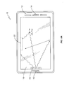
- Figure 1 is a perspective view illustrating an electronic device configured to operate according to one embodiment of the present invention.
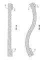
- Figures 2A and 2B are cross-sectional views of a display surface configured to operate according to one embodiment of the present invention.
- Figures 3A and 3B illustrate how the standing waves might propagate through a display if the user does not touch the display.
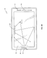
- Figures 4A and 4B illustrate how the standing waves might propagate through a display if the user touches the display at a first location on the display screen.
- Figures 5A and5B illustrate how the standing waves might propagate through a display if the user touches the display at a second location on the display screen.
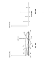
- Figure 6 is a flow chart illustrating a method of locating a user touch according to one embodiment of the present invention.
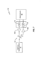
- Figure 7 is a block diagram illustrating a circuit that may be used to control the operating modes of a transducer according to one embodiment of the present invention.
- Figures 8A and 8B are perspective views of an electronic device configured to operate according to another embodiment of the present invention.
- Figure 9 is a flow chart illustrating a method of locating a user touch according to another embodiment of the present invention.
- Figure 10 shows graphs illustrating how a controller might implement a method of the present invention to determine the location of a user touch according to one embodiment.
- Figures 11A-11C show graphs that illustrate a method of resolving ambiguities when computing the location of a user touch according to one embodiment of the present invention.
- Figures 12A-12C illustrate a method of resolving ambiguities when computing the location of a user touch according to another embodiment of the present invention.
- Figures 13A-13D illustrate a method of resolving ambiguities when computing the location of a user touch according to another embodiment of the present invention.
- Figure 14 is a block diagram illustrating some of the components of an electronic device configured according to one embodiment of the present invention.
- Figure 15 shows perspective views of some exemplary types of electronic devices suitable for use with the present invention.
- the present invention provides a device that can determine the location of a user's touch on a display of the device.
- the device includes a pair of haptic transducers that are connected to a display. These haptic transducers are typically employed to implement tactile feedback to the user. However, according to the present invention, they are momentarily activated whenever the user touches the display to generate standing waves in the display. The user's touch distorts these standing waves to produce variations in the standing waves. The modified waves are then detected and measured by sensors on the display, and analyzed by a controller to determine the location of the user touch on the display.
- the sensors that detect and measure the distortions comprise a pair of microphones having a frequency response that is within the audible range of the human ear.
- microphones or other devices having a sub-audible or super-audible frequency response are used as sensors.
- the microphones that detect the sound generate signals that are digitized and sent to a controller. Based on the digitized signals, the controller computes an acoustic signature for the detected sound.
- the acoustic signature will vary in a predictable manner depending on the location of the user touch. Therefore, the controller can analyze the acoustic signature and determine the location of the user's touch based on the analysis.
- the haptic transducers perform a dual function in that they first function as a vibrator to vibrate the display, and then as a sensor to detect the distortions to those vibrations.
- a first haptic transducer is momentarily activated to generate the standing waves in the display.
- the second haptic transducer is configured to sense the distortions caused by the user's touch to those standing waves.
- the roles of the transducers are reversed such that the second haptic transducer is momentarily activated to generate the standing waves in the display, and the first haptic transducer is configured to sense the distortions caused by the user touch to those standing waves.
- Each haptic transducer provides its sensor readings to the controller, which analyzes them to determine the location of the user's touch.
- Transient waves are those that only exist for a limited time T such that standing waves do not have a chance to fully form.
- This length of time T may be influenced by a number of different factors. For example, one factor is the amount of acoustic energy that is dissipated versus the amount of acoustic energy that stored in the mechanical structure of the device. Particularly, as a greater amount of acoustic energy is lost or dissipated, standing waves will form more quickly and vice versa.
- Knowing this limited time T can be useful when considering the propagation time of acoustic energy across the display.
- a transient wave would last for a time that is shorter than it would take for the acoustic energy to propagate across the display.
- other measurements such as propagation times or times of arrival of acoustic energy can be measured with a high degree of accuracy.
- Figure 1 illustrates a perspective view of a front face of a cellular telephone device 10 configured according to one embodiment of the present invention.
- Device 10 comprises, inter alia, a set of global controls 12 to enable a user to control the functionality of device 10, as well as a microphone 14 and a speaker 16 to allow the user to communicate with one or more remote parties via a wireless communication network (not shown).
- Device 10 also comprises a display 18, first and second haptic transducers 20, 22 and a pair of sensors 24, 26, which in this embodiment, comprise a pair of microphones.
- Display 18 in this embodiment is a touch-sensitive display that is configured to detect the user's touch at different locations on the display (e.g., (X 1 , Y 1 ) and (X 2 , Y 2 )).
- the haptic transducers 20, 22 are positioned on the display 18 and along two perpendicular sides of display 18.
- the microphones 24, 26 are also placed on the display 18 along the other two perpendicular sides opposite the haptic transducers 20, 22.
- microphone 24, 26 is displaced slightly inward from the edges of the display 18 toward the center of display 18. This placement allows the microphones 24, 26 to sufficiently detect the acoustic properties of the modified vibrations, and thus, more accurately determine the location of the user's touch.
- FIGS. 2A-2B illustrate this aspect of the invention in more detail. Particularly, Figures 2A and 2B illustrate a cross sectional view of display 18 showing the haptic transducer 20 on one side and the corresponding microphone 24 on the other. Although only one haptic transducer 20 and microphone 24 is illustrated here, those skilled in the art will appreciate that this figure is merely illustrative of the operation of both haptic transducers 20, 22 and both microphones 24, 26.
- FIG 2A the user has not touched display 18 and as a result, display 18 is at rest (i.e., display 18 is not vibrating).
- the touch-sensitive display 18 generates a signal to a controller to momentarily activate both the first and second haptic transducers 20, 22 when the user touches the display 18 (e.g., at location (X 1 ,Y 1) or (X 2 , Y 2 ) seen in Figure 1 ).
- the haptic transducers 20, 22 vibrate a surface of the display 18 to create standing waves in the display surface.
- the haptic transducers 20,22 generate the standing waves at a frequency f , commonly known as the "fundamental,” and at a plurality of multiples of the fundamental, commonly known as “harmonics.”
- f frequency
- the user's touch distorts or modifies the standing waves.
- the microphones 24, 26, detect the sound of these modified standing waves, which varies in a predictable manner depending on the location of the user's touch.
- the distortions or modifications to the standing waves caused by the user touch differ based on the location of the touch relative to the haptic transducers 20, 22. That is, a user touch at a position on the display that is relatively near haptic transducer 20 (e.g., position X 2 ,Y 2 ) will distort the standing waves differently than if the user touch had occurred at another position farther away from the haptic transducer 20 (e.g., position X 1 ,Y 1 ).
- the microphones 24, 26 detect sounds created when the user touches the display 18 at either location, but would generate different signals based on the sounds because the touches occurred at different locations. As such, an acoustic signature of a given modified standing wave is unique, allowing the controller in device 10 to calculate the location of the user touch from the sound detected by the microphones 24, 26.
- Figures 3-5 illustrate this aspect of the present invention in more detail.
- the display 18 is seen along with the haptic transducer 20 and the microphone 24 for reference. Only the standing waves for the first four harmonic frequencies are shown in these figures. These are the first harmonic frequency or "fundamental" frequency f , the second harmonic frequency 2 f (i.e., twice the fundamental), the third harmonic frequency 3 f (i.e., three times the fundamental), and the fourth harmonic frequency 4 f (i.e., four times the fundamental).
- the first harmonic frequency or “fundamental" frequency f the second harmonic frequency 2 f (i.e., twice the fundamental)
- the third harmonic frequency 3 f i.e., three times the fundamental
- the fourth harmonic frequency 4 f i.e., four times the fundamental.
- Each standing wave has a node N (i.e., the point of a wave having minimal amplitude) and an anti-node AN (i.e., the point of a wave having maximum amplitude), although for illustrative purposes, the node N and the anti-node AN for only one of those waves (i.e., 3 f ) is shown. Note that while four harmonics are shown in the figures, a larger number may be present in some embodiments.
- Figure 3A illustrates the standing waves generated by the haptic transducer 20 along a longitudinal axis of display 18 as they might appear if no finger or stylus touches display 18.
- Figure 3B is a corresponding graph illustrating the amplitudes of the first four harmonic frequencies f , 2 f , 3 f , 4 f as they might appear if no user touches the display 18. As seen in Figure 3B , each harmonic frequency f , 2 f , 3 f , 4 f has a different amplitude.
- the amplitudes for each wave are readily measurable. Further, as stated previously, the user's touch will disturb these waves in predictable ways such that a unique modified wave is generated for any given touch location on the display 18. According to this embodiment of the present invention, the sound of the unique modified standing wave that is caused by the user's touch can be analyzed to determine the location of the user's touch.
- Figures 4A-4B illustrate the effects of a user touch on the generated standing waves if the user touch occurs at a position on the display pointed to by the arrow (e.g., X 1 ,Y 1 ) .
- the user's touch at position (X 1 ,Y 1 ) on display 18 reduces the amplitudes of the standing waves for the harmonic frequencies f , 2 f , and 4 f .
- the amplitude for the third harmonic frequency 3 f is not as greatly affected due to the location of the user touch. Specifically, one or more of the amplitudes are reduced depending upon how near, or how far, the touch location is from the nodes N of the harmonic frequencies.
- Figures 5A-5B illustrate the effects of a user touch at location (X 2 ,Y 2 ) on display 18, indicated by the arrow.
- the location of the user touch is very near an anti-node AN of the third harmonic 3 f , as well as near an anti-node of the fundamental frequency 1 f .
- the location is also farthest way from the nodes N of the second and fourth harmonic frequencies 2 f , 4 f . Consequently, the amplitudes of the standing waves for the first and third harmonic frequencies 1 f , 3 f are reduced more by the user's touch than are those for the second and fourth harmonic frequencies 2 f , 4 f .
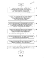
- FIG. 6 is a flow diagram illustrating a method 30 of performing one embodiment of the present invention.
- Method 30 begins when, upon detecting the user's touch on display 18 at a location (e.g., location X 1 ,Y 1 ), device 10 activates the first and second haptic transducers 20, 22 to vibrate the touch-sensitive display 18 (box 32). This causes the standing waves to propagate through display 18, which are modified in a known manner based on the location of the user touch.
- the microphones 24, 26 disposed on the display 18 detect the sound that is associated with these modified standing waves and caused by the user's touch (box 34).
- the microphones 24, 26 then send analog signals indicating the amplitude of the detected sound to processing circuitry for conversion into digitized electrical signals.
- the digitized electrical signals are then sent to a controller or other processor in device 10 (box 36).
- the controller determines the location of the user touch based on the digitized signals. As described in more detail later, the location may be determined in different ways; however in at least one embodiment, the controller computes an acoustic signature for the sound generated by the modified standing waves based on the digitized electrical signals (box 38), and analyzes the computed acoustic signature to determine the location of the user's touch (box 40).
- Determining touch location in accordance with the present invention provides benefits that conventional methods of determining touch location do not.
- the haptic transducers 20, 22, the microphones 24, 26, and the other resources that are needed to determine the location of a user's touch are activated only when a user touches the display 18.
- the display 18 may be configured to detect a user touch by sensing pressure, detecting a change in resistance, or by measuring an amount of reflected light. They do not need to be continually active and monitoring for a user touch, as is required by conventional devices that use a passive approach.
- a device using the active approach of the present invention consumes less power than does a device that employs the conventional passive acoustic approach of determining touch location.
- the method of the present invention relies on the acoustic signature of the modified standing waves, which are caused by the user touch in a given location. As such, the amount of force with which a user touches the display has a minimal effect on the ability of a controller to determine an accurate location for the touch.
- any location on display 18 can easily be computed using known mathematical processes to interpret the unique acoustical signatures of the modified standing waves.
- the present invention computes the location of the user's touch on display 18 based on the acoustic signature rather than compare it to one or more known acoustic signatures stored in memory.
- Such computations negate the need to store multiple acoustic signatures in one or more sets of tables, as well as the need to conduct an exhaustive search of those tables. Accordingly, the method of the present invention is faster at determining the location of a user touch than is a conventional device.
- each haptic transducer 20, 22 performs a dual function. Particularly, each haptic transducer 20, 22 is first used actively as a driver (i.e., in a "driver mode") to generate the standing waves in display 18, and then passively as a sensor (i.e., in a "sensor mode") to detect the distortions or modifications of the standing waves that are caused by the user's touch. Switching the haptics transducers 20, 22 between these two operating modes may be accomplished using any means known in the art. However, in one embodiment seen in Figure 7 , device 10 utilizes a mode switching circuit 50 to switch haptic transducer 20 between the "driver mode" and the "sensor mode.”
- Circuit 50 comprises a switch 52 that alternately connects and disconnects the haptics transducer 20 to a pair of amplifiers 54a, 54b.
- a Digital-to-Analog (D/A) converter 56 converts digital signals from controller 80 into analog signals for the haptics transducer 20, while an Analog to Digital (A/D) 58 converts analog signals from the haptics transducer 20 into digital signals for the controller 80.
- the controller 80 which is described in more detail later, performs the calculations necessary to determine the location of a user's touch on display 18, and generates control signals to operate switch 52 to switch the mode of the haptics transducer 20 between a driver mode and a sensor mode.
- FIGs 8A-8B illustrate this embodiment in more detail.
- device 10 momentarily activates a first one of the haptic transducers 20 in a driver mode to vibrate display 18 responsive to detecting the user touch at location (X 1 ,Y 1 ).
- the other haptic transducer 22 is left in a sensor mode to passively sense the amplitudes of the modified standing waves.
- the roles of the haptic transducers 20, 22 are reversed. That is, device 10 momentarily activates the other haptic transducer 22 in the driver mode to vibrate the display 18 and switches the first haptic transducer 20 to the sensor mode so that it can sense the resultant amplitudes of the modified standing waves.
- the standing waves are modified in a predictable manner depending upon the location of the user's touch. Based on the information provided by haptic transducers 20, 22 when in the sensor mode, a controller 80 in device 10 can accurately compute the location of the user touch on display 18.
- Figure 9 is a flow chart that illustrates a method 60 of implementing touch location on device 10 using the haptic transducers 20, 22 in alternating driver and sensor modes.
- Method 50 begins with device 10 momentarily activating first haptic transducer 20 in the driver mode responsive to detecting the user's touch (box 62). As the first haptic transducer 20 vibrates the display 18, the second haptic transducer 22 is switched to operate in the sensor mode. This allows the second haptic transducer 22 to detect the amplitudes of the standing waves generated by the first haptic transducer 20 as they are modified by the user's touch (box 64).
- the device 10 switches the first haptic transducer 20 to sensor mode and momentarily switches the second haptic transducer 22 to driver mode (box 66). While in driver mode, the second haptic transducer 22 generates the standing waves in display 18 while the first haptic transducer 20 operating in sensor mode detects the amplitudes of the resultant modified standing waves in display 18 (box 68).
- each haptic transducer 20, 22 provides analog signals to the A/D converter 58 representing the detected amplitudes of the modified standing waves.
- the A/D converter 58 converts these signals into digitized electrical signals for the controller 80 (box 70).
- Controller 80 then computes the power spectrum of the modified vibrations based on the digitized electrical signals (box 72), and determines the touch location based on those computations (box 74).
- the present invention also allows for the use of time to improve the accuracy and/or resolve ambiguities in the result.
- the display 18 has known dimensions and is manufactured from a known material. Therefore, based on the signals provided by each haptic transducer 20, 22 when operating in the sensor mode, the controller 80 can determine added information by analyzing the time of travel of the generated vibrations propagating across the display 18. This includes those vibrations or waves that reflect off a side of the display 18 towards whichever haptic transducer 20 or 22 is operating in the sensor mode. The additional information can be digitized and provided to controller 80 in device 10 to increase accuracy and/or remove ambiguities in determining the location of the user touch.
- Figures 10-13 illustrate how a controller or other processor in device 10, such as controller 80, may operate to compute the location of a user touch according to one embodiment of the present invention.
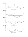
- Figure 10 shows four graphs illustrating the first four harmonic frequencies generated by the haptic transducers 20, 22.
- the first harmonic, or fundamental frequency f is seen in the graph labeled (a).
- the second, third, and fourth harmonics are seen in the graphs labeled (b), (c), and (d), respectively.
- the arrows indicate the position of a user touch on display 18.
- the solid lines indicate a standing wave as it might appear unaffected by the user's touch.
- the dotted lines indicate the same standing wave as distorted or modified by the user touch at a particular location.
- the sensors i.e., the microphones 24, 26, or the haptic transducers 20, 22 acting passively as sensors
- the sensors would detect the modified standing waves and provide analog signals representing the amplitudes of the modified standing waves to the A/D converter 58.
- the A/D converter 58 would then generate digitized samples of these signals for use by the controller 80 in device 10 according to the method of the present invention.
- controller 80 Upon receipt of the digitized signals, the controller may use any number of processes with which to compute or determine the location of the user touch on display 18. In at least one embodiment, however, controller 80 first analyzes the digitized signals to determine which region of the display 18 the touch occurred. For example, the controller 80 could determine which half of a display 18 (i.e., upper half, lower half) a touch occurred by analyzing the digitized samples of the modified standing wave associated with the fundamental frequency f . In a similar manner, the controller 80 could analyze the digitized samples of the modified standing wave associated with the second harmonic frequency 2 f to determine whether the touch occurred towards an edge of the display 18 or more towards the center of display 18. As seen in graph (b) of Figure 10 , the touch occurred more towards the center of the display 18.
- Analyzing the third and fourth harmonics 3 f and 4 f would allow the controller 80 to determine that the touch occurred in a central region of display 18, and more particularly, at or near a point on display 18 corresponding to node N of the fourth harmonic 4 f . From these exemplary graphs, it is apparent to one skilled in the art that the location of the user touch may be determined with even higher resolution and/or accuracy by analyzing the effects of the user touch on the amplitudes of a greater number of harmonic frequencies (e.g., fifth harmonic, sixth harmonic, etc.).
- a greater number of harmonic frequencies e.g., fifth harmonic, sixth harmonic, etc.
- the present invention also provides a method of resolving ambiguities when determining the location of the user's touch.
- the ambiguities may be resolved by using the acoustic signature of the standing waves that have been modified by the user's touch.
- one embodiment of the present invention analyzes wavelength ⁇ of the standing wave with fundamental frequency f ) relative to the length or width of the display 18 (i.e., the dimension of the display in either the 'X' or 'Y' direction, respectively).
- device 10 determines whether the wavelength A of the standing wave with fundamental frequency f is less than one-half the length of the display 18.
- the device 10 determines the amplitude of the standing wave that was modified or attenuated by the user touch. Amplitudes that are subject to a greater amount of attenuation indicate user touches occurring at locations that are farther away from a haptic transducer than those that are subject a lesser amount of attenuation. As previously stated, the location of the user's touch relative to a node N or anti node AN of a standing wave for a given harmonic will affect the amount of attenuation imparted on the amplitude of that standing wave.
- Figures 11A-11C illustrate this aspect in more detail.
- Figure 11A illustrates a standing wave of fundamental frequency f , whose corresponding wavelength A is approximately four times the width of display 18.
- the width of the display is approximately % of the wavelength ⁇ corresponding to the fundamental frequency f .
- Figure 11A shows the standing wave with fundamental frequency f as it might appear when the user is not touching the display 18.
- the haptics transducer is located on the right hand side of the graph, driving the acoustic signal with maximum amplitude at that location. Because the left side of the graph (the far side of the display from the haptics transducer, is % wavelength away it can be null if the display 18 is rigidly held at that edge.
- the controller can use this relationship to eliminate and/or reduce phase ambiguities that might occur when analyzing the attenuations on the higher harmonics. If the display 18 is not held rigidly but has some degree of movement, the null will be less pronounced but will still be attenuated more on the far edge than on the driven edge of the display and will still work as described.
- the present invention utilizes the phase of the modified standing waves received by the sensors such as microphone 24, 26 to resolve ambiguities.
- the sensors such as microphone 24, 26
- the present invention utilizes the phase of the modified standing waves received by the sensors such as microphone 24, 26 to resolve ambiguities.
- one of the harmonic frequencies can be analyzed to resolve ambiguities in determining the location of the user touch on display 18.
- These particular figures show the use of the third harmonic frequency 3f having a wavelength of about 1.5 times the width of the display.
- other harmonics at other wavelengths may be used as well.
- Figure 12A illustrates harmonic 3 f as it might appear if the user does not touch the display 18.
- the standing wave sensed by microphone 24 is in phase with the vibrations transmitted by the haptic transducer 20 opposite the microphone 24.
- the phase of the generated waves is distorted. Therefore, for any given harmonic frequency and any given touch location, the device 10 can resolve which phase is occurring by measuring the difference between the amplitudes at two points in time when the transmitted vibrations have a 180-degree phase difference.
- Figure 12B illustrates how the phase of the standing wave could be distorted or modified when the user touch occurs at a first location on display 18.
- Figure 12C illustrates how the phase of the standing wave could be distorted or modified when the user touch occurs at a second, different location on display 18. As seen in these figures, the phase differences are unique for each location. Thus, the device 10 can use this phase-difference information to resolve ambiguities when determining the location of the user touch.
- Figures 13A-13D Another method of resolving ambiguities while determining touch location is seen in Figures 13A-13D .
- Figure 13A illustrates a cross-sectional view of the display 18 having the haptic transducer 20 and the microphone 24 as it might appear at rest (i.e., without a standing wave applied). Responsive to a user touch, the haptic transducers 20, 22 will activate to vibrate the display 18.
- Figure 13B illustrates the generated standing wave that propagates through the display 18, while Figures 13C-13D show views of the display 18 from the perspective above the top surface.
- the positive phase portions of the standing wave propagating through display 18 are denoted using the term "UP.”
- the negative phase portion of the wave propagating through display 18 is denoted using the word "DOWN.”
- the values t 1 and t 2 denote the propagation times for the leading edges of the vibrations to reach the location of the user touch from the haptic transducers 20, 22.
- each of the two haptic transducers 20, 22 could be controlled to generate standing waves with different fundamental frequencies (e.g., f 20 and f 22 ) and corresponding sets of harmonics (e.g., 2-4 f 20 and 2-4 f 22 ). This approach allows both of the haptic transducers 20, 22 to be operated in the driver mode simultaneously.
- the microphones 24, 26, or other sensors would be able to distinguish between the modified standing waves where the sources (i.e., the haptic transducers 20, 22) are separated by 90 degrees. Alternately, the haptic transducers 20, 22 could be sequentially activated, as previously described.
- Figure 14 is a block diagram illustrating some of the components of an electronic device 10 configured according to one embodiment of the present invention.
- Device 10 comprises a programmable controller 80, a memory 82, a user input/output interface 84, and a communications interface 88.
- device 10 also comprises a pair of haptic transducers 20, 22 and a pair of sensors 24, 26, which are indicated as microphones in the embodiment of Figure 14 .
- Controller 80 generally controls the overall operation of device 10 according to programs and instructions stored in memory 82.
- the controller 80 may comprise a single microprocessor or multiple microprocessors executing firmware, software, or a combination thereof.
- the microprocessors may be general purpose microprocessors, digital signal processors, or other special purpose processors, and may further comprise special-purpose fixed or programmable logic or arithmetic units.
- the controller 80 is programmed to receive signals from the sensors 24, 26 (i.e., either the haptic transducers 20, 22 or the microphones), and analyze the signals to determine the location of a user's touch on display 18.
- the controller 80 is also programmed to resolve ambiguities as previously stated.
- Memory 82 comprises a computer-readable medium that may include both random access memory (RAM) and read-only memory (ROM). Although not specifically shown, those skilled in the art will appreciate that the memory 82 may be embodied other hardware components, such as compact disks (CDs), hard drives, tapes, and digital video disks (DVDs) that may be connected to the device 10 via an interface port (not shown). Computer program instructions and data required for operation are stored in non-volatile memory, such as EPROM, EEPROM, and/or flash memory, which may be implemented as discrete devices, stacked devices, or integrated with the controller 80. One such computer program, indicated here as application 88, allows the controller 80 to function according to one or more embodiments of the present invention.
- RAM random access memory
- ROM read-only memory
- application 88 contains computer program instructions that, when executed by controller 80, causes the controller 80 to react to the detected user's touch by activating and deactivating the haptic transducers 20, 22 and/or microphones 24, 26, as well as analyzing the resultant signals received from those sensors to determine the location of the user touch.
- the User Interface (UI) 84 includes one or more user input/output devices, such as a touch-sensitive display 18, a microphone 14, a speaker 16, and one or more global controls 12 to enable the user to interact with and control device 10.
- the communication interface 86 allows the device 10 to communicate messages and other data with one or more remote parties and/or devices.
- the communication interface 86 comprises a fully functional cellular radio transceiver that can operate according to any known standard, including the standards known generally as the Global System for Mobile Communications (GSM), the General Packet Radio Service (GPRS), cdma2000, Universal Mobile Telecommunications System (UMTS), Wideband Code Division Multiple Access (WCDMA), 3GPP Long Term Evolution (LTE), and Worldwide Interoperability for Microwave Access (WiMAX).
- GSM Global System for Mobile Communications
- GPRS General Packet Radio Service
- UMTS Universal Mobile Telecommunications System
- WCDMA Wideband Code Division Multiple Access
- LTE Long Term Evolution
- WiMAX Worldwide Interoperability for Micro
- the communication interface 86 may comprise a hardware port, such as an Ethernet port, for example, that connects device 10 to a packet data communications network.
- the communication interface 86 may comprise a wireless LAN (802.11 x) interface.
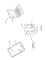
- device 10 comprises a tablet computing device, such as APPLE'S iPAD 90, or a personal computing device 92, such as a laptop or desktop computer, or a display device 94 connected to a server or other computing device.
- tablet computing device such as APPLE'S iPAD 90
- personal computing device 92 such as a laptop or desktop computer
- display device 94 connected to a server or other computing device.
- the display 18 has been described in the previous embodiments as being a touch-sensitive display. However, those skilled in the art should appreciate that a touch-sensitive display is not necessary. All that is needed is some way to indicate that a user has touched the display.
- the display 18 could comprise a Liquid Crystal Display, and the device could include a control button on the side of the housing. The user could activate/deactivate the haptic transducers by manually actuating the button, for example. Therefore, the present embodiments are to be considered in all respects as illustrative and not restrictive, and all changes coming within the meaning and equivalency range of the appended claims are intended to be embraced therein.
Landscapes
- Engineering & Computer Science (AREA)
- General Engineering & Computer Science (AREA)
- Theoretical Computer Science (AREA)
- Physics & Mathematics (AREA)
- Human Computer Interaction (AREA)
- General Physics & Mathematics (AREA)
- Acoustics & Sound (AREA)
- User Interface Of Digital Computer (AREA)
- Position Input By Displaying (AREA)
Applications Claiming Priority (1)
| Application Number | Priority Date | Filing Date | Title |
|---|---|---|---|
| US12/819,719 US8519982B2 (en) | 2010-06-21 | 2010-06-21 | Active acoustic touch location for electronic devices |
Publications (2)
| Publication Number | Publication Date |
|---|---|
| EP2397933A2 true EP2397933A2 (de) | 2011-12-21 |
| EP2397933A3 EP2397933A3 (de) | 2014-08-27 |
Family
ID=44117154
Family Applications (1)
| Application Number | Title | Priority Date | Filing Date |
|---|---|---|---|
| EP11004216.5A Withdrawn EP2397933A3 (de) | 2010-06-21 | 2011-05-20 | Aktive akustische Berührungslokalisierung für elektronische Geräte |
Country Status (2)
| Country | Link |
|---|---|
| US (1) | US8519982B2 (de) |
| EP (1) | EP2397933A3 (de) |
Cited By (3)
| Publication number | Priority date | Publication date | Assignee | Title |
|---|---|---|---|---|
| WO2014081721A1 (en) * | 2012-11-21 | 2014-05-30 | The Board Of Trustees Of The Leland Stanford Junior University | A multi-touch ultrasonic touch screen |
| WO2018149988A1 (de) * | 2017-02-16 | 2018-08-23 | Behr-Hella Thermocontrol Gmbh | Bedieneinheit für eine fahrzeugkomponente, insbesondere mensch-maschine-interface für ein fahrzeug |
| US11432059B2 (en) * | 2019-06-19 | 2022-08-30 | Samsung Display Co., Ltd. | Display device and sound providing method |
Families Citing this family (62)
| Publication number | Priority date | Publication date | Assignee | Title |
|---|---|---|---|---|
| GB0905692D0 (en) * | 2009-04-02 | 2009-05-20 | Tno | Touch sensitive device |
| FR2948471B1 (fr) * | 2009-07-21 | 2016-02-26 | Commissariat Energie Atomique | Procede et dispositif de localisation d'au moins un toucher sur une surface tactile d'un objet |
| US8624878B2 (en) | 2010-01-20 | 2014-01-07 | Apple Inc. | Piezo-based acoustic and capacitive detection |
| EP2469382B1 (de) * | 2010-12-22 | 2018-11-07 | Elo Touch Solutions, Inc. | Verfahren und Vorrichtung zur Kalibrierung von Berührungssensoren |
| US8854319B1 (en) * | 2011-01-07 | 2014-10-07 | Maxim Integrated Products, Inc. | Method and apparatus for generating piezoelectric transducer excitation waveforms using a boost converter |
| US10198097B2 (en) | 2011-04-26 | 2019-02-05 | Sentons Inc. | Detecting touch input force |
| US9639213B2 (en) | 2011-04-26 | 2017-05-02 | Sentons Inc. | Using multiple signals to detect touch input |
| US9477350B2 (en) | 2011-04-26 | 2016-10-25 | Sentons Inc. | Method and apparatus for active ultrasonic touch devices |
| US9189109B2 (en) | 2012-07-18 | 2015-11-17 | Sentons Inc. | Detection of type of object used to provide a touch contact input |
| US11327599B2 (en) | 2011-04-26 | 2022-05-10 | Sentons Inc. | Identifying a contact type |
| FR2975197B1 (fr) * | 2011-05-09 | 2013-05-24 | Univ Lille 1 Sciences & Technologies | Interface tactile vibrante transparente. |
| US10180722B2 (en) * | 2011-05-27 | 2019-01-15 | Honeywell International Inc. | Aircraft user interfaces with multi-mode haptics |
| US9348467B2 (en) * | 2011-11-15 | 2016-05-24 | Elo Touch Solutions, Inc. | Radial layout for acoustic wave touch sensor |
| US9304629B2 (en) | 2011-11-15 | 2016-04-05 | Elo Touch Solutions, Inc. | Radial transducer for acoustic wave touch sensor |
| US10235004B1 (en) * | 2011-11-18 | 2019-03-19 | Sentons Inc. | Touch input detector with an integrated antenna |
| US9594450B2 (en) | 2011-11-18 | 2017-03-14 | Sentons Inc. | Controlling audio volume using touch input force |
| US11340124B2 (en) | 2017-08-14 | 2022-05-24 | Sentons Inc. | Piezoresistive sensor for detecting a physical disturbance |
| KR101771896B1 (ko) | 2011-11-18 | 2017-08-28 | 센톤스 아이엔씨. | 국소형 햅틱 피드백 |
| US9134856B2 (en) * | 2013-01-08 | 2015-09-15 | Sony Corporation | Apparatus and method for controlling a user interface of a device based on vibratory signals |
| US9717459B2 (en) | 2013-03-04 | 2017-08-01 | Anne Bibiana Sereno | Touch sensitive system and method for cognitive and behavioral testing and evaluation |
| GB2513884B (en) | 2013-05-08 | 2015-06-17 | Univ Bristol | Method and apparatus for producing an acoustic field |
| US9459715B1 (en) | 2013-09-20 | 2016-10-04 | Sentons Inc. | Using spectral control in detecting touch input |
| US9612658B2 (en) | 2014-01-07 | 2017-04-04 | Ultrahaptics Ip Ltd | Method and apparatus for providing tactile sensations |
| US10394326B2 (en) * | 2014-03-31 | 2019-08-27 | Sony Corporation | Tactile sense presentation apparatus, signal generation device, tactile sense presentation system, and tactile sense presentation method |
| GB2530036A (en) | 2014-09-09 | 2016-03-16 | Ultrahaptics Ltd | Method and apparatus for modulating haptic feedback |
| SG11201706527QA (en) | 2015-02-20 | 2017-09-28 | Ultrahaptics Ip Ltd | Algorithm improvements in a haptic system |
| WO2016132144A1 (en) | 2015-02-20 | 2016-08-25 | Ultrahaptics Ip Limited | Perceptions in a haptic system |
| US10818162B2 (en) | 2015-07-16 | 2020-10-27 | Ultrahaptics Ip Ltd | Calibration techniques in haptic systems |
| US9851848B2 (en) | 2015-12-14 | 2017-12-26 | Microsoft Technology Licensing, Llc | Touch sensitive device casing |
| US11189140B2 (en) | 2016-01-05 | 2021-11-30 | Ultrahaptics Ip Ltd | Calibration and detection techniques in haptic systems |
| CN106249863B (zh) * | 2016-02-04 | 2019-02-12 | 北京智谷睿拓技术服务有限公司 | 交互方法、交互装置及用户设备 |
| US10531212B2 (en) | 2016-06-17 | 2020-01-07 | Ultrahaptics Ip Ltd. | Acoustic transducers in haptic systems |
| JP6992045B2 (ja) * | 2016-07-22 | 2022-01-13 | ハーマン インターナショナル インダストリーズ インコーポレイテッド | 触覚誘導システム |
| US10268275B2 (en) | 2016-08-03 | 2019-04-23 | Ultrahaptics Ip Ltd | Three-dimensional perceptions in haptic systems |
| US10755538B2 (en) | 2016-08-09 | 2020-08-25 | Ultrahaptics ilP LTD | Metamaterials and acoustic lenses in haptic systems |
| US10908741B2 (en) | 2016-11-10 | 2021-02-02 | Sentons Inc. | Touch input detection along device sidewall |
| US10296144B2 (en) | 2016-12-12 | 2019-05-21 | Sentons Inc. | Touch input detection with shared receivers |
| US10943578B2 (en) | 2016-12-13 | 2021-03-09 | Ultrahaptics Ip Ltd | Driving techniques for phased-array systems |
| US10497358B2 (en) | 2016-12-23 | 2019-12-03 | Ultrahaptics Ip Ltd | Transducer driver |
| US10126877B1 (en) | 2017-02-01 | 2018-11-13 | Sentons Inc. | Update of reference data for touch input detection |
| US10585522B2 (en) | 2017-02-27 | 2020-03-10 | Sentons Inc. | Detection of non-touch inputs using a signature |
| DE102017116012A1 (de) * | 2017-07-17 | 2019-01-17 | Fraunhofer-Gesellschaft zur Förderung der angewandten Forschung e.V. | Anzeigevorrichtungen und pixel für eine anzeigevorrichtung |
| US11580829B2 (en) | 2017-08-14 | 2023-02-14 | Sentons Inc. | Dynamic feedback for haptics |
| US11531395B2 (en) | 2017-11-26 | 2022-12-20 | Ultrahaptics Ip Ltd | Haptic effects from focused acoustic fields |
| EP3729418B1 (de) | 2017-12-22 | 2024-11-20 | Ultrahaptics Ip Ltd | Minimierung von unerwünschten antworten in haptischen systemen |
| EP3729417B1 (de) * | 2017-12-22 | 2025-09-10 | Ultrahaptics Ip Ltd | Verfolgung in haptischen systemen |
| CN110289844B (zh) | 2018-03-19 | 2021-01-29 | 华为技术有限公司 | 触压按键组件、振动传感器组件和电子设备 |
| SG11202010752VA (en) | 2018-05-02 | 2020-11-27 | Ultrahaptics Ip Ltd | Blocking plate structure for improved acoustic transmission efficiency |
| US11098951B2 (en) | 2018-09-09 | 2021-08-24 | Ultrahaptics Ip Ltd | Ultrasonic-assisted liquid manipulation |
| US11378997B2 (en) | 2018-10-12 | 2022-07-05 | Ultrahaptics Ip Ltd | Variable phase and frequency pulse-width modulation technique |
| EP3906462B1 (de) | 2019-01-04 | 2025-06-18 | Ultrahaptics IP Ltd | Haptische texturen in der luft |
| US12373033B2 (en) | 2019-01-04 | 2025-07-29 | Ultrahaptics Ip Ltd | Mid-air haptic textures |
| CN111596754B (zh) | 2019-02-20 | 2024-06-21 | 天马日本株式会社 | 触觉呈现装置 |
| US11842517B2 (en) | 2019-04-12 | 2023-12-12 | Ultrahaptics Ip Ltd | Using iterative 3D-model fitting for domain adaptation of a hand-pose-estimation neural network |
| CA3154040A1 (en) | 2019-10-13 | 2021-04-22 | Benjamin John Oliver LONG | Dynamic capping with virtual microphones |
| US11374586B2 (en) | 2019-10-13 | 2022-06-28 | Ultraleap Limited | Reducing harmonic distortion by dithering |
| US11169610B2 (en) | 2019-11-08 | 2021-11-09 | Ultraleap Limited | Tracking techniques in haptic systems |
| US11715453B2 (en) | 2019-12-25 | 2023-08-01 | Ultraleap Limited | Acoustic transducer structures |
| US11816267B2 (en) | 2020-06-23 | 2023-11-14 | Ultraleap Limited | Features of airborne ultrasonic fields |
| WO2022058738A1 (en) | 2020-09-17 | 2022-03-24 | Ultraleap Limited | Ultrahapticons |
| US12517585B2 (en) | 2021-07-15 | 2026-01-06 | Ultraleap Limited | Control point manipulation techniques in haptic systems |
| EP4345588A1 (de) | 2022-09-30 | 2024-04-03 | Bang & Olufsen | Berührungserzeugende schallprofilerfassungssysteme und verfahren |
Family Cites Families (11)
| Publication number | Priority date | Publication date | Assignee | Title |
|---|---|---|---|---|
| US6507772B1 (en) * | 1998-01-02 | 2003-01-14 | Perdec Pty. Ltd. | Sensor device |
| CA2392431C (en) * | 1999-12-23 | 2007-11-13 | New Transducers Limited | Contact sensitive device |
| GB0116310D0 (en) * | 2001-07-04 | 2001-08-29 | New Transducers Ltd | Contact sensitive device |
| US6741237B1 (en) * | 2001-08-23 | 2004-05-25 | Rockwell Automation Technologies, Inc. | Touch screen |
| US7277087B2 (en) * | 2003-12-31 | 2007-10-02 | 3M Innovative Properties Company | Touch sensing with touch down and lift off sensitivity |
| KR20070097675A (ko) * | 2006-03-28 | 2007-10-05 | 삼성전자주식회사 | 표시 패널 |
| US20090273583A1 (en) * | 2008-05-05 | 2009-11-05 | Sony Ericsson Mobile Communications Ab | Contact sensitive display |
| US8743091B2 (en) * | 2008-07-31 | 2014-06-03 | Apple Inc. | Acoustic multi-touch sensor panel |
| DE112010002072T5 (de) * | 2009-05-22 | 2012-10-11 | Semiconductor Components Industries, Llc | Verfahren und Vorrichtung zum Detektieren eines Haltezustands auf einer akustischen Berührungsoberfläche |
| US9696856B2 (en) * | 2009-09-29 | 2017-07-04 | Elo Touch Solutions, Inc. | Method and apparatus for detecting simultaneous touch events on a bending-wave touchscreen |
| US8749531B2 (en) * | 2010-03-31 | 2014-06-10 | Blackberry Limited | Method for receiving input on an electronic device and outputting characters based on sound stroke patterns |
-
2010
- 2010-06-21 US US12/819,719 patent/US8519982B2/en not_active Expired - Fee Related
-
2011
- 2011-05-20 EP EP11004216.5A patent/EP2397933A3/de not_active Withdrawn
Non-Patent Citations (1)
| Title |
|---|
| None |
Cited By (4)
| Publication number | Priority date | Publication date | Assignee | Title |
|---|---|---|---|---|
| WO2014081721A1 (en) * | 2012-11-21 | 2014-05-30 | The Board Of Trustees Of The Leland Stanford Junior University | A multi-touch ultrasonic touch screen |
| WO2018149988A1 (de) * | 2017-02-16 | 2018-08-23 | Behr-Hella Thermocontrol Gmbh | Bedieneinheit für eine fahrzeugkomponente, insbesondere mensch-maschine-interface für ein fahrzeug |
| US10866644B2 (en) | 2017-02-16 | 2020-12-15 | Behr-Hella Thermocontrol Gmbh | Operating unit for a vehicle component, in particular human-machine interface for a vehicle |
| US11432059B2 (en) * | 2019-06-19 | 2022-08-30 | Samsung Display Co., Ltd. | Display device and sound providing method |
Also Published As
| Publication number | Publication date |
|---|---|
| US20110310028A1 (en) | 2011-12-22 |
| EP2397933A3 (de) | 2014-08-27 |
| US8519982B2 (en) | 2013-08-27 |
Similar Documents
| Publication | Publication Date | Title |
|---|---|---|
| US8519982B2 (en) | Active acoustic touch location for electronic devices | |
| US20120081337A1 (en) | Active Acoustic Multi-Touch and Swipe Detection for Electronic Devices | |
| US9811212B2 (en) | Ultrasound sensing of proximity and touch | |
| CN100380302C (zh) | 接触传感装置及其方法 | |
| EP2417511B1 (de) | Berührungsempfindliche vorrichtung | |
| US7157649B2 (en) | Contact sensitive device | |
| US9851848B2 (en) | Touch sensitive device casing | |
| KR101654008B1 (ko) | 음향신호 처리를 이용한 모바일 기기 및 상기 모바일 기기에서 수행되는 음향 신호 처리 방법 | |
| EP3979611B1 (de) | Ultraschallverarbeitungsverfahren und -vorrichtung, elektronische vorrichtung und computerlesbares medium | |
| US11276251B2 (en) | Selective fingerprint sensor activation | |
| CN105487725A (zh) | 电子设备及其控制方法 | |
| KR101340028B1 (ko) | 사용자 단말의 터치 검출 방법, 장치 및 이를 이용한 사용자 단말 | |
| US20210397801A1 (en) | Techniques for beamforming pressure waves | |
| CN102778981A (zh) | 触摸检测系统 | |
| WO2012102026A1 (ja) | 入力装置 | |
| Kang et al. | Feasibility study on multi-touch ultrasound large-panel touchscreen using guided lamb waves | |
| CN113574911B (zh) | 一种耳机及其佩戴状态的检测方法 | |
| WO2019185015A1 (zh) | 一种压电传感器信号噪声去除方法 | |
| CN108763408B (zh) | 音频信号处理方法及相关产品 | |
| KR20130005335A (ko) | 터치 압력 측정 방법 | |
| GB2580780A (en) | Methods and apparatus for configuring multiple microphones in an electronic communication device | |
| HK1161648B (en) | Touch sensitive device | |
| HK1161648A (en) | Touch sensitive device |
Legal Events
| Date | Code | Title | Description |
|---|---|---|---|
| AK | Designated contracting states |
Kind code of ref document: A2 Designated state(s): AL AT BE BG CH CY CZ DE DK EE ES FI FR GB GR HR HU IE IS IT LI LT LU LV MC MK MT NL NO PL PT RO RS SE SI SK SM TR |
|
| AX | Request for extension of the european patent |
Extension state: BA ME |
|
| PUAI | Public reference made under article 153(3) epc to a published international application that has entered the european phase |
Free format text: ORIGINAL CODE: 0009012 |
|
| PUAL | Search report despatched |
Free format text: ORIGINAL CODE: 0009013 |
|
| AK | Designated contracting states |
Kind code of ref document: A3 Designated state(s): AL AT BE BG CH CY CZ DE DK EE ES FI FR GB GR HR HU IE IS IT LI LT LU LV MC MK MT NL NO PL PT RO RS SE SI SK SM TR |
|
| AX | Request for extension of the european patent |
Extension state: BA ME |
|
| RIC1 | Information provided on ipc code assigned before grant |
Ipc: G06F 3/01 20060101ALI20140721BHEP Ipc: G06F 3/043 20060101AFI20140721BHEP |
|
| 17P | Request for examination filed |
Effective date: 20150227 |
|
| RBV | Designated contracting states (corrected) |
Designated state(s): AL AT BE BG CH CY CZ DE DK EE ES FI FR GB GR HR HU IE IS IT LI LT LU LV MC MK MT NL NO PL PT RO RS SE SI SK SM TR |
|
| 17Q | First examination report despatched |
Effective date: 20150414 |
|
| STAA | Information on the status of an ep patent application or granted ep patent |
Free format text: STATUS: THE APPLICATION IS DEEMED TO BE WITHDRAWN |
|
| 18D | Application deemed to be withdrawn |
Effective date: 20171201 |