EP2397828A1 - Physical quantity sensor - Google Patents
Physical quantity sensor Download PDFInfo
- Publication number
- EP2397828A1 EP2397828A1 EP10755591A EP10755591A EP2397828A1 EP 2397828 A1 EP2397828 A1 EP 2397828A1 EP 10755591 A EP10755591 A EP 10755591A EP 10755591 A EP10755591 A EP 10755591A EP 2397828 A1 EP2397828 A1 EP 2397828A1
- Authority
- EP
- European Patent Office
- Prior art keywords
- vibrator
- deformable body
- strain
- physical quantity
- quantity sensor
- Prior art date
- Legal status (The legal status is an assumption and is not a legal conclusion. Google has not performed a legal analysis and makes no representation as to the accuracy of the status listed.)
- Withdrawn
Links
Images





Classifications
-
- G—PHYSICS
- G01—MEASURING; TESTING
- G01L—MEASURING FORCE, STRESS, TORQUE, WORK, MECHANICAL POWER, MECHANICAL EFFICIENCY, OR FLUID PRESSURE
- G01L1/00—Measuring force or stress, in general
- G01L1/18—Measuring force or stress, in general using properties of piezo-resistive materials, i.e. materials of which the ohmic resistance varies according to changes in magnitude or direction of force applied to the material
- G01L1/183—Measuring force or stress, in general using properties of piezo-resistive materials, i.e. materials of which the ohmic resistance varies according to changes in magnitude or direction of force applied to the material by measuring variations of frequency of vibrating piezo-resistive material
Definitions
- the present invention relates to a physical quantity sensor for detecting strain and tension acting on an object.
- FIG. 6 is a cross-sectional view of conventional physical quantity sensor 501 described in Patent Literature 1.
- Insulating layer 222 made of silicon oxide or silicon nitride is formed on a surface of semiconductor substrate 1 made of material including silicon.
- a vibration-element portion which has lower electrode 3 and upper electrode 5 made of polysilicon or metal are formed on a surface of insulating layer 222.
- Upper electrode 5 is an elastic body having a ribbon shape, and has both ends in longitudinal direction fixed to the surface of insulating layer 222.
- a central portion of upper electrode 5 faces lower electrode 3 via cavity 4.
- Electronic circuit 6 with the vibration-element portion is formed unitarily on semiconductor substrate 1.
- Cavity 7 is provided in a substantially central portion of semiconductor substrate 1. Both lateral sides of cavity 7 are fixed to object 8 to be measured in strain and tension.
- a portion of semiconductor substrate 1 located above cavity 7 is thin.
- a physical quantity sensor includes a deformable body in which strain occurs in response to a stress applied thereto, a vibrator vibrating with a frequency according to the strain or with an amplitude according to the strain, and a processor processing a signal output from the vibrator.
- the vibrator is mounted to the deformable body such that the strain transmits to the vibrator.
- the processor is bonded to the deformable body such that the strain does not substantially transmit to the processor.
- This physical quantity sensor can stably detects strain and tension acting on an object.
- Figs. 1A and 1B are a top view and a side view of physical quantity sensor 1001 according to an exemplary embodiment of the present invention, respectively.
- Fig. 2 is a cross-sectional view of physical quantity sensor 1001 taken along line 2-2 shown in Fig. 1A .
- Deformable body 21 is made of metal, such as stainless steel, and generates strain by a stress applied thereto.
- Flexible substrate 22 made of flexible material, such as polyimide film, is provided on upper surface 21A of deformable body 21.
- Vibrator 23 and processor 24 are mounted onto flexible substrate 22. Vibrator 23 vibrates with a vibration frequency that changes according to the amount of the strain occurring in deformable body 21.
- Processor 24 includes electronic components, such as an integrated circuit (IC) and a resistor, and processes a signal output from vibrator 23.
- Package 25 made of ceramic or metal is mounted to deformable body 21 so as to entirely accommodate and protect vibrator 23 and processor 24.
- Fig. 3A is a top view of vibrator 23.
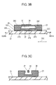
- Fig. 3B is a cross-sectional view of vibrator 23 taken along line 3B-3B shown in Fig. 3A .
- Fig. 3C is a cross-sectional view of vibrator 23 taken along line 3C-3C shown in Fig. 3A .
- Fig. 3D is an enlarged cross-sectional view of beam portion 27 of vibrator 23.
- Insulating layer 123 made of silicon oxide or silicon nitride is formed on a surface of vibrator 23.
- Vibrator 23 includes: beam portion 27 having a bar shape, and mounting body 28 surrounding beam portion 27.
- Vibrator 23 including beam portion 27 and mounting body 28 can be formed by etching a semiconductor substrate, such as a silicon substrate.
- Beam portion 27 extends in longitudinal direction 23C, and has ends 27C and 27D located in opposite to each other.
- Mounting body 28 has fixing portions 28C and 28D to which ends 27C and 27D are fixed, respectively.
- Beam portion 27 is configured to vibrate while ends 27C and 27D are fixed to fixing portions 28C and 28D, respectively.
- Detecting electrode 30 is formed at end 27D of beam portion 27.
- Driving electrode 29 is formed at central portion 27E between ends 27C and 27D of beam portion 27.
- Driving electrode 29 and detecting electrode 30 are coupled with lands 31 via wiring patterns.
- Fixing portions 28C and 28D are joined to deformable body 21 with joining materials 32C and 32D, respectively, thereby fixing vibrator 23,.
- Joining materials 32C and 32D have a large shear modulus, and allow the strain occurring in deformable body 21 to transmit to vibrator 23.
- joining materials 32C and 32D are made of rigid material, such as metal-based joining material, such as Au-Au junction (having shear modulus of about 30 GPa), and epoxy resin having a shear modulus of about 3 GPa).
- metal-based joining material such as Au-Au junction (having shear modulus of about 30 GPa), and epoxy resin having a shear modulus of about 3 GPa).
- vibrator 23 further includes lower electrode 127 disposed on the surface of beam portion 27, and piezoelectric layer 227 composed of a piezoelectric material such as PZT disposed on lower electrode 127.
- Driving electrode 29 and detecting electrode 30 are disposed on piezoelectric layer 227.
- While vibrator 23 performs the string vibration as described above, when an expanding strain occurs in deformable body 21 in directions 1001A and 1001B opposed to each other along longitudinal direction 23C, fixing portions 28C and 28D are displaced in directions 1001A and 1001B, respectively, to generate strain. Since beam portion 27 is thinner than fixing portions 28C and 28D, larger strain occurs in beam portion 27 than a strain that occurs in mounting body 28. That is, ends 27C and 27D of beam portion 27 are displaced in directions 1001A and 1001B, respectively, to cause tension in beam portion 27. This tension changes the frequency or the amplitude of the string vibration of beam portion 27.
- Detecting electrode 30 outputs a signal according to the frequency and amplitude of the vibration.
- Processor 24 detects the strain occurring in deformable body 21, by sensing the frequency or amplitude of the vibration based on the signal output from detecting electrode 30.
- vibrator 23 is disposed to deformable body 21 such that the strain occurring in deformable body 21 transmits to the vibrator, and the vibrator vibrates with a frequency according to the strain or with amplitude according to the strain.
- Processor 24 is bonded to deformable body 21 via flexible substrate 22 such that the strain does not substantially transmit to the circuit. The circuit processes the signal output from vibrator 23.
- Package 25 is mounted to deformable body 21 such that the strain does not substantially transmit to the package, and accommodates vibrator 23 and processor 24. As shown in Fig. 4 , adhesive 35 with a small shear modulus joins package 25 to deformable body 21. Joining materials 32C and 32D joins vibrator 23 to deformable body 21, and have a larger shear modulus than adhesive 35.
- Adhesive 135 bonds processor 24 to deformable body 21 via flexible substrate 22, and has a smaller shear modulus than joining materials 32C and 32D. Processor 24 is mounted onto flexible substrate 22. Adhesive 135 fixes flexible substrate 22 to deformable body 21.
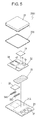
- FIG. 4 is an exploded perspective view of physical quantity sensor 1001.
- vibrator 23 is fixed to deformable body 21 with joining materials 32C and 32D.
- Processor 24 including an IC and a resistor is mounted onto flexible substrate 22.
- Adhesive 33 is made of material, such as silicone resin having shear modulus of about 0.01 GPa, having a smaller shear modulus than that of joining materials 32C and 32D. The adhesive, therefore, does not substantially allow the strain occurring in deformable body 21 to transmit to processor 24. Opening 34 through which vibrator 23 passes is formed in flexible substrate 22. Lands 31 of vibrator 23 are coupled with flexible substrate 22 by wire bonding or inner leads protruding inward from around opening 34. This structure maintains electrical connection of vibrator 23 with flexible substrate 22 even if strain occurs in deformable body 21 to displace flexible substrate 22.
- bottom portion 25C and bottom portion 25D of package 25 are fixed to deformable body 21 and flexible substrate 22 with adhesive 35 and adhesive 135, respectively, thereby allowing the package to entirely accommodate and protect vibrator 23 and processor 24.
- Adhesive 35 is made of material, such as silicone resin, having a smaller shear modulus than materials of joining materials 32C and 32D. This configuration protects vibrator 23 and processor 24 from water and dust. Adhesive 35 can prevent the strain occurring in deformable body 21 from transmitting to package 25. Consequently, package 25 does not restrain the strain occurring in deformable body 21, and allows vibrator 23 to accurately detect the strain occurring in deformable body 21.
- the height of package 25 is smaller at bottom portion 25C than at bottom portion 25D by the thickness of flexible substrate 22.
- Physical quantity sensor 1001 can accurately detect the strain occurring in deformable body 21 with vibrator 23.
- Adhesive 33 prevents the strain from transmitting to processor 24, and hence, reduces changes of circuit values of circuit elements of processor 24. This stabilizes the detection of strain and tension acting on an object.
- the strain occurring in deformable body 21 can be absorbed by both flexible substrate 22 and adhesive 33, it is possible to further reduce changes, caused by strain, in circuit values of circuit elements of processor 24. This stabilizes the detection of strain and tension acting on an object.
- Fig. 5 is an exploded perspective view of another physical quantity sensor 2001 according to the embodiment.
- components identical to those of physical quantity sensor 1001 shown in Fig. 4 are denoted by the same numerals.
- External connection terminals 37 are disposed at an end portion of deformable body 21.
- External connection terminals 37 can be formed by applying, by printing, insulating paste of glass on the end portion of deformable body 21, and then printing conductive paste, such as silver paste, on the applied insulating paste.
- the terminals have a thickness ranging from about 10 ⁇ m to 30 ⁇ m.
- a method of manufacturing physical quantity sensor 2001 will be described below with reference to Fig. 5 .
- vibrator 23 is fixed to deformable body 21 with joining materials 32C and 32D.
- Processor 24 is mounted to flexible substrate 22.
- Adhesive 33 is made of material, such as silicone resin having a shear modulus of about 0.01 GPa, having a smaller shear modulus than that of joining materials 32C and 32D. The adhesive, therefore, does not substantially allow the strain occurring in deformable body 21 to transmit to processor 24. Opening 34 through which vibrator 23 passes is formed in flexible substrate 22. Lands 31 of vibrator 23 are coupled with flexible substrate 22 by wire bonding or inner leads protruding inward from around opening 34. This structure maintains the electrical connection of vibrator 23 with flexible substrate 22 even if strain occurring in deformable body 21 displaces flexible substrate 22.
- flexible substrate 22 is electrically coupled with external connection terminals 37 by, e.g. wire bonding.
- package 25 is fixed over both deformable body 21 and flexible substrate 22 with adhesive 235, such as a silicone resin, having a small shear modulus, thereby allowing the package to entirely accommodate and protect vibrator 23 and processor 24.
- adhesive 235 such as a silicone resin, having a small shear modulus
- Adhesive 235 can prevent the strain occurring in deformable body 21 from transmitting to package 25. Consequently, package 25 does not reduce the strain occurring in deformable body 21, hence allowing vibrator 23 to accurately detect the strain occurring in deformable body 21.
- external connection terminals 37 are formed by printing on deformable body 21, steps produced where external connection terminals 37 contact package 25 is negligible relative to the thickness of adhesive 235. Therefore, there is no need for locally modifying the height of package 25 by processing the bottom portion thereof.
- Physical quantity sensor 2001 can accurately detect the strain occurring in deformable body 21 with vibrator 23.
- Adhesive 33 prevents the strain from transmitting to processor 24, and hence, reduces changes in circuit values of circuit elements of processor 24, thereby allowing the detection of strain and tension acting on an object stably.
- a physical quantity sensor according to the present invention is useful for a physical quantity sensor accurately detecting strain and tension acting on an object.
Landscapes
- Physics & Mathematics (AREA)
- General Physics & Mathematics (AREA)
- Pressure Sensors (AREA)
- Micromachines (AREA)
- Measurement Of Mechanical Vibrations Or Ultrasonic Waves (AREA)
Abstract
A physical quantity sensor includes a deformable body in which strain occurs in response to a stress applied thereto, a vibrator vibrating with a frequency according to the strain or with an amplitude according to the strain, and a processor processing a signal output from the vibrator. The vibrator is mounted to the deformable body such that the strain transmits to the vibrator. The processor is bonded to the deformable body such that the strain does not substantially transmit to the processor. This physical quantity sensor can stably detects strain and tension acting on an object.
Description
- The present invention relates to a physical quantity sensor for detecting strain and tension acting on an object.
- Physical quantity sensors of high performance and small size for detecting strain and tension acting on an object, have been recently developed by applying a micromachine technologies.
Fig. 6 is a cross-sectional view of conventionalphysical quantity sensor 501 described in Patent Literature 1. Insulatinglayer 222 made of silicon oxide or silicon nitride is formed on a surface of semiconductor substrate 1 made of material including silicon. A vibration-element portion which haslower electrode 3 andupper electrode 5 made of polysilicon or metal are formed on a surface ofinsulating layer 222.Upper electrode 5 is an elastic body having a ribbon shape, and has both ends in longitudinal direction fixed to the surface ofinsulating layer 222. A central portion ofupper electrode 5 faceslower electrode 3 viacavity 4. Electronic circuit 6 with the vibration-element portion is formed unitarily on semiconductor substrate 1. Cavity 7 is provided in a substantially central portion of semiconductor substrate 1. Both lateral sides of cavity 7 are fixed to object 8 to be measured in strain and tension. A portion of semiconductor substrate 1 located above cavity 7 is thin. - When an alternating-current voltage having a frequency equal to a natural frequency of the central portion of
upper electrode 5 is applied betweenlower electrode 3 andupper electrode 5 of the vibration-element portion, the central portion ofupper electrode 5 resonates and vibrate with a specific frequency and amplitude. This is caused by an interaction of an elastic stress ofupper electrode 5 with an electrostatic attraction generated betweenlower electrode 3 andupper electrode 5. While the vibration-element portion vibrates, when an elongation strain occurs in object 8 indirections upper electrode 5 fixed to semiconductor substrate 1 viainsulating layer 222 is enlarged in thesame directions upper electrode 5 is larger than that occurring in both the lateral side portions of cavity 7. Thus, a tension is applied in the central portion ofupper electrode 5 and changes the frequency or amplitude of the vibration of the central portion ofupper electrode 5. The variations in frequency or amplitude of the vibration with electronic circuit 6 are processed to determine the strain and tension occurring in object 8. - However, in conventional
physical quantity sensor 501, since electronic circuit 6 is unitarily formed on semiconductor substrate 1, the strain occurring in both the lateral side portions of cavity 7 may change circuit constants of circuit elements, such as resistors, that configure electronic circuit 6. The change will make the circuit unstable, leading to a possible malfunction thereon. Moreover, since the vibration-element portion and electronic circuit 6 are exposed, moisture or dust can adhere to the vibration-element portion and electronic circuit 6, thereby preventing the sensor from functioning. -
- Patent Literature 1: Japanese Patent Laid-Open Publication No.
07-333077 - A physical quantity sensor includes a deformable body in which strain occurs in response to a stress applied thereto, a vibrator vibrating with a frequency according to the strain or with an amplitude according to the strain, and a processor processing a signal output from the vibrator. The vibrator is mounted to the deformable body such that the strain transmits to the vibrator. The processor is bonded to the deformable body such that the strain does not substantially transmit to the processor.
- This physical quantity sensor can stably detects strain and tension acting on an object.
-
-
Fig. 1A is a top view of a physical quantity sensor according to an exemplary embodiment of the present invention. -
Fig. 1B is a side view of the physical quantity sensor according to the embodiment. -
Fig. 2 is a cross-sectional view of the physical quantity sensor taken along line 2-2 shown inFig. 1A . -
Fig. 3A is a top view of a vibrator of the physical quantity sensor according to the embodiment. -
Fig. 3B is a cross-sectional view of the vibrator taken alongline 3B-3B shown inFig. 3A . -
Fig. 3C is a cross-sectional view of the vibrator taken alongline 3C-3C shown inFig. 3A . -
Fig. 3D is an enlarged cross-sectional view of the vibrator shown inFig. 3B . -
Fig. 4 is an exploded perspective view of the physical quantity sensor according to the embodiment. -
Fig. 5 is an exploded perspective view of another physical quantity sensor according to the embodiment. -
Fig. 6 is a cross-sectional view of a conventional physical quantity sensor. -
Figs. 1A and 1B are a top view and a side view ofphysical quantity sensor 1001 according to an exemplary embodiment of the present invention, respectively.Fig. 2 is a cross-sectional view ofphysical quantity sensor 1001 taken along line 2-2 shown inFig. 1A .Deformable body 21 is made of metal, such as stainless steel, and generates strain by a stress applied thereto.Flexible substrate 22 made of flexible material, such as polyimide film, is provided onupper surface 21A ofdeformable body 21.Vibrator 23 andprocessor 24 are mounted ontoflexible substrate 22.Vibrator 23 vibrates with a vibration frequency that changes according to the amount of the strain occurring indeformable body 21.Processor 24 includes electronic components, such as an integrated circuit (IC) and a resistor, and processes a signal output fromvibrator 23.Package 25 made of ceramic or metal is mounted todeformable body 21 so as to entirely accommodate and protectvibrator 23 andprocessor 24. -
Fig. 3A is a top view ofvibrator 23.Fig. 3B is a cross-sectional view ofvibrator 23 taken alongline 3B-3B shown inFig. 3A .Fig. 3C is a cross-sectional view ofvibrator 23 taken alongline 3C-3C shown inFig. 3A .Fig. 3D is an enlarged cross-sectional view ofbeam portion 27 ofvibrator 23. Insulatinglayer 123 made of silicon oxide or silicon nitride is formed on a surface ofvibrator 23.Vibrator 23 includes:beam portion 27 having a bar shape, and mountingbody 28 surroundingbeam portion 27.Vibrator 23 includingbeam portion 27 and mountingbody 28 can be formed by etching a semiconductor substrate, such as a silicon substrate.Beam portion 27 extends inlongitudinal direction 23C, and has ends 27C and 27D located in opposite to each other. Mountingbody 28 has fixingportions Beam portion 27 is configured to vibrate while ends 27C and 27D are fixed to fixingportions electrode 30 is formed atend 27D ofbeam portion 27. Drivingelectrode 29 is formed atcentral portion 27E between ends 27C and 27D ofbeam portion 27. Drivingelectrode 29 and detectingelectrode 30 are coupled withlands 31 via wiring patterns. Fixingportions deformable body 21 with joiningmaterials vibrator 23,. Joiningmaterials deformable body 21 to transmit tovibrator 23. Specifically, joiningmaterials vibrator 23 with a strain substantially identical to the strain occurring indeformable body 21, hence allowingvibrator 23 to accurately detect the strain occurring indeformable body 21. - As shown in
Fig. 3D ,vibrator 23 further includeslower electrode 127 disposed on the surface ofbeam portion 27, andpiezoelectric layer 227 composed of a piezoelectric material such as PZT disposed onlower electrode 127. Drivingelectrode 29 and detectingelectrode 30 are disposed onpiezoelectric layer 227. - An operation of
physical quantity sensor 1001 will be described below. When an alternating-current (AC) voltage having a frequency identical to a natural frequency ofbeam portion 27 is applied betweenlower electrode 127 and drivingelectrode 29,beam portion 27 resonates to perform a string vibration with a specific frequency and amplitude while nodes of the vibration is located at ends 27C and 27D and an antinode is located atcentral portion 27E. - While
vibrator 23 performs the string vibration as described above, when an expanding strain occurs indeformable body 21 indirections longitudinal direction 23C, fixingportions directions beam portion 27 is thinner than fixingportions beam portion 27 than a strain that occurs in mountingbody 28. That is, ends 27C and 27D ofbeam portion 27 are displaced indirections beam portion 27. This tension changes the frequency or the amplitude of the string vibration ofbeam portion 27. - Detecting
electrode 30 outputs a signal according to the frequency and amplitude of the vibration.Processor 24 detects the strain occurring indeformable body 21, by sensing the frequency or amplitude of the vibration based on the signal output from detectingelectrode 30. - As described above,
vibrator 23 is disposed todeformable body 21 such that the strain occurring indeformable body 21 transmits to the vibrator, and the vibrator vibrates with a frequency according to the strain or with amplitude according to the strain.Processor 24 is bonded todeformable body 21 viaflexible substrate 22 such that the strain does not substantially transmit to the circuit. The circuit processes the signal output fromvibrator 23. -
Package 25 is mounted todeformable body 21 such that the strain does not substantially transmit to the package, and accommodatesvibrator 23 andprocessor 24. As shown inFig. 4 , adhesive 35 with a small shear modulus joinspackage 25 todeformable body 21. Joiningmaterials vibrator 23 todeformable body 21, and have a larger shear modulus than adhesive 35. - Joining
materials vibrator 23 todeformable body 21. Adhesive 135bonds processor 24 todeformable body 21 viaflexible substrate 22, and has a smaller shear modulus than joiningmaterials Processor 24 is mounted ontoflexible substrate 22. Adhesive 135 fixesflexible substrate 22 todeformable body 21. - A method of manufacturing
physical quantity sensor 1001 will be described below.Fig. 4 is an exploded perspective view ofphysical quantity sensor 1001. - First,
vibrator 23 is fixed todeformable body 21 with joiningmaterials Processor 24 including an IC and a resistor is mounted ontoflexible substrate 22. - Next,
flexible substrate 22 is fixed todeformable body 21 withadhesive 33.Adhesive 33 is made of material, such as silicone resin having shear modulus of about 0.01 GPa, having a smaller shear modulus than that of joiningmaterials deformable body 21 to transmit toprocessor 24.Opening 34 through which vibrator 23 passes is formed inflexible substrate 22.Lands 31 ofvibrator 23 are coupled withflexible substrate 22 by wire bonding or inner leads protruding inward from around opening 34. This structure maintains electrical connection ofvibrator 23 withflexible substrate 22 even if strain occurs indeformable body 21 to displaceflexible substrate 22. - Next,
bottom portion 25C andbottom portion 25D ofpackage 25 are fixed todeformable body 21 andflexible substrate 22 with adhesive 35 and adhesive 135, respectively, thereby allowing the package to entirely accommodate and protectvibrator 23 andprocessor 24.Adhesive 35 is made of material, such as silicone resin, having a smaller shear modulus than materials of joiningmaterials vibrator 23 andprocessor 24 from water and dust.Adhesive 35 can prevent the strain occurring indeformable body 21 from transmitting topackage 25. Consequently,package 25 does not restrain the strain occurring indeformable body 21, and allowsvibrator 23 to accurately detect the strain occurring indeformable body 21. The height ofpackage 25 is smaller atbottom portion 25C than atbottom portion 25D by the thickness offlexible substrate 22. -
Physical quantity sensor 1001 can accurately detect the strain occurring indeformable body 21 withvibrator 23.Adhesive 33 prevents the strain from transmitting toprocessor 24, and hence, reduces changes of circuit values of circuit elements ofprocessor 24. This stabilizes the detection of strain and tension acting on an object. Moreover, since the strain occurring indeformable body 21 can be absorbed by bothflexible substrate 22 and adhesive 33, it is possible to further reduce changes, caused by strain, in circuit values of circuit elements ofprocessor 24. This stabilizes the detection of strain and tension acting on an object. -
Fig. 5 is an exploded perspective view of anotherphysical quantity sensor 2001 according to the embodiment. InFig. 5 , components identical to those ofphysical quantity sensor 1001 shown inFig. 4 are denoted by the same numerals.External connection terminals 37 are disposed at an end portion ofdeformable body 21.External connection terminals 37 can be formed by applying, by printing, insulating paste of glass on the end portion ofdeformable body 21, and then printing conductive paste, such as silver paste, on the applied insulating paste. The terminals have a thickness ranging from about 10 µm to 30 µm. - A method of manufacturing
physical quantity sensor 2001 will be described below with reference toFig. 5 . - First,
vibrator 23 is fixed todeformable body 21 with joiningmaterials Processor 24 is mounted toflexible substrate 22. - Next,
flexible substrate 22 is fixed todeformable body 21 withadhesive 33.Adhesive 33 is made of material, such as silicone resin having a shear modulus of about 0.01 GPa, having a smaller shear modulus than that of joiningmaterials deformable body 21 to transmit toprocessor 24.Opening 34 through which vibrator 23 passes is formed inflexible substrate 22.Lands 31 ofvibrator 23 are coupled withflexible substrate 22 by wire bonding or inner leads protruding inward from around opening 34. This structure maintains the electrical connection ofvibrator 23 withflexible substrate 22 even if strain occurring indeformable body 21 displacesflexible substrate 22. - Then,
flexible substrate 22 is electrically coupled withexternal connection terminals 37 by, e.g. wire bonding. - Next,
package 25 is fixed over bothdeformable body 21 andflexible substrate 22 withadhesive 235, such as a silicone resin, having a small shear modulus, thereby allowing the package to entirely accommodate and protectvibrator 23 andprocessor 24. This configuration protectsvibrator 23 andprocessor 24 from water, dust, and the like. Adhesive 235 can prevent the strain occurring indeformable body 21 from transmitting topackage 25. Consequently,package 25 does not reduce the strain occurring indeformable body 21, hence allowingvibrator 23 to accurately detect the strain occurring indeformable body 21. Sinceexternal connection terminals 37 are formed by printing ondeformable body 21, steps produced whereexternal connection terminals 37contact package 25 is negligible relative to the thickness ofadhesive 235. Therefore, there is no need for locally modifying the height ofpackage 25 by processing the bottom portion thereof. -
Physical quantity sensor 2001 can accurately detect the strain occurring indeformable body 21 withvibrator 23.Adhesive 33 prevents the strain from transmitting toprocessor 24, and hence, reduces changes in circuit values of circuit elements ofprocessor 24, thereby allowing the detection of strain and tension acting on an object stably. - A physical quantity sensor according to the present invention is useful for a physical quantity sensor accurately detecting strain and tension acting on an object.
-
- 21
- Deformable Body
- 22
- Flexible Substrate
- 23
- Vibrator
- 24
- Processor
- 25
- Package
- 32C
- Joining Material
- 32D
- Joining Material
- 33
- Adhesive
- 35
- Adhesive
- 135
- Adhesive
- 235
- Adhesive
Claims (8)
- A physical quantity sensor comprising:a deformable body in which strain occurs in response to a stress applied thereto;a vibrator mounted to the deformable body such that the strain transmits to the vibrator, the vibrator vibrating with a frequency according to the strain or with an amplitude according to the strain; anda processor bonded to the deformable body such that the strain does not substantially transmit to the processor, the processor processing a signal output from the vibrator.
- The physical quantity sensor according to claim 1, further comprising a package mounted to the deformable body such that the strain does not substantially transmit to the package, the package accommodating the vibrator and the processor.
- The physical quantity sensor according to claim 2, further comprising an adhesive joining the package to the deformable body, the adhesive having a small shear modulus.
- The physical quantity sensor according to claim 2, further comprising a joining material joining the vibrator to the deformable body, the joining material having a larger shear modulus than the adhesive.
- The physical quantity sensor according to claim 1, further comprising a joining material joining the vibrator to the deformable body, the joining material having a large shear modulus.
- The physical quantity sensor according to claim 5, further comprising an adhesive bonding the processor to the deformable body, the adhesive having a smaller shear modulus than that of the joining material.
- The physical quantity sensor according to claim 6, further comprising
a flexible substrate having the processor mounted thereon,
wherein the adhesive fixes the flexible substrate to the deformable body. - The physical quantity sensor according to claim 1, further comprising:a flexible substrate having the processor mounted thereon; andan adhesive fixing the flexible substrate to the deformable body, the adhesive having a small shear modulus.
Applications Claiming Priority (2)
| Application Number | Priority Date | Filing Date | Title |
|---|---|---|---|
| JP2009078418A JP5487672B2 (en) | 2009-03-27 | 2009-03-27 | Physical quantity sensor |
| PCT/JP2010/001588 WO2010109787A1 (en) | 2009-03-27 | 2010-03-08 | Physical quantity sensor |
Publications (1)
| Publication Number | Publication Date |
|---|---|
| EP2397828A1 true EP2397828A1 (en) | 2011-12-21 |
Family
ID=42780486
Family Applications (1)
| Application Number | Title | Priority Date | Filing Date |
|---|---|---|---|
| EP10755591A Withdrawn EP2397828A1 (en) | 2009-03-27 | 2010-03-08 | Physical quantity sensor |
Country Status (5)
| Country | Link |
|---|---|
| US (1) | US20120000288A1 (en) |
| EP (1) | EP2397828A1 (en) |
| JP (1) | JP5487672B2 (en) |
| CN (1) | CN102362162A (en) |
| WO (1) | WO2010109787A1 (en) |
Families Citing this family (17)
| Publication number | Priority date | Publication date | Assignee | Title |
|---|---|---|---|---|
| US8766745B1 (en) | 2007-07-25 | 2014-07-01 | Hrl Laboratories, Llc | Quartz-based disk resonator gyro with ultra-thin conductive outer electrodes and method of making same |
| US7994877B1 (en) | 2008-11-10 | 2011-08-09 | Hrl Laboratories, Llc | MEMS-based quartz hybrid filters and a method of making the same |
| US10266398B1 (en) | 2007-07-25 | 2019-04-23 | Hrl Laboratories, Llc | ALD metal coatings for high Q MEMS structures |
| US7802356B1 (en) | 2008-02-21 | 2010-09-28 | Hrl Laboratories, Llc | Method of fabricating an ultra thin quartz resonator component |
| US8176607B1 (en) * | 2009-10-08 | 2012-05-15 | Hrl Laboratories, Llc | Method of fabricating quartz resonators |
| US8912711B1 (en) | 2010-06-22 | 2014-12-16 | Hrl Laboratories, Llc | Thermal stress resistant resonator, and a method for fabricating same |
| JP6013120B2 (en) * | 2012-10-03 | 2016-10-25 | 積水化学工業株式会社 | Piezoelectric sensor |
| JP6194624B2 (en) * | 2013-04-25 | 2017-09-13 | ミツミ電機株式会社 | Physical quantity detection element and physical quantity detection device |
| US9599470B1 (en) | 2013-09-11 | 2017-03-21 | Hrl Laboratories, Llc | Dielectric high Q MEMS shell gyroscope structure |
| JP6357758B2 (en) * | 2013-11-25 | 2018-07-18 | セイコーエプソン株式会社 | Physical quantity sensor, electronic device and mobile object |
| US9977097B1 (en) | 2014-02-21 | 2018-05-22 | Hrl Laboratories, Llc | Micro-scale piezoelectric resonating magnetometer |
| US9991863B1 (en) | 2014-04-08 | 2018-06-05 | Hrl Laboratories, Llc | Rounded and curved integrated tethers for quartz resonators |
| US10308505B1 (en) | 2014-08-11 | 2019-06-04 | Hrl Laboratories, Llc | Method and apparatus for the monolithic encapsulation of a micro-scale inertial navigation sensor suite |
| US10031191B1 (en) | 2015-01-16 | 2018-07-24 | Hrl Laboratories, Llc | Piezoelectric magnetometer capable of sensing a magnetic field in multiple vectors |
| JP6623682B2 (en) * | 2015-10-28 | 2019-12-25 | セイコーエプソン株式会社 | Physical quantity detection vibrating piece, physical quantity detection device, electronic equipment and moving object |
| US10175307B1 (en) | 2016-01-15 | 2019-01-08 | Hrl Laboratories, Llc | FM demodulation system for quartz MEMS magnetometer |
| CH713460A2 (en) * | 2017-02-15 | 2018-08-15 | Digi Sens Ag | Swing string sensor and swinging string for a swinging string sensor. |
Family Cites Families (40)
| Publication number | Priority date | Publication date | Assignee | Title |
|---|---|---|---|---|
| US2722587A (en) * | 1953-03-20 | 1955-11-01 | Lockheed Aircraft Corp | Electric strain sensing device |
| US3695096A (en) * | 1970-04-20 | 1972-10-03 | Ali Umit Kutsay | Strain detecting load cell |
| US3738162A (en) * | 1971-09-10 | 1973-06-12 | Us Army | Fatigue damage indicator |
| US3794236A (en) * | 1973-05-07 | 1974-02-26 | Raytheon Co | Monitoring and control means for evaluating the performance of vibratory-type devices |
| JPS5910592Y2 (en) * | 1976-03-12 | 1984-04-03 | 東芝テック株式会社 | load cell |
| US4055078A (en) * | 1976-07-01 | 1977-10-25 | Antonio Nicholas F D | Strain transducer |
| GB2141231B (en) * | 1983-06-07 | 1986-08-06 | Gen Electric Co Plc | Force sensors |
| EP0164862B1 (en) * | 1984-05-17 | 1989-10-11 | Tokyo Electric Co., Ltd. | Strain-gauged load cell |
| JPS61230383A (en) * | 1985-04-05 | 1986-10-14 | Yokogawa Electric Corp | Semiconductor sensor |
| IT206727Z2 (en) * | 1985-09-17 | 1987-10-01 | Marelli Autronica | THICK FILM EXTENSIMETRIC SENSOR FOR DETECTION OF STRESSES AND DEFORMATIONS IN ORGANS OR MECHANICAL STRUCTURES |
| FR2588657B1 (en) * | 1985-10-10 | 1988-08-12 | Asulab Sa | FORCE SENSOR COMPRISING A RESONATOR OF WHICH THE FREQUENCY VARIES AS A FUNCTION OF THE FORCE APPLIED |
| US4751849A (en) * | 1986-06-17 | 1988-06-21 | Paroscientific, Inc. | Force-sensitive resonator load cell |
| JPH0645860Y2 (en) * | 1986-11-06 | 1994-11-24 | 石田衡器製作所 | Load cell structure of weighing device |
| US5440193A (en) * | 1990-02-27 | 1995-08-08 | University Of Maryland | Method and apparatus for structural, actuation and sensing in a desired direction |
| JPH04181133A (en) * | 1990-11-14 | 1992-06-29 | Enplas Corp | Distortion-producing structure of three-dimensional force sensitive sensor |
| JPH0594718U (en) * | 1992-05-28 | 1993-12-24 | 株式会社共和電業 | Amplifier built-in physical quantity-electric quantity converter |
| FR2701317B1 (en) * | 1993-02-09 | 1995-03-31 | Thomson Csf | Device for measuring the forces exerted on a mechanical part and fixing method. |
| US5519637A (en) * | 1993-08-20 | 1996-05-21 | Mcdonnell Douglas Corporation | Wavenumber-adaptive control of sound radiation from structures using a `virtual` microphone array method |
| JP3501845B2 (en) * | 1994-06-10 | 2004-03-02 | 富士通株式会社 | Vibration element and method of using vibration element |
| EP0690296A3 (en) * | 1994-06-27 | 1998-04-29 | Matsushita Electric Industrial Co., Ltd. | Magnetostrictive sensor |
| JP2743314B2 (en) * | 1995-02-16 | 1998-04-22 | 北石産業株式会社 | Vibration detection element and vibration detector |
| US5663894A (en) * | 1995-09-06 | 1997-09-02 | Ford Global Technologies, Inc. | System and method for machining process characterization using mechanical signature analysis |
| JPH09113998A (en) * | 1995-10-18 | 1997-05-02 | Sony Corp | Liquid crystal panel unit and liquid crystal projector |
| JPH09246904A (en) * | 1996-03-14 | 1997-09-19 | Citizen Watch Co Ltd | Surface mount type crystal unit |
| JPH09304172A (en) * | 1996-05-16 | 1997-11-28 | Tdk Corp | Piezoelectric sensor |
| JP3823234B2 (en) * | 1996-12-17 | 2006-09-20 | 大和製衡株式会社 | Load cell |
| JPH11112279A (en) * | 1997-10-03 | 1999-04-23 | Murata Mfg Co Ltd | Piezo components |
| US6079277A (en) * | 1997-12-12 | 2000-06-27 | The Research Foundation Of State University Of New York | Methods and sensors for detecting strain and stress |
| GB0302586D0 (en) * | 2003-02-05 | 2003-03-12 | Univ Brunel | Silicon Resonators |
| JP3966237B2 (en) * | 2003-06-19 | 2007-08-29 | セイコーエプソン株式会社 | Piezoelectric devices and electronic devices equipped with piezoelectric devices |
| JP2005156298A (en) * | 2003-11-25 | 2005-06-16 | Hitachi Ltd | Wheel load / lateral pressure measuring device |
| FR2867275B1 (en) * | 2004-03-03 | 2006-05-19 | Seb Sa | WEIGHT SENSOR |
| US7461560B2 (en) * | 2005-03-28 | 2008-12-09 | Microstrain, Inc. | Strain gauge with moisture barrier and self-testing circuit |
| EP1658966A1 (en) * | 2004-11-17 | 2006-05-24 | General Electric Company | Damping material, damping arrangement and method for designing a damping arrangement |
| JP4379360B2 (en) * | 2005-03-22 | 2009-12-09 | 株式会社日立製作所 | Mechanical quantity measuring device |
| TWM290647U (en) * | 2005-11-02 | 2006-05-11 | Beston Technology Corp | A structure for ribbon speaker |
| CN101351399B (en) * | 2005-11-16 | 2011-12-07 | 京瓷株式会社 | Electronic part sealing board, electronic part sealing board in multiple part form, electronic device using electronic part sealing board, and electronic device fabricating method |
| US7735353B2 (en) * | 2006-06-20 | 2010-06-15 | Rudolph Research Analytical | Method and apparatus for oscillating a test sample |
| JP5147491B2 (en) * | 2008-03-28 | 2013-02-20 | ラピスセミコンダクタ株式会社 | Acceleration sensor device |
| JP5446187B2 (en) * | 2008-09-17 | 2014-03-19 | セイコーエプソン株式会社 | Vibrating piece and vibration type sensor |
-
2009
- 2009-03-27 JP JP2009078418A patent/JP5487672B2/en not_active Expired - Fee Related
-
2010
- 2010-03-08 WO PCT/JP2010/001588 patent/WO2010109787A1/en not_active Ceased
- 2010-03-08 EP EP10755591A patent/EP2397828A1/en not_active Withdrawn
- 2010-03-08 US US13/254,298 patent/US20120000288A1/en not_active Abandoned
- 2010-03-08 CN CN2010800131525A patent/CN102362162A/en active Pending
Non-Patent Citations (1)
| Title |
|---|
| See references of WO2010109787A1 * |
Also Published As
| Publication number | Publication date |
|---|---|
| WO2010109787A1 (en) | 2010-09-30 |
| US20120000288A1 (en) | 2012-01-05 |
| CN102362162A (en) | 2012-02-22 |
| JP2010230490A (en) | 2010-10-14 |
| JP5487672B2 (en) | 2014-05-07 |
Similar Documents
| Publication | Publication Date | Title |
|---|---|---|
| US20120000288A1 (en) | Physical quantity sensor | |
| US9091543B2 (en) | Angular speed sensor for detecting angular speed | |
| US7497117B2 (en) | Angular velocity mount arrangement | |
| US7468552B2 (en) | Physical quantity sensor | |
| US8919200B2 (en) | Physical quantity detection device, physical quantity detector, and electronic device | |
| US20130167669A1 (en) | Physical quantity detector and electronic apparatus | |
| JP2009241164A (en) | Semiconductor sensor apparatus and manufacturing method therefor | |
| US20090079054A1 (en) | Semiconductor device, structure of mounting the same, and method of removing foreign matter from the same | |
| CN101821586A (en) | Composite sensor for angular velocity and acceleration detection | |
| US7939931B2 (en) | Semiconductor device | |
| CN113257746B (en) | Vibration device | |
| CN111559045B (en) | Method for manufacturing electronic device | |
| JP5070813B2 (en) | Electronic component and manufacturing method thereof | |
| JP5838694B2 (en) | Physical quantity detector, physical quantity detection device, and electronic apparatus | |
| US20160231111A1 (en) | Angular velocity sensor element and angular velocity sensor using same | |
| JP4613958B2 (en) | Electronic component manufacturing method and electronic component | |
| JP2008504716A (en) | Method and apparatus for attaching a die to a substrate | |
| CN103363967A (en) | Vibration device | |
| US20150082898A1 (en) | Strain sensor | |
| JP6462128B2 (en) | Semiconductor device | |
| JP5729231B2 (en) | Angular velocity sensor device and manufacturing method thereof | |
| JP2002323514A (en) | Semiconductor type sensor | |
| JP6677589B2 (en) | Piezoelectric device, sensor device and power generation device | |
| JP2013246121A (en) | Pressure sensor element and method for manufacturing the same, pressure sensor, and electronic apparatus | |
| JP5776184B2 (en) | Sensor device |
Legal Events
| Date | Code | Title | Description |
|---|---|---|---|
| PUAI | Public reference made under article 153(3) epc to a published international application that has entered the european phase |
Free format text: ORIGINAL CODE: 0009012 |
|
| 17P | Request for examination filed |
Effective date: 20110912 |
|
| AK | Designated contracting states |
Kind code of ref document: A1 Designated state(s): AT BE BG CH CY CZ DE DK EE ES FI FR GB GR HR HU IE IS IT LI LT LU LV MC MK MT NL NO PL PT RO SE SI SK SM TR |
|
| DAX | Request for extension of the european patent (deleted) | ||
| STAA | Information on the status of an ep patent application or granted ep patent |
Free format text: STATUS: THE APPLICATION HAS BEEN WITHDRAWN |
|
| 18W | Application withdrawn |
Effective date: 20131224 |