EP2397757B1 - Burner cap for gas range and burner with same - Google Patents
Burner cap for gas range and burner with same Download PDFInfo
- Publication number
- EP2397757B1 EP2397757B1 EP11168944.4A EP11168944A EP2397757B1 EP 2397757 B1 EP2397757 B1 EP 2397757B1 EP 11168944 A EP11168944 A EP 11168944A EP 2397757 B1 EP2397757 B1 EP 2397757B1
- Authority
- EP
- European Patent Office
- Prior art keywords
- moulding
- burner
- burner cap
- face
- cap according
- Prior art date
- Legal status (The legal status is an assumption and is not a legal conclusion. Google has not performed a legal analysis and makes no representation as to the accuracy of the status listed.)
- Active
Links
Images


Classifications
-
- F—MECHANICAL ENGINEERING; LIGHTING; HEATING; WEAPONS; BLASTING
- F23—COMBUSTION APPARATUS; COMBUSTION PROCESSES
- F23D—BURNERS
- F23D14/00—Burners for combustion of a gas, e.g. of a gas stored under pressure as a liquid
- F23D14/02—Premix gas burners, i.e. in which gaseous fuel is mixed with combustion air upstream of the combustion zone
- F23D14/04—Premix gas burners, i.e. in which gaseous fuel is mixed with combustion air upstream of the combustion zone induction type, e.g. Bunsen burner
- F23D14/06—Premix gas burners, i.e. in which gaseous fuel is mixed with combustion air upstream of the combustion zone induction type, e.g. Bunsen burner with radial outlets at the burner head
-
- F—MECHANICAL ENGINEERING; LIGHTING; HEATING; WEAPONS; BLASTING
- F23—COMBUSTION APPARATUS; COMBUSTION PROCESSES
- F23D—BURNERS
- F23D14/00—Burners for combustion of a gas, e.g. of a gas stored under pressure as a liquid
- F23D14/46—Details, e.g. noise reduction means
- F23D14/48—Nozzles
- F23D14/58—Nozzles characterised by the shape or arrangement of the outlet or outlets from the nozzle, e.g. of annular configuration
-
- F—MECHANICAL ENGINEERING; LIGHTING; HEATING; WEAPONS; BLASTING
- F23—COMBUSTION APPARATUS; COMBUSTION PROCESSES
- F23D—BURNERS
- F23D2900/00—Special features of, or arrangements for burners using fluid fuels or solid fuels suspended in a carrier gas
- F23D2900/14—Special features of gas burners
- F23D2900/14062—Special features of gas burners for cooking ranges having multiple flame rings
Definitions
- the present invention relates to a burner cap, a burner and a gas stove.
- the EP 2 189 718 A2 shows a burner cap for a gas hob.
- the burner cap has a substantially annular cap body.
- the cap body has a plane.
- An object of the present invention is to provide a burner cap for gas stoves, with which the distribution of the burners can be improved and the heating power can be increased.
- Another object of the present invention is to propose a burner with a burner cap for gas stoves, with which the distribution of the burners improved and the heating power can be increased.
- Another object of the present invention is to propose a gas range with a burner cap for gas stoves, with which the distribution of the burners can be improved and the heat output can be increased.
- a burner cap for gas stoves which comprises an annular cap body, on the underside of a - preferably concave - gas receiving space is formed.
- At the top of the cap body there are at least two projections, which are hollow, wherein the cavity - preferably directly - is in communication with the gas receiving space.
- the projections continuously increase along the circumference of the cap body in the same direction.
- a front end surface is formed, which is enclosed by an inner side surface, an outer side surface and a top surface of the Anformung. On the inner and outer side surface of the Anformung each inner or outer burners are formed.
- the individual formations are preferably the same or identical in construction, shape and size and distributed uniformly along the circumferential direction of the cap body.
- the individual inner and outer firing points are preferably displaced upwardly in accordance with the increase in the height of the respective Anformung, but arranged at a constant distance from the upper surface of the Anformung.
- adjacent inner firing points of a molding and adjacent outer firing points of a molding each have the same distance from each other.
- the cap body and the Anformung are preferably in one piece, in particular centrein Divisionig executed.
- the cap body and the Anformung can be a single component.
- the top surface of the molding with the horizontal plane includes an angle ⁇ with 5 ° ⁇ ⁇ ⁇ 30 °.
- the angle ⁇ is preferably 15 °.
- the number of projections is preferably two to eight.
- the number of projections is particularly preferably three or four.
- the front end face is preferably aligned radially.
- the front end surface or the outer side surface or the inner side surface of the Anformung is tilted toward the inside of the Anformung.
- the outer side surface of the Anformung with the horizontal plane includes an angle ⁇ with 45 ° ⁇ ⁇ ⁇ 90 °.
- the inner side surface of the Anformung forms with the horizontal plane an angle ⁇ with 30 ° ⁇ ⁇ ⁇ 60 °.
- the front end face of the Anformung with the horizontal plane forms an angle ⁇ with 30 ° ⁇ ⁇ ⁇ 80 °.
- the outer and inner side surfaces of the Anformung delimited preferably with its underside in each case to the outer or inner edge of the top of the cap body.
- this is preferably in the top of the cap body in a plane over.
- a rear end surface is formed, which is bounded by the inner side surface, the outer side surface and the upper surface of the Anformung and lower at its top than the lower edge of the central Burning points or the recess is arranged on the front end face of an adjacent Anformung.
- Adjacent moldings are preferably arranged head to toe, the respective rear end face of a front molding with the underside being adjacent to the front end face of an adjacent rear molding.
- Adjacent moldings are preferably arranged at a distance from one another, wherein an air supply duct is formed between the upper side of the cap body and the adjacent moldings.
- the inner combustion points are aligned perpendicular to the inner side surface of the Anformung, the outer focal point perpendicular to the outer side surface of the Anformung and the central firing point or the recess perpendicular to the front end face.
- the cap body has a thickness or height of 5 mm to 20 mm and the Anformung a thickness or height of 2 mm to 10 mm.
- On the side wall of the cap body is preferably at least one circumferential Flammenübertragungsnut.
- a burner for gas stoves comprising a burner sleeve with a gas mixing chamber, an adapted to the burner sleeve and as described above executed annular burner cap and a smaller central burner cap.
- a gas stove comprising a base, piping, valves, a cover plate, a pot carrier, an electronic control system and a burner described above.
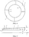
- FIGS. 1 to 5 show an embodiment of a burner cap for gas stoves, which comprises a substantially annular cap body 1, on the underside of a concave gas receiving space 2 is formed.
- a burner cap for gas stoves which comprises a substantially annular cap body 1, on the underside of a concave gas receiving space 2 is formed.
- the four projections 3 which are hollow, wherein the cavity is directly in communication with the gas receiving space 2.
- the four projections 3 continuously increase along the circumference of the cap body 1 in the same direction, ie the Anformung 3 has a thickness or height which increases uniformly, or the top surface 6 of the Anformung 3 extends substantially at a predetermined angle obliquely up.
- a front end face 7 is formed, which is enclosed by an inner side surface 4 of the Anformung, an outer side surface 5 of the Anformung and the upper side surface 6 of the Anformung 3.
- the front end face 7 is radially aligned, i. the front end surface 7 and the upper side of the cap body 1 intersect in a straight line passing through the center of a circle described by the outer edge of the top of the cap body 1. It should be noted that due to the annular configuration of the cap body 1, each of the outer and inner edges of the top of the cap body 1 described circles are arranged concentrically to each other.
- the Anformung 3 is provided on its inner side surface 4 with inner combustion or gas outlets 8 for generating internal flames and on its outer side surface 5 with outer burners or Gasausströmö réelleen 9 for generating external flames.
- located on the outside of the side wall of the cap body 1 according to at least one circumferential Flammenübertragungsnut 12 Fig. 2 and Fig. 5 while on the inside of the side wall of the cap body 1 at least one ring of gas pipe holes 13 according to Fig. 3 is formed, wherein the circumferential Flammenübertragungsnut 12 is connected via the gas line holes 13 with the gas receiving space 2.
- the gas receiving space 2 is in Connection with a gas mixing chamber of the burner holder and serves to receive and forward the fuel gas in the circumferential Flammenübertragungsnut 12 and in the cavity of Anformung 3, wherein the fuel gas respectively from the inner combustion 8, outer burners 9, central burners 10 and from the circulating Flammenübertragungsnut 12th exit to be inflamed.
- the four formations 3 are formed with respect to their structure, the shape and size the same and are distributed uniformly along the circumferential direction of the cap body 1. From the aesthetic point of view, the four formations 3 as a whole form a spiral-shaped structure.
- the individual inner firing points 8 are in each case displaced upward in accordance with the increase in the height of the respective molding 3 but are arranged at a constant distance from the upper surface of the molding 3. The same applies to the outer burners 9.
- the inner combustion stations 8 are arranged at an equal distance from the upper side surface of the respective Anformung 3 as the outer burners 9 to the top surface of the respective Anformung 3. It follows that the inner burners 8 and the outer Burning 9 at the four projections 3 also form a total of a spiral-shaped structure.
- the adjacent inner firing points 8 of an Anformung 3 the same distance from each other. This is also the case with the outer combustion point 9. This ensures a uniform flame distribution.
- the individual inner and outer burners 8, 9 are shifted upward in accordance with the increase in the height of the respective Anformung 3, so that neither the adjacent inner burners 8 nor the adjacent outer burners 9 Anformung 3 in a plane lie. It is understood that in a distance measurement of the straight line distance between the centers of each two adjacent burners to be determined.
- the cap body 1 and the projections 3 are integrally formed, ie they are, for example, fused together at their joint.
- the front end surface 7, the outer side surface 5 and the inner side surface 4 of the Anformung 3 are inclined towards the inside of the Anformung 3, whereby on the one hand a larger area and thus a higher number of burners and a better firing efficiency can be achieved, and saved on the other material becomes.
- the outer side surface 5 of the Anformung 3 with an horizontal plane preferably closes an angle ⁇ with 45 ° ⁇ ⁇ ⁇ 90 °, where ⁇ is particularly preferably 70 °.
- the inner side surface 4 of the Anformung 3 with the horizontal plane an angle ⁇ preferably at 30 ° ⁇ ⁇ ⁇ 60 °, wherein ⁇ is particularly preferably 45 °.
- the front end face 7 of the Anformung 3 with the horizontal plane an angle ⁇ preferably with 30 ° ⁇ ⁇ ⁇ 80 °, particularly preferably with 55 ° ⁇ ⁇ ⁇ 60 °.
- the outer side surface 5 of the Anformung 3 borders with its underside on the outer edge of the top of the cap body 1 and the inner side surface 4 of the Anformung 3 with its underside to the inner edge of the top of the cap body 1.
- a rear end face is formed, which is enclosed by the inner side surface 4, the outer side surface 5 and the upper side surface 6 of the Anformung 3 and lower at its upper side than the lower edge of the central burners 10 on the front end face 7 of an adjacent Anformung 3 is arranged. In this way, a trouble-free outflow of the fuel gas from the central burners 10 can be ensured.
- Adjacent moldings 3 are arranged head to toe, i.
- the inner end 8 is perpendicular to the inner side surface of the Anformung 3, the outer focal point 9 perpendicular to the outer side surface of the Anformung 3 and the central combustion 10th aligned perpendicular to the front end face 7.
- the cap body 1 has a height h1 of 5 mm to 20 mm, preferably 10 mm, and the Anformung 3 a height h2 of 2 mm to 10 mm, preferably 5 mm. Experiments have shown that the height described can lead to optimal combustion performance of the burner cap.
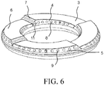
- Fig. 6 shows a further embodiment of a burner cap for gas stoves, which differs from the previously illustrated embodiment in that instead of the central burners 10 in the front end face 7, a groove or recess 11 is formed, which is connected to the cavity of the Anformung 3.
- the recess 11 is used to create a central flame in the combustion process, which should connect the inner flames with the outer flames.
- the recess 11 can additionally serve as a flame transmission groove.
- a rear end face is formed, which is enclosed by the inner side surface 4, the outer side surface 5 and the upper side surface 6 of the Anformung 3 and lower at its top than the lower edge of the recess 11 on the front end face 7 of an adjacent Anformung 3 is arranged. In this way, a trouble-free outflow of the fuel gas from the recess 11 can be sure.
- the present invention further includes an embodiment of a burner for gas stoves, comprising a burner socket with a gas mixing chamber, a burner cap adapted to the burner socket according to one of the embodiments presented above, and a smaller central burner cap.
- the burner cap and the burner holder are matched to each other so that the gas receiving space 2 of the burner cap is in communication with the gas mixing chamber of the burner holder to receive fuel gas from the gas mixing chamber.
- the present invention comprises a gas stove which has a base, pipelines, valves, a cover plate, pot carrier, control electronics and at least one burner with a burner cap according to one of the exemplary embodiments presented above.
Description
Die vorliegende Erfindung betrifft eine Brennerkappe, einen Brenner und einen Gasherd.The present invention relates to a burner cap, a burner and a gas stove.
Bei herkömmlichen Brennern für Gasherde sind zwischen den äußeren und inneren Brennstellen einer ringförmigen Brennerkappe keine weiteren Brennstellen vorhanden. Wenn ein Kochgeschirr zum Erwärmen auf den Brenner gestellt wird, weisen die Bereiche ohne direkten Kontakt zur Flamme eine niedrige Temperatur auf, während die Bereiche der Topfunterseite, welche unmittelbar mit den äußeren und inneren Brennstellen in Kontakt stehen und dadurch erhitzt werden, eine erheblich höhere Temperatur aufweisen. Durch einen Brenner mit einer derartigen Brennerkappe wird also die Topfunterseite sehr ungleichmäßig erwärmt. Dies führt zu einem größeren Zeitaufwand beim Kochen, einem höherem Gasverbrauch und zu einer geringeren Heizleistung. Auch eine Beeinträchtigung des Geschmacks ist möglich.In conventional burners for gas stoves, no further burners are present between the outer and inner burners of an annular burner cap. When a cookware is put on the burner for heating, the areas without direct contact with the flame have a low temperature, while the areas of the bottom of the pot, which are in direct contact with the outer and inner burners and are heated thereby, a considerably higher temperature respectively. By a burner with such a burner cap so the bottom of the pot is heated very unevenly. This leads to a greater amount of time when cooking, a higher gas consumption and lower heating power. A deterioration of the taste is possible.
In dem Dokument
Die
Eine Aufgabe der vorliegenden Erfindung besteht darin, eine Brennerkappe für Gasherde bereitzustellen, mit der die Verteilung der Brennstellen verbessert und die Heizleistung erhöht werden können.An object of the present invention is to provide a burner cap for gas stoves, with which the distribution of the burners can be improved and the heating power can be increased.
Eine weitere Aufgabe der vorliegenden Erfindung ist es, einen Brenner mit einer Brennerkappe für Gasherde vorzuschlagen, mit der die Verteilung der Brennstellen verbessert und die Heizleistung erhöht werden können.Another object of the present invention is to propose a burner with a burner cap for gas stoves, with which the distribution of the burners improved and the heating power can be increased.
Eine weitere Aufgabe der vorliegenden Erfindung ist es, einen Gasherd mit einer Brennerkappe für Gasherde vorzuschlagen, mit der die Verteilung der Brennstellen verbessert und die Heizleistung erhöht werden können.Another object of the present invention is to propose a gas range with a burner cap for gas stoves, with which the distribution of the burners can be improved and the heat output can be increased.
Demgemäß wird eine Brennerkappe für Gasherde vorgesehen, die einen ringförmigen Kappenkörper umfasst, an dessen Unterseite ein - vorzugsweise konkaver - Gasaufnahmeraum ausgebildet ist. An der Oberseite des Kappenkörpers befinden sich zumindest zwei Anformungen, die hohl ausgeführt sind, wobei der Hohlraum - vorzugsweise direkt - mit dem Gasaufnahmeraum in Verbindung steht. Dabei erhöhen sich die Anformungen kontinuierlich entlang des Umfangs des Kappenkörpers in gleicher Richtung. An dem höher liegenden Ende der Anformung ist eine vordere Stirnfläche ausgebildet, die von einer Innenseitenfläche, einer Außenseitenfläche und einer Oberseitenfläche der Anformung umschlossen ist. An der Innen- und Außenseitenfläche der Anformung sind jeweils innere bzw. äußere Brennstellen ausgebildet.Accordingly, a burner cap for gas stoves is provided which comprises an annular cap body, on the underside of a - preferably concave - gas receiving space is formed. At the top of the cap body there are at least two projections, which are hollow, wherein the cavity - preferably directly - is in communication with the gas receiving space. In this case, the projections continuously increase along the circumference of the cap body in the same direction. At the higher end of the Anformung a front end surface is formed, which is enclosed by an inner side surface, an outer side surface and a top surface of the Anformung. On the inner and outer side surface of the Anformung each inner or outer burners are formed.
Die einzelnen Anformungen sind vorzugsweise bezüglich Aufbau, Form und Größe gleich oder identisch ausgebildet und entlang der Umfangsrichtung des Kappenkörpers gleichmäßig verteilt. Die einzelnen inneren und äußeren Brennstellen sind vorzugsweise entsprechend der Zunahme der Höhe der jeweiligen Anformung nach oben verschoben, aber in einem konstanten Abstand zur Oberseitenfläche der Anformung angeordnet. Darüber hinaus weisen benachbarte innere Brennstellen einer Anformung und benachbarte äußeren Brennstellen einer Anformung jeweils den gleichen Abstand zueinander auf.The individual formations are preferably the same or identical in construction, shape and size and distributed uniformly along the circumferential direction of the cap body. The individual inner and outer firing points are preferably displaced upwardly in accordance with the increase in the height of the respective Anformung, but arranged at a constant distance from the upper surface of the Anformung. In addition, adjacent inner firing points of a molding and adjacent outer firing points of a molding each have the same distance from each other.
Bevorzugt ist dabei vorgesehen, dass an der vorderen Stirnfläche mittige Brennstellen und/oder eine Ausnehmung ausgebildet sind/ist, wobei die Ausnehmung mit dem Hohlraum der jeweiligen Anformung verbunden ist.It is preferably provided that on the front end face central burners and / or a recess are formed / is, wherein the recess is connected to the cavity of the respective Anformung.
Der Kappenkörper und die Anformung sind vorzugsweise einteilig, insbesondere materialeinstückig, ausgeführt. Der Kappenkörper und die Anformung können ein einziges Bauteil sein.The cap body and the Anformung are preferably in one piece, in particular materialeinstückig executed. The cap body and the Anformung can be a single component.
Vorzugsweise schließt die Oberseitenfläche der Anformung mit der Horizontalebene einen Winkel θ mit 5° ≤ θ ≤ 30° ein. Der Winkel θ beträgt vorzugsweise 15°.Preferably, the top surface of the molding with the horizontal plane includes an angle θ with 5 ° ≤ θ ≤ 30 °. The angle θ is preferably 15 °.
Die Anzahl der Anformungen beträgt vorzugsweise zwei bis acht. Die Anzahl der Anformungen beträgt besonders bevorzugt drei oder vier.The number of projections is preferably two to eight. The number of projections is particularly preferably three or four.
Die vordere Stirnfläche ist bevorzugt radial ausgerichtet.The front end face is preferably aligned radially.
Vorzugsweise ist die vordere Stirnfläche oder die Außenseitenfläche oder die Innenseitenfläche der Anformung zur Innenseite der Anformung hin schräggestellt.Preferably, the front end surface or the outer side surface or the inner side surface of the Anformung is tilted toward the inside of the Anformung.
Vorzugsweise schließt die Außenseitenfläche der Anformung mit der Horizontalebene einen Winkel γ mit 45° ≤ γ ≤ 90° ein.Preferably, the outer side surface of the Anformung with the horizontal plane includes an angle γ with 45 ° ≤ γ ≤ 90 °.
Vorzugsweise schließt die Innenseitenfläche der Anformung mit der Horizontalebene einen Winkel δ mit 30° ≤ δ ≤ 60° ein.Preferably, the inner side surface of the Anformung forms with the horizontal plane an angle δ with 30 ° ≤ δ ≤ 60 °.
Vorzugsweise schließt die vordere Stirnfläche der Anformung mit der Horizontalebene einen Winkel β mit 30° ≤ β ≤ 80° ein.Preferably, the front end face of the Anformung with the horizontal plane forms an angle β with 30 ° ≤ β ≤ 80 °.
Die Außen- und Innenseitenflächen der Anformung grenzen bevorzugt mit ihrer Unterseite jeweils an die Außen- bzw. Innenkante der Oberseite des Kappenkörpers.The outer and inner side surfaces of the Anformung delimited preferably with its underside in each case to the outer or inner edge of the top of the cap body.
Am tiefer liegenden Ende der Anformung geht diese bevorzugt in die Oberseite des Kappenkörpers in eine Ebene über.At the lower end of the Anformung this is preferably in the top of the cap body in a plane over.
Vorzugsweise ist am tiefer liegenden Ende der Anformung eine hintere Stirnfläche ausgebildet, die von der Innenseitenfläche, der Außenseitenfläche und der Oberseitenfläche der Anformung begrenzt ist und an ihrer Oberseite tiefer als der Unterrand der mittigen Brennstellen oder der Ausnehmung an der vorderen Stirnfläche einer benachbarten Anformung angeordnet ist.Preferably, at the lower end of the Anformung a rear end surface is formed, which is bounded by the inner side surface, the outer side surface and the upper surface of the Anformung and lower at its top than the lower edge of the central Burning points or the recess is arranged on the front end face of an adjacent Anformung.
Benachbarte Anformungen sind vorzugsweise Kopf an Fuß angeordnet, wobei die jeweils hintere Stirnfläche einer vorderen Anformung mit der Unterseite an die vordere Stirnfläche einer benachbarten hinteren Anformung grenzt.Adjacent moldings are preferably arranged head to toe, the respective rear end face of a front molding with the underside being adjacent to the front end face of an adjacent rear molding.
Benachbarte Anformungen sind bevorzugt voneinander beabstandet angeordnet, wobei zwischen der Oberseite des Kappenkörpers und den benachbarten Anformungen ein Luftzufuhrkanal ausgebildet ist.Adjacent moldings are preferably arranged at a distance from one another, wherein an air supply duct is formed between the upper side of the cap body and the adjacent moldings.
Es ist bevorzugt vorgesehen, dass die inneren Brennstellen senkrecht zur Innenseitenfläche der Anformung, die äußere Brennstelle senkrecht zur Außenseitenfläche der Anformung und die mittige Brennstelle oder die Ausnehmung senkrecht zur vorderen Stirnfläche ausgerichtet sind.It is preferably provided that the inner combustion points are aligned perpendicular to the inner side surface of the Anformung, the outer focal point perpendicular to the outer side surface of the Anformung and the central firing point or the recess perpendicular to the front end face.
Vorzugsweise weist der Kappenkörper eine Dicke bzw. Höhe von 5 mm bis 20 mm und die Anformung eine Dicke bzw. Höhe von 2 mm bis 10 mm auf.Preferably, the cap body has a thickness or height of 5 mm to 20 mm and the Anformung a thickness or height of 2 mm to 10 mm.
An der Seitenwand des Kappenkörpers befindet sich vorzugsweise mindestens eine umlaufende Flammenübertragungsnut.On the side wall of the cap body is preferably at least one circumferential Flammenübertragungsnut.
Die Aufgabe wird weiterhin durch einen Brenner für Gasherde gelöst, der eine Brennerhülse mit einem Gasmischraum, eine auf die Brennerhülse abgestimmte und wie oben beschrieben ausgeführte ringförmige Brennerkappe und eine kleinere zentrale Brennerkappe umfasst.The object is further achieved by a burner for gas stoves, comprising a burner sleeve with a gas mixing chamber, an adapted to the burner sleeve and as described above executed annular burner cap and a smaller central burner cap.
Die Aufgabe wird schließlich durch einen Gasherd gelöst, der einen Unterbau, Rohrleitungen, Ventile, eine Deckplatte, einen Topfträger, eine Steuerungselektronik und einen oben beschriebenen Brenner umfasst.The object is finally achieved by a gas stove comprising a base, piping, valves, a cover plate, a pot carrier, an electronic control system and a burner described above.
Die vorliegende Erfindung bietet insbesondere folgende Vorteile:
- Das Vorsehen der mittigen Brennstellen oder der Ausnehmung erlaubt eine gleichmäßigere Verteilung der Brennstellen insgesamt. Hinzu kommt, dass die einzelnen inneren und äußeren Brennstellen entsprechend der Zunahme der Höhe der jeweiligen Anformung nach oben verschoben sind, was eine spiralförmige Flammenverteilung bewirken kann. Dadurch wird eine ungleichmäßige Wärmeverteilung durch die inhomogene Erwärmung der Topfunterseite verhindert, die Kochqualität sowie die Nutzleistung des Brenngases erhöht und dem Benutzer Kochzeit eingespart. Versuche haben gezeigt, dass mit den erfindungsgemäßen Ausgestaltungen die Heizleistung gegenüber herkömmlichen Brennerkappen um 2% bis 3% erhöht wird, wodurch Energie eingespart wird.
- Mit den vorgeschlagenen konstruktiven Ausgestaltungen kann die Brennerkappe eine geringere Durchschnittsdicke und eine kleinere Baugröße aufweisen, wodurch Material eingespart wird und die Herstellungskosten reduziert werden.
- Dadurch, dass sich die Anformungen entlang des Umfangs des Kappenkörpers kontinuierlich erhöhen, kann im Verbrennungsvorgang eine bessere Ergänzung von Sekundärluft und somit eine vollständige Verbrennung und höhere Heizleistung erzielt werden.
- The provision of the central burners or the recess allows a more even distribution of the burners as a whole. In addition, the individual inner and outer firing positions are shifted upward in accordance with the increase in the height of the respective molding, which may cause a spiral flame distribution. As a result, an uneven heat distribution is prevented by the inhomogeneous heating of the bottom of the pot, the cooking quality and the useful power of the fuel gas increases and saves the user cooking time. Experiments have shown that with the embodiments according to the invention, the heating power compared to conventional burner caps is increased by 2% to 3%, whereby energy is saved.
- With the proposed structural configurations, the burner cap may have a smaller average thickness and smaller size, thereby saving material and reducing manufacturing costs.
- Characterized in that the projections increase continuously along the circumference of the cap body, a better complement of secondary air and thus a complete combustion and higher heat output can be achieved in the combustion process.
Zum besseren Verständnis der Aufgabe, der Ausgestaltungen und Vorteile der vorliegenden Erfindung wird diese nachfolgend mit Hilfe der beigefügten Zeichnungen und bevorzugten Ausführungsbeispiele näher erläutert. Dabei zeigen
- Fig. 1
- eine perspektivische Darstellung eines Ausführungsbeispiels einer Brennerkappe für Gasherde,
- Fig. 2
- eine Seitenansicht des Ausführungsbeispiels einer Brennerkappe für Gasherde,
- Fig. 3
- eine Unteransicht des Ausführungsbeispiels einer Brennerkappe für Gasherde,
- Fig. 4
- eine Draufsicht des Ausführungsbeispiels einer Brennerkappe für Gasherde,
- Fig. 5
- eine Teilansicht des Ausführungsbeispiels einer Brennerkappe für Gasherde und
- Fig. 6
- eine perspektivische Darstellung eines weiteren Ausführungsbeispiels einer Brennerkappe für Gasherde.
- Fig. 1
- a perspective view of an embodiment of a burner cap for gas stoves,
- Fig. 2
- a side view of the embodiment of a burner cap for gas stoves,
- Fig. 3
- a bottom view of the embodiment of a burner cap for gas stoves,
- Fig. 4
- a top view of the embodiment of a burner cap for gas stoves,
- Fig. 5
- a partial view of the embodiment of a burner cap for gas stoves and
- Fig. 6
- a perspective view of another embodiment of a burner cap for gas stoves.
Die
Am höher liegenden Ende der Anformung 3 ist eine vordere Stirnfläche 7 ausgebildet, die von einer Innenseitenfläche 4 der Anformung, einer Außenseitenfläche 5 der Anformung und der Oberseitenfläche 6 der Anformung 3 umschlossen ist. Die vordere Stirnfläche 7 ist radial ausgerichtet, d.h. die vordere Stirnfläche 7 und die Oberseite des Kappenkörpers 1 schneiden sich in einer Geraden, die durch den Mittelpunkt eines von der Außenkante der Oberseite des Kappenkörpers 1 beschriebenen Kreises läuft. Es sei darauf hingewiesen, dass aufgrund der ringförmigen Ausgestaltung des Kappenkörpers 1 die jeweils von den Außen- und Innenkanten der Oberseite des Kappenkörpers 1 beschriebenen Kreise konzentrisch zueinander angeordnet sind.At the higher end of the
Die Anformung 3 ist an ihrer Innenseitenfläche 4 mit inneren Brennstellen bzw. Gasausströmöffnungen 8 zur Erzeugung von inneren Flammen und an ihrer Außenseitenfläche 5 mit äußeren Brennstellen bzw. Gasausströmöffnungen 9 zur Erzeugung von äußeren Flammen versehen. Zudem befindet sich an der Außenseite der Seitenwand des Kappenkörpers 1 zumindest eine umlaufende Flammenübertragungsnut 12 gemäß
Die vier Anformungen 3 sind bezüglich ihres Aufbaus, der Form und Größe gleich ausgebildet und sind entlang der Umfangsrichtung des Kappenkörpers 1 gleichmäßig verteilt. Vom ästhetischen Aspekt her, bilden die vier Anformungen 3 insgesamt eine spiralförmige Struktur. Die einzelnen inneren Brennstellen 8 sind entsprechend der Zunahme der Höhe der jeweiligen Anformung 3 jeweils nach oben verschoben aber in einem konstanten Abstand zur Oberseitenfläche der Anformung 3 angeordnet. Gleiches gilt für die äußeren Brennstellen 9. Überdies sind die inneren Brennstellen 8 in einem gleichen Abstand zur Oberseitenfläche der jeweiligen Anformung 3 angeordnet wie die äußeren Brennstellen 9 zur Oberseitenfläche der jeweiligen Anformung 3. Daraus ergibt sich, dass die inneren Brennstellen 8 und auch die äußeren Brennstellen 9 an den vier Anformungen 3 insgesamt ebenfalls eine spiralförmige Struktur ausbilden. Zusätzlich dazu weisen die benachbarten inneren Brennstellen 8 einer Anformung 3 den gleichen Abstand zueinander auf. So verhält es sich auch bei der äußeren Brennstelle 9. Dadurch wird eine gleichmäßige Flammenverteilung gewährleistet. Es sei nochmals darauf hingewiesen, dass die einzelnen inneren und äußeren Brennstellen 8, 9 entsprechend der Zunahme der Höhe der jeweiligen Anformung 3 nach oben verschoben sind, so dass weder die benachbarten inneren Brennstellen 8 noch die benachbarten äußeren Brennstellen 9 einer Anformung 3 in einer Ebene liegen. Es wird verstanden, dass bei einer Abstandmessung der geradlinige Abstand zwischen den Mittelpunkten je zweier benachbarter Brennstellen ermittelt werden soll.The four
Der Kappenkörper 1 und die Anformungen 3 sind einteilig ausgebildet, d.h. sie sind beispielsweise an ihrer Fügestelle miteinander verschmolzen. Außerdem sind die vordere Stirnfläche 7, die Außenseitenfläche 5 und die Innenseitenfläche 4 der Anformung 3 zur Innenseite der Anformung 3 hin schräg gestellt, wodurch zum einen eine größere Fläche und damit eine höhere Brennstellenanzahl und ein besserer Feuerungswirkungsgrad erzielt werden kann, und zum anderen Material eingespart wird. Ferner schließt die Außenseitenfläche 5 der Anformung 3 mit einer Horizontalebene einen Winkel γ vorzugsweise mit 45° ≤ γ ≤ 90° ein, wobei γ besonders bevorzugt 70° beträgt. Weiterhin schließt die Innenseitenfläche 4 der Anformung 3 mit der Horizontalebene einen Winkel δ vorzugsweise mit 30° ≤ δ ≤ 60° ein, wobei δ besonders bevorzugt 45° beträgt. Schließlich schließt die vordere Stirnfläche 7 der Anformung 3 mit der Horizontalebene einen Winkel β vorzugsweise mit 30° ≤ β ≤ 80°, besonders bevorzugt mit 55° ≤ β ≤ 60° ein. Bisherige Versuche haben gezeigt, dass die beschriebene Winkelgröße zu einer optimalen Verbrennungsleistung der Brennerkappe führen kann.The
Die Außenseitenfläche 5 der Anformung 3 grenzt mit ihrer Unterseite an die Außenkante der Oberseite des Kappenkörpers 1 und die Innenseitenfläche 4 der Anformung 3 mit ihrer Unterseite an die Innenkante der Oberseite des Kappenkörpers 1. Am tiefer liegenden Ende der Anformung 3 ist eine hintere Stirnfläche ausgebildet, die von der Innenseitenfläche 4, der Außenseitenfläche 5 und der Oberseitenfläche 6 der Anformung 3 umschlossen ist und an ihrer Oberseite tiefer als der Unterrand der mittigen Brennstellen 10 an der vorderen Stirnfläche 7 einer benachbarten Anformung 3 angeordnet ist. Auf diese Weise lässt sich eine störungsfreie Ausströmung des Brenngases aus den mittigen Brennstellen 10 sicherstellen.The
Benachbarte Anformungen 3 sind Kopf an Fuß angeordnet, d.h. die jeweils hintere Stirnfläche einer vorderen Anformung 3 grenzt mit der Unterseite an die vordere Stirnfläche 7 einer benachbarten hinteren Anformung 3. Die innere Brennstelle 8 ist senkrecht zur Innenseitenfläche der Anformung 3, die äußere Brennstelle 9 senkrecht zur Außenseitenfläche der Anformung 3 und die mittige Brennstelle 10 senkrecht zur vorderen Stirnfläche 7 ausgerichtet.
Wie der
Ausgehend von den obigen Ausführungsbeispielen können durch Austausch und/oder Weiterbildung der einzelnen Merkmale weitere Ausführungsformen erhalten werden. So kann z.B. das tiefer liegende Ende der Anformung 3 keine hintere Stirnfläche bilden, sondern mit der Oberseite des Kappenkörpers 1 in eine Ebene übergehen. Ferner ist es beispielsweise denkbar, dass benachbarte Anformungen 3 nicht direkt Kopf an Fuß, sondern voneinander beabstandet angeordnet sind, wobei aus einer hinteren Stirnfläche bzw. dem hinteren Ende der jeweils vorderen Anformung 3, der vorderen Stirnfläche 7 einer hinteren Anformung 3 und der Oberseite des Kappenkörpers 1 ein Luftzufuhrkanal ausgebildet ist, um Sekundärluft für den Verbrennungsvorgang zu ergänzen. Schließlich kann auch vorgesehen sein, dass die vordere Stirnfläche 7 nicht radial, sondern in einem bestimmten Winkel abweichend von der Radialrichtung ausgerichtet ist. Dabei können die jeweiligen vier vorderen Stirnflächen 7 gleichsinnig ausgerichtet sein, um eine Symmetrie des Gesamtaufbaus aufrechtzuerhalten.Starting from the above exemplary embodiments, further embodiments can be obtained by exchanging and / or developing the individual features. Thus, e.g. the lower end of the
Die vorliegende Erfindung umfasst ferner ein Ausführungsbeispiel eines Brenners für Gasherde, der eine Brennerfassung bzw. eine Brennerhülse mit einem Gasmischraum, eine auf die Brennerfassung abgestimmte Brennerkappe gemäß einem der oben dargestellten Ausführungsbeispiele und eine kleinere zentralen Brennerkappe umfasst. Die Brennerkappe und die Brennerfassung sind aufeinander so abgestimmt, dass der Gasaufnahmeraum 2 der Brennerkappe in Verbindung mit dem Gasmischraum der Brennerfassung steht, um Brenngas aus dem Gasmischraum zu empfangen.The present invention further includes an embodiment of a burner for gas stoves, comprising a burner socket with a gas mixing chamber, a burner cap adapted to the burner socket according to one of the embodiments presented above, and a smaller central burner cap. The burner cap and the burner holder are matched to each other so that the gas receiving space 2 of the burner cap is in communication with the gas mixing chamber of the burner holder to receive fuel gas from the gas mixing chamber.
Die vorliegende Erfindung umfasst schließlich einen Gasherd, der einen Unterbau, Rohrleitungen, Ventile, eine Deckplatte, Topfträger, eine Steuerungselektronik und mindestens einen Brenner mit einer Brennerkappe gemäß einem der oben dargestellten Ausführungsbeispiele aufweist.Finally, the present invention comprises a gas stove which has a base, pipelines, valves, a cover plate, pot carrier, control electronics and at least one burner with a burner cap according to one of the exemplary embodiments presented above.
Das zuvor Beschriebene betrifft lediglich bevorzugte Ausführungsformen der vorliegenden Erfindung dar. Dazu sei anzumerken, dass die vorliegende Erfindung nicht nur auf die oben beschriebenen Ausführungsformen beschränkt ist, sondern weitere mögliche Ausführungen umfasst, die durch die Patentansprüche in Zusammenhang mit der Offenbarung in der Beschreibung definiert werden.The above-described concerns only preferred embodiments of the present invention. It should be noted that the present invention is not limited only to the embodiments described above, but includes other possible embodiments defined by the claims in conjunction with the disclosure in the specification ,
- 11
- Kappenkörpercap body
- 22
- GasaufnahmeraumGas receiving chamber
- 33
- Anformungconformation
- 44
- Innenseitenfläche der AnformungInner side surface of the Anformung
- 55
- Außenseitenfläche der AnformungOuter side surface of the Anformung
- 66
- Oberseitenfläche der AnformungTop surface of the molding
- 77
- Vordere StirnflächeFront face
- 88th
- Innere BrennstelleInternal combustion
- 99
- Äußere BrennstelleOuter focal point
- 1010
- Mittige BrennstelleCentral firing point
- 1111
- Ausnehmungrecess
- 1212
- Umlaufende FlammenübertragungsnutCircumferential flame transmission groove
Claims (15)
- Burner cap for a gas range, comprising an annular cap body (1), on the lower side of which is formed a gas receiving space (2) and on the upper side of which at least two hollow mouldings (3) are arranged, wherein a respective cavity of a moulding (3) is connected to the gas receiving space (2) and the mouldings (3) continuously increase in height along the circumference of the cap body (1) in the same direction, wherein at a higher end of the moulding (3) a front end face (7) is formed, which is bounded by an interior surface (4), an exterior surface (5) and a top surface (6) of the moulding (3), and wherein interior combustion points (8) are in each case formed on the interior surface (4) of the moulding (3), characterised in that exterior combustion points (9) are in each case formed on the exterior surface (5) of the moulding (3).
- Burner cap according to claim 1, characterised in that the individual mouldings (3) are identically formed and are distributed evenly along the circumferential direction of the cap body (1).
- Burner cap according to claim 1 or 2, characterised in that the interior (8) and exterior combustion points (9) are displaced upwards in accordance with the increase in height of the respective moulding (3) and are arranged at a constant spacing from the top surface (6) of the moulding (3), such that the adjacent interior combustion points (8) of a moulding have an equal spacing from one another, and that adjacent exterior combustion points (8) of a moulding have an equal spacing from one another.
- Burner cap according to one of claims 1 - 3, characterised in that central combustion points (10) are formed on the front end face (7).
- Burner cap according to one of claims 1 - 3, characterised in that a recess (11) is formed on the front end face (7), said recess (11) being connected to the cavity of the respective moulding (3) and connecting the interior surface (4) to the exterior surface (5).
- Burner cap according to one of claims 1 - 5, characterised in that the cap body (1) and the moulding (3) are embodied as a single piece.
- Burner cap according to one of claims 1 - 6, characterised in that the front end face (7) is radially aligned.
- Burner cap according to one of claims 1 - 7, characterised in that the front end face (7), the exterior surface (5) and/or the interior surface (4) of the moulding (3) is inclined towards the inside of the moulding (3).
- Burner cap according to one of claims 1 - 8, characterised in that the undersides of the exterior (5) and interior surfaces (4) of the moulding (3) merge respectively into the exterior and interior edge of the top surface of the cap body (1).
- Burner cap according to one of claims 1 - 9, characterised in that the lower end of the moulding (3) merges into the top surface of the cap body (1) to form a plane.
- Burner cap according to one of claims 1 - 9, characterised in that at the lower end of the moulding (3) a rear end face is formed, which is bounded by the interior surface (4), the exterior surface (5) and the top surface (6) of the moulding (3) and at its top surface is arranged lower than the lower edge of the central combustion points (10) or the recess (11) on the front end face (7) of an adjacent moulding (3).
- Burner cap according to one of claims 1 - 9 or 11, characterised in that adjacent mouldings (3) are arranged end to end such that the lower side of a rear end face of a front moulding (3) abuts a front end face (7) of an adjacent rear moulding (3).
- Burner cap according to one of claims 1 - 11, characterised in that adjacent mouldings (3) are arranged spaced apart from one another and an air supply duct is formed in the top surface of the cap body (1) between the adjacent mouldings (3).
- Burner for a gas range having a burner sleeve with a gas mixing chamber, an annular burner cap according to one of claims 1 - 13 which is aligned to the burner sleeve, and a further central burner cap.
- Gas range with a substructure, pipelines, valves, a cover plate, a pan support, control electronics and a burner according to claim 14.
Applications Claiming Priority (1)
| Application Number | Priority Date | Filing Date | Title |
|---|---|---|---|
| CN201010202881.7A CN102287822B (en) | 2010-06-18 | 2010-06-18 | Flame cover for gas range, with the burner of this kind of fire cover and gas-cooker |
Publications (3)
| Publication Number | Publication Date |
|---|---|
| EP2397757A2 EP2397757A2 (en) | 2011-12-21 |
| EP2397757A3 EP2397757A3 (en) | 2017-11-15 |
| EP2397757B1 true EP2397757B1 (en) | 2019-09-11 |
Family
ID=44645328
Family Applications (1)
| Application Number | Title | Priority Date | Filing Date |
|---|---|---|---|
| EP11168944.4A Active EP2397757B1 (en) | 2010-06-18 | 2011-06-07 | Burner cap for gas range and burner with same |
Country Status (2)
| Country | Link |
|---|---|
| EP (1) | EP2397757B1 (en) |
| CN (1) | CN102287822B (en) |
Families Citing this family (7)
| Publication number | Priority date | Publication date | Assignee | Title |
|---|---|---|---|---|
| CN103900086B (en) * | 2014-03-26 | 2015-12-30 | 宁波安佳卫厨电器有限公司 | The fiery groove burner with high efficiency of a kind of concealed biography |
| CN104456558B (en) * | 2014-11-28 | 2017-03-15 | 珠海格力电器股份有限公司 | Burner and the gas-cooker with which |
| CN104748117A (en) * | 2015-02-12 | 2015-07-01 | 上海林内有限公司 | Petal type big flame cover and combustor provided with same |
| CN106895405B (en) * | 2015-12-18 | 2020-07-14 | 博西华电器(江苏)有限公司 | Fire cover of gas burner, gas burner and gas stove |
| CN106152132B (en) * | 2016-08-03 | 2018-10-02 | 宁波方太厨具有限公司 | Cooker burner |
| CN110388645A (en) * | 2018-04-16 | 2019-10-29 | 宁波方太厨具有限公司 | A kind of gas burner fire cover |
| CN109556154B (en) * | 2018-12-18 | 2023-12-29 | 成都前锋电子有限责任公司 | Kitchen range convenient to clean, easy to adjust and high in combustion efficiency |
Family Cites Families (8)
| Publication number | Priority date | Publication date | Assignee | Title |
|---|---|---|---|---|
| US5842849A (en) * | 1997-09-05 | 1998-12-01 | Huang; Hsu-Sheng | Gas burner |
| ITVE20050004A1 (en) * | 2005-01-20 | 2006-07-21 | Ohg Defendi S R L | GAS BURNER FOR COOKING EQUIPMENT. |
| JP3812585B2 (en) * | 2005-03-18 | 2006-08-23 | 松下電器産業株式会社 | Stove burner |
| CN2859238Y (en) * | 2005-10-28 | 2007-01-17 | 廖珈 | Fire cover for gas kitchen range |
| US7628609B2 (en) * | 2006-12-29 | 2009-12-08 | Electrolux Home Products, Inc. | Hub and spoke burner with flame stability |
| CN201129728Y (en) * | 2007-09-25 | 2008-10-08 | 明协华 | Fire divider |
| CN201209862Y (en) * | 2008-01-23 | 2009-03-18 | 周建基 | Fire cap with sanitation flame transmission belt |
| CN101737782B (en) * | 2008-11-21 | 2012-08-29 | 博西华电器(江苏)有限公司 | Fire cover of furnace end of gas cooker and furnace end with same |
-
2010
- 2010-06-18 CN CN201010202881.7A patent/CN102287822B/en active Active
-
2011
- 2011-06-07 EP EP11168944.4A patent/EP2397757B1/en active Active
Non-Patent Citations (1)
| Title |
|---|
| None * |
Also Published As
| Publication number | Publication date |
|---|---|
| CN102287822B (en) | 2015-11-25 |
| EP2397757A2 (en) | 2011-12-21 |
| CN102287822A (en) | 2011-12-21 |
| EP2397757A3 (en) | 2017-11-15 |
Similar Documents
| Publication | Publication Date | Title |
|---|---|---|
| EP2397757B1 (en) | Burner cap for gas range and burner with same | |
| EP2290287B1 (en) | Burner cap for gas range and burner with same | |
| EP2211095B1 (en) | Gas burner | |
| DE69908468T2 (en) | Gas burners for cooking appliances | |
| DE2051330A1 (en) | Gas burner and control for it | |
| EP3679301B1 (en) | Pan support, gas hob and method for producing a pan support | |
| DE10012578C2 (en) | hob | |
| EP3278024B1 (en) | Gas burner with burner cover | |
| EP2090826A1 (en) | Gas burner | |
| DE69830753T2 (en) | DEEP BURNING DEVICE | |
| EP2984410B1 (en) | Pan support arrangement and gas hob | |
| DE2404630A1 (en) | HEAT EXCHANGER | |
| DE3018794C2 (en) | Gas stove with a heat transferring plate and a radiant burner | |
| EP3450852B1 (en) | Gas hob and gas range | |
| DE102013218852A1 (en) | Arrangement of gas burners | |
| EP2439449B1 (en) | Gas burner for a cooking hob | |
| DE102008019572B4 (en) | Burner crown with discharge holes on different levels and alternately, in one piece, with high performance for burners of commercial kitchens for cooking food | |
| DE2107215C3 (en) | Grill plate for gas oven | |
| DE19713407A1 (en) | Atmospheric gas burner | |
| DE102014208409A1 (en) | Radiator for a cooking appliance and cooking appliance with a radiator | |
| DE102017125694B4 (en) | Burner head for in particular a gas burner | |
| DE2107215B2 (en) | GRILL PLATE FOR GAS OVEN | |
| DE102009050517B4 (en) | Burning grill kit | |
| EP3206459B1 (en) | Cooking plate and cook top with a cooking plate | |
| DE60312522T3 (en) | Hobs with a special shape |
Legal Events
| Date | Code | Title | Description |
|---|---|---|---|
| AK | Designated contracting states |
Kind code of ref document: A2 Designated state(s): AL AT BE BG CH CY CZ DE DK EE ES FI FR GB GR HR HU IE IS IT LI LT LU LV MC MK MT NL NO PL PT RO RS SE SI SK SM TR |
|
| AX | Request for extension of the european patent |
Extension state: BA ME |
|
| PUAI | Public reference made under article 153(3) epc to a published international application that has entered the european phase |
Free format text: ORIGINAL CODE: 0009012 |
|
| RIN1 | Information on inventor provided before grant (corrected) |
Inventor name: LIU, SHENCHANG Inventor name: LUO, HAITAO Inventor name: ZHANG, SHENZHOU Inventor name: MIAO, WEIWEI |
|
| RAP1 | Party data changed (applicant data changed or rights of an application transferred) |
Owner name: BSH HAUSGERAETE GMBH |
|
| PUAL | Search report despatched |
Free format text: ORIGINAL CODE: 0009013 |
|
| AK | Designated contracting states |
Kind code of ref document: A3 Designated state(s): AL AT BE BG CH CY CZ DE DK EE ES FI FR GB GR HR HU IE IS IT LI LT LU LV MC MK MT NL NO PL PT RO RS SE SI SK SM TR |
|
| AX | Request for extension of the european patent |
Extension state: BA ME |
|
| RIC1 | Information provided on ipc code assigned before grant |
Ipc: F23D 14/58 20060101ALI20171011BHEP Ipc: F23D 14/06 20060101AFI20171011BHEP |
|
| STAA | Information on the status of an ep patent application or granted ep patent |
Free format text: STATUS: REQUEST FOR EXAMINATION WAS MADE |
|
| 17P | Request for examination filed |
Effective date: 20180515 |
|
| RBV | Designated contracting states (corrected) |
Designated state(s): AL AT BE BG CH CY CZ DE DK EE ES FI FR GB GR HR HU IE IS IT LI LT LU LV MC MK MT NL NO PL PT RO RS SE SI SK SM TR |
|
| GRAP | Despatch of communication of intention to grant a patent |
Free format text: ORIGINAL CODE: EPIDOSNIGR1 |
|
| STAA | Information on the status of an ep patent application or granted ep patent |
Free format text: STATUS: GRANT OF PATENT IS INTENDED |
|
| INTG | Intention to grant announced |
Effective date: 20190417 |
|
| GRAS | Grant fee paid |
Free format text: ORIGINAL CODE: EPIDOSNIGR3 |
|
| GRAA | (expected) grant |
Free format text: ORIGINAL CODE: 0009210 |
|
| STAA | Information on the status of an ep patent application or granted ep patent |
Free format text: STATUS: THE PATENT HAS BEEN GRANTED |
|
| AK | Designated contracting states |
Kind code of ref document: B1 Designated state(s): AL AT BE BG CH CY CZ DE DK EE ES FI FR GB GR HR HU IE IS IT LI LT LU LV MC MK MT NL NO PL PT RO RS SE SI SK SM TR |
|
| REG | Reference to a national code |
Ref country code: GB Ref legal event code: FG4D Free format text: NOT ENGLISH |
|
| REG | Reference to a national code |
Ref country code: CH Ref legal event code: EP |
|
| REG | Reference to a national code |
Ref country code: AT Ref legal event code: REF Ref document number: 1178901 Country of ref document: AT Kind code of ref document: T Effective date: 20190915 |
|
| REG | Reference to a national code |
Ref country code: DE Ref legal event code: R096 Ref document number: 502011016087 Country of ref document: DE Ref country code: IE Ref legal event code: FG4D Free format text: LANGUAGE OF EP DOCUMENT: GERMAN |
|
| REG | Reference to a national code |
Ref country code: NL Ref legal event code: MP Effective date: 20190911 |
|
| REG | Reference to a national code |
Ref country code: LT Ref legal event code: MG4D |
|
| PG25 | Lapsed in a contracting state [announced via postgrant information from national office to epo] |
Ref country code: FI Free format text: LAPSE BECAUSE OF FAILURE TO SUBMIT A TRANSLATION OF THE DESCRIPTION OR TO PAY THE FEE WITHIN THE PRESCRIBED TIME-LIMIT Effective date: 20190911 Ref country code: HR Free format text: LAPSE BECAUSE OF FAILURE TO SUBMIT A TRANSLATION OF THE DESCRIPTION OR TO PAY THE FEE WITHIN THE PRESCRIBED TIME-LIMIT Effective date: 20190911 Ref country code: SE Free format text: LAPSE BECAUSE OF FAILURE TO SUBMIT A TRANSLATION OF THE DESCRIPTION OR TO PAY THE FEE WITHIN THE PRESCRIBED TIME-LIMIT Effective date: 20190911 Ref country code: BG Free format text: LAPSE BECAUSE OF FAILURE TO SUBMIT A TRANSLATION OF THE DESCRIPTION OR TO PAY THE FEE WITHIN THE PRESCRIBED TIME-LIMIT Effective date: 20191211 Ref country code: LT Free format text: LAPSE BECAUSE OF FAILURE TO SUBMIT A TRANSLATION OF THE DESCRIPTION OR TO PAY THE FEE WITHIN THE PRESCRIBED TIME-LIMIT Effective date: 20190911 Ref country code: NO Free format text: LAPSE BECAUSE OF FAILURE TO SUBMIT A TRANSLATION OF THE DESCRIPTION OR TO PAY THE FEE WITHIN THE PRESCRIBED TIME-LIMIT Effective date: 20191211 |
|
| PG25 | Lapsed in a contracting state [announced via postgrant information from national office to epo] |
Ref country code: ES Free format text: LAPSE BECAUSE OF FAILURE TO SUBMIT A TRANSLATION OF THE DESCRIPTION OR TO PAY THE FEE WITHIN THE PRESCRIBED TIME-LIMIT Effective date: 20190911 Ref country code: LV Free format text: LAPSE BECAUSE OF FAILURE TO SUBMIT A TRANSLATION OF THE DESCRIPTION OR TO PAY THE FEE WITHIN THE PRESCRIBED TIME-LIMIT Effective date: 20190911 Ref country code: AL Free format text: LAPSE BECAUSE OF FAILURE TO SUBMIT A TRANSLATION OF THE DESCRIPTION OR TO PAY THE FEE WITHIN THE PRESCRIBED TIME-LIMIT Effective date: 20190911 Ref country code: RS Free format text: LAPSE BECAUSE OF FAILURE TO SUBMIT A TRANSLATION OF THE DESCRIPTION OR TO PAY THE FEE WITHIN THE PRESCRIBED TIME-LIMIT Effective date: 20190911 Ref country code: GR Free format text: LAPSE BECAUSE OF FAILURE TO SUBMIT A TRANSLATION OF THE DESCRIPTION OR TO PAY THE FEE WITHIN THE PRESCRIBED TIME-LIMIT Effective date: 20191212 |
|
| PG25 | Lapsed in a contracting state [announced via postgrant information from national office to epo] |
Ref country code: PL Free format text: LAPSE BECAUSE OF FAILURE TO SUBMIT A TRANSLATION OF THE DESCRIPTION OR TO PAY THE FEE WITHIN THE PRESCRIBED TIME-LIMIT Effective date: 20190911 Ref country code: EE Free format text: LAPSE BECAUSE OF FAILURE TO SUBMIT A TRANSLATION OF THE DESCRIPTION OR TO PAY THE FEE WITHIN THE PRESCRIBED TIME-LIMIT Effective date: 20190911 Ref country code: PT Free format text: LAPSE BECAUSE OF FAILURE TO SUBMIT A TRANSLATION OF THE DESCRIPTION OR TO PAY THE FEE WITHIN THE PRESCRIBED TIME-LIMIT Effective date: 20200113 Ref country code: RO Free format text: LAPSE BECAUSE OF FAILURE TO SUBMIT A TRANSLATION OF THE DESCRIPTION OR TO PAY THE FEE WITHIN THE PRESCRIBED TIME-LIMIT Effective date: 20190911 Ref country code: NL Free format text: LAPSE BECAUSE OF FAILURE TO SUBMIT A TRANSLATION OF THE DESCRIPTION OR TO PAY THE FEE WITHIN THE PRESCRIBED TIME-LIMIT Effective date: 20190911 |
|
| PG25 | Lapsed in a contracting state [announced via postgrant information from national office to epo] |
Ref country code: CZ Free format text: LAPSE BECAUSE OF FAILURE TO SUBMIT A TRANSLATION OF THE DESCRIPTION OR TO PAY THE FEE WITHIN THE PRESCRIBED TIME-LIMIT Effective date: 20190911 Ref country code: IS Free format text: LAPSE BECAUSE OF FAILURE TO SUBMIT A TRANSLATION OF THE DESCRIPTION OR TO PAY THE FEE WITHIN THE PRESCRIBED TIME-LIMIT Effective date: 20200224 Ref country code: SK Free format text: LAPSE BECAUSE OF FAILURE TO SUBMIT A TRANSLATION OF THE DESCRIPTION OR TO PAY THE FEE WITHIN THE PRESCRIBED TIME-LIMIT Effective date: 20190911 Ref country code: SM Free format text: LAPSE BECAUSE OF FAILURE TO SUBMIT A TRANSLATION OF THE DESCRIPTION OR TO PAY THE FEE WITHIN THE PRESCRIBED TIME-LIMIT Effective date: 20190911 |
|
| REG | Reference to a national code |
Ref country code: DE Ref legal event code: R097 Ref document number: 502011016087 Country of ref document: DE |
|
| PLBE | No opposition filed within time limit |
Free format text: ORIGINAL CODE: 0009261 |
|
| STAA | Information on the status of an ep patent application or granted ep patent |
Free format text: STATUS: NO OPPOSITION FILED WITHIN TIME LIMIT |
|
| PG2D | Information on lapse in contracting state deleted |
Ref country code: IS |
|
| PG25 | Lapsed in a contracting state [announced via postgrant information from national office to epo] |
Ref country code: DK Free format text: LAPSE BECAUSE OF FAILURE TO SUBMIT A TRANSLATION OF THE DESCRIPTION OR TO PAY THE FEE WITHIN THE PRESCRIBED TIME-LIMIT Effective date: 20190911 Ref country code: IS Free format text: LAPSE BECAUSE OF FAILURE TO SUBMIT A TRANSLATION OF THE DESCRIPTION OR TO PAY THE FEE WITHIN THE PRESCRIBED TIME-LIMIT Effective date: 20200112 |
|
| 26N | No opposition filed |
Effective date: 20200615 |
|
| PG25 | Lapsed in a contracting state [announced via postgrant information from national office to epo] |
Ref country code: SI Free format text: LAPSE BECAUSE OF FAILURE TO SUBMIT A TRANSLATION OF THE DESCRIPTION OR TO PAY THE FEE WITHIN THE PRESCRIBED TIME-LIMIT Effective date: 20190911 |
|
| PGFP | Annual fee paid to national office [announced via postgrant information from national office to epo] |
Ref country code: IT Payment date: 20200630 Year of fee payment: 10 |
|
| REG | Reference to a national code |
Ref country code: DE Ref legal event code: R119 Ref document number: 502011016087 Country of ref document: DE |
|
| PG25 | Lapsed in a contracting state [announced via postgrant information from national office to epo] |
Ref country code: MC Free format text: LAPSE BECAUSE OF FAILURE TO SUBMIT A TRANSLATION OF THE DESCRIPTION OR TO PAY THE FEE WITHIN THE PRESCRIBED TIME-LIMIT Effective date: 20190911 |
|
| REG | Reference to a national code |
Ref country code: CH Ref legal event code: PL |
|
| GBPC | Gb: european patent ceased through non-payment of renewal fee |
Effective date: 20200607 |
|
| PG25 | Lapsed in a contracting state [announced via postgrant information from national office to epo] |
Ref country code: LU Free format text: LAPSE BECAUSE OF NON-PAYMENT OF DUE FEES Effective date: 20200607 |
|
| REG | Reference to a national code |
Ref country code: BE Ref legal event code: MM Effective date: 20200630 |
|
| PG25 | Lapsed in a contracting state [announced via postgrant information from national office to epo] |
Ref country code: CH Free format text: LAPSE BECAUSE OF NON-PAYMENT OF DUE FEES Effective date: 20200630 Ref country code: IE Free format text: LAPSE BECAUSE OF NON-PAYMENT OF DUE FEES Effective date: 20200607 Ref country code: LI Free format text: LAPSE BECAUSE OF NON-PAYMENT OF DUE FEES Effective date: 20200630 Ref country code: GB Free format text: LAPSE BECAUSE OF NON-PAYMENT OF DUE FEES Effective date: 20200607 Ref country code: FR Free format text: LAPSE BECAUSE OF NON-PAYMENT OF DUE FEES Effective date: 20200630 |
|
| PG25 | Lapsed in a contracting state [announced via postgrant information from national office to epo] |
Ref country code: BE Free format text: LAPSE BECAUSE OF NON-PAYMENT OF DUE FEES Effective date: 20200630 Ref country code: DE Free format text: LAPSE BECAUSE OF NON-PAYMENT OF DUE FEES Effective date: 20210101 |
|
| REG | Reference to a national code |
Ref country code: AT Ref legal event code: MM01 Ref document number: 1178901 Country of ref document: AT Kind code of ref document: T Effective date: 20200607 |
|
| PG25 | Lapsed in a contracting state [announced via postgrant information from national office to epo] |
Ref country code: AT Free format text: LAPSE BECAUSE OF NON-PAYMENT OF DUE FEES Effective date: 20200607 |
|
| PG25 | Lapsed in a contracting state [announced via postgrant information from national office to epo] |
Ref country code: MT Free format text: LAPSE BECAUSE OF FAILURE TO SUBMIT A TRANSLATION OF THE DESCRIPTION OR TO PAY THE FEE WITHIN THE PRESCRIBED TIME-LIMIT Effective date: 20190911 Ref country code: CY Free format text: LAPSE BECAUSE OF FAILURE TO SUBMIT A TRANSLATION OF THE DESCRIPTION OR TO PAY THE FEE WITHIN THE PRESCRIBED TIME-LIMIT Effective date: 20190911 |
|
| PG25 | Lapsed in a contracting state [announced via postgrant information from national office to epo] |
Ref country code: MK Free format text: LAPSE BECAUSE OF FAILURE TO SUBMIT A TRANSLATION OF THE DESCRIPTION OR TO PAY THE FEE WITHIN THE PRESCRIBED TIME-LIMIT Effective date: 20190911 |
|
| PG25 | Lapsed in a contracting state [announced via postgrant information from national office to epo] |
Ref country code: IT Free format text: LAPSE BECAUSE OF NON-PAYMENT OF DUE FEES Effective date: 20210607 |
|
| PGFP | Annual fee paid to national office [announced via postgrant information from national office to epo] |
Ref country code: TR Payment date: 20230601 Year of fee payment: 13 |