EP2397670B1 - Method for controlling emissions in a heat engine, in particular a gas turbine, and a heat engine - Google Patents
Method for controlling emissions in a heat engine, in particular a gas turbine, and a heat engine Download PDFInfo
- Publication number
- EP2397670B1 EP2397670B1 EP11170073.8A EP11170073A EP2397670B1 EP 2397670 B1 EP2397670 B1 EP 2397670B1 EP 11170073 A EP11170073 A EP 11170073A EP 2397670 B1 EP2397670 B1 EP 2397670B1
- Authority
- EP
- European Patent Office
- Prior art keywords
- concentration
- carbon monoxide
- nitrogen oxides
- nox
- flowrate
- Prior art date
- Legal status (The legal status is an assumption and is not a legal conclusion. Google has not performed a legal analysis and makes no representation as to the accuracy of the status listed.)
- Active
Links
Images


Classifications
-
- F—MECHANICAL ENGINEERING; LIGHTING; HEATING; WEAPONS; BLASTING
- F02—COMBUSTION ENGINES; HOT-GAS OR COMBUSTION-PRODUCT ENGINE PLANTS
- F02C—GAS-TURBINE PLANTS; AIR INTAKES FOR JET-PROPULSION PLANTS; CONTROLLING FUEL SUPPLY IN AIR-BREATHING JET-PROPULSION PLANTS
- F02C1/00—Gas-turbine plants characterised by the use of hot gases or unheated pressurised gases, as the working fluid
- F02C1/04—Gas-turbine plants characterised by the use of hot gases or unheated pressurised gases, as the working fluid the working fluid being heated indirectly
-
- F—MECHANICAL ENGINEERING; LIGHTING; HEATING; WEAPONS; BLASTING
- F02—COMBUSTION ENGINES; HOT-GAS OR COMBUSTION-PRODUCT ENGINE PLANTS
- F02C—GAS-TURBINE PLANTS; AIR INTAKES FOR JET-PROPULSION PLANTS; CONTROLLING FUEL SUPPLY IN AIR-BREATHING JET-PROPULSION PLANTS
- F02C7/00—Features, components parts, details or accessories, not provided for in, or of interest apart form groups F02C1/00 - F02C6/00; Air intakes for jet-propulsion plants
- F02C7/12—Cooling of plants
- F02C7/14—Cooling of plants of fluids in the plant, e.g. lubricant or fuel
- F02C7/141—Cooling of plants of fluids in the plant, e.g. lubricant or fuel of working fluid
- F02C7/143—Cooling of plants of fluids in the plant, e.g. lubricant or fuel of working fluid before or between the compressor stages
-
- F—MECHANICAL ENGINEERING; LIGHTING; HEATING; WEAPONS; BLASTING
- F02—COMBUSTION ENGINES; HOT-GAS OR COMBUSTION-PRODUCT ENGINE PLANTS
- F02C—GAS-TURBINE PLANTS; AIR INTAKES FOR JET-PROPULSION PLANTS; CONTROLLING FUEL SUPPLY IN AIR-BREATHING JET-PROPULSION PLANTS
- F02C9/00—Controlling gas-turbine plants; Controlling fuel supply in air- breathing jet-propulsion plants
- F02C9/16—Control of working fluid flow
- F02C9/20—Control of working fluid flow by throttling; by adjusting vanes
-
- F—MECHANICAL ENGINEERING; LIGHTING; HEATING; WEAPONS; BLASTING
- F05—INDEXING SCHEMES RELATING TO ENGINES OR PUMPS IN VARIOUS SUBCLASSES OF CLASSES F01-F04
- F05D—INDEXING SCHEME FOR ASPECTS RELATING TO NON-POSITIVE-DISPLACEMENT MACHINES OR ENGINES, GAS-TURBINES OR JET-PROPULSION PLANTS
- F05D2270/00—Control
- F05D2270/01—Purpose of the control system
- F05D2270/08—Purpose of the control system to produce clean exhaust gases
Definitions
- the present invention relates to a method for controlling emissions in a heat engine, in particular a gas turbine, and to a heat engine.
- control of pollutant emissions is an objective of primary importance in the production of any type of heat engine and, in particular, of gas turbines used for generating electric power.
- the increased awareness of environmental risks causes a move towards regulations that impose ever more restrictive limits.
- the containment of emissions is especially critical when the heat engines are operating in low-load conditions, since the machines themselves are optimized to deliver higher power.
- gas turbines are operated under minimum technical environmental conditions when energy demand is very low (like at night), but regulations require maintaining the ability to respond to sudden network demands.
- One of the problems to be addressed in order to effectively reduce polluting emissions is to maintain optimum working conditions that allow to balance conflicting demands, particularly relating to emissions of nitrogen oxides (NO X ) and carbon monoxide (CO).
- NO X nitrogen oxides
- CO carbon monoxide
- the temperature inside the combustion chamber influences both emissions of nitrogen oxides, and carbon monoxide, but in an opposite way.
- High temperatures allow to completely oxidize the carbon in the fuel, thus reducing the formation of carbon monoxide.
- oxidation of nitrogen is increased in the comburant air therefore increasing combustion emissions of nitrogen oxide.
- relatively low temperatures in the combustion chamber hinder the formation of nitrogen oxides, but prevent the complete oxidation of carbon, facilitating the formation of carbon monoxide.
- the heat exchanger is controlled so that the comburant air temperature entering the compressor is close to a reference value, to which theoretically corresponds an optimal temperature in the combustion chamber.
- the published patent application US 2001/022078 A1 teaches how to control the degree of humidity of incoming air to a compressor of a gas turbine aiming to reduce emissions of nitrogen oxides.
- the control of the degree of humidity is achieved by injecting water mist.
- the aim of the present invention is therefore to provide a method for controlling emissions in a heat engine and a heat engine that are free of the limitations described above.
- a method for controlling emissions of a heat engine and a heat engine are implemented as defined respectively in claims 1 and 10.
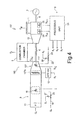
- a plant for the production of electricity comprises a gas turbine assembly 2, an alternator 3, coupled on the same shaft 4, and a device for controlling emissions 5, in particular nitrogen oxides NO x and carbon monoxide CO.
- the gas turbine assembly 2 comprises a compressor 7, which sucks a flowrate of air Q A from outside through an intake duct 8, a combustion chamber 9 and a turbine 10, coupled to the combustion chamber 9 for receiving and expanding a flowrate of exhaust gas Q E .
- An exhaust assembly 11, downstream of the turbine 10, receives and evacuates the flowrate Q E of exhaust gas produced by the gas turbine assembly 2.
- the compressor 7 and the intake duct 8 define a fluidic inlet path to the combustion chamber 9 for the air.
- the compressor 7 is of the multi-stage axial type and is provided with an orientable inlet vane stage or IGV stage (Inlet Guide Vanes) 7a.
- IGV stage Inlet Guide Vanes
- the orienting of the vanes of the IGV stage is determined by way of a IGV actuator 12.
- the flowrate of air Q A sucked by the compressor 7 is conveyed through the intake duct 8, along which is arranged a filter 13 and a conditioning chamber 15, and treated by the compressor 7.
- a residual flowrate Q A ' is fed into the combustion chamber 9.
- a flowrate of fuel Q F is added to the flowrate of air Q A ', in a known way, and the mixture thus obtained is burned.
- the flowrate Q A ' is a fraction of the flowrate Q A and that, by changing the flowrate Q A also the flowrate Q A ' is changed in a substantially proportional way.
- the filter 13 is arranged at the mouth of the intake duct 8 and removes from the sucked air flow solid particles and impurities.
- the conditioning chamber 15 comprises a first heat exchanger 16 and a second heat exchanger 17.
- the first heat exchanger 16 receives a flowrate Q H of a heating fluid through a supply line 19, along which is placed a first control valve 20.
- the second heat exchanger 17 receives a flowrate Q C of a cooling fluid through a supply line 21, along which is placed a second control valve 22.
- the device for controlling emissions 5 comprises a processing unit 23, a first detection cell 25 and a second detection cell 26, both placed in the exhaust assembly 11 of the turbine 10, so as to be invested by the exhaust gas flow.
- the processing unit 23 is a PLC (Programmable Logic Controller) and is coupled to the first detection cell 25 and the second detection cell 26 for receiving measurement signals as described below.
- the processing unit 23 is built into a controller of the plant 1, not shown here in its entirety for simplicity.
- the first detection cell 25 can be an infrared optical cell for the detection of the concentration of carbon monoxide CO, while the second detection cell 26 may be a chemiluminescence type cell for the detection of the concentration of nitrogen oxides NO X .
- the first detection cell 25 and the second detection cell 26 provide to the processing unit 23 respectively a first concentration signal S CO , indicative of the concentration of carbon monoxide CO in the exhaust gas of the turbine 10, and a second concentration signal S NOX , indicative of the concentration of nitrogen oxides NO x in the exhaust gas of the turbine 10.
- the processing unit 23 is configured to determine a first control signal S 1 , a second control signal S 2 and a third control signal S 3 according to the first concentration signal S CO and the second concentration signal S NOX .
- the structure and the operation of the processing unit 23 will be described in more detail below, with reference to Figure 2 .
- the first control signal S 1 is supplied to an actuator 27 of the first control valve 20 and allows regulation of the flowrate of the heating fluid Q H supplied to the first heat exchanger 16 of the conditioning chamber 15.
- the second control signal S 2 is supplied to an actuator 28 of the second control valve 22 and allows regulation of the flowrate of the cooling fluid Q C supplied to the second heat exchanger 17 of the conditioning chamber 15.
- the first control signal S 1 and the signal S 2 represent requests of change of the opening degree respectively of the first control valve 20 and of the second control valve 22 (rather than absolute values of opening). For example, a positive value indicates to the corresponding actuator a request to increase the opening degree of the respective valve, while a negative value indicates a request to reduce the opening degree. For null values, the opening degree of the valves is not changed.
- the third control signal S 3 is supplied to the actuator 12 of the IGV stage 7a and allows to modify the orientation of the vanes of the IGV stage 7a.
- the action of the first heat exchanger 16 and the second heat exchanger 17 allows the regulation of the temperature of the inlet air to the compressor 7, while the orientation of the vanes of the IGV stage 7a determines the flowrate Q A of air sucked by the compressor 7 and fed into the combustion chamber 9.
- FIG. 2 shows the structure of the processing unit 23 according to an embodiment of the invention.
- the processing unit 23 comprises a first subtractor node 30, a second subtractor node 31, a first saturation module 33, a second saturation module 34, a first controller 36, a second controller 37, a third controller 38 and a conflict management module 40.
- the first subtractor node 30 receives the first concentration signal S CO from the first detection cell 25 (not shown here) and a first reference signal S REF1 and calculates a first error signal E CO on the basis of the difference between the first concentration signal S CO , and the first reference signal S REF1 .
- the second subtractor node 31 receives the second concentration signal S NOX from the second detecting cell 26 (not shown here) and a second reference signal S REF2 and calculates a second error signal E NOX on the basis of the difference between the second concentration signal S NOX and the second reference signal S REF2 .
- the reference signal S REF1 and the second reference signal S REF2 are indicative of the respective maximum allowable concentrations and are respectively provided by a first reference generator module 41 and a second reference generator module 42, that can be for example programmable memory elements.
- the first saturation module 33 and the second saturation module 34 receive respectively the first error signal E CO and the second error signal E NOX and provide respectively a first saturated error signal E CO ' and a second error signal E NOX '.
- the first saturated error signal E CO ' and the second saturated error signal E NOX ' respectively coincide with the first error signal E CO and the second error signal E NOX , between a negative saturation value and a positive saturation value; are equal to the negative saturation value, respectively, when the first error signal E CO and the second error signal E NOX are lesser than the negative saturation signal; and are equal to the positive saturation value, respectively, when the first error signal E CO and the second error signal E NOX are greater than the positive saturation value.
- the first controller 36 and the second controller 37 which in the described embodiment are of proportional-integral type, respectively receive the first saturated error signal E CO ' and the second saturated error signal E NOX ' and use them to determine a first nominal control signal S 1 ' and a second nominal control signal S 2 ', which are supplied to the conflict management module 40.
- the conflict management module 40 determines the first control signal S 1 and the second control signal S 2 on the basis of the first nominal control signal S 1 ', the second nominal control signal S 2 ', the first error signal E CO and the second error signal E NOX , in order to avoid the competition of opposing control actions through the first heat exchanger 16 and the second heat exchanger 17, which respectively tend to heat and cool the flowrate Q A of air fed into the combustion chamber 9. More specifically, the conflict management module 40 prioritizes, in case of conflict, the reduction of the concentration of carbon monoxide CO, which is the most appropriate action to stabilize the combustion and therefore minimize polluting emissions. Under stable combustion conditions, the control on the concentration of nitrogen oxides NO x by way of the second heat exchanger 17 can be temporarily excluded.
- the conflict management module 40 calculates the first control signal S 1 and the second control signal S 2 so as to increase the temperature inside the combustion chamber 9, while the action of decreasing the temperature is inhibited.
- the third controller 38 which is also of a proportional-integral type in the described embodiment, receives the second error signal E NOX from the second summing node 31 and uses it to determine the third control signal S 3 , which is fed to the actuator 12 of the IGV stage 7a by the compressor 7 to regulate the flowrate Q A of air.
- the third control signal S 3 tends to increase the flowrate Q A of air and, conversely, when the second error signal E NOX is negative (concentration of nitrogen oxides NO x lower than the allowed limits), the third control signal S 3 tends to reduce the flowrate Q A of air.
- the concentration of nitrogen oxides NO x is kept slightly below the allowable limit, as by doing so the emissions of carbon monoxide CO improve, which are a direct indicator of stable and regular combustion improved in terms of energy efficiency of the heat engine and polluting emissions.
- the emission control device 5 intervenes in the presence of an excess of carbon monoxide CO or nitrogen oxides NO x emissions, by changing the conditions within the combustion chamber 9. More precisely, the emission control device 5 modifies the flowrate Q A of air and its temperature, thus modifying the temperature in the combustion chamber 9, so as to reduce the excessive concentrations of carbon monoxide CO or of nitrogen oxides NO x . If both types of substances are present in excess concentrations, the conflict management module 40 prioritizes the action of reducing emissions of carbon monoxide CO. In doing so, the temperature in the combustion chamber is increased to values which ensure, in accordance with the general conditions of the plant 1, the optimal balance between polluting emissions.
- the solution described has the advantage of directly using the concentrations of pollutants as controlled variables.
- the emission control device 5 intervenes, in fact, on the temperature in the combustion chamber, without however the need to have a measure or an estimate of that temperature.
- the combustion conditions are automatically modified to counteract the excesses with respect to the reference values.
- the control acts directly on the chemical and physical causes of the generation of pollutants and ensures that in the combustion chamber 9 a minimum value of energy is reached for the complete oxidation of carbon, without exceeding the energy value beyond which the production of nitrogen oxides exceeds the permitted limits.
- the solution also pilots the plant towards optimum combustion conditions, regardless of general conditions (specific parameters of the plant, status of aging), for the reason that the emission control device 5 operates directly on the concentrations of pollutants. It is therefore unnecessary a preliminary study of the operating conditions of each machine and optimal combustion conditions, which ensure the best balance between the emissions of carbon monoxide and of nitrogen oxides, are maintained over time even if the overall efficiency of the system tends to degrade.
- the described solution is particularly effective in reducing emissions in the minimum technical environmental conditions.
- the value of the minimum technical environmental power can be reduced.
- Figure 3 shows a possible operating mode of the conflict management module 40.
- the emissions of carbon monoxide CO and nitrogen oxides NO x are maintained within the limits and interventions of the emission control device 5 are not required.
- the first concentration error E CO and the second concentration error E NOX are negative, so the first saturated concentration error E CO ' and the second saturated concentration error E NOX ' are negative or zero, as well as the first nominal control signal S 1 ' and the second nominal control signal S 2 '.
- the conflict management module 40 assigns a null value to the first control signal S 1 and to the second control signal S 2 ( Figure 3 , block 50) and the degree of opening of the first control valve 20 and of the second control valve 22 is not modified.
- the conflict management module 40 then verifies that at least one of either the first error signal E CO or the second error signal E NOX remains respectively below a first activation threshold TH A1 and a second activation threshold TH A2 ( Figure 3 , block 55).
- condition is verified (block 55, output YES), to the first control signal S 1 and to the second control signal S 2 are respectively assigned values of the first nominal control signal S 1 ' and the second nominal control signal S 2 ' (block 60). Therefore, the test of block 55 is repeated. Essentially, the condition is verified if the emissions are below the respective reference values, or in the presence of an imbalance of the emissions for which is requested the intervention of only one of either the first heat exchanger 16 or the second heat exchanger 17. In this case, there are no conflicts or antagonistic actions.
- the first error signal E CO and the second error signal E NOX are both above their respective thresholds (block 55, output NO).
- the conflict management module 40 prioritizes the control action that favours the containment of the concentration of carbon monoxide CO and inhibits the cooling of the flowrate Q A of air.
- the first control signal S 1 is assigned the current value of the first nominal control signal S 1 ' and the second nominal control signal S 2 ' is set to a deactivation value S 20FF , causing the closure of the second control valve 22. Therefore, the second heat exchanger 17 is temporarily excluded and does not participate in the control.
- valve 22 in the presence of the deactivation value S 20FF of the second nominal control signal S 2 ' the valve 22 is placed in a state of minimum opening which, although energetically unfavorable, allows the second heat exchanger 17 to intervene more quickly to the unmet conditions for its inhibition.
- the conflict management module 40 compares the first error signal E CO with a release threshold TH R , lesser than the first activation threshold TH A1 (block 70). Until the first nominal control signal S 1 ' is greater than the release threshold TH R (block 70, output NO), the second heat exchanger 17 remains excluded (block 65). When the first nominal control signal S 1 ' falls below the release threshold TH R (block 70, output YES), the constraint on the control of the concentration of nitrogen oxides NO x by way of the second heat exchanger 17 is released and to the second control signal S 2 is assigned the current value of the second nominal control signal S 2 ' (block 60).
- a plant for the production of electric power 100 comprises a gas turbine assembly 102 in which a compressor 107, equipped with a IGV stage 107a, allows the heat exchange between the elaborated fluid and the outside.
- the first heat exchanger 16 is arranged along the intake duct 8, as previously described, while a second heat exchanger 117 is coupled to the compressor 107.
- the cooling of the flowrate Q A of air for the control of emissions of nitrogen oxides NO x can be accomplished more efficiently after a partial compression.
- Figure 5 shows an embodiment according to which the invention is applied to a combined cycle plant 200.
- the plant 200 comprises the gas turbine assembly 2, the alternator 3, the emission control device 5 and the intake duct 8, along which are placed the first heat exchanger 16 and the second heat exchanger 17.
- the first control valve 20 and the second control valve 22 are driven through the respective actuators 27, 28, by the emission control device 5 so as to control the concentrations of carbon monoxide CO and nitrogen oxides NO X in exhaust gas as described above.
- the system 200 also comprises a steam turbine 202, an alternator 203 coupled upon a same shaft 204 of the steam turbine 202, a heat recovery boiler 205, a capacitor 206 and a degassing element 207.
- the steam turbine 202 comprises a high pressure stage 202a and a medium-low pressure stage 202b.
- the flowrate Q E of exhaust gas provided by the gas turbine assembly 2 is conveyed by way of the heat recovery boiler 205 where there is a circuit 210 for generating steam.
- the circuit 210 comprises a plurality of elements, among which the figure 5 shows:
- a flowrate of steam is drawn off that is used to form the flowrate Q H of heating fluid for the first heat exchanger 16.
- An output flow rate Q H ' from the first heat exchanger 16 is mixed with a flowrate Q W of water withdrawn from the condenser 206 by way of the condensate extraction pump 211. The mixture thus obtained is supplied to the low pressure economizer LTE and then to the degassing element 207.
- the invention can be used for any type of heat engine, such as internal combustion engines (such as Otto cycle or Diesel cycle engines), allowing the same advantages of the application here described for gas turbines.
- internal combustion engines such as Otto cycle or Diesel cycle engines
- conflict management module could be configured to operate according to different modes from that described with reference to Figure 3 .
- the cooling action of the flowrate of air entering the combustion chamber may be favoured, compared to that of heating.
- the action of the first heat exchanger dedicated to heating the flowrate of intake air can be prevented, so as to favour the nullifying of the concentration of nitrogen oxides.
Landscapes
- Engineering & Computer Science (AREA)
- Chemical & Material Sciences (AREA)
- Combustion & Propulsion (AREA)
- Mechanical Engineering (AREA)
- General Engineering & Computer Science (AREA)
- Physics & Mathematics (AREA)
- Fluid Mechanics (AREA)
- Engine Equipment That Uses Special Cycles (AREA)
- Exhaust Gas After Treatment (AREA)
Priority Applications (1)
| Application Number | Priority Date | Filing Date | Title |
|---|---|---|---|
| PL11170073T PL2397670T3 (pl) | 2010-06-15 | 2011-06-15 | Sposób kontrolowania emisji w silniku cieplnym, w szczególności w turbinie gazowej i silnik cieplny |
Applications Claiming Priority (1)
| Application Number | Priority Date | Filing Date | Title |
|---|---|---|---|
| IT001075A ITMI20101075A1 (it) | 2010-06-15 | 2010-06-15 | Metodo per il controllo delle emissioni in una macchina termica, in particolare una turbina a gas, e macchina termica |
Publications (2)
| Publication Number | Publication Date |
|---|---|
| EP2397670A1 EP2397670A1 (en) | 2011-12-21 |
| EP2397670B1 true EP2397670B1 (en) | 2015-03-18 |
Family
ID=43530445
Family Applications (1)
| Application Number | Title | Priority Date | Filing Date |
|---|---|---|---|
| EP11170073.8A Active EP2397670B1 (en) | 2010-06-15 | 2011-06-15 | Method for controlling emissions in a heat engine, in particular a gas turbine, and a heat engine |
Country Status (3)
| Country | Link |
|---|---|
| EP (1) | EP2397670B1 (pl) |
| IT (1) | ITMI20101075A1 (pl) |
| PL (1) | PL2397670T3 (pl) |
Families Citing this family (6)
| Publication number | Priority date | Publication date | Assignee | Title |
|---|---|---|---|---|
| DE102013202982A1 (de) | 2013-02-22 | 2014-08-28 | Siemens Aktiengesellschaft | Verfahren zum Betreiben einer Gasturbine unterhalb ihrer Nennleistung |
| DE102013202984A1 (de) * | 2013-02-22 | 2014-08-28 | Siemens Aktiengesellschaft | Verfahren zum Betreiben einer Gasturbine unterhalb ihrer Nennleistung |
| EP2789829A1 (de) * | 2013-04-12 | 2014-10-15 | Siemens Aktiengesellschaft | Verfahren zur Reduzierung der CO-Emissionen einer Gasturbine sowie Gasturbine |
| EP2824285B1 (en) * | 2013-07-11 | 2016-03-16 | Alstom Technology Ltd | Gas turbine engine comprising an inlet flow control arrangement |
| EP3505741A1 (en) * | 2017-12-29 | 2019-07-03 | Siemens Aktiengesellschaft | Method for operating a gas turbine |
| CN109782584B (zh) * | 2019-01-21 | 2022-05-17 | 杭州澎康自动化科技有限公司 | 一种抽背型汽轮机自整定控制方法 |
Family Cites Families (9)
| Publication number | Priority date | Publication date | Assignee | Title |
|---|---|---|---|---|
| US3975900A (en) * | 1972-02-18 | 1976-08-24 | Engelhard Minerals & Chemicals Corporation | Method and apparatus for turbine system combustor temperature |
| US4951460A (en) * | 1989-01-11 | 1990-08-28 | Stewart & Stevenson Services, Inc. | Apparatus and method for optimizing the air inlet temperature of gas turbines |
| US5697207A (en) * | 1996-08-02 | 1997-12-16 | General Electric Co. | Combined gas turbine inlet chiller, nox control device and power augmentation system and methods of operation |
| SG104914A1 (en) * | 1997-06-30 | 2004-07-30 | Hitachi Ltd | Gas turbine |
| US6513318B1 (en) * | 2000-11-29 | 2003-02-04 | Hybrid Power Generation Systems Llc | Low emissions gas turbine engine with inlet air heating |
| ITMI20022757A1 (it) * | 2002-12-23 | 2004-06-24 | Nuovo Pignone Spa | Sistema di controllo ed ottimizzazione delle emissioni |
| US7032388B2 (en) * | 2003-11-17 | 2006-04-25 | General Electric Company | Method and system for incorporating an emission sensor into a gas turbine controller |
| US20090053036A1 (en) * | 2007-08-24 | 2009-02-26 | General Electric Company | Systems and Methods for Extending Gas Turbine Emissions Compliance |
| US8474241B2 (en) * | 2007-09-05 | 2013-07-02 | Solar Turbines Inc. | Engine with intake air temperature control system |
-
2010
- 2010-06-15 IT IT001075A patent/ITMI20101075A1/it unknown
-
2011
- 2011-06-15 EP EP11170073.8A patent/EP2397670B1/en active Active
- 2011-06-15 PL PL11170073T patent/PL2397670T3/pl unknown
Also Published As
| Publication number | Publication date |
|---|---|
| PL2397670T3 (pl) | 2015-08-31 |
| EP2397670A1 (en) | 2011-12-21 |
| ITMI20101075A1 (it) | 2011-12-16 |
Similar Documents
| Publication | Publication Date | Title |
|---|---|---|
| EP2397670B1 (en) | Method for controlling emissions in a heat engine, in particular a gas turbine, and a heat engine | |
| RU2665773C2 (ru) | Способ работы газотурбинной установки со ступенчатым и/или последовательным сгоранием | |
| US8561555B2 (en) | Oxyfuel combustion boiler plant and operating method for the same | |
| JP5962534B2 (ja) | インタークーラの温度制御装置 | |
| RU2585891C2 (ru) | Контроль состава газа в газотурбинной электростанции с рециркуляцией отработавших газов | |
| US20150377146A1 (en) | Erosion suppression system and method in an exhaust gas recirculation gas turbine system | |
| JP2009062981A (ja) | ガスタービンの部分負荷運転条件のための方法及びシステム | |
| RU2014151777A (ru) | Система и способы для управления конденсатом в воздушном тракте двигателя | |
| US20110179793A1 (en) | Method for operating an internal combustion engine having a steam power plant | |
| EP2584166A1 (en) | Power plant and method for retrofit | |
| EP3240947A1 (en) | Systems and methods of estimating a combustion equivalence ratio in a gas turbine with exhaust gas recirculation | |
| CA2997124A1 (en) | Method and apparatus for utilization of hot water plant waste heat recovery by incorporated high temperature water source heat pump | |
| KR20220138407A (ko) | 복수의 배기 가스 재순환 냉각기의 관리를 위한 시스템 및 방법 | |
| JP6444778B2 (ja) | エンジン、及び当該エンジンを備えた作業車両 | |
| US8844295B2 (en) | Method for meeting a purge flow requirement for a power plant and a power plant having a purge control system | |
| EP2837778A1 (en) | Operation of a gas turbine power plant with carbon dioxide separation | |
| JP4892539B2 (ja) | 複合発電プラント及び排熱回収ボイラ | |
| CN112513442B (zh) | 用于运行具有气态燃料的燃气轮机设施的方法 | |
| EP3047129B1 (en) | Method of controlling emissions of a gas turbine plant and gas turbine plant | |
| US11255218B2 (en) | Method for starting up a gas turbine engine of a combined cycle power plant | |
| KR102338341B1 (ko) | 엔진 시스템 | |
| US12448937B1 (en) | System and method for operating exhaust gas recirculation in gas turbines | |
| JP2007285553A (ja) | 燃焼ボイラの制御方法 | |
| CN219735354U (zh) | 一种燃气锅炉的烟气排放系统 | |
| RU61814U1 (ru) | Газоперекачивающая компрессорная станция магистрального газопровода |
Legal Events
| Date | Code | Title | Description |
|---|---|---|---|
| AK | Designated contracting states |
Kind code of ref document: A1 Designated state(s): AL AT BE BG CH CY CZ DE DK EE ES FI FR GB GR HR HU IE IS IT LI LT LU LV MC MK MT NL NO PL PT RO RS SE SI SK SM TR |
|
| AX | Request for extension of the european patent |
Extension state: BA ME |
|
| PUAI | Public reference made under article 153(3) epc to a published international application that has entered the european phase |
Free format text: ORIGINAL CODE: 0009012 |
|
| 17P | Request for examination filed |
Effective date: 20120621 |
|
| RIC1 | Information provided on ipc code assigned before grant |
Ipc: F02C 7/143 20060101ALI20140730BHEP Ipc: F02C 9/20 20060101ALI20140730BHEP Ipc: F02C 1/04 20060101AFI20140730BHEP |
|
| GRAP | Despatch of communication of intention to grant a patent |
Free format text: ORIGINAL CODE: EPIDOSNIGR1 |
|
| INTG | Intention to grant announced |
Effective date: 20141008 |
|
| GRAS | Grant fee paid |
Free format text: ORIGINAL CODE: EPIDOSNIGR3 |
|
| GRAA | (expected) grant |
Free format text: ORIGINAL CODE: 0009210 |
|
| AK | Designated contracting states |
Kind code of ref document: B1 Designated state(s): AL AT BE BG CH CY CZ DE DK EE ES FI FR GB GR HR HU IE IS IT LI LT LU LV MC MK MT NL NO PL PT RO RS SE SI SK SM TR |
|
| REG | Reference to a national code |
Ref country code: GB Ref legal event code: FG4D |
|
| REG | Reference to a national code |
Ref country code: CH Ref legal event code: EP |
|
| REG | Reference to a national code |
Ref country code: IE Ref legal event code: FG4D |
|
| REG | Reference to a national code |
Ref country code: AT Ref legal event code: REF Ref document number: 716740 Country of ref document: AT Kind code of ref document: T Effective date: 20150415 |
|
| REG | Reference to a national code |
Ref country code: DE Ref legal event code: R096 Ref document number: 602011014725 Country of ref document: DE Effective date: 20150430 |
|
| REG | Reference to a national code |
Ref country code: NL Ref legal event code: VDEP Effective date: 20150318 |
|
| REG | Reference to a national code |
Ref country code: NL Ref legal event code: VDEP Effective date: 20150318 |
|
| PG25 | Lapsed in a contracting state [announced via postgrant information from national office to epo] |
Ref country code: SE Free format text: LAPSE BECAUSE OF FAILURE TO SUBMIT A TRANSLATION OF THE DESCRIPTION OR TO PAY THE FEE WITHIN THE PRESCRIBED TIME-LIMIT Effective date: 20150318 Ref country code: FI Free format text: LAPSE BECAUSE OF FAILURE TO SUBMIT A TRANSLATION OF THE DESCRIPTION OR TO PAY THE FEE WITHIN THE PRESCRIBED TIME-LIMIT Effective date: 20150318 Ref country code: LT Free format text: LAPSE BECAUSE OF FAILURE TO SUBMIT A TRANSLATION OF THE DESCRIPTION OR TO PAY THE FEE WITHIN THE PRESCRIBED TIME-LIMIT Effective date: 20150318 Ref country code: NO Free format text: LAPSE BECAUSE OF FAILURE TO SUBMIT A TRANSLATION OF THE DESCRIPTION OR TO PAY THE FEE WITHIN THE PRESCRIBED TIME-LIMIT Effective date: 20150618 Ref country code: HR Free format text: LAPSE BECAUSE OF FAILURE TO SUBMIT A TRANSLATION OF THE DESCRIPTION OR TO PAY THE FEE WITHIN THE PRESCRIBED TIME-LIMIT Effective date: 20150318 |
|
| REG | Reference to a national code |
Ref country code: AT Ref legal event code: MK05 Ref document number: 716740 Country of ref document: AT Kind code of ref document: T Effective date: 20150318 |
|
| REG | Reference to a national code |
Ref country code: LT Ref legal event code: MG4D |
|
| PG25 | Lapsed in a contracting state [announced via postgrant information from national office to epo] |
Ref country code: RS Free format text: LAPSE BECAUSE OF FAILURE TO SUBMIT A TRANSLATION OF THE DESCRIPTION OR TO PAY THE FEE WITHIN THE PRESCRIBED TIME-LIMIT Effective date: 20150318 Ref country code: GR Free format text: LAPSE BECAUSE OF FAILURE TO SUBMIT A TRANSLATION OF THE DESCRIPTION OR TO PAY THE FEE WITHIN THE PRESCRIBED TIME-LIMIT Effective date: 20150619 Ref country code: LV Free format text: LAPSE BECAUSE OF FAILURE TO SUBMIT A TRANSLATION OF THE DESCRIPTION OR TO PAY THE FEE WITHIN THE PRESCRIBED TIME-LIMIT Effective date: 20150318 |
|
| REG | Reference to a national code |
Ref country code: PL Ref legal event code: T3 |
|
| PG25 | Lapsed in a contracting state [announced via postgrant information from national office to epo] |
Ref country code: NL Free format text: LAPSE BECAUSE OF FAILURE TO SUBMIT A TRANSLATION OF THE DESCRIPTION OR TO PAY THE FEE WITHIN THE PRESCRIBED TIME-LIMIT Effective date: 20150318 |
|
| PG25 | Lapsed in a contracting state [announced via postgrant information from national office to epo] |
Ref country code: PT Free format text: LAPSE BECAUSE OF FAILURE TO SUBMIT A TRANSLATION OF THE DESCRIPTION OR TO PAY THE FEE WITHIN THE PRESCRIBED TIME-LIMIT Effective date: 20150720 Ref country code: EE Free format text: LAPSE BECAUSE OF FAILURE TO SUBMIT A TRANSLATION OF THE DESCRIPTION OR TO PAY THE FEE WITHIN THE PRESCRIBED TIME-LIMIT Effective date: 20150318 Ref country code: ES Free format text: LAPSE BECAUSE OF FAILURE TO SUBMIT A TRANSLATION OF THE DESCRIPTION OR TO PAY THE FEE WITHIN THE PRESCRIBED TIME-LIMIT Effective date: 20150318 Ref country code: SK Free format text: LAPSE BECAUSE OF FAILURE TO SUBMIT A TRANSLATION OF THE DESCRIPTION OR TO PAY THE FEE WITHIN THE PRESCRIBED TIME-LIMIT Effective date: 20150318 Ref country code: CZ Free format text: LAPSE BECAUSE OF FAILURE TO SUBMIT A TRANSLATION OF THE DESCRIPTION OR TO PAY THE FEE WITHIN THE PRESCRIBED TIME-LIMIT Effective date: 20150318 Ref country code: RO Free format text: LAPSE BECAUSE OF FAILURE TO SUBMIT A TRANSLATION OF THE DESCRIPTION OR TO PAY THE FEE WITHIN THE PRESCRIBED TIME-LIMIT Effective date: 20150318 |
|
| PG25 | Lapsed in a contracting state [announced via postgrant information from national office to epo] |
Ref country code: IS Free format text: LAPSE BECAUSE OF FAILURE TO SUBMIT A TRANSLATION OF THE DESCRIPTION OR TO PAY THE FEE WITHIN THE PRESCRIBED TIME-LIMIT Effective date: 20150718 Ref country code: AT Free format text: LAPSE BECAUSE OF FAILURE TO SUBMIT A TRANSLATION OF THE DESCRIPTION OR TO PAY THE FEE WITHIN THE PRESCRIBED TIME-LIMIT Effective date: 20150318 |
|
| REG | Reference to a national code |
Ref country code: DE Ref legal event code: R097 Ref document number: 602011014725 Country of ref document: DE |
|
| PLBE | No opposition filed within time limit |
Free format text: ORIGINAL CODE: 0009261 |
|
| STAA | Information on the status of an ep patent application or granted ep patent |
Free format text: STATUS: NO OPPOSITION FILED WITHIN TIME LIMIT |
|
| PG25 | Lapsed in a contracting state [announced via postgrant information from national office to epo] |
Ref country code: DK Free format text: LAPSE BECAUSE OF FAILURE TO SUBMIT A TRANSLATION OF THE DESCRIPTION OR TO PAY THE FEE WITHIN THE PRESCRIBED TIME-LIMIT Effective date: 20150318 Ref country code: MC Free format text: LAPSE BECAUSE OF FAILURE TO SUBMIT A TRANSLATION OF THE DESCRIPTION OR TO PAY THE FEE WITHIN THE PRESCRIBED TIME-LIMIT Effective date: 20150318 |
|
| REG | Reference to a national code |
Ref country code: CH Ref legal event code: PL |
|
| 26N | No opposition filed |
Effective date: 20151221 |
|
| GBPC | Gb: european patent ceased through non-payment of renewal fee |
Effective date: 20150618 |
|
| PG25 | Lapsed in a contracting state [announced via postgrant information from national office to epo] |
Ref country code: SI Free format text: LAPSE BECAUSE OF FAILURE TO SUBMIT A TRANSLATION OF THE DESCRIPTION OR TO PAY THE FEE WITHIN THE PRESCRIBED TIME-LIMIT Effective date: 20150318 Ref country code: LU Free format text: LAPSE BECAUSE OF FAILURE TO SUBMIT A TRANSLATION OF THE DESCRIPTION OR TO PAY THE FEE WITHIN THE PRESCRIBED TIME-LIMIT Effective date: 20150615 |
|
| REG | Reference to a national code |
Ref country code: IE Ref legal event code: MM4A |
|
| REG | Reference to a national code |
Ref country code: FR Ref legal event code: ST Effective date: 20160229 |
|
| PG25 | Lapsed in a contracting state [announced via postgrant information from national office to epo] |
Ref country code: CH Free format text: LAPSE BECAUSE OF NON-PAYMENT OF DUE FEES Effective date: 20150630 Ref country code: LI Free format text: LAPSE BECAUSE OF NON-PAYMENT OF DUE FEES Effective date: 20150630 Ref country code: IE Free format text: LAPSE BECAUSE OF NON-PAYMENT OF DUE FEES Effective date: 20150615 Ref country code: GB Free format text: LAPSE BECAUSE OF NON-PAYMENT OF DUE FEES Effective date: 20150618 |
|
| PG25 | Lapsed in a contracting state [announced via postgrant information from national office to epo] |
Ref country code: FR Free format text: LAPSE BECAUSE OF NON-PAYMENT OF DUE FEES Effective date: 20150630 |
|
| PG25 | Lapsed in a contracting state [announced via postgrant information from national office to epo] |
Ref country code: BE Free format text: LAPSE BECAUSE OF FAILURE TO SUBMIT A TRANSLATION OF THE DESCRIPTION OR TO PAY THE FEE WITHIN THE PRESCRIBED TIME-LIMIT Effective date: 20150318 |
|
| PG25 | Lapsed in a contracting state [announced via postgrant information from national office to epo] |
Ref country code: MT Free format text: LAPSE BECAUSE OF FAILURE TO SUBMIT A TRANSLATION OF THE DESCRIPTION OR TO PAY THE FEE WITHIN THE PRESCRIBED TIME-LIMIT Effective date: 20150318 |
|
| PG25 | Lapsed in a contracting state [announced via postgrant information from national office to epo] |
Ref country code: HU Free format text: LAPSE BECAUSE OF FAILURE TO SUBMIT A TRANSLATION OF THE DESCRIPTION OR TO PAY THE FEE WITHIN THE PRESCRIBED TIME-LIMIT; INVALID AB INITIO Effective date: 20110615 Ref country code: BG Free format text: LAPSE BECAUSE OF FAILURE TO SUBMIT A TRANSLATION OF THE DESCRIPTION OR TO PAY THE FEE WITHIN THE PRESCRIBED TIME-LIMIT Effective date: 20150318 Ref country code: SM Free format text: LAPSE BECAUSE OF FAILURE TO SUBMIT A TRANSLATION OF THE DESCRIPTION OR TO PAY THE FEE WITHIN THE PRESCRIBED TIME-LIMIT Effective date: 20150318 |
|
| PG25 | Lapsed in a contracting state [announced via postgrant information from national office to epo] |
Ref country code: CY Free format text: LAPSE BECAUSE OF FAILURE TO SUBMIT A TRANSLATION OF THE DESCRIPTION OR TO PAY THE FEE WITHIN THE PRESCRIBED TIME-LIMIT Effective date: 20150318 |
|
| PG25 | Lapsed in a contracting state [announced via postgrant information from national office to epo] |
Ref country code: MK Free format text: LAPSE BECAUSE OF FAILURE TO SUBMIT A TRANSLATION OF THE DESCRIPTION OR TO PAY THE FEE WITHIN THE PRESCRIBED TIME-LIMIT Effective date: 20150318 |
|
| PG25 | Lapsed in a contracting state [announced via postgrant information from national office to epo] |
Ref country code: AL Free format text: LAPSE BECAUSE OF FAILURE TO SUBMIT A TRANSLATION OF THE DESCRIPTION OR TO PAY THE FEE WITHIN THE PRESCRIBED TIME-LIMIT Effective date: 20150318 |
|
| PG25 | Lapsed in a contracting state [announced via postgrant information from national office to epo] |
Ref country code: PL Free format text: LAPSE BECAUSE OF NON-PAYMENT OF DUE FEES Effective date: 20180615 |
|
| P01 | Opt-out of the competence of the unified patent court (upc) registered |
Effective date: 20240430 |
|
| PGFP | Annual fee paid to national office [announced via postgrant information from national office to epo] |
Ref country code: DE Payment date: 20250618 Year of fee payment: 15 |
|
| PGFP | Annual fee paid to national office [announced via postgrant information from national office to epo] |
Ref country code: TR Payment date: 20250612 Year of fee payment: 15 |
|
| PGFP | Annual fee paid to national office [announced via postgrant information from national office to epo] |
Ref country code: IT Payment date: 20250630 Year of fee payment: 15 |