EP2397645B1 - Mono-gesteuerte motorisch angetriebene Jalousie - Google Patents
Mono-gesteuerte motorisch angetriebene Jalousie Download PDFInfo
- Publication number
- EP2397645B1 EP2397645B1 EP11169936.9A EP11169936A EP2397645B1 EP 2397645 B1 EP2397645 B1 EP 2397645B1 EP 11169936 A EP11169936 A EP 11169936A EP 2397645 B1 EP2397645 B1 EP 2397645B1
- Authority
- EP
- European Patent Office
- Prior art keywords
- winding
- shaft
- intended
- blades
- motorized blind
- Prior art date
- Legal status (The legal status is an assumption and is not a legal conclusion. Google has not performed a legal analysis and makes no representation as to the accuracy of the status listed.)
- Active
Links
Images

Classifications
-
- E—FIXED CONSTRUCTIONS
- E06—DOORS, WINDOWS, SHUTTERS, OR ROLLER BLINDS IN GENERAL; LADDERS
- E06B—FIXED OR MOVABLE CLOSURES FOR OPENINGS IN BUILDINGS, VEHICLES, FENCES OR LIKE ENCLOSURES IN GENERAL, e.g. DOORS, WINDOWS, BLINDS, GATES
- E06B9/00—Screening or protective devices for wall or similar openings, with or without operating or securing mechanisms; Closures of similar construction
- E06B9/24—Screens or other constructions affording protection against light, especially against sunshine; Similar screens for privacy or appearance; Slat blinds
- E06B9/26—Lamellar or like blinds, e.g. venetian blinds
- E06B9/28—Lamellar or like blinds, e.g. venetian blinds with horizontal lamellae, e.g. non-liftable
- E06B9/30—Lamellar or like blinds, e.g. venetian blinds with horizontal lamellae, e.g. non-liftable liftable
- E06B9/32—Operating, guiding, or securing devices therefor
- E06B9/322—Details of operating devices, e.g. pulleys, brakes, spring drums, drives
-
- E—FIXED CONSTRUCTIONS
- E06—DOORS, WINDOWS, SHUTTERS, OR ROLLER BLINDS IN GENERAL; LADDERS
- E06B—FIXED OR MOVABLE CLOSURES FOR OPENINGS IN BUILDINGS, VEHICLES, FENCES OR LIKE ENCLOSURES IN GENERAL, e.g. DOORS, WINDOWS, BLINDS, GATES
- E06B9/00—Screening or protective devices for wall or similar openings, with or without operating or securing mechanisms; Closures of similar construction
- E06B9/56—Operating, guiding or securing devices or arrangements for roll-type closures; Spring drums; Tape drums; Counterweighting arrangements therefor
- E06B9/68—Operating devices or mechanisms, e.g. with electric drive
-
- E—FIXED CONSTRUCTIONS
- E06—DOORS, WINDOWS, SHUTTERS, OR ROLLER BLINDS IN GENERAL; LADDERS
- E06B—FIXED OR MOVABLE CLOSURES FOR OPENINGS IN BUILDINGS, VEHICLES, FENCES OR LIKE ENCLOSURES IN GENERAL, e.g. DOORS, WINDOWS, BLINDS, GATES
- E06B9/00—Screening or protective devices for wall or similar openings, with or without operating or securing mechanisms; Closures of similar construction
- E06B9/56—Operating, guiding or securing devices or arrangements for roll-type closures; Spring drums; Tape drums; Counterweighting arrangements therefor
- E06B9/80—Safety measures against dropping or unauthorised opening; Braking or immobilising devices; Devices for limiting unrolling
- E06B9/82—Safety measures against dropping or unauthorised opening; Braking or immobilising devices; Devices for limiting unrolling automatic
- E06B9/88—Safety measures against dropping or unauthorised opening; Braking or immobilising devices; Devices for limiting unrolling automatic for limiting unrolling
-
- E—FIXED CONSTRUCTIONS
- E06—DOORS, WINDOWS, SHUTTERS, OR ROLLER BLINDS IN GENERAL; LADDERS
- E06B—FIXED OR MOVABLE CLOSURES FOR OPENINGS IN BUILDINGS, VEHICLES, FENCES OR LIKE ENCLOSURES IN GENERAL, e.g. DOORS, WINDOWS, BLINDS, GATES
- E06B9/00—Screening or protective devices for wall or similar openings, with or without operating or securing mechanisms; Closures of similar construction
- E06B9/56—Operating, guiding or securing devices or arrangements for roll-type closures; Spring drums; Tape drums; Counterweighting arrangements therefor
- E06B9/80—Safety measures against dropping or unauthorised opening; Braking or immobilising devices; Devices for limiting unrolling
- E06B9/82—Safety measures against dropping or unauthorised opening; Braking or immobilising devices; Devices for limiting unrolling automatic
- E06B9/90—Safety measures against dropping or unauthorised opening; Braking or immobilising devices; Devices for limiting unrolling automatic for immobilising the closure member in various chosen positions
-
- E—FIXED CONSTRUCTIONS
- E06—DOORS, WINDOWS, SHUTTERS, OR ROLLER BLINDS IN GENERAL; LADDERS
- E06B—FIXED OR MOVABLE CLOSURES FOR OPENINGS IN BUILDINGS, VEHICLES, FENCES OR LIKE ENCLOSURES IN GENERAL, e.g. DOORS, WINDOWS, BLINDS, GATES
- E06B9/00—Screening or protective devices for wall or similar openings, with or without operating or securing mechanisms; Closures of similar construction
- E06B9/56—Operating, guiding or securing devices or arrangements for roll-type closures; Spring drums; Tape drums; Counterweighting arrangements therefor
- E06B9/68—Operating devices or mechanisms, e.g. with electric drive
- E06B2009/6809—Control
- E06B2009/6872—Control using counters to determine shutter position
- E06B2009/6881—Mechanical counters
-
- E—FIXED CONSTRUCTIONS
- E06—DOORS, WINDOWS, SHUTTERS, OR ROLLER BLINDS IN GENERAL; LADDERS
- E06B—FIXED OR MOVABLE CLOSURES FOR OPENINGS IN BUILDINGS, VEHICLES, FENCES OR LIKE ENCLOSURES IN GENERAL, e.g. DOORS, WINDOWS, BLINDS, GATES
- E06B9/00—Screening or protective devices for wall or similar openings, with or without operating or securing mechanisms; Closures of similar construction
- E06B9/56—Operating, guiding or securing devices or arrangements for roll-type closures; Spring drums; Tape drums; Counterweighting arrangements therefor
- E06B9/68—Operating devices or mechanisms, e.g. with electric drive
- E06B9/72—Operating devices or mechanisms, e.g. with electric drive comprising an electric motor positioned inside the roller
Definitions
- the present invention relates to a motorized blind comprising a winding shaft and an apron integral with the winding shaft and whose deployment of the deck is able to be interrupted when it encounters an obstacle.
- Known motorized blinds with adjustable blades are installed along the bay windows. They comprise on the one hand a winding shaft mounted in an upper part of the bay and a set of stackable blades having a terminal support blade capable of stackably receiving the other blades of said set of blades.
- the winding shaft is controllable in rotation by means of an electric motor.
- the blinds comprise retaining means for retaining each of said blades and drive ribbons, usually called lacettes, and connecting said terminal support blade and the winding shaft freely passing through the other blades.
- the ribbons are able to be wrapped around the winding shaft, while the free support blade exerts on them a tension under the effect of gravity.
- the winding shaft is intended to be rotated to unwind the ribbons and cause the vertical drive of the terminal support blade in translation between a close position and a position remote from said shaft in which said retaining means retain from close to near said other blades facing said bay, while said final blade is suspended from the ribbons.
- the motorized blind further comprises a stop mechanism comprising a control rod pivotally mounted in a direction substantially parallel to the winding shaft and adapted to come into contact with at least one of the ribbons.
- a stop mechanism comprising a control rod pivotally mounted in a direction substantially parallel to the winding shaft and adapted to come into contact with at least one of the ribbons.
- the disadvantage of this device lies in the reliability of the stop mechanism and the rotation stop control of the winding shaft.
- the control rod has a certain flexibility which requires a complete release of the ribbon for the switch is actuated, and efforts to exert on it to control the stopping of the electric motor are relatively important.
- the motorized blind has only one stop mechanism for a single ribbon winding, and the final blade encounters an obstacle next to another ribbon winding, not equipped, it will take several seconds before that said other ribbon winding finally feels the voltage anomaly; the final blade then being stopped while it has a very pronounced slope, which is both unsightly and risky.
- We can of course overcome this disadvantage by equipping each of the ribbon windings around the winding shaft of a stop mechanism, but we find us quickly having to manage many electrical conductors, including microswitches and a box electric. This significantly increases the price of the product.
- a problem that arises and that aims to solve the present invention is to provide a motorized blind including a stop mechanism more reliable and more economical, capable of interrupting the movement of the final blade, regardless of the location where is the obstacle.
- the present invention provides a motorized blind according to claim 1.
- a feature of the invention lies in the implementation of a stop mechanism, maintained in a fixed position along the winding shaft, which does not act on a switch to cut off the power supply.
- the drive motor of the shaft but which comes directly into engagement with the shaft to lock it mechanically and thus interrupt the electric motor.
- the latter is equipped, for example, with a device for measuring the rotational speed of its rotor, and when this speed undergoes a sudden change, in this case a deceleration, the power supply is then cut off instantly and the engine stopped.
- the winding shaft is instantly mechanically locked in rotation and it is this blockage which causes the stop of the electric motor which drives it. Therefore, the reliability of the stop mechanism, and hence the efficiency of the rotational stop of the winding shaft is large. Also, as soon as the lower ballast meets an obstacle, and the windable portion relaxes, the winding shaft whose rotation allows the deployment of the deck, is instantly immobilized.
- the rollable portion relaxes, not only at the end of the race of the lower ballast border, but when the lower ballast border meets an obstacle, in any of the positions between a close position of the shaft winding and a position away from the winding shaft.
- Said stop mechanism is located outside said winding shaft, while said at least one windable portion extends between said stop mechanism and said winding shaft. In this way, it is easier to detect the loosening of the roll-up part when it occurs, whatever the position of the lower ballast border.
- said winding shaft comprises a tubular member adapted to receive a tubular motor inside said tubular member for driving said tubular member in rotation.
- the motorized blind can not only be produced at an advantageous cost, because these tubular motors associated with a tubular member are produced in large series for many other applications and therefore at an advantageous cost. They are used in particular for shutter type applications. They are also more compact.
- motorized blinds according to the prior art, are usually equipped with a central motor dual output and therefore double reducer, which makes them on the one hand more complex, and on the other hand more expensive. In addition they are larger, and therefore the housing that hosts such a type of engine must also be of a larger volume.
- the winding shaft advantageously has a catching tooth intended to cooperate with said stop mechanism to mechanically lock said winding shaft in rotation.
- the stop mechanism advantageously comprises a movable feeler member having a first fixing end and a first contact end opposite said first fixing end and able to come into contact with said at least one rollable part.
- the first fixing end is preferably pivotally mounted along an axis substantially parallel to said winding shaft.
- the feeler member pivots, for example in a cradle traversed by the winding shaft, which cradle is mounted in a fixed position in the aforementioned casing.
- the contact end of the feeler member, against which the rollable portion is frictionally driven, extends substantially perpendicular to the center of the winding shaft, while the fastening end extends in a position offset laterally from the center of the shaft.
- the probe member thus extends in arc opposite the winding shaft.
- said stop mechanism comprises a return spring of said feeler member for driving said feeler member in motion when said at least one rollable portion relaxes.
- said feeler member is pivotally driven when said at least one rollable portion expands.
- the rollable portion when it is under tension under the weight of the lower ballast edge, it then exerts a force on the contact end of the feeler member which is then held in a pivoted position where its contact end is removed of the winding shaft and in which the return spring is compressed.
- the rollable portion relaxes and the return spring causes the pivoting of the feeler member and bringing the contact end of the winding shaft. It is this pivoting of the feeler member that allows the stop mechanism to engage the winding shaft to mechanically lock it.
- said stop mechanism comprises a movable locking member having a second fixing end and a second end of contact opposite to said second fixing end adapted to engage said winding shaft.
- the second fixing end of the locking member is pivotally mounted along an axis substantially parallel to said winding shaft.
- the feeler member and the locking member form two distinct pieces, and said feeler member is intended to be driven in motion to come into contact with said locking member. in order to drive said locking member in motion.
- said feeler member pivots to come into contact with said locking member so as to cause said locking member which pivots in turn.
- feeler member and the locking member may also, according to yet another embodiment, be movably mounted in translation to perform functions identical to the stop mechanisms. It is also envisaged that one is mobile in translation while the other is pivotal.
- said apron comprises, on the one hand, a set of blades having a terminal support blade forming said lower ballast border, and on the other hand at least one drive ribbon passing through said other blades and forming said at least one rollable portion.
- said shaft has a circular track for receiving said at least one coiled drive tape.
- the circular track is formed in the bottom of a grooved pulley, so as to guide perfectly the winding of the tape on itself.
- the apron may also consist of a fabric adapted to be wound around the winding shaft, and the rollable part adapted to cooperate with the stop mechanism is formed by one of the side edges. of said canvas.
- the motorized blind further comprises: adjustable retaining means comprising a cord and an angular segment integral with said cord, together forming a loop around said winding shaft, said angular segment being able to be angularly driven by friction by said shaft to adjust the orientation of said blades; and also a mobile locking cap for blocking said angular segment with respect to said winding shaft in an intermediate angular position corresponding to a determined orientation of said blades; and finally, an unlocking element for driving said movable locking cap and for causing the release of said angular segment when said at least one driving tape is unwound.
- adjustable retaining means comprising a cord and an angular segment integral with said cord, together forming a loop around said winding shaft, said angular segment being able to be angularly driven by friction by said shaft to adjust the orientation of said blades
- a mobile locking cap for blocking said angular segment with respect to said winding shaft in an intermediate angular position corresponding to a determined orientation of said blades
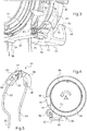
- the Figure 1 partially illustrates a winding shaft comprising a tubular member 10 adapted to receive inside a tubular motor not shown.
- the tubular member 10 extends longitudinally along an axis of symmetry A and here passes through a return assembly 14, which comprises a cradle 16 intended to be held in a fixed position inside a longitudinal casing not shown and including the tubular member 10.
- the cradle 16 accommodates inside a functional sleeve 18 in which is fitted the tubular member 10 and to which it is connected in rotation through a longitudinal groove 20 of the tubular member 10.
- the cradle 16 has an upper window 17 and it comprises a movable cover 22 installed through the upper window 17 and which is adapted to cooperate with the functional sleeve 18 as will be explained hereinafter.
- the movable hood 22 has in each of its corners, a fastening pin 19 and the fixing studs 19 of the movable cowl 22 are respectively engaged in an oblong orifice 23. Thanks to the oblong holes which extend in the lateral edges of the upper window 17, in directions which cut the tubular member 10, the cover 22 is movable in translation between a close position and a position away from the functional sleeve 18, while remaining prisoner of the cradle 16.
- Such a blind comprises a winding shaft formed of the tubular member 10 and a set of blades having a terminal support blade, or final blade, adapted to receive in stack the other blades of said set of blades.
- a blind further comprises at least one other lift assembly 14 identical and spaced from the first.
- the tubular member 10 is equipped with at least one lift assembly at each of its ends.
- the motorized blind comprises, for each of the lift assemblies 14, a drive tape 24 forming the roll-up part and intended to connect the not shown support blade and the winding shaft formed of the tubular member 10.
- the drive ribbon 24 is able to pass through the other blades of the blade set not shown here.
- the drive tape 24 is thus wound on itself around a circular track formed around the functional sleeve 18 and hidden, on the Figure 2 by the coaxial ribs 26, 28.
- the not shown support blade exerts a tension T on the ribbon in a direction opposite to the functional sleeve 18.
- the latter has an axial inner rib 30 intended to engage inside the longitudinal groove 20 of the tubular member 10 illustrated in FIG. Figure 1 , so that the rotational movement of the tubular member 10 induces the rotation of the functional sleeve 18 and causes the unwinding of the tape and thus the drive of the terminal support blade in translation opposite the tubular member 10.
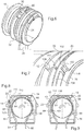
- the functional sleeve 18 has, on the one hand, a groove 32 of trapezoidal axial section, adjacent to the pulley formed by the two coaxial ribs 26, 28, and which will be described below in more detail on the Figure 6 and on the other hand a truncated rib 34 circular.
- This truncated rib 34 constitutes a rock wheel and it extends in a plane substantially perpendicular to the axis of the functional sleeve 18 and the tubular member 10, opposite the pulley formed by the two coaxial ribs 26, 28 with respect to the trapezoidal groove 32. It defines a first free end 36 forming a hooking tooth projecting from the functional sleeve 18 with two opposite reinforcing cheeks 38, 40, on each side and joined by a bridge 42 which extends in an axial direction. Opposite the first free end 36 forming a hooking tooth, the truncated rib 34 has a second free end 44 chamfered and able to form ramp. Also, the truncated rib 34 has a notch 45 between its two opposite free ends 36, 44.
- the motorized blind comprises a stop mechanism 46 installed along the functional sleeve 18, and integral with the cradle 16 not shown in this Figure 2 .
- This stop mechanism 46 first comprises a feeler member 48 installed facing the pulley formed by the two adjacent coaxial ribs 26, 28 to cooperate with the ribbon 24 and a locking member 50 installed opposite the truncated rib. 34 to cooperate with the hooking tooth 36.
- the blocking member 50 and the feeler member 48 are thus mounted at a distance from one another along the functional sleeve 18.
- the locking member 50 has a general prismatic shape, the advantages of which will be explained below, whereas the feeler member 48 extends in an arc.
- the latter has a first fixing end 52 on the inside of the cradle 16 and a first opposite contact end 54 against which the ribbon 24 comes to bear substantially perpendicular to the axis M of the functional sleeve 18.
- the first contact end 54 and the first attachment end 52 are radially spaced from the tubular sleeve 18 substantially the same distance and angularly offset relative to each other vis-a-vis the functional sleeve 18.
- the stop mechanism 46 is located outside the functional sleeve 18 so as to be actuable while the drive tape 24 is still wound around the functional sleeve 18.
- the feeler member 48 is presented in a vacuum on the Figure 2 for explanation purposes.
- its attachment end 52 is pivotally mounted on the inside of the cradle 16 about a feeler member axis 56 substantially parallel to the axis M of the functional sleeve 18.
- the feeler member 48 has a heel 58 in which is housed a return spring 60 adapted to extend behind the feeler member 48 to abut against the inside of the cradle 16. Therefore, the feeler member 48 is rotated by the return spring 60 for driving the first contact end 54 towards the functional sleeve 18.
- the locking member 50 has a second fastening end 62 pivotally mounted on the inside of the cradle 16 around a locking member axis 64 substantially parallel to the feeler member axis 56. In contrast to the second fixing end 62, the locking member 50 has a second contact end 66 having a return 68 forming a hook oriented towards the axis M of the functional sleeve 18.
- the feeler member 48 has between these two opposite ends 54, 52 a lateral profiled lug 70 oriented towards the locking member 50, while the locking member 50 has between its two opposite ends 62, 66 a profile receiving member 72 oriented toward the feeler member 48 so as to cooperate with the profiled lateral lug 70.
- the receiving profile 72 of the locking member 50 and the profiled lateral lug 70 of the feeler member 48 is open in a direction opposite to the functional sleeve 18, while the profiled lateral lug 70 extends opposite the opening of this receiving section 72.
- the ribbon 24 is unwound in a direction opposite to the functional sleeve 18 to allow the deployment of the deck consisting of the aforementioned blades.
- the ribbon 24 is then stretched and is frictionally driven against the first contact end 54 of the feeler member 48 which is then kept away from the functional sleeve 18.
- the locking member 50 is independent of the feeler member 48, and secondly that the truncated rib 34, while rotating, maintains the second contact end 66 of the locking member at a distance from the sleeve 18, except between the two opposite ends 36, 44 of the truncated rib 34. It will be explained hereinafter, with reference to FIG. Figure 4 that such a characteristic is advantageous when the functional sleeve 18 is rotated in the opposite direction.
- the ribbon 24 relaxes and relaxes while the tubular member and the functional sleeve 18 continue their rotation.
- the relaxation of the drive ribbon 24 occurs as soon as the terminal support blade encounter an obstacle between its position close to the functional sleeve 18 and its end-of-travel position, separated from the functional sleeve 18.
- the feeler member 48 pivots thanks to the action of its return spring 60 and the first contact end 54 of the feeler member 48 is driven towards the functional sleeve. 18.
- the lateral profiled lug 70 bears against the inside of the reception profile 72 of the locking member 50 and, continuing its travel, causes the locking member 50 to pivot in the same direction and therefore, the second contact end 66 is brought closer to the functional sleeve 18.
- This second contact end 66 then bears against the truncated rib 34 as illustrated by FIG. Figure 4 .
- the functional sleeve 18 is rotated in a counterclockwise direction, corresponding to the operating phase described above at the location of the Figure 3 .
- the tubular motor comprises means for measuring the speed of rotation of its rotor. And as soon as this speed of rotation falls suddenly, the tubular motor is stopped.
- the force exerted by the hooking tooth 36 on the locking member 50 is relatively important with regard to the rigidity of the connection between its second fastening end 62 and the inside of the cradle 16.
- the 50 when it receives the attachment tooth 36, is forced between the inner wall of the not shown blind housing and the functional sleeve 18 and thanks to its prismatic wedge shape, it hangs tangentially relative to the sleeve 18.
- Such an operation assumes that the connection between the second fastening end 62 of the locking member 50 and the inside of the cradle 16 is substantially deformable to allow the tangential movement of the locking member 50.
- the stop mechanism 46 causes the mechanical blocking of the tubular member 10 in rotation.
- the ribbon 24 becomes taut again, and the feeler member 48 then pivots by releasing the locking member 50.
- the latter nevertheless remains in its retaining position of the tooth d hooking 36, as long as the functional sleeve 18, has not been rotated in an opposite direction, so that the final blade can move up and away from the obstacle that can then be eliminated.
- the second chamfered free end 44 of the truncated rib 34 forms a ramp and bears against the return edge 68 of the second contact end 66 which causes the tilting of the locking member 50 to its initial position.
- the adjustable retaining means 80 comprise a cord 82 and an angular segment 84.
- This angular segment 84 has two opposite segment cheeks 86, 88 spaced apart from each other.
- Each of these cheeks 86, 88 is substantially inclined relative to a median plane which extends between the two, so as to be able to engage inside the trapezoidal groove 32 forming a clutch.
- the cord 82 extends in an arc between the two cheeks 86, 88 of the angular segment 84 and is locked therein in translation by means of a crimped element 90 held in a fixed position inside the segment 84
- the segment 84 and the cord 82 thus form a loop, of which two opposing strands 92, 94 extend to receive the opposite amounts of the support ladder of the apron blades.
- the rotation of the tubular member, and therefore of the functional sleeve 18 causes the segment 84 to be engaged within the trapezoidal groove 32, which makes it possible to drive into position. translating the two opposing strands 92, 94 in opposite directions, and thus simultaneously modifying the orientation of the apron blades.
- the segment 84 has two opposite abutment ends, a rising abutment end 96, and a lowering abutment end 98, respectively able to abut against opposite abutments, a rest stop 99 and a stop of descent 101, arranged in the cradle 16 and that can be seen on the Figures 8 and 9 which will be referred to below. Therefore, the segment 84 is held in a fixed position, when its upstanding bearing end 96 bears against the upstart stop 99, and the functional sleeve 18 is rotated, clockwise on the Figure 8 , to fold the apron. Also, the two opposite walls of the trapezoidal groove 32 are respectively driven in sliding against the two opposite cheeks 86, 88 of the segment 84. In this position of the segment 84, the apron blades are inclined horizontally in a position of transparency.
- the functional sleeve 18 has a spring rod 100 that can be activated when the circular track of the pulley formed by the two coaxial ribs 26, 28 is released from the ribbon 24. This is the case when the apron is approaching its position. fully deployed.
- the spring rod 100 has an anchoring portion 102 which extends in an arc along a circular fastening rib 104 adjacent to one of the coaxial ribs 26 and a return portion 106 which extends in an axial direction. across the groove of the pulley formed by the two coaxial facing ribs 26, 28.
- the circular fastening rib 104 has a non-through radial oblong hole 108 for guiding and retaining the return portion 106, while the two coaxially facing ribs 26, 28 respectively have two radial slots 110, 112 facing in the axial extension of the radial oblong hole 108.
- the return portion 106 is on this Figure 7 in its free position away from the circular track of the pulley formed by the two coaxial ribs 26, 28.
- the return portion 106 is held against the circular track in the bottom of the pulley.
- the stop bridge 116 escapes the stop tab 114, and the functional sleeve 18 continues its rotational movement, it then drives the angular segment 84 in motion on an angular fraction, until the The downstop end 98 of the segment 84 bears against the downstop 101. With this movement of the angular segment 84 on said angular fraction, the blades of the blade set are oriented vertically in the occultation position.
- the ribbon 24 is further expanded and the stop mechanism 46 is activated as indicated above, so as to mechanically lock the functional sleeve 18 and the tubular member 10 and therefore to stop the tubular motor.
- the stop mechanism comprising the feeler member 48 and the locking member 50, can be made in one piece, and secondly that it can be adapted to blinds no longer with blades, but with canvas. The mechanism is then installed near the tubular member and at the edge of said fabric.
Landscapes
- Engineering & Computer Science (AREA)
- Structural Engineering (AREA)
- Architecture (AREA)
- Civil Engineering (AREA)
- Operating, Guiding And Securing Of Roll- Type Closing Members (AREA)
Claims (6)
- Motorisch angetriebene Jalousie, die eine Wickelwelle (10, 18) und eine Schürze umfasst, die fest mit der Wickelwelle verbunden ist, wobei die Schürze einen unteren Ballastrand und mindestens einen wickelbaren Teil (24) aufweist, der den unteren Ballastrand und die Wickelwelle (10, 18) verbindet, wobei der mindestens eine wickelbare Teil (24) geeignet ist, um die Wickelwelle gewickelt zu werden, während der untere Ballastrand eine Spannung auf den mindestens einen wickelbaren Teil (24) ausübt, wobei die Wickelwelle (10, 18) dazu bestimmt ist, drehbar angetrieben zu werden, um den mindestens einen wickelbaren Teil (24) abzuwickeln und den translatorischen Antrieb des unteren Ballastrands in eine Richtung zu bewirken, die derjenigen, die ihn an die Wickelwelle (10, 18) annähert, entgegengesetzt ist, wobei die motorisch angetriebene Jalousie überdies einen Arretierungsmechanismus (46) umfasst, der entlang der Wickelwelle angebracht ist, wobei der Arretierungsmechanismus (46) ein bewegliches Tastorgan (48) umfasst, das ein erstes Befestigungsende (52) und ein erstes Kontaktende (54) aufweist, das dem ersten Befestigungsende (52) entgegengesetzt ist und geeignet ist, mit dem mindestens einen wickelbaren Teil (24) in Kontakt zu gelangen, wobei der Arretierungsmechanismus (46) dazu bestimmt ist, die drehbare Arretierung der Wickelwelle (10, 18) zu bewirken, sobald der untere Ballastrand sich translatorisch sperrt und der mindestens eine wickelbare Teil sich entspannt;
dadurch gekennzeichnet, dass der Arretierungsmechanismus (46) eine Rückholfeder (60) des Tastorgans (48) und ein bewegliches Sperrorgan (50) umfasst, das ein zweites Befestigungsende (62) und ein zweites Kontaktende (66) aufweist, das dem zweiten Befestigungsende entgegengesetzt ist;
und dadurch, dass das Tastorgan (48) durch die Rückholfeder (60) beweglich angetrieben wird, wenn der mindestens eine wickelbare Teil (24) sich entspannt, um derart mit dem Sperrorgan (50) in Kontakt zu gelangen, dass das Sperrorgan beweglich angetrieben wird, wobei das zweite Befestigungsende mit der Wickelwelle (10, 18) in Eingriff gelangt, um die Wickelwelle mechanisch drehbar zu sperren; wobei der Arretierungsmechanismus (46) sich außerhalb der Wickelwelle (10, 18) befindet, während der mindestens eine wickelbare Teil (24) sich zwischen dem Arretierungsmechanismus (46) und der Wickelwelle (10, 18) erstreckt. - Motorisch angetriebene Jalousie nach Anspruch 1, dadurch gekennzeichnet, dass die Wickelwelle (10, 18) ein röhrenförmiges Organ umfasst, das geeignet ist, einen röhrenförmigen Motor im Inneren des röhrenförmigen Organs (10) aufzunehmen, um das röhrenförmige Organ drehbar anzutreiben.
- Motorisch angetriebene Jalousie nach Anspruch 1 oder 2, dadurch gekennzeichnet, dass die Wickelwelle (10, 18) einen Haltezahn (36) aufweist, der dazu bestimmt ist, mit dem Arretierungsmechanismus (46) zusammenzuwirken, um die Wickelwelle (10, 18) mechanisch drehbar zu sperren.
- Motorisch angetriebene Jalousie nach einem der Ansprüche 1 bis 3, dadurch gekennzeichnet, dass die Schürze einerseits einen Satz Lamellen, der eine Endtraglamelle aufweist, die den unteren Ballastrand bildet, und andererseits mindestens ein Antriebsband (24) umfasst, das die anderen Lamellen durchquert und den mindestens einen wickelbaren Teil bildet.
- Motorisch angetriebene Jalousie nach Anspruch 4, dadurch gekennzeichnet, dass die Wickelwelle (10, 18) eine kreisförmige Spur aufweist, um das mindestens eine aufgewickelte Antriebsband (24) aufzunehmen.
- Motorisch angetriebene Jalousie nach Anspruch 4 oder 5, dadurch gekennzeichnet, dass sie überdies Folgendes umfasst:- einstellbare Haltemittel, die eine Kordel (82) und ein winkliges Segment (84) umfassen, das fest mit der Kordel verbunden ist, die zusammen eine Schleife um die Wickelwelle (10, 18) bilden, wobei das winklige Segment geeignet ist, winklig durch Reibung durch die Wickelwelle (10, 18) angetrieben zu werden, um die Ausrichtung der Lamellen zu regeln;- eine bewegliche Sperrkappe (22) zum Sperren des winkligen Segments (84) in Bezug auf die Wickelwelle (10, 18) in einer winkligen Zwischenposition, die einer bestimmten Ausrichtung der Lamellen entspricht; und- ein Löseelement (100) zum Antreiben der beweglichen Sperrkappe (22) und zum Bewirken der Befreiung des winkligen Segments (84), wenn das mindestens eine Antriebsband (24) abgewickelt wird.
Applications Claiming Priority (1)
| Application Number | Priority Date | Filing Date | Title |
|---|---|---|---|
| FR1054740A FR2961248B1 (fr) | 2010-06-15 | 2010-06-15 | Store motorise mono-commande |
Publications (2)
| Publication Number | Publication Date |
|---|---|
| EP2397645A1 EP2397645A1 (de) | 2011-12-21 |
| EP2397645B1 true EP2397645B1 (de) | 2017-03-15 |
Family
ID=43856085
Family Applications (1)
| Application Number | Title | Priority Date | Filing Date |
|---|---|---|---|
| EP11169936.9A Active EP2397645B1 (de) | 2010-06-15 | 2011-06-15 | Mono-gesteuerte motorisch angetriebene Jalousie |
Country Status (2)
| Country | Link |
|---|---|
| EP (1) | EP2397645B1 (de) |
| FR (1) | FR2961248B1 (de) |
Families Citing this family (1)
| Publication number | Priority date | Publication date | Assignee | Title |
|---|---|---|---|---|
| CN102808577B (zh) * | 2012-07-30 | 2013-08-28 | 杭州欧卡索拉科技有限公司 | 百叶窗的卷轮机构及带齿轮离合器翻转机构的卷轮系统 |
Family Cites Families (4)
| Publication number | Priority date | Publication date | Assignee | Title |
|---|---|---|---|---|
| US2029143A (en) * | 1934-08-24 | 1936-01-28 | Milton O Wicks | Venetian blind and mechanism for operating the same |
| NL7210880A (de) * | 1971-08-13 | 1973-02-15 | ||
| US6032716A (en) * | 1997-02-13 | 2000-03-07 | Rollease, Inc. | Bottom stop mechanism for a window covering |
| FR2811705B3 (fr) * | 2000-07-11 | 2002-08-09 | Bubendorff Volet Roulant | Volet roulant comportant des moyens de blocage de l'arbre d'enroulement de son tablier |
-
2010
- 2010-06-15 FR FR1054740A patent/FR2961248B1/fr active Active
-
2011
- 2011-06-15 EP EP11169936.9A patent/EP2397645B1/de active Active
Non-Patent Citations (1)
| Title |
|---|
| None * |
Also Published As
| Publication number | Publication date |
|---|---|
| EP2397645A1 (de) | 2011-12-21 |
| FR2961248B1 (fr) | 2012-07-20 |
| FR2961248A1 (fr) | 2011-12-16 |
Similar Documents
| Publication | Publication Date | Title |
|---|---|---|
| EP0272733B1 (de) | Rolltorvorrichtung | |
| EP0750092B1 (de) | Aufrollvorrichtung für Jalousien | |
| EP0500499B1 (de) | Store | |
| FR2624547A1 (fr) | Store motorise a enroulement continu | |
| EP0751278A1 (de) | Motorisierter Rolladen | |
| EP2397645B1 (de) | Mono-gesteuerte motorisch angetriebene Jalousie | |
| EP1975367A1 (de) | Schutzvorrichtung für eine Gebäudeöffnung | |
| FR2819545A1 (fr) | Volet roulant pourvu d'un dispositif de detection d'obstacle | |
| EP2115261B1 (de) | Vorrichtung mit einem Rollladen, der um eine Trommel gewickelt werden kann | |
| EP1093947B1 (de) | Motorisiertes Fensterrollo, mit selektiver Kupplunsvorrichtung zwischen Aufwickelrohr und Motorantrieb | |
| EP2076651A2 (de) | Tragebandwickelvorrichtung für einen roll-laden | |
| EP2441913A1 (de) | Blockiervorrichtung einer Lastschiene eines Schirms, und Schließ- oder Sonnenschutzinstallation, die mit einer solchen Blockiervorrichtung ausgestattet ist | |
| EP1331354A1 (de) | Rolladen mit Gurtbetätigung und Vorrichting gegen das Hochschieben | |
| FR3137935A1 (fr) | Chariot de support pour système de recouvrement de bassin | |
| EP1571287A1 (de) | Rolladen zum Schutz einer Öffnung, insbesondere eines Fensters, einer Tür oder dergleichen | |
| FR2961841A3 (fr) | Dispositif pour permettre de monter/descendre et orienter un store venitien | |
| FR2772070A1 (fr) | Dispositif de retenue pour fermeture a enroulement | |
| FR2919013A1 (fr) | Boite a ressort de dispositif antichute de rideau roulant a deplacement vertical munie d'une surete,et elements de surete correspondants. | |
| EP2184434B1 (de) | Motorisierter Rolladen | |
| EP3470617B1 (de) | Automatisiertes steuerverfahren einer rollladenanlage und rollladenanlage | |
| FR3019851A1 (fr) | Brise-soleil a lames orientables a blocage automatique en deploiement | |
| FR2941479A1 (fr) | Volet roulant mixte | |
| FR2623559A2 (fr) | Dispositif d'inclinaison pour des stores venitiens | |
| EP4039937A1 (de) | Vorrichtung zum aufrollen eines markisentuchs | |
| EP2453102B1 (de) | BLOCKIERVORRICHTUNG EINES VERSCHLUSSPANEELS, UND SCHLIEß- ODER SONNENSCHUTZANLAGE, DIE EINE SOLCHE VORRICHTUNG UMFASST |
Legal Events
| Date | Code | Title | Description |
|---|---|---|---|
| AK | Designated contracting states |
Kind code of ref document: A1 Designated state(s): AL AT BE BG CH CY CZ DE DK EE ES FI FR GB GR HR HU IE IS IT LI LT LU LV MC MK MT NL NO PL PT RO RS SE SI SK SM TR |
|
| AX | Request for extension of the european patent |
Extension state: BA ME |
|
| PUAI | Public reference made under article 153(3) epc to a published international application that has entered the european phase |
Free format text: ORIGINAL CODE: 0009012 |
|
| 17P | Request for examination filed |
Effective date: 20120615 |
|
| 17Q | First examination report despatched |
Effective date: 20160121 |
|
| GRAP | Despatch of communication of intention to grant a patent |
Free format text: ORIGINAL CODE: EPIDOSNIGR1 |
|
| INTG | Intention to grant announced |
Effective date: 20161021 |
|
| GRAS | Grant fee paid |
Free format text: ORIGINAL CODE: EPIDOSNIGR3 |
|
| GRAA | (expected) grant |
Free format text: ORIGINAL CODE: 0009210 |
|
| AK | Designated contracting states |
Kind code of ref document: B1 Designated state(s): AL AT BE BG CH CY CZ DE DK EE ES FI FR GB GR HR HU IE IS IT LI LT LU LV MC MK MT NL NO PL PT RO RS SE SI SK SM TR |
|
| REG | Reference to a national code |
Ref country code: CH Ref legal event code: EP Ref country code: GB Ref legal event code: FG4D Free format text: NOT ENGLISH |
|
| REG | Reference to a national code |
Ref country code: IE Ref legal event code: FG4D Free format text: LANGUAGE OF EP DOCUMENT: FRENCH |
|
| REG | Reference to a national code |
Ref country code: AT Ref legal event code: REF Ref document number: 875780 Country of ref document: AT Kind code of ref document: T Effective date: 20170415 |
|
| REG | Reference to a national code |
Ref country code: DE Ref legal event code: R096 Ref document number: 602011035884 Country of ref document: DE |
|
| REG | Reference to a national code |
Ref country code: FR Ref legal event code: PLFP Year of fee payment: 7 |
|
| REG | Reference to a national code |
Ref country code: NL Ref legal event code: MP Effective date: 20170315 |
|
| REG | Reference to a national code |
Ref country code: LT Ref legal event code: MG4D |
|
| PG25 | Lapsed in a contracting state [announced via postgrant information from national office to epo] |
Ref country code: HR Free format text: LAPSE BECAUSE OF FAILURE TO SUBMIT A TRANSLATION OF THE DESCRIPTION OR TO PAY THE FEE WITHIN THE PRESCRIBED TIME-LIMIT Effective date: 20170315 Ref country code: GR Free format text: LAPSE BECAUSE OF FAILURE TO SUBMIT A TRANSLATION OF THE DESCRIPTION OR TO PAY THE FEE WITHIN THE PRESCRIBED TIME-LIMIT Effective date: 20170616 Ref country code: NO Free format text: LAPSE BECAUSE OF FAILURE TO SUBMIT A TRANSLATION OF THE DESCRIPTION OR TO PAY THE FEE WITHIN THE PRESCRIBED TIME-LIMIT Effective date: 20170615 Ref country code: FI Free format text: LAPSE BECAUSE OF FAILURE TO SUBMIT A TRANSLATION OF THE DESCRIPTION OR TO PAY THE FEE WITHIN THE PRESCRIBED TIME-LIMIT Effective date: 20170315 Ref country code: LT Free format text: LAPSE BECAUSE OF FAILURE TO SUBMIT A TRANSLATION OF THE DESCRIPTION OR TO PAY THE FEE WITHIN THE PRESCRIBED TIME-LIMIT Effective date: 20170315 |
|
| REG | Reference to a national code |
Ref country code: AT Ref legal event code: MK05 Ref document number: 875780 Country of ref document: AT Kind code of ref document: T Effective date: 20170315 |
|
| PG25 | Lapsed in a contracting state [announced via postgrant information from national office to epo] |
Ref country code: SE Free format text: LAPSE BECAUSE OF FAILURE TO SUBMIT A TRANSLATION OF THE DESCRIPTION OR TO PAY THE FEE WITHIN THE PRESCRIBED TIME-LIMIT Effective date: 20170315 Ref country code: BG Free format text: LAPSE BECAUSE OF FAILURE TO SUBMIT A TRANSLATION OF THE DESCRIPTION OR TO PAY THE FEE WITHIN THE PRESCRIBED TIME-LIMIT Effective date: 20170615 Ref country code: RS Free format text: LAPSE BECAUSE OF FAILURE TO SUBMIT A TRANSLATION OF THE DESCRIPTION OR TO PAY THE FEE WITHIN THE PRESCRIBED TIME-LIMIT Effective date: 20170315 Ref country code: LV Free format text: LAPSE BECAUSE OF FAILURE TO SUBMIT A TRANSLATION OF THE DESCRIPTION OR TO PAY THE FEE WITHIN THE PRESCRIBED TIME-LIMIT Effective date: 20170315 |
|
| PG25 | Lapsed in a contracting state [announced via postgrant information from national office to epo] |
Ref country code: NL Free format text: LAPSE BECAUSE OF FAILURE TO SUBMIT A TRANSLATION OF THE DESCRIPTION OR TO PAY THE FEE WITHIN THE PRESCRIBED TIME-LIMIT Effective date: 20170315 |
|
| PG25 | Lapsed in a contracting state [announced via postgrant information from national office to epo] |
Ref country code: ES Free format text: LAPSE BECAUSE OF FAILURE TO SUBMIT A TRANSLATION OF THE DESCRIPTION OR TO PAY THE FEE WITHIN THE PRESCRIBED TIME-LIMIT Effective date: 20170315 Ref country code: SK Free format text: LAPSE BECAUSE OF FAILURE TO SUBMIT A TRANSLATION OF THE DESCRIPTION OR TO PAY THE FEE WITHIN THE PRESCRIBED TIME-LIMIT Effective date: 20170315 Ref country code: AT Free format text: LAPSE BECAUSE OF FAILURE TO SUBMIT A TRANSLATION OF THE DESCRIPTION OR TO PAY THE FEE WITHIN THE PRESCRIBED TIME-LIMIT Effective date: 20170315 Ref country code: EE Free format text: LAPSE BECAUSE OF FAILURE TO SUBMIT A TRANSLATION OF THE DESCRIPTION OR TO PAY THE FEE WITHIN THE PRESCRIBED TIME-LIMIT Effective date: 20170315 Ref country code: IT Free format text: LAPSE BECAUSE OF FAILURE TO SUBMIT A TRANSLATION OF THE DESCRIPTION OR TO PAY THE FEE WITHIN THE PRESCRIBED TIME-LIMIT Effective date: 20170315 Ref country code: RO Free format text: LAPSE BECAUSE OF FAILURE TO SUBMIT A TRANSLATION OF THE DESCRIPTION OR TO PAY THE FEE WITHIN THE PRESCRIBED TIME-LIMIT Effective date: 20170315 Ref country code: CZ Free format text: LAPSE BECAUSE OF FAILURE TO SUBMIT A TRANSLATION OF THE DESCRIPTION OR TO PAY THE FEE WITHIN THE PRESCRIBED TIME-LIMIT Effective date: 20170315 |
|
| PG25 | Lapsed in a contracting state [announced via postgrant information from national office to epo] |
Ref country code: PL Free format text: LAPSE BECAUSE OF FAILURE TO SUBMIT A TRANSLATION OF THE DESCRIPTION OR TO PAY THE FEE WITHIN THE PRESCRIBED TIME-LIMIT Effective date: 20170315 Ref country code: IS Free format text: LAPSE BECAUSE OF FAILURE TO SUBMIT A TRANSLATION OF THE DESCRIPTION OR TO PAY THE FEE WITHIN THE PRESCRIBED TIME-LIMIT Effective date: 20170715 Ref country code: SM Free format text: LAPSE BECAUSE OF FAILURE TO SUBMIT A TRANSLATION OF THE DESCRIPTION OR TO PAY THE FEE WITHIN THE PRESCRIBED TIME-LIMIT Effective date: 20170315 Ref country code: PT Free format text: LAPSE BECAUSE OF FAILURE TO SUBMIT A TRANSLATION OF THE DESCRIPTION OR TO PAY THE FEE WITHIN THE PRESCRIBED TIME-LIMIT Effective date: 20170717 |
|
| REG | Reference to a national code |
Ref country code: DE Ref legal event code: R097 Ref document number: 602011035884 Country of ref document: DE |
|
| REG | Reference to a national code |
Ref country code: DE Ref legal event code: R119 Ref document number: 602011035884 Country of ref document: DE |
|
| PLBE | No opposition filed within time limit |
Free format text: ORIGINAL CODE: 0009261 |
|
| STAA | Information on the status of an ep patent application or granted ep patent |
Free format text: STATUS: NO OPPOSITION FILED WITHIN TIME LIMIT |
|
| PG25 | Lapsed in a contracting state [announced via postgrant information from national office to epo] |
Ref country code: DK Free format text: LAPSE BECAUSE OF FAILURE TO SUBMIT A TRANSLATION OF THE DESCRIPTION OR TO PAY THE FEE WITHIN THE PRESCRIBED TIME-LIMIT Effective date: 20170315 Ref country code: MC Free format text: LAPSE BECAUSE OF FAILURE TO SUBMIT A TRANSLATION OF THE DESCRIPTION OR TO PAY THE FEE WITHIN THE PRESCRIBED TIME-LIMIT Effective date: 20170315 |
|
| 26N | No opposition filed |
Effective date: 20171218 |
|
| GBPC | Gb: european patent ceased through non-payment of renewal fee |
Effective date: 20170615 |
|
| PG25 | Lapsed in a contracting state [announced via postgrant information from national office to epo] |
Ref country code: SI Free format text: LAPSE BECAUSE OF FAILURE TO SUBMIT A TRANSLATION OF THE DESCRIPTION OR TO PAY THE FEE WITHIN THE PRESCRIBED TIME-LIMIT Effective date: 20170315 |
|
| REG | Reference to a national code |
Ref country code: IE Ref legal event code: MM4A |
|
| PG25 | Lapsed in a contracting state [announced via postgrant information from national office to epo] |
Ref country code: IE Free format text: LAPSE BECAUSE OF NON-PAYMENT OF DUE FEES Effective date: 20170615 Ref country code: DE Free format text: LAPSE BECAUSE OF NON-PAYMENT OF DUE FEES Effective date: 20180103 Ref country code: LU Free format text: LAPSE BECAUSE OF NON-PAYMENT OF DUE FEES Effective date: 20170615 Ref country code: GB Free format text: LAPSE BECAUSE OF NON-PAYMENT OF DUE FEES Effective date: 20170615 |
|
| REG | Reference to a national code |
Ref country code: FR Ref legal event code: PLFP Year of fee payment: 8 |
|
| PG25 | Lapsed in a contracting state [announced via postgrant information from national office to epo] |
Ref country code: MT Free format text: LAPSE BECAUSE OF FAILURE TO SUBMIT A TRANSLATION OF THE DESCRIPTION OR TO PAY THE FEE WITHIN THE PRESCRIBED TIME-LIMIT Effective date: 20170315 |
|
| PG25 | Lapsed in a contracting state [announced via postgrant information from national office to epo] |
Ref country code: HU Free format text: LAPSE BECAUSE OF FAILURE TO SUBMIT A TRANSLATION OF THE DESCRIPTION OR TO PAY THE FEE WITHIN THE PRESCRIBED TIME-LIMIT; INVALID AB INITIO Effective date: 20110615 |
|
| PG25 | Lapsed in a contracting state [announced via postgrant information from national office to epo] |
Ref country code: CY Free format text: LAPSE BECAUSE OF NON-PAYMENT OF DUE FEES Effective date: 20170315 |
|
| PG25 | Lapsed in a contracting state [announced via postgrant information from national office to epo] |
Ref country code: MK Free format text: LAPSE BECAUSE OF FAILURE TO SUBMIT A TRANSLATION OF THE DESCRIPTION OR TO PAY THE FEE WITHIN THE PRESCRIBED TIME-LIMIT Effective date: 20170315 |
|
| PG25 | Lapsed in a contracting state [announced via postgrant information from national office to epo] |
Ref country code: TR Free format text: LAPSE BECAUSE OF FAILURE TO SUBMIT A TRANSLATION OF THE DESCRIPTION OR TO PAY THE FEE WITHIN THE PRESCRIBED TIME-LIMIT Effective date: 20170315 |
|
| PG25 | Lapsed in a contracting state [announced via postgrant information from national office to epo] |
Ref country code: AL Free format text: LAPSE BECAUSE OF FAILURE TO SUBMIT A TRANSLATION OF THE DESCRIPTION OR TO PAY THE FEE WITHIN THE PRESCRIBED TIME-LIMIT Effective date: 20170315 |
|
| PGFP | Annual fee paid to national office [announced via postgrant information from national office to epo] |
Ref country code: BE Payment date: 20250618 Year of fee payment: 15 |
|
| PGFP | Annual fee paid to national office [announced via postgrant information from national office to epo] |
Ref country code: FR Payment date: 20250507 Year of fee payment: 15 |
|
| PGFP | Annual fee paid to national office [announced via postgrant information from national office to epo] |
Ref country code: CH Payment date: 20250701 Year of fee payment: 15 |