EP2396827B1 - Photovoltaisches modul und verfahren zu dessen herstellung - Google Patents
Photovoltaisches modul und verfahren zu dessen herstellung Download PDFInfo
- Publication number
- EP2396827B1 EP2396827B1 EP10705545.1A EP10705545A EP2396827B1 EP 2396827 B1 EP2396827 B1 EP 2396827B1 EP 10705545 A EP10705545 A EP 10705545A EP 2396827 B1 EP2396827 B1 EP 2396827B1
- Authority
- EP
- European Patent Office
- Prior art keywords
- photovoltaic
- cell
- lke
- module according
- photovoltaic module
- Prior art date
- Legal status (The legal status is an assumption and is not a legal conclusion. Google has not performed a legal analysis and makes no representation as to the accuracy of the status listed.)
- Active
Links
Images


Classifications
-
- H—ELECTRICITY
- H10—SEMICONDUCTOR DEVICES; ELECTRIC SOLID-STATE DEVICES NOT OTHERWISE PROVIDED FOR
- H10F—INORGANIC SEMICONDUCTOR DEVICES SENSITIVE TO INFRARED RADIATION, LIGHT, ELECTROMAGNETIC RADIATION OF SHORTER WAVELENGTH OR CORPUSCULAR RADIATION
- H10F19/00—Integrated devices, or assemblies of multiple devices, comprising at least one photovoltaic cell covered by group H10F10/00, e.g. photovoltaic modules
- H10F19/90—Structures for connecting between photovoltaic cells, e.g. interconnections or insulating spacers
- H10F19/902—Structures for connecting between photovoltaic cells, e.g. interconnections or insulating spacers for series or parallel connection of photovoltaic cells
-
- H—ELECTRICITY
- H10—SEMICONDUCTOR DEVICES; ELECTRIC SOLID-STATE DEVICES NOT OTHERWISE PROVIDED FOR
- H10F—INORGANIC SEMICONDUCTOR DEVICES SENSITIVE TO INFRARED RADIATION, LIGHT, ELECTROMAGNETIC RADIATION OF SHORTER WAVELENGTH OR CORPUSCULAR RADIATION
- H10F19/00—Integrated devices, or assemblies of multiple devices, comprising at least one photovoltaic cell covered by group H10F10/00, e.g. photovoltaic modules
- H10F19/80—Encapsulations or containers for integrated devices, or assemblies of multiple devices, having photovoltaic cells
-
- Y—GENERAL TAGGING OF NEW TECHNOLOGICAL DEVELOPMENTS; GENERAL TAGGING OF CROSS-SECTIONAL TECHNOLOGIES SPANNING OVER SEVERAL SECTIONS OF THE IPC; TECHNICAL SUBJECTS COVERED BY FORMER USPC CROSS-REFERENCE ART COLLECTIONS [XRACs] AND DIGESTS
- Y02—TECHNOLOGIES OR APPLICATIONS FOR MITIGATION OR ADAPTATION AGAINST CLIMATE CHANGE
- Y02E—REDUCTION OF GREENHOUSE GAS [GHG] EMISSIONS, RELATED TO ENERGY GENERATION, TRANSMISSION OR DISTRIBUTION
- Y02E10/00—Energy generation through renewable energy sources
- Y02E10/50—Photovoltaic [PV] energy
Definitions
- the invention relates to a photovoltaic module comprising a first and a second cover layer, an arrangement of photovoltaic cells connected by cell connectors and an edge seal of the cover layers surrounding the photovoltaic module.
- the module according to the invention makes it possible to minimize the mechanical loads, e.g. by different thermal expansion coefficients, the photovoltaic cells.
- a method for producing the photovoltaic modules according to the invention is provided.
- Wafer-based solar cells must be placed between protective cover layers. Their fixation must reflect the different thermal expansion coefficients between facing materials, in particular Glass, and the wafer material, silicon. Finally, the production process of the solar module must meet economic requirements in terms of material and processing costs.
- this object is achieved by an encapsulating material which encloses the cells on both sides and connects with the cover layers of glass or backsheet / glass.
- the cells are electrically connected in series before encapsulation to form cell strings and finally a cell matrix.
- Disadvantage of the method is an increased cost of materials, a delay of the production process by the lamination step and an increased risk of breakage of the cells in the module when using thin wafers.
- the DE 197 52 678 A1 describes an embodiment without encapsulation material in which the cells are selectively fixed to the cover layer.
- the minimum spacing of the two outer layers is not described.
- the fixation sites must have a thickness which hinders the heat emission of the cells.
- the JP 57-172777 A discloses a solar cell module containing solar cells sandwiched between two glass plates are arranged and spaced from the two glass plates via electrodes and spacers, wherein the spacers are fixed by filling the space between the spacers with liquid plastic.
- a photovoltaic module which has a first and a second cover layer, an arrangement of photovoltaic cells connected by cell connectors and an edge seal of the cover layers surrounding the photovoltaic module.
- the photovoltaic module has at least a first and a second localized contact element (LKE), which space the two cover layers.
- LKE localized contact element
- at least one photovoltaic cell or at least one cell connector is adhesively connected to at least one cover layer via the at least one first LKE.
- at least one photovoltaic cell has the at least one second LKE materially connected and / or arranged in sliding contact for spacing to at least one cover layer.
- the solution according to the invention describes a module structure, wherein, in contrast to the prior art, a volume-filling encapsulation between the cover layers is dispensed with. Rather, a punk occurs Daily use of material (so-called localized contact elements, LKE) for fixing, spacing and optionally stiffening, with an otherwise gas-filled, edge-sealed module.
- LKE localized contact elements
- the invention is based on the basic idea of fixing the cells via at most one rigid connection in such a way that thermal expansion differences between the cell and the cover layer do not lead to critical stresses. This can be achieved, for example, by means of a single adhesion site between the photovoltaic cell and the cover layer, with the remainder of the cell surface being freely movable in the tangential direction.
- the at least one second LKE has a slide bearing for producing a sliding contact with cover layers and a fixed bearing for the material-locking connection of the at least one cover layer to the at least one photovoltaic cell.
- the integral connection of the fixed bearing is preferably based on physical and / or chemical interactions. These include, for example, adhesive, solder or welded joints.
- the cross section of the LKE tapers towards the slide bearing. This allows a certain mobility of the local contact element.
- the localized contact element is or preferably comprises an organic or inorganic elastomer, e.g. also a foamed material, to compensate for changes in the distance between the cover layers.
- an organic or inorganic elastomer e.g. also a foamed material
- the localized contact element preferably has a thickness in the range of 0.001 to 5 mm, preferably from 0.01 to 0.5 mm and more preferably from 0.1 to 0.3 mm.
- the localized contact element may in this case preferably be connected to both cover layers and a photovoltaic cell or, in another preferred embodiment, to both cover layers and a cell connector.
- the areal extent of the LKE on the photovoltaic cell makes up an area fraction of ⁇ 10%, preferably ⁇ 5% and particularly preferably ⁇ 2% of the photovoltaic cell.
- first cover layer and the localized contact elements which lie between the first cover layer and the photovoltaic cells, are substantially transparent in the wavelength range from 300 to 1200 nm, so that solar radiation can strike the solar cells undisturbed.
- the cell connectors between the photovoltaic cells are preferably electrically and mechanically connected to the photovoltaic cells.
- the cell connector it is also possible for the cell connector to be an expansion element which enables a compensation of lateral movements of the photovoltaic cells.
- These include in particular elements with an at least one-dimensional spring effect.
- the expansion element may preferably be arcuate, s-shaped and / or angled.
- a further preferred embodiment provides that one in contact with both cover layers, localized contact element with a relaxation element, which is arranged over at least two connection points on at least two adjacent solar cell is connected.
- Relaxation elements associated with cell connectors reduce force on the photovoltaic cell, for example, due to differential thermal expansion or module flexing.
- the localized contact elements for spacing the cover layers are dimensioned such that they prevent direct contact of the cover layers with the photovoltaic cells under normal pressure loads.
- a further preferred embodiment provides that at least one localized contact element connects a cell connector with a cover layer in such a way that there is no cohesive connection between cell connector and photovoltaic cell in the vicinity of the point of application on the cell connector.
- the photovoltaic module according to the invention thus has different localized contact elements which differ with regard to the type of contact with the other components.
- the localized contact element may be a double-sidedly adhering element or a pure adhesive that produces conclusive connections between cell and cover layer.
- the adhesion site (s) are located within a small, compact surface section, which results in differences in the thermal expansion coefficient between the cell and Cover layer can also be compensated with very thin adhesive layers.
- a second variant of the designed as an adhesive element localized contact element relates to compounds of cell connector and cover layer.
- the localized contact elements whose function is the spacing of the cover layers have Gleitstelle- and / or traps. If such localized contact elements are arranged in the region of a photovoltaic cell, then a sliding point can be provided on the opposite side to the point of adhesion. This ensures that the photovoltaic cell undergoes only vertical compressive forces with little deformation / displacement of the outer layers, as a result of which no significant shearing forces occur.
- a sliding or adhesion site can be formed directly between the two cover layers. Adhesion makes it possible to additionally stiffen the composite of the outer layers, but in the case of pure sliding points, the composite remains statically loose.
- a fixation of the cells at a small distance from the first cover layer is preferred in order to facilitate the heat release.
- the invention likewise provides a method for producing a photovoltaic module, as described above, in which the localized contact elements are applied in liquid or pasty form to at least one cover layer and at least one photovoltaic cell and then cured thermally or photochemically.
- the localized contact elements in liquid or pasty form are preferably printed, sprayed and / or metered.
- Fig. 1 shows a preferred embodiment in cross-section with a cell 1, the cover layers 2a and 2b, a localized contact element with adhesive properties 3a and a localized contact element with sliding properties 3b.
- the sliding element lies behind the adhesive element and thereby transfers pressure loads between the cover layers perpendicular to the cell surface. The sliding surface avoids shearing stresses on the cell.
- the localized contact element with adhesive properties 3a may be formed as a carrierless adhesive film, the localized contact element with sliding properties 3b as a foamed polymer with an adhesive layer arranged on one side.
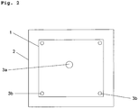
- Fig. 2 shows a preferred embodiment in plan view with a cell 1, an underlying cover layer 2, a centrally located localized contact element with adhesive properties 3a to the preceding cover layer, and four localized contact elements with sliding properties 3b.
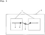
- Fig. 3 shows a preferred embodiment, in which the cell connector 4 is provided between its first connection point 5 to the cell and the adhesive element 3 with a (here arcuate) expansion element.
- the cell connector 4 is fixed on a cover layer 2 via the adhesive element 3.
- the adhesive element 3 can at the same time space the two cover layers and / or can firmly connect the two cover layers with one another, so that a stiffening of the composite takes place.
- the localized contact element with adhesive properties between cell connector and cover layer can also be used in the Be arranged area of the cell.
- it may additionally coincide with a junction between cell connector and cell.
- variant A a local contact element 11 is first shown in variant A, which has adhesive properties at both ends and thus allows a material connection with the cover layers.
- variant B shows a local contact element, which has on one side a sliding bearing 12 and on the other side a materially connected fixed bearing 13. It is advantageous if the cross section of the local contact element tapers towards the sliding bearing 12.
- variant C represents a local contact element with a fixed bearing 13 at both ends, in which a solar cell or a cell connector 14 is integrated.
- variant D differs from variant C in that the local contact element has a sliding bearing 12 on one surface.
- variant E differs from the variant D in that here the localized contact element has two sliding surfaces.
- variant F the solar cell or a cell connector 14 is fastened by means of a local contact element 11 to a cover layer, wherein the local contact element has fixed bearings on both sides.
- Variants G1 and G2 differ from variant F in that in this case the localized contact element has a sliding bearing 12 towards the cover layer or to the solar cell or to the cell connector.
Landscapes
- Photovoltaic Devices (AREA)
Description
- Die Erfindung betrifft ein photovoltaisches Modul enthaltend eine erste und eine zweite Deckschicht, eine zwischen diesen befindliche Anordnung von über Zellverbindern verbundenen photovoltaischen Zellen sowie eine das photovoltaische Modul umlaufende Randabdichtung der Deckschichten. Das erfindungsgemäße Modul ermöglicht dabei eine Minimierung der mechanischen Belastungen, z.B. durch unterschiedliche thermische Ausdehnungskoeffizienten, der photovoltaischen Zellen. Ebenso wird ein Verfahren zur Herstellung der erfindungsgemäßen photovoltaischen Module bereitgestellt.
- Wafer-basierte Solarzellen müssen zwischen schützenden Deckschichten angeordnet werden. Ihre Fixierung muss die unterschiedlichen thermischen Ausdehnungskoeffizienten zwischen Deckschichtmaterialien, insbesondere Glas, und dem Wafermaterial, Silizium, berücksichtigen. Schließlich muss der Produktionsprozess des Solarmoduls wirtschaftlichen Anforderungen bezüglich Material- und Verarbeitungskosten genügen.
- Im Stand der Technik wird diese Aufgabe durch ein Einkapselungsmaterial gelöst, das die Zellen beidseitig umschließt und mit den Deckschichten aus Glas bzw. Rückseitenfolien/Glas verbindet. Die Zellen werden vor der Einkapselung elektrisch in Serie verbunden, so dass Zellstrings und schließlich eine Zellmatrix entstehen.
- Nachteil des Verfahrens ist ein erhöhter Materialaufwand, eine Verzögerung des Produktionsprozesses durch den Laminierschritt und ein erhöhtes Bruchrisiko der Zellen im Modul beim Einsatz dünner Wafer.
- Die Lehre der
WO 2004/095586 verzichtet auf die Einkapselung zugunsten einer Zellfixierung durch Vakuum-Andruck zwischen den Deckschichten und einer nur randseitigen Abdichtung. Hier sind die Fragen der Beständigkeit des Vakuums sowie der Kontaktstellen zwischen Glas, Zellen und Zellverbinder noch ungeklärt. - Die
DE 197 52 678 A1 beschreibt eine Ausführung ohne Einkapselungsmaterial, bei der die Zellen punktuell an der Deckschicht fixiert sind. Die Mindestbeabstandung der beiden Deckschichten wird nicht beschrieben. Weiterhin müssen die Fixierungsstellen aufgrund der unterschiedlichen thermischen Ausdehnungskoeffizienten zwischen Zellen und Glas eine Dicke aufweisen, die die Wärmeabgabe der Zellen behindert. - Die
JP 57-172777 A - Ausgehend hiervon war es Aufgabe der vorliegenden Erfindung, die aus dem Stand der Technik bekannten Nachteile zu beseitigen und photovoltaische Module bereitzustellen, die eine minimale mechanische Belastung der photovoltaischen Zellen ermöglichen und dabei den hierfür erforderlichen Herstellungsaufwand zu reduzieren.
- Diese Aufgabe wird durch das photovoltaische Modul mit den Merkmalen des Anspruchs 1 sowie durch das Verfahren zu dessen Herstellung mit den Merkmalen des Anspruchs 14 gelöst. Die weiteren abhängigen Ansprüche zeigen vorteilhafte Weiterbildungen auf.
- Erfindungsgemäß wird ein photovoltaisches Modul bereitgestellt, das eine erste und eine zweite Deckschicht, eine zwischen diesen befindliche Anordnung von über Zellverbindern verbundenen photovoltaischen Zellen sowie eine das photovoltaische Modul umlaufende Randabdichtung der Deckschichten aufweist. Das photovoltaische Modul weist dabei mindestens ein erstes und ein zweites lokalisiertes Kontaktelement (LKE) auf, welche die beiden Deckschichten beabstanden. Weiterhin ist mindestens eine photovoltaische Zelle oder mindestens ein Zellverbinder über das mindestens eine erste LKE mit mindestens einer Deckschicht stoffschlüssig verbunden. Ein weiteres Merkmal des erfindungsgemäßen Moduls ist es, dass mindestens eine photovoltaische Zelle das mindestens eine zweite LKE stoffschlüssig verbunden und/oder in Gleitkontakt angeordnet aufweist zur Beabstandung zu mindestens einer Deckschicht.
- Die erfindungsgemäße Lösung beschreibt einen Modulaufbau, wobei im Gegensatz zum Stand der Technik auf eine volumenfüllende Einkapselung zwischen den Deckschichten verzichtet wird. Vielmehr erfolgt ein punk tueller Einsatz von Material (sog. lokalisierte Kontaktelemente, LKE) zur Fixierung, Beabstandung und gegebenenfalls Aussteifung, bei einem ansonsten gasgefüllten, randseitig abgedichteten Modul.
- Die Erfindung basiert auf dem Grundgedanken, die Zellen über jeweils maximal eine starre Anbindung so zu fixieren, dass thermische Ausdehnungsunterschiede zwischen Zelle und Deckschicht nicht zu kritischen Spannungen führen. Dies kann beispielsweise durch eine einzelne Haftstelle zwischen photovoltaischer Zelle und Deckschicht realisiert werden, wobei der Rest der Zellfläche in tangentialer Richtung frei beweglich ist.
- Erfindungsgemäß weist das mindestens eine zweite LKE ein Gleitlager zur Herstellung eines Gleitkontaktes mit Deckschichten und ein Festlager zur stoffschlüssigen Verbindung der mindestens einen Deckschicht mit der mindestens einen photovoltaischen Zelle auf. Die stoffschlüssige Verbindung der Festlager basiert dabei vorzugsweise auf physikalischen und/oder chemischen Wechselwirkungen. Hierzu zählen beispielsweise Klebe-, Löt- oder Schweißverbindungen.
- Für ein lokales Kontaktelement, das ein Gleitlager aufweist, ist es bevorzugt, wenn sich der Querschnitt des LKE zum Gleitlager hin verjüngt. Dies ermöglicht eine gewisse Beweglichkeit des lokalen Kontaktelements.
- Das lokalisierte Kontaktelement besteht oder enthält vorzugsweise ein organisches oder anorganisches Elastomer, z.B. auch ein geschäumtes Material, zum Ausgleich von Abstandsänderungen zwischen den Deckschichten.
- Das lokalisierte Kontaktelement weist vorzugsweise eine Dicke im Bereich von 0,001 bis 5 mm, bevorzugt von 0,01 bis 0,5 mm und besonders bevorzugt von 0,1 bis 0,3 mm auf.
- Das lokalisierte Kontaktelement kann dabei vorzugsweise mit beiden Deckschichten und einer photovoltaischen Zelle oder, in einer weiteren bevorzugten Ausführungsform, mit beiden Deckschichten und einem Zellverbindern in Verbindung stehen.
- Die flächige Ausdehnung der LKE auf der photovoltaischen Zelle macht einen Flächenanteil von ≤ 10 %, bevorzugt ≤ 5 % und besonders bevorzugt ≤ 2 % der photovoltaischen Zelle aus.
- Es ist weiterhin bevorzugt, dass die erste Deckschicht und die lokalisierten Kontaktelemente, die zwischen der ersten Deckschicht und den photovoltaischen Zellen liegen, im Wellenlängenbereich von 300 bis 1200 nm im Wesentlichen transparent sind, so dass Sonnenstrahlung ungestört auf die Solarzellen treffen kann.
- Die Zellverbinder zwischen den photovoltaischen Zellen sind vorzugsweise elektrisch und mechanisch mit den photovoltaischen Zellen verbunden. Hierbei ist es auch möglich, dass der Zellverbinder ein Entspannungselement darstellt, das einen Ausgleich lateraler Bewegungen der photovoltaischen Zellen ermöglicht. Hierzu zählen insbesondere Elemente mit einer zumindest eindimensionalen Federwirkung. Das Entspannungselement kann dabei vorzugsweise bogenförmig, s-förmig und/oder gewinkelt sein.
- Eine weitere bevorzugte Ausführungsform sieht vor, dass ein mit beiden Deckschichten in Kontakt stehendes, lokalisiertes Kontaktelement mit einem Entspannungselement, das über mindestens zwei Verbindungsstellen an mindestens zwei benachbarten Solarzelle angeordnet ist, verbunden ist.
Entspannungselemente, die mit Zellverbindern in Verbindung stehen, verringern Krafteinwirkung auf die photovoltaische Zelle, beispielsweise aufgrund von unterschiedlicher thermischer Ausdehnung oder von Moduldurchbiegung. - Vorzugsweise sind die lokalisierten Kontaktelemente zur Beabstandung der Deckschichten so dimensioniert, dass sie unter üblichen Drucklasten einen unmittelbaren Kontakt der Deckschichten mit den photovoltaischen Zellen verhindern.
- Eine weitere bevorzugte Ausführungsform sieht vor, dass mindestens ein lokalisiertes Kontaktelement einen Zellverbinder mit einer Deckschicht derart verbindet, dass in der näheren Umgebung des Angriffspunktes am Zellverbinder keine stoffschlüssige Verbindung zwischen Zellverbinder und photovoltaischer Zelle besteht.
- Grundsätzlich weist das erfindungsgemäße photovoltaische Modul somit unterschiedliche lokalisierte Kontaktelemente auf, die sich hinsichtlich der Art des Kontaktes mit den anderen Bauelementen unterscheiden.
- Für die Fixierung kann das lokalisierte Kontaktelement ein beidseitig haftendes Element oder eine reine Klebemasse sein, die schlüssige Verbindungen zwischen Zelle und Deckschicht erzeugt. Die Haftstelle(n) befinden sich innerhalb eines kleinen, kompakten Flächenausschnitts, wodurch sich Unterschiede im thermischen Ausdehnungskoeffizienten zwischen Zelle und Deckschicht auch mit sehr dünnen Klebstoff-Schichten ausgleichen lassen.
- Eine zweite Variante des als Haftelement ausgestalteten lokalisierten Kontaktelementes betrifft Verbindungen von Zellverbinder und Deckschicht.
- Die lokalisierten Kontaktelemente, deren Funktion die Beabstandung der Deckschichten ist, weisen Gleitstellen- und/oder Haftstellen auf. Sind derartige lokalisierte Kontaktelemente im Bereich einer photovoltaischen Zelle angeordnet, so kann eine Gleitstelle auf der gegenüber liegenden Seite zur Haftstelle vorgesehen werden. So wird sichergestellt, dass die photovoltaische Zelle bei geringer Verformung/Verlagerung der Deckschichten nur senkrechte Druckkräfte erfährt, wodurch keine nennenswerten Scherkräfte auftreten.
- Sind die zur Beabstandung der Deckschichten lokalisierten Kontaktelemente im Bereich zwischen den photovoltaischen Zellen angeordnet, so kann eine Gleit- oder Haftstelle direkt zwischen beiden Deckschichten ausgebildet sein. Durch Haftstellen lässt sich der Verbund der Deckschichten zusätzlich aussteifen, bei reinen Gleitstellen bleibt der Verbund hingegen statisch lose.
- Bevorzugt ist eine Fixierung der Zellen in geringem Abstand zur ersten Deckschicht, um die Wärmeabgabe zu erleichtern.
- Für die Leistung des Moduls ist es vorteilhaft,
- die Zellen mit einem geringen Abstand zu den Deckschichten, insbesondere zu der oberen Deckschicht anzuordnen, weil die Wärme dann besser nach außen durchgeleitet wird und die Zelltemperatur niedriger bleibt,
- die obere Deckschicht beidseitig mit reflexionsmindernden Eigenschaften (Beschichtung, Strukturierung) zu versehen,
- die Zellen gegen Gas, d.h. ein Medium mit Brechungsindex 1 zu entspiegeln.
- Erfindungsgemäß wird ebenso ein Verfahren zur Herstellung eines photovoltaischen Moduls, wie es zuvor beschrieben wurde, bereitgestellt, bei dem die lokalisierten Kontaktelemente in flüssiger oder pastöser Form auf mindestens einer Deckschicht und mindestens einer photovoltaischen Zelle aufgebracht und anschließend thermisch oder photochemisch ausgehärtet werden. Die lokalisierten Kontaktelemente in flüssiger bzw. pastöser Form werden dabei vorzugsweise gedruckt, gesprüht und/oder dosiert.
- Anhand der nachfolgenden Figuren soll der erfindungsgemäße Gegenstand näher erläutert werden, ohne diesen auf die hier gezeigten speziellen Ausführungsformen einschränken zu wollen.
-
Fig. 1 zeigt eine erfindungsgemäße Variante im Querschnitt. -
Fig. 2 zeigt eine erfindungsgemäße Variante in Aufsicht. -
Fig. 3 zeigt eine weitere erfindungsgemäße Variante in Aufsicht. -
Fig. 4 zeigt in einer schematischen Darstellung verschiedene Varianten für lokalisierte Kontaktelemente, die in einem einzigen System integriert sind. -
Fig. 1 zeigt eine bevorzugte Ausführung im Querschnitt mit einer Zelle 1, den Deckschichten 2a und 2b, einem lokalisierten Kontaktelement mit Hafteigenschaften 3a und einem lokalisierten Kontaktelement mit Gleiteigenschaften 3b. Das Gleitelement liegt hinter dem Haftelement und überträgt dadurch Drucklasten zwischen den Deckschichten senkrecht zur Zellfläche. Durch die Gleitfläche werden Scherspannungen an der Zelle vermieden. - Das lokalisierte Kontaktelement mit Hafteigenschaften 3a kann als trägerloser Klebefilm ausgebildet sein, das lokalisierte Kontaktelement mit Gleiteigenschaften 3b als geschäumtes Polymer mit einseitig angeordneter Klebeschicht.
-
Fig. 2 zeigt eine bevorzugte Ausführung in Aufsicht mit einer Zelle 1, einer dahinter liegenden Deckschicht 2, einem zentral angeordneten lokalisierten Kontaktelement mit Hafteigenschaften 3a zur davor liegenden Deckschicht, sowie vier lokalisierten Kontaktelementen mit Gleiteigenschaften 3b. -
Fig. 3 zeigt eine bevorzugte Ausführung, bei der der Zellverbinder 4 zwischen seiner ersten Verbindungsstelle 5 zur Zelle und dem Haftelement 3 mit einem (hier bogenförmigem) Entspannungselement versehen ist. Der Zellverbinder 4 ist über das Haftelement 3 auf einer Deckschicht 2 fixiert. Das Haftelement 3 kann gleichzeitig die beiden Deckschichten beabstanden und/oder kann die beiden Deckschichten miteinander fest verbinden, so dass eine Aussteifung des Verbundes erfolgt. - Das lokalisierte Kontaktelement mit Hafteigenschaften zwischen Zellverbinder und Deckschicht kann auch im Bereich der Zelle angeordnet sein. Optional kann es zusätzlich mit einer Verbindungsstelle zwischen Zellverbinder und Zelle zusammenfallen.
- In
Fig. 4 sind verschiedene Varianten für die Anordnung lokalisierter Kontaktelemente dargestellt. Zwischen den Deckschichten 10 und 10' ist in der Variante A zunächst ein lokales Kontaktelement 11 dargestellt, das an beiden Enden Hafteigenschaften besitzt und so eine stoffschlüssige Verbindung mit den Deckschichten ermöglicht. Die Variante B zeigt ein lokales Kontaktelement, das auf der einen Seite ein Gleitlager 12 und auf der anderen Seite ein stoffschlüssig verbundenes Festlager 13 aufweist. Dabei ist es vorteilhaft, wenn sich der Querschnitt des lokalen Kontaktelementes zum Gleitlager 12 hin verjüngt. Die Variante C stellt ein lokales Kontaktelement mit Festlager 13 an beiden Enden dar, in das eine Solarzelle oder ein Zellverbinder 14 integriert ist. Die Variante D unterscheidet sich von der Variante C dadurch, dass das lokale Kontaktelement an der einen Oberfläche ein Gleitlager 12 aufweist. Die Variante E unterscheidet sich von der Variante D dadurch, dass hier das lokalisierte Kontaktelement zwei Gleitflächen aufweist. In der Variante F ist die Solarzelle oder ein Zellverbinder 14 mittels eines lokalen Kontaktelementes 11 an einer Deckschicht befestigt, wobei das lokale Kontaktelement an beiden Seiten Festlager aufweist. Die Varianten G1 und G2 unterscheiden sich von der Variante F dadurch, dass hier das lokalisierte Kontaktelement zur Deckschicht bzw. zur Solarzelle oder zum Zellverbinder hin ein Gleitlager 12 aufweist.
Claims (14)
- Photovoltaisches Modul enthaltend eine erste und eine zweite Deckschicht (2a, 2b), eine zwischen diesen befindliche Anordnung von über Zellverbindern (4) verbundenen photovoltaischen Zellen (1) sowie eine das photovoltaische Modul umlaufende Randabdichtung der Deckschichten,
wobei das Modul mindestens ein erstes und ein zweites lokalisiertes Kontaktelement (LKE)(3a, 3b) aufweist, welche die beiden Deckschichten (2a, 2b) beabstanden,
mindestens eine photovoltaische Zelle (1) oder mindestens ein Zellverbinder (4) über das mindestens eine erste LKE (3a) mit mindestens einer Deckschicht (2a, 2b) stoffschlüssig verbunden ist und dass mindestens eine photovoltaische Zelle (1) das mindestens eine zweite LKE (3b) stoffschlüssig verbunden oder in Gleitkontakt angeordnet aufweist zur Beabstandung zu mindestens einer Deckschicht (2a, 2b), dadurch gekennzeichnet, dass
die flächige Ausdehnung der LKE (3a, 3b) auf der photovoltaischen Zelle (1) einen Flächenanteil von ≤ 10 % der photovoltaischen Zelle ausmacht und dass
das mindestens eine zweite LKE (3b)i) ein Gleitlager (12) zur Herstellung eines Gleitkontaktes mit der mindestens einen Deckschicht (2a, 2b) oder mit der mindestens einen photovoltaischen Zelle (1); undii) ein Festlager (13) zur stoffschlüssigen Verbindung mit der mindestens einen Deckschicht (2a, 2b) oder mit der mindestens einen photovoltaischen Zelle (1);aufweist. - Photovoltaisches Modul nach einem der vorhergehenden Ansprüche, dadurch gekennzeichnet, dass die stoffschlüssigen Verbindung des Festlagers (13) auf physikalischen und/oder chemischen Wechselwirkungen basiert, insbesondere eine Klebe-, ein Löt- oder eine Schweißverbindung ist.
- Photovoltaisches Modul nach einem der vorhergehenden Ansprüche, dadurch gekennzeichnet, dass die LKE (3a, 3b) aus einem organischen oder anorganischen Elastomer, bevorzugt einem geschäumten Material, zum Ausgleich von Abstandsänderungen zwischen den Deckschichten (2a, 2b) bestehen oder dieses enthalten.
- Photovoltaisches Modul nach einem der vorhergehenden Ansprüche, dadurch gekennzeichnet, dass die LKE (3a, 3b) eine Dicke im Bereich von 0,001 bis 5 mm, bevorzugt von 0,01 bis 0,5 mm und besonders bevorzugt von 0,1 bis 0,3 mm aufweisen.
- Photovoltaisches Modul nach einem der vorhergehenden Ansprüche, dadurch gekennzeichnet, dass mindestens eines der LKE (3a, 3b) mit beiden Deckschichten (2a, 2b) und einer photovoltaischen Zelle (1) oder einem Zellverbinder (4) in Verbindung steht.
- Photovoltaisches Modul nach einem der vorhergehenden Ansprüche, dadurch gekennzeichnet, dass die flächige Ausdehnung der LKE (3a, 3b) auf der photovoltaischen Zelle (1) einen Flächenanteil ≤ 5% und bevorzugt ≤ 2% der Zelle (1) ausmacht.
- Photovoltaisches Modul nach einem der vorhergehenden Ansprüche, dadurch gekennzeichnet, dass die erste Deckschicht (2a, 2b) und die LKE (3a, 3b), die zwischen der ersten Deckschicht (2a, 2b) und den photovoltaischen Zellen (1) liegen, im Wellenlängenbereich von 300 bis 1200 nm im Wesentlichen transparent sind.
- Photovoltaisches Modul nach einem der vorhergehenden Ansprüche, dadurch gekennzeichnet, dass der Zellverbinder (4) elektrisch und mechanisch mit der photovoltaischen Zelle (1) verbunden ist.
- Photovoltaisches Modul nach einem der vorhergehenden Ansprüche, dadurch gekennzeichnet, dass der Zellverbinder (4) ein Entspannungselement ist, das einen Ausgleich lateraler Bewegungen der photovoltaischen Zellen (1) ermöglicht, insbesondere ein Element mit einer zumindest eindimensionalen Federwirkung, wobei das Entspannungselement bevorzugt bogenförmig, s-förmig und/oder gewinkelt zur Bereitstellung der zumindest eindimensionalen Federwirkung ist.
- Photovoltaisches Modul nach einem der Ansprüche 8 oder 9, dadurch gekennzeichnet, dass mindestens ein mit beiden Deckschichten (2a, 2b) in Kontakt stehendes, lokalisiertes Kontaktelement (11) mit einem Entspannungselement, das über mindestens zwei Verbindungsstellen an mindestens zwei benachbarten Solarzellen (1) angeordnet ist, verbunden ist.
- Photovoltaisches Modul nach einem der vorhergehenden Ansprüche, dadurch gekennzeichnet, dass das mindestens eine zweite lokale Kontaktelement (3b) einen sich zum Gleitlager (12) verjüngenden Querschnitt aufweist.
- Photovoltaisches Modul nach einem der vorhergehenden Ansprüche, dadurch gekennzeichnet, dass die LKE (3a, 3b) zur Beabstandung der Deckschichten (2a, 2b) so dimensioniert sind, dass sie unter üblichen Drucklasten einen unmittelbaren Kontakt der Deckschichten (2a, 2b) mit den photovoltaischen Zellen (1) verhindern.
- Photovoltaisches Modul nach einem der vorhergehenden Ansprüche, dadurch gekennzeichnet, dass das mindestens eine erste LKE (3a) den Zellverbinder (4) mit einer Deckschicht (2a, 2b) derart verbindet, dass in der näheren Umgebung des Angriffspunktes am Zellverbinder (4) keine stoffschlüssige Verbindung zwischen Zellverbinder (4) und photovoltaischer Zelle (1) besteht.
- Verfahren zur Herstellung eines photovoltaischen Moduls nach einem der vorhergehenden Ansprüche, bei dem die lokalisierten Kontaktelemente (3a, 3b) in flüssiger oder pastöser Form auf mindestens einer Deckschicht (2a, 2b) und mindestens einer photovoltaischen Zelle (1) aufgebracht und anschließend thermisch oder photochemisch ausgehärtet werden, wobei die lokalisierten Kontaktelemente (3a, 3b) vorzugsweise gedruckt, gesprüht und/oder dosiert werden.
Applications Claiming Priority (2)
| Application Number | Priority Date | Filing Date | Title |
|---|---|---|---|
| DE102009009036A DE102009009036A1 (de) | 2009-02-16 | 2009-02-16 | Photovoltaisches Modul und Verfahren zu dessen Herstellung |
| PCT/EP2010/000919 WO2010091889A2 (de) | 2009-02-16 | 2010-02-15 | Photovoltaisches modul und verfahren zu dessen herstellung |
Publications (2)
| Publication Number | Publication Date |
|---|---|
| EP2396827A2 EP2396827A2 (de) | 2011-12-21 |
| EP2396827B1 true EP2396827B1 (de) | 2017-12-27 |
Family
ID=42356550
Family Applications (1)
| Application Number | Title | Priority Date | Filing Date |
|---|---|---|---|
| EP10705545.1A Active EP2396827B1 (de) | 2009-02-16 | 2010-02-15 | Photovoltaisches modul und verfahren zu dessen herstellung |
Country Status (6)
| Country | Link |
|---|---|
| US (1) | US20120037212A1 (de) |
| EP (1) | EP2396827B1 (de) |
| CN (1) | CN102396077B (de) |
| DE (1) | DE102009009036A1 (de) |
| ES (1) | ES2661544T3 (de) |
| WO (1) | WO2010091889A2 (de) |
Families Citing this family (7)
| Publication number | Priority date | Publication date | Assignee | Title |
|---|---|---|---|---|
| KR101128568B1 (ko) * | 2010-07-14 | 2012-03-23 | 삼성전기주식회사 | 태양전지 모듈 및 그 제조 방법, 그리고 상기 태양전지 모듈을 구비하는 모바일 장치 및 그 제조 방법 |
| DE102011012582A1 (de) * | 2011-02-28 | 2012-08-30 | Fraunhofer-Gesellschaft zur Förderung der angewandten Forschung e.V. | Photovoltaisches Modul und Verfahren zu dessen Herstellung |
| DE102011112286A1 (de) * | 2011-09-05 | 2013-03-07 | Henze-Glas GmbH | Isolierglasscheibe |
| DE102011114396A1 (de) | 2011-09-20 | 2013-03-21 | Solon Se | Verfahren zur elektrischen Reihenverschaltung von Solarzellen |
| DE202012100789U1 (de) | 2012-03-06 | 2013-03-08 | Sitec Solar Gmbh | Photovoltaisches Modul |
| DE102013103185B4 (de) * | 2013-03-28 | 2016-09-15 | Henze-Glas GmbH | Isolierglasscheibe mit einem Solarmodul zur Erzeugung elektrischer Energie |
| DE102023115468A1 (de) * | 2023-06-14 | 2024-12-19 | Sunmaxx PVT GmbH | Photovoltaik-thermisches Modul und Solarsystem |
Family Cites Families (9)
| Publication number | Priority date | Publication date | Assignee | Title |
|---|---|---|---|---|
| JPS57172777A (en) * | 1981-04-15 | 1982-10-23 | Nippon Sheet Glass Co Ltd | Modularization of photocell |
| DE3801989A1 (de) * | 1988-01-23 | 1989-07-27 | Licentia Gmbh | Isolierglasscheibe |
| DE4128766C2 (de) * | 1991-08-29 | 1995-07-20 | Flachglas Ag | Solarmodul sowie Verfahren zu dessen Herstellung |
| DE19752678A1 (de) | 1997-11-28 | 1999-06-02 | Inst Solarenergieforschung | Verfahren zur Herstellung eines Photovoltaik Moduls und Photovoltaik Modul |
| WO2004095586A2 (fr) | 2003-04-16 | 2004-11-04 | Apollon Solar | Module photovoltaique et procede de fabrication d’un tel module |
| DE10356690B4 (de) * | 2003-07-05 | 2008-07-03 | Pvflex Solar Gmbh | Flexibles Solarmodul zur Dachintegration mit kristallinen Siliziumzellen |
| EP2106619A2 (de) * | 2006-12-22 | 2009-10-07 | Paul M. Adriani | Strukturen für günstige, zuverlässige solarmodule |
| EP2109894A2 (de) * | 2007-01-31 | 2009-10-21 | Renewable Energy Corporation ASA | Verbindungsreflektorband für solarzellenmodule |
| EP1959502A1 (de) * | 2007-02-14 | 2008-08-20 | Imphy Alloys | Photovoltaikmodul und Module zur Energie- oder Lichterzeugung |
-
2009
- 2009-02-16 DE DE102009009036A patent/DE102009009036A1/de not_active Withdrawn
-
2010
- 2010-02-15 US US13/138,422 patent/US20120037212A1/en not_active Abandoned
- 2010-02-15 WO PCT/EP2010/000919 patent/WO2010091889A2/de not_active Ceased
- 2010-02-15 ES ES10705545.1T patent/ES2661544T3/es active Active
- 2010-02-15 EP EP10705545.1A patent/EP2396827B1/de active Active
- 2010-02-15 CN CN201080016969.8A patent/CN102396077B/zh active Active
Also Published As
| Publication number | Publication date |
|---|---|
| DE102009009036A1 (de) | 2010-08-26 |
| WO2010091889A3 (de) | 2011-07-07 |
| CN102396077B (zh) | 2016-07-06 |
| US20120037212A1 (en) | 2012-02-16 |
| WO2010091889A2 (de) | 2010-08-19 |
| EP2396827A2 (de) | 2011-12-21 |
| CN102396077A (zh) | 2012-03-28 |
| ES2661544T3 (es) | 2018-04-02 |
Similar Documents
| Publication | Publication Date | Title |
|---|---|---|
| EP2396827A2 (de) | Photovoltaisches modul und verfahren zu dessen herstellung | |
| EP3970210B1 (de) | Verfahren zur herstellung eines ein trägersubstrat aufweisenden displays, ein nach diesem verfahren hergestelltes trägersubstrat sowie ein für ein flexibles display bestimmtes deckglas | |
| WO2003034467A2 (de) | Leistungshalbleitermodul | |
| EP2257142A1 (de) | Befestigung eines Bauelementes an einem Substrat und/oder eines Anschlusselementes an dem Bauelement oder an dem Substrat durch Drucksinterung | |
| WO2011012371A1 (de) | Verfahren zur herstellung eines bauteils mit mindestens einem organischen material und bauteil mit mindestens einem organischen material | |
| DE60304597T2 (de) | Transparentes fenster mit nichttransparenter kontaktfläche für l t-bond-verbindung | |
| EP2938486A1 (de) | Verbundglas | |
| WO2009021475A1 (de) | Glasdeckel oder glasfestelement für ein fahrzeugdach sowie verfahren zur herstellung eines glasdeckels oder glasfestelements | |
| EP2586059A1 (de) | Eingekapseltes steuerungsmodul für ein kraftfahrzeug | |
| DE102019103516B3 (de) | Glasverbundeinheit und Verwendung einer Glasverbundeinheit als funktionelles Element eines Gebäudes | |
| DE102018202263A1 (de) | Batterie für ein Kraftfahrzeug | |
| DE202022103900U1 (de) | Zellverbinder für ein Zellkontaktierungssystem sowie Energiespeicher | |
| DE202022103898U1 (de) | Platinenanordnung sowie Energiespeicher | |
| DE102017214347B4 (de) | Verfahren zur Herstellung eines Fassadenelements sowie Fassadenelement | |
| DE102008013522B4 (de) | Solarmodul mit Glas-Substrat, Polymer-Versiegelungselement und im Substratrandbereich angeordneter Dichtungseinrichtung | |
| DE112020003216T5 (de) | Zugentlastung für Flexfolie | |
| WO2009049613A2 (de) | Aktorisch wirksames und/oder sensitives element, verfahren zu seiner herstellung sowie seine verwendung | |
| DE102007004893B4 (de) | Piezoelektrischer Vielschichtaktor und Verfahren zu seiner Herstellung | |
| DE102008012281B4 (de) | Verfahren zur Herstellung eines Piezo-Aktuators mit auf einem Träger angeordneten Piezo-Elementen | |
| DE102014208529B4 (de) | Kühlereinheit zur Verwendung in einem Batteriemodul, Batteriemodul, Verfahren zu deren Herstellung und Fahrzeug mit Batteriemodul | |
| EP2681773B1 (de) | Photovoltaisches modul und verfahren zu dessen herstellung | |
| EP2811239B1 (de) | Distanzhalter | |
| DE102011083423A1 (de) | Kontaktfederanordnung und Verfahren zur Herstellung derselben | |
| DE202022103899U1 (de) | Zellkontaktierungssystem sowie Energiespeicher | |
| EP1062674B1 (de) | Glastastatur, sowie verfahren zur herstellung einer glastastatur |
Legal Events
| Date | Code | Title | Description |
|---|---|---|---|
| PUAI | Public reference made under article 153(3) epc to a published international application that has entered the european phase |
Free format text: ORIGINAL CODE: 0009012 |
|
| 17P | Request for examination filed |
Effective date: 20110916 |
|
| AK | Designated contracting states |
Kind code of ref document: A2 Designated state(s): AT BE BG CH CY CZ DE DK EE ES FI FR GB GR HR HU IE IS IT LI LT LU LV MC MK MT NL NO PL PT RO SE SI SK SM TR |
|
| DAX | Request for extension of the european patent (deleted) | ||
| 17Q | First examination report despatched |
Effective date: 20120730 |
|
| GRAP | Despatch of communication of intention to grant a patent |
Free format text: ORIGINAL CODE: EPIDOSNIGR1 |
|
| STAA | Information on the status of an ep patent application or granted ep patent |
Free format text: STATUS: GRANT OF PATENT IS INTENDED |
|
| RIC1 | Information provided on ipc code assigned before grant |
Ipc: H01L 31/048 20140101ALI20170710BHEP Ipc: H01L 31/05 20140101AFI20170710BHEP |
|
| INTG | Intention to grant announced |
Effective date: 20170803 |
|
| GRAS | Grant fee paid |
Free format text: ORIGINAL CODE: EPIDOSNIGR3 |
|
| GRAA | (expected) grant |
Free format text: ORIGINAL CODE: 0009210 |
|
| STAA | Information on the status of an ep patent application or granted ep patent |
Free format text: STATUS: THE PATENT HAS BEEN GRANTED |
|
| AK | Designated contracting states |
Kind code of ref document: B1 Designated state(s): AT BE BG CH CY CZ DE DK EE ES FI FR GB GR HR HU IE IS IT LI LT LU LV MC MK MT NL NO PL PT RO SE SI SK SM TR |
|
| REG | Reference to a national code |
Ref country code: GB Ref legal event code: FG4D Free format text: NOT ENGLISH |
|
| REG | Reference to a national code |
Ref country code: CH Ref legal event code: EP |
|
| REG | Reference to a national code |
Ref country code: AT Ref legal event code: REF Ref document number: 958998 Country of ref document: AT Kind code of ref document: T Effective date: 20180115 |
|
| REG | Reference to a national code |
Ref country code: IE Ref legal event code: FG4D Free format text: LANGUAGE OF EP DOCUMENT: GERMAN |
|
| REG | Reference to a national code |
Ref country code: FR Ref legal event code: PLFP Year of fee payment: 9 |
|
| REG | Reference to a national code |
Ref country code: DE Ref legal event code: R096 Ref document number: 502010014506 Country of ref document: DE |
|
| REG | Reference to a national code |
Ref country code: ES Ref legal event code: FG2A Ref document number: 2661544 Country of ref document: ES Kind code of ref document: T3 Effective date: 20180402 |
|
| PG25 | Lapsed in a contracting state [announced via postgrant information from national office to epo] |
Ref country code: NO Free format text: LAPSE BECAUSE OF FAILURE TO SUBMIT A TRANSLATION OF THE DESCRIPTION OR TO PAY THE FEE WITHIN THE PRESCRIBED TIME-LIMIT Effective date: 20180327 Ref country code: LT Free format text: LAPSE BECAUSE OF FAILURE TO SUBMIT A TRANSLATION OF THE DESCRIPTION OR TO PAY THE FEE WITHIN THE PRESCRIBED TIME-LIMIT Effective date: 20171227 Ref country code: FI Free format text: LAPSE BECAUSE OF FAILURE TO SUBMIT A TRANSLATION OF THE DESCRIPTION OR TO PAY THE FEE WITHIN THE PRESCRIBED TIME-LIMIT Effective date: 20171227 |
|
| REG | Reference to a national code |
Ref country code: NL Ref legal event code: MP Effective date: 20171227 |
|
| REG | Reference to a national code |
Ref country code: LT Ref legal event code: MG4D |
|
| PG25 | Lapsed in a contracting state [announced via postgrant information from national office to epo] |
Ref country code: LV Free format text: LAPSE BECAUSE OF FAILURE TO SUBMIT A TRANSLATION OF THE DESCRIPTION OR TO PAY THE FEE WITHIN THE PRESCRIBED TIME-LIMIT Effective date: 20171227 Ref country code: GR Free format text: LAPSE BECAUSE OF FAILURE TO SUBMIT A TRANSLATION OF THE DESCRIPTION OR TO PAY THE FEE WITHIN THE PRESCRIBED TIME-LIMIT Effective date: 20180328 Ref country code: BG Free format text: LAPSE BECAUSE OF FAILURE TO SUBMIT A TRANSLATION OF THE DESCRIPTION OR TO PAY THE FEE WITHIN THE PRESCRIBED TIME-LIMIT Effective date: 20180327 Ref country code: HR Free format text: LAPSE BECAUSE OF FAILURE TO SUBMIT A TRANSLATION OF THE DESCRIPTION OR TO PAY THE FEE WITHIN THE PRESCRIBED TIME-LIMIT Effective date: 20171227 |
|
| PG25 | Lapsed in a contracting state [announced via postgrant information from national office to epo] |
Ref country code: NL Free format text: LAPSE BECAUSE OF FAILURE TO SUBMIT A TRANSLATION OF THE DESCRIPTION OR TO PAY THE FEE WITHIN THE PRESCRIBED TIME-LIMIT Effective date: 20171227 |
|
| PG25 | Lapsed in a contracting state [announced via postgrant information from national office to epo] |
Ref country code: CZ Free format text: LAPSE BECAUSE OF FAILURE TO SUBMIT A TRANSLATION OF THE DESCRIPTION OR TO PAY THE FEE WITHIN THE PRESCRIBED TIME-LIMIT Effective date: 20171227 Ref country code: SK Free format text: LAPSE BECAUSE OF FAILURE TO SUBMIT A TRANSLATION OF THE DESCRIPTION OR TO PAY THE FEE WITHIN THE PRESCRIBED TIME-LIMIT Effective date: 20171227 Ref country code: EE Free format text: LAPSE BECAUSE OF FAILURE TO SUBMIT A TRANSLATION OF THE DESCRIPTION OR TO PAY THE FEE WITHIN THE PRESCRIBED TIME-LIMIT Effective date: 20171227 Ref country code: CY Free format text: LAPSE BECAUSE OF FAILURE TO SUBMIT A TRANSLATION OF THE DESCRIPTION OR TO PAY THE FEE WITHIN THE PRESCRIBED TIME-LIMIT Effective date: 20171227 |
|
| PG25 | Lapsed in a contracting state [announced via postgrant information from national office to epo] |
Ref country code: IS Free format text: LAPSE BECAUSE OF FAILURE TO SUBMIT A TRANSLATION OF THE DESCRIPTION OR TO PAY THE FEE WITHIN THE PRESCRIBED TIME-LIMIT Effective date: 20180427 Ref country code: RO Free format text: LAPSE BECAUSE OF FAILURE TO SUBMIT A TRANSLATION OF THE DESCRIPTION OR TO PAY THE FEE WITHIN THE PRESCRIBED TIME-LIMIT Effective date: 20171227 Ref country code: SM Free format text: LAPSE BECAUSE OF FAILURE TO SUBMIT A TRANSLATION OF THE DESCRIPTION OR TO PAY THE FEE WITHIN THE PRESCRIBED TIME-LIMIT Effective date: 20171227 Ref country code: PL Free format text: LAPSE BECAUSE OF FAILURE TO SUBMIT A TRANSLATION OF THE DESCRIPTION OR TO PAY THE FEE WITHIN THE PRESCRIBED TIME-LIMIT Effective date: 20171227 |
|
| REG | Reference to a national code |
Ref country code: CH Ref legal event code: PL |
|
| PG25 | Lapsed in a contracting state [announced via postgrant information from national office to epo] |
Ref country code: MC Free format text: LAPSE BECAUSE OF FAILURE TO SUBMIT A TRANSLATION OF THE DESCRIPTION OR TO PAY THE FEE WITHIN THE PRESCRIBED TIME-LIMIT Effective date: 20171227 Ref country code: MT Free format text: LAPSE BECAUSE OF FAILURE TO SUBMIT A TRANSLATION OF THE DESCRIPTION OR TO PAY THE FEE WITHIN THE PRESCRIBED TIME-LIMIT Effective date: 20171227 |
|
| REG | Reference to a national code |
Ref country code: DE Ref legal event code: R097 Ref document number: 502010014506 Country of ref document: DE |
|
| PLBE | No opposition filed within time limit |
Free format text: ORIGINAL CODE: 0009261 |
|
| STAA | Information on the status of an ep patent application or granted ep patent |
Free format text: STATUS: NO OPPOSITION FILED WITHIN TIME LIMIT |
|
| GBPC | Gb: european patent ceased through non-payment of renewal fee |
Effective date: 20180327 |
|
| REG | Reference to a national code |
Ref country code: IE Ref legal event code: MM4A |
|
| REG | Reference to a national code |
Ref country code: BE Ref legal event code: MM Effective date: 20180228 |
|
| PG25 | Lapsed in a contracting state [announced via postgrant information from national office to epo] |
Ref country code: DK Free format text: LAPSE BECAUSE OF FAILURE TO SUBMIT A TRANSLATION OF THE DESCRIPTION OR TO PAY THE FEE WITHIN THE PRESCRIBED TIME-LIMIT Effective date: 20171227 Ref country code: LI Free format text: LAPSE BECAUSE OF NON-PAYMENT OF DUE FEES Effective date: 20180228 Ref country code: CH Free format text: LAPSE BECAUSE OF NON-PAYMENT OF DUE FEES Effective date: 20180228 Ref country code: LU Free format text: LAPSE BECAUSE OF NON-PAYMENT OF DUE FEES Effective date: 20180215 |
|
| 26N | No opposition filed |
Effective date: 20180928 |
|
| PG25 | Lapsed in a contracting state [announced via postgrant information from national office to epo] |
Ref country code: IE Free format text: LAPSE BECAUSE OF NON-PAYMENT OF DUE FEES Effective date: 20180215 |
|
| PG25 | Lapsed in a contracting state [announced via postgrant information from national office to epo] |
Ref country code: SI Free format text: LAPSE BECAUSE OF FAILURE TO SUBMIT A TRANSLATION OF THE DESCRIPTION OR TO PAY THE FEE WITHIN THE PRESCRIBED TIME-LIMIT Effective date: 20171227 Ref country code: BE Free format text: LAPSE BECAUSE OF NON-PAYMENT OF DUE FEES Effective date: 20180228 Ref country code: GB Free format text: LAPSE BECAUSE OF NON-PAYMENT OF DUE FEES Effective date: 20180327 |
|
| REG | Reference to a national code |
Ref country code: AT Ref legal event code: MM01 Ref document number: 958998 Country of ref document: AT Kind code of ref document: T Effective date: 20180215 |
|
| PG25 | Lapsed in a contracting state [announced via postgrant information from national office to epo] |
Ref country code: AT Free format text: LAPSE BECAUSE OF NON-PAYMENT OF DUE FEES Effective date: 20180215 |
|
| PG25 | Lapsed in a contracting state [announced via postgrant information from national office to epo] |
Ref country code: TR Free format text: LAPSE BECAUSE OF FAILURE TO SUBMIT A TRANSLATION OF THE DESCRIPTION OR TO PAY THE FEE WITHIN THE PRESCRIBED TIME-LIMIT Effective date: 20171227 |
|
| PG25 | Lapsed in a contracting state [announced via postgrant information from national office to epo] |
Ref country code: PT Free format text: LAPSE BECAUSE OF FAILURE TO SUBMIT A TRANSLATION OF THE DESCRIPTION OR TO PAY THE FEE WITHIN THE PRESCRIBED TIME-LIMIT Effective date: 20171227 Ref country code: HU Free format text: LAPSE BECAUSE OF FAILURE TO SUBMIT A TRANSLATION OF THE DESCRIPTION OR TO PAY THE FEE WITHIN THE PRESCRIBED TIME-LIMIT; INVALID AB INITIO Effective date: 20100215 |
|
| PG25 | Lapsed in a contracting state [announced via postgrant information from national office to epo] |
Ref country code: MK Free format text: LAPSE BECAUSE OF NON-PAYMENT OF DUE FEES Effective date: 20171227 Ref country code: SE Free format text: LAPSE BECAUSE OF FAILURE TO SUBMIT A TRANSLATION OF THE DESCRIPTION OR TO PAY THE FEE WITHIN THE PRESCRIBED TIME-LIMIT Effective date: 20171227 |
|
| P01 | Opt-out of the competence of the unified patent court (upc) registered |
Effective date: 20230524 |
|
| REG | Reference to a national code |
Ref country code: DE Ref legal event code: R079 Ref document number: 502010014506 Country of ref document: DE Free format text: PREVIOUS MAIN CLASS: H01L0031050000 Ipc: H10F0019900000 |
|
| REG | Reference to a national code |
Ref country code: DE Ref legal event code: R081 Ref document number: 502010014506 Country of ref document: DE Owner name: FLACHGLAS SACHSEN GMBH, DE Free format text: FORMER OWNER: FRAUNHOFER-GESELLSCHAFT ZUR FOERDERUNG DER ANGEWANDTEN FORSCHUNG E.V., 80686 MUENCHEN, DE |
|
| REG | Reference to a national code |
Ref country code: DE Ref legal event code: R082 Ref document number: 502010014506 Country of ref document: DE Representative=s name: DR. WEIHRAUCH & HAUSSINGEN PATENT- UND RECHTSA, DE Ref country code: DE Ref legal event code: R082 Ref document number: 502010014506 Country of ref document: DE Representative=s name: WEIHRAUCH, FRANK, DR., DE |
|
| REG | Reference to a national code |
Ref country code: DE Ref legal event code: R082 Ref document number: 502010014506 Country of ref document: DE Representative=s name: WEIHRAUCH, FRANK, DR., DE |
|
| REG | Reference to a national code |
Ref country code: ES Ref legal event code: PC2A Owner name: FLACHGLAS SACHSEN GMBH Effective date: 20251114 |
|
| PGFP | Annual fee paid to national office [announced via postgrant information from national office to epo] |
Ref country code: ES Payment date: 20260302 Year of fee payment: 17 |
|
| PGFP | Annual fee paid to national office [announced via postgrant information from national office to epo] |
Ref country code: DE Payment date: 20260218 Year of fee payment: 17 |
|
| PGFP | Annual fee paid to national office [announced via postgrant information from national office to epo] |
Ref country code: IT Payment date: 20260216 Year of fee payment: 17 |
|
| PGFP | Annual fee paid to national office [announced via postgrant information from national office to epo] |
Ref country code: FR Payment date: 20260218 Year of fee payment: 17 |