EP2396683B2 - Diffractive trifocal lens - Google Patents
Diffractive trifocal lens Download PDFInfo
- Publication number
- EP2396683B2 EP2396683B2 EP10741835.2A EP10741835A EP2396683B2 EP 2396683 B2 EP2396683 B2 EP 2396683B2 EP 10741835 A EP10741835 A EP 10741835A EP 2396683 B2 EP2396683 B2 EP 2396683B2
- Authority
- EP
- European Patent Office
- Prior art keywords
- lens
- diffractive
- zone
- zones
- optical
- Prior art date
- Legal status (The legal status is an assumption and is not a legal conclusion. Google has not performed a legal analysis and makes no representation as to the accuracy of the status listed.)
- Active
Links
Images


Classifications
-
- G—PHYSICS
- G02—OPTICS
- G02B—OPTICAL ELEMENTS, SYSTEMS OR APPARATUS
- G02B3/00—Simple or compound lenses
- G02B3/10—Bifocal lenses; Multifocal lenses
-
- A—HUMAN NECESSITIES
- A61—MEDICAL OR VETERINARY SCIENCE; HYGIENE
- A61F—FILTERS IMPLANTABLE INTO BLOOD VESSELS; PROSTHESES; DEVICES PROVIDING PATENCY TO, OR PREVENTING COLLAPSING OF, TUBULAR STRUCTURES OF THE BODY, e.g. STENTS; ORTHOPAEDIC, NURSING OR CONTRACEPTIVE DEVICES; FOMENTATION; TREATMENT OR PROTECTION OF EYES OR EARS; BANDAGES, DRESSINGS OR ABSORBENT PADS; FIRST-AID KITS
- A61F2/00—Filters implantable into blood vessels; Prostheses, i.e. artificial substitutes or replacements for parts of the body; Appliances for connecting them with the body; Devices providing patency to, or preventing collapsing of, tubular structures of the body, e.g. stents
- A61F2/02—Prostheses implantable into the body
- A61F2/14—Eye parts, e.g. lenses or corneal implants; Artificial eyes
- A61F2/145—Corneal inlays, onlays, or lenses for refractive correction
- A61F2/1451—Inlays or onlays
-
- A—HUMAN NECESSITIES
- A61—MEDICAL OR VETERINARY SCIENCE; HYGIENE
- A61F—FILTERS IMPLANTABLE INTO BLOOD VESSELS; PROSTHESES; DEVICES PROVIDING PATENCY TO, OR PREVENTING COLLAPSING OF, TUBULAR STRUCTURES OF THE BODY, e.g. STENTS; ORTHOPAEDIC, NURSING OR CONTRACEPTIVE DEVICES; FOMENTATION; TREATMENT OR PROTECTION OF EYES OR EARS; BANDAGES, DRESSINGS OR ABSORBENT PADS; FIRST-AID KITS
- A61F2/00—Filters implantable into blood vessels; Prostheses, i.e. artificial substitutes or replacements for parts of the body; Appliances for connecting them with the body; Devices providing patency to, or preventing collapsing of, tubular structures of the body, e.g. stents
- A61F2/02—Prostheses implantable into the body
- A61F2/14—Eye parts, e.g. lenses or corneal implants; Artificial eyes
- A61F2/16—Intraocular lenses
- A61F2/1613—Intraocular lenses having special lens configurations, e.g. multipart lenses; having particular optical properties, e.g. pseudo-accommodative lenses, lenses having aberration corrections, diffractive lenses, lenses for variably absorbing electromagnetic radiation, lenses having variable focus
- A61F2/1616—Pseudo-accommodative, e.g. multifocal or enabling monovision
- A61F2/1618—Multifocal lenses
-
- A—HUMAN NECESSITIES
- A61—MEDICAL OR VETERINARY SCIENCE; HYGIENE
- A61F—FILTERS IMPLANTABLE INTO BLOOD VESSELS; PROSTHESES; DEVICES PROVIDING PATENCY TO, OR PREVENTING COLLAPSING OF, TUBULAR STRUCTURES OF THE BODY, e.g. STENTS; ORTHOPAEDIC, NURSING OR CONTRACEPTIVE DEVICES; FOMENTATION; TREATMENT OR PROTECTION OF EYES OR EARS; BANDAGES, DRESSINGS OR ABSORBENT PADS; FIRST-AID KITS
- A61F2/00—Filters implantable into blood vessels; Prostheses, i.e. artificial substitutes or replacements for parts of the body; Appliances for connecting them with the body; Devices providing patency to, or preventing collapsing of, tubular structures of the body, e.g. stents
- A61F2/02—Prostheses implantable into the body
- A61F2/14—Eye parts, e.g. lenses or corneal implants; Artificial eyes
- A61F2/16—Intraocular lenses
- A61F2/1613—Intraocular lenses having special lens configurations, e.g. multipart lenses; having particular optical properties, e.g. pseudo-accommodative lenses, lenses having aberration corrections, diffractive lenses, lenses for variably absorbing electromagnetic radiation, lenses having variable focus
- A61F2/1654—Diffractive lenses
- A61F2/1656—Fresnel lenses, prisms or plates
-
- G—PHYSICS
- G02—OPTICS
- G02B—OPTICAL ELEMENTS, SYSTEMS OR APPARATUS
- G02B5/00—Optical elements other than lenses
- G02B5/18—Diffraction gratings
- G02B5/1876—Diffractive Fresnel lenses; Zone plates; Kinoforms
-
- G—PHYSICS
- G02—OPTICS
- G02C—SPECTACLES; SUNGLASSES OR GOGGLES INSOFAR AS THEY HAVE THE SAME FEATURES AS SPECTACLES; CONTACT LENSES
- G02C7/00—Optical parts
- G02C7/02—Lenses; Lens systems ; Methods of designing lenses
- G02C7/024—Methods of designing ophthalmic lenses
- G02C7/028—Special mathematical design techniques
-
- G—PHYSICS
- G02—OPTICS
- G02C—SPECTACLES; SUNGLASSES OR GOGGLES INSOFAR AS THEY HAVE THE SAME FEATURES AS SPECTACLES; CONTACT LENSES
- G02C7/00—Optical parts
- G02C7/02—Lenses; Lens systems ; Methods of designing lenses
- G02C7/04—Contact lenses for the eyes
- G02C7/041—Contact lenses for the eyes bifocal; multifocal
- G02C7/042—Simultaneous type
-
- G—PHYSICS
- G02—OPTICS
- G02C—SPECTACLES; SUNGLASSES OR GOGGLES INSOFAR AS THEY HAVE THE SAME FEATURES AS SPECTACLES; CONTACT LENSES
- G02C7/00—Optical parts
- G02C7/02—Lenses; Lens systems ; Methods of designing lenses
- G02C7/04—Contact lenses for the eyes
- G02C7/041—Contact lenses for the eyes bifocal; multifocal
- G02C7/044—Annular configuration, e.g. pupil tuned
-
- G—PHYSICS
- G02—OPTICS
- G02C—SPECTACLES; SUNGLASSES OR GOGGLES INSOFAR AS THEY HAVE THE SAME FEATURES AS SPECTACLES; CONTACT LENSES
- G02C7/00—Optical parts
- G02C7/02—Lenses; Lens systems ; Methods of designing lenses
- G02C7/04—Contact lenses for the eyes
- G02C7/049—Contact lenses having special fitting or structural features achieved by special materials or material structures
-
- A—HUMAN NECESSITIES
- A61—MEDICAL OR VETERINARY SCIENCE; HYGIENE
- A61F—FILTERS IMPLANTABLE INTO BLOOD VESSELS; PROSTHESES; DEVICES PROVIDING PATENCY TO, OR PREVENTING COLLAPSING OF, TUBULAR STRUCTURES OF THE BODY, e.g. STENTS; ORTHOPAEDIC, NURSING OR CONTRACEPTIVE DEVICES; FOMENTATION; TREATMENT OR PROTECTION OF EYES OR EARS; BANDAGES, DRESSINGS OR ABSORBENT PADS; FIRST-AID KITS
- A61F2/00—Filters implantable into blood vessels; Prostheses, i.e. artificial substitutes or replacements for parts of the body; Appliances for connecting them with the body; Devices providing patency to, or preventing collapsing of, tubular structures of the body, e.g. stents
- A61F2/02—Prostheses implantable into the body
- A61F2/14—Eye parts, e.g. lenses or corneal implants; Artificial eyes
-
- G—PHYSICS
- G02—OPTICS
- G02C—SPECTACLES; SUNGLASSES OR GOGGLES INSOFAR AS THEY HAVE THE SAME FEATURES AS SPECTACLES; CONTACT LENSES
- G02C2202/00—Generic optical aspects applicable to one or more of the subgroups of G02C7/00
- G02C2202/20—Diffractive and Fresnel lenses or lens portions
Definitions
- the present invention relates generally to the field of corrective multifocal intraocular and contact lenses.
- Bifocal and trifocal contact lenses are commonly used to treat presbyopia, a condition in which the eye exhibits a progressively diminished ability to focus on near objects.
- Human beings become presbyopic due to aging, and the effect typically becomes noticeable starting at about the age of 40 - 45 years, when they discover they need reading glasses.
- Presbyopic individuals who wear corrective lenses may then find that they need two separate prescriptions, preferably within the same bifocal lens, one for reading (near) and another for driving (distance).
- a trifocal lens further improves vision at intermediate distances, for example, when working at a computer.
- An intraocular lens (IOL) is an artificial replacement lens that may be used as an alternative to a contact lens or eyeglasses.
- An IOL is often implanted in place of the natural eye lens during cataract surgery.
- An intracorneal lens (ICL) is an artificial lens that is implanted into the cornea.
- corrective optics are typically refractive lenses, meaning that they bend and focus light rays reflected from an object to form a focused image of the object on the retina.
- the bending of the light rays is dictated by Snell's law which describes the degree of bending that occurs as light rays cross the boundary of two materials with distinct indices of refraction.
- Diffractive lenses have a repeating structure that may be formed in the surface of an optical element by a fabrication method such as, for example, cutting the surface using a lathe that may be equipped with a cutting head made of a hard mineral such as diamond or sapphire; direct write patterning using a high energy beam such as a laser beam or electron beam or a similar method of ablating the surface; etching the surface using a photolithographic patterning process; or molding the surface.
- the diffractive structure is typically a series of concentric annular zones, which requires each zone to become progressively narrower from the center to the edge of the lens. There may be, for example, 20 - 30 zones between the center and the edge of the lens.
- the surface profile within each zone is typically a smoothly varying function such as an arc, a parabola, or a line.
- the step height typically measuring about 0.5 - 3 microns.
- the resulting surface structure acts as a circularly symmetric diffraction grating that disperses light into multiple diffraction orders, each diffraction order having a consecutive number, zero, one, two, and so forth.
- Diffraction efficiency refers to the percentage of incident light power transmitted into each of the various diffractive orders comprising the diffraction pattern at the focal plane. If the zones have equal surface areas and are radially symmetric, they focus light of different diffraction orders onto the optical axis of the lens, each diffraction order having its own distinct foci.
- the diffractive lens acts as a multifocal lens having many discrete foci.
- a diffractive bifocal lens simultaneously provides sharp retinal images of objects at two different distances, as well as two corresponding out-of-focus images.
- the human visual system has the ability to select from among the different retinal images, thereby enabling simultaneous multifocal vision using a single diffractive lens.
- Diffractive lenses may be used as contact lenses and IOLs for correcting presbyopia.
- the lens comprises one refractive surface and one diffractive surface.
- the light energy passing through a diffractive lens is typically concentrated into one, two, or three diffractive orders, while contributing an insignificant amount of light energy to other diffractive orders.
- diffractive corrective lenses for example, a high diffraction efficiency for the zeroth order connotes a greater improvement in visibility at far distances.
- the amount of optical energy directed into each diffraction order is dictated by the zonal step heights.
- a lens designer may choose, for the diffractive surface features of a bifocal lens, step heights so as to introduce, for example, a one-half wavelength phase change between adjacent zones, which directs approximately 40% of the incident light into the zeroth diffraction order corresponding to distance vision, and 40% into the positive first diffractive order, corresponding to near vision.
- the remaining 20% of the incident light in a conventional bifocal lens is directed to other diffraction orders that are not useful for vision.
- Existing designs for multifocal intraocular and contact lenses use either refractive optics, a combination refractive/diffractive design, or diffractive lenses that direct light into a single diffractive order. For example, U.S. Patent No.
- U.S. Patent No. 7,441 ,894 to Zhang et al. discloses a trifocal intraocular lens having diffractive zones of varying areas capable of directing about 25 - 28% of incident light into the near and far foci, but only about 10% of the incident light is directed into the intermediate focus.
- US 5122903 discloses an optical device and optical pickup device using the same.
- An optical element having a substrate and a composite grating pattern formed thereon is disclosed.
- the pattern is constituted with two different kinds of grating patterns superimposed on the substrate.
- a light focusing or collimating function i.e. a lens function
- the optical element develops the lens function and a function to diffract lights through the linear grating.
- US 4 210 391 A discloses a multifocal Fresnel lens construction suitable for use in optical systems with multifocal requirements. It is designed as a multifocal zone plate to allow an annular ring construction that isn't width limited by diffraction aberrations. This is accomplished by modifying the phase separating annular rings of a zone plate, with curved or inclined optical facets of varying refractive indices, which can then function as Fresnel rings corresponding to the different focal powers desired.
- a diffractive multifocal lens comprising an optical element having at least one diffractive surface, the surface profile of which comprises a plurality of concentric annular zones.
- the optical thickness of the radial surface profile changes monotonically within each zone.
- a distinct step in optical thickness occurs at the outer periphery of each zone, the size of which is referred to as a "step height.”
- the step heights for adjacent zones differ from one zone to another periodically so as to tailor diffraction order efficiencies of the optical element.
- the step heights alternate between two values.
- the even-numbered step heights may be lower than the odd-numbered step heights.
- the even-numbered step heights may be higher than the odd-numbered step heights.
- the pattern of step heights gradually changes from the center to the edge of the lens. According to one such example, the center of the lens is trifocal, but it becomes progressively bifocal toward the edge of the lens.
- dimension parameters such as step height values may be selected so as to achieve directing a desired proportion of light power into designated diffraction orders, thereby optimizing the distance, intermediate, and near performance of the multifocal lens.
- FIG. 1 an existing diffractive bifocal intraocular lens 100 is shown.
- Lens 100 is commercially known as a ReSTOR ® lens implant, and is available from Alcon Laboratories, Inc. of Fort Worth, Texas.
- the lens implant comprises a pair of extensions 101 connected to a central optical element having at least one optical surface 102 in which a diffractive profile pattern is formed within radial zones.
- Fig. 2 shows a magnified view of optical surface 102, in which a generally radially symmetric surface profile pattern for a series of concentric annular zones 104 features, at the outer periphery of each zone, a discrete step106, having step height 108.
- the widths of zones 104 generally decrease from the center toward the edge of lens 100 so that a central zone width 110 may be significantly wider than an edge zone width 112.
- Zones of different widths preferably represent equal surface areas.
- the step height 108 introduces a phase delay of 2 ⁇ , a single power lens results i.e., the lens will have a single focus; if the step height 108 introduces a phase delay not equal to a multiple of 2 ⁇ , a bifocal lens results.
- Fig. 3 shows a radial profile 120 of the optical phase change experienced by an incident light wave as it passes through the diffractive lens 100.
- Radial profile 120 may be achieved by diffractive structures generally having sawtooth-shaped elements, or by varying the index of refraction of the lens material.
- the cross-section of the actual optical surface, corresponding to the concentric regions 104 shown in Fig. 2 is related to the radial phase change profile.
- elements of radial phase profile 120 have a sawtooth shape 122, characterized by sharp peaks having a leading edge 124 that rises from a first value 125 normalized to zero, gradually to a peak value 126, and a trailing edge 128 that falls abruptly from the peak value 126 back to the initial height 125.
- the central ring width 110 corresponds to the radius of the first peak
- the edge ring width 112 corresponds to the distance between the fourth and fifth peaks in this example, in which peak values 126 are associated with substantially equal step heights.
- 3 is produced by a surface profile, the elements of which have a similar shape as sawtooth 122, and which have an associated optical thickness profile that also has a similar shape as sawtooth 122.
- Existing bifocal intraocular lenses 100 in this configuration typically have diffraction efficiencies of 40% into each of the zeroth and first diffractive orders (far and near distances, respectively), and substantially smaller diffraction efficiencies for higher diffractive orders. As a result, distance and near vision are enhanced, but intermediate vision is limited.
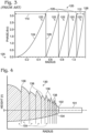
- Fig. 4 shows a cross-sectional view of a physical surface profile 130 of a diffractive structure fabricated in an upper optical surface 102 of a lens according to a preferred embodiment.
- a lower surface of the lens, 134 is a refractive surface.
- the radial width of each diffractive annular zone 104 decreases from the center of the lens to the edge of the lens to maintain equal areas of the diffractive zones.
- the step heights between each zone alternate between two values, starting with the larger step height 136 for the transition between the central zone and the first annular zone.
- a smaller step height 138 characterizes the transition between the first and second zones. This alternating step height pattern is repeated out to the edge of the lens.
- Fig. 5 shows a plot of the radial profile 140 of the optical phase change ⁇ (r) experienced by an incident light wave as it passes through an enhanced diffractive trifocal lens having the surface profile shown in Fig. 4 .
- Elements of radial profile 140 have a sawtooth shape 141 similar to sawtooth shape 122, in which each of the concentric zones is located at the same radius, but the step heights are not all substantially equal. Instead, a first set of peaks 142, having larger step heights 144, alternate with a second set of peaks 146 having smaller step heights 148.
- These features of the phase profile correspond to surface profile step heights 136 and 138, respectively.
- incident light power may be directed to the diffractive orders corresponding to distance, intermediate, and near vision.
- odd-numbered step heights are greater than even-numbered step heights, though in alternative embodiments, the reverse may be stipulated, while applying the same methodology for optimizing the design.
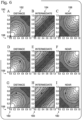
- Fig. 6 shows nine computer-generated topographic plots A - I of diffraction efficiencies for light power directed into the zeroth, +first, and +second diffraction orders. These diffraction orders represent distance vision 152, intermediate vision 154, and near vision 156, respectively for a diffractive multifocal lens having a generalized sawtooth-shaped phase profile consistent with both Figs. 3 and 5 , for which odd-numbered step heights and even-numbered step heights may take on different values.
- Faklis and Morris present diffraction efficiencies relevant to the phase profile of Fig. 3 by deriving an expression for the diffraction efficiency of the m th diffracted order, ⁇ m , by expanding the amplitude transmission function of the diffractive lens as a Fourier series, and extracting the Fourier coefficient, c m .
- ⁇ m sin ⁇ ⁇ p ⁇ m / ⁇ ⁇ p ⁇ m 2 .
- ⁇ m m ,p , ⁇ , A1 ,A2 sqrt 1 4 sinc ⁇ / 2 m ⁇ 2 A1 p ⁇ 2 + 2 ⁇ 1 m cos ⁇ A1 ⁇ A2 p ⁇ sinc ⁇ / 2 m ⁇ 2 A1 p ⁇ sinc ⁇ / 2 m ⁇ 2 A2p ⁇ + sinc ⁇ / 2 m ⁇ 2 A2p ⁇ 2 .
- a similar derivation may be performed for a lens design having three or more different step heights, yielding a different expression analogous to (5) for the specific example disclosed herein.
- horizontal axes 158 represent step heights of even numbered profile peaks, normalized to 2 ⁇
- vertical axes 160 represent step heights of odd numbered profile peaks, normalized to 2 ⁇ .
- the nine plots thus each provide a topographic "map" on which may be located points of interest marked with an "X" corresponding to examples of different diffractive lens designs, dictated by the choice of step heights A1 and A2.
- the maps thus indicate, by their relative shading at the point of interest, the amount of power directed into each focal region to yield different proportions of distance, intermediate, and near vision.
- step heights A1 and A2 may be chosen so as to enhance the diffraction efficiencies for all three foci equally, or they may be chosen so that the zeroth order diffraction efficiency is twice that of the +first and +second orders, which would yield better distance vision, at the expense of intermediate vision.
- the lightest shaded regions in each plot correspond to 100% diffraction efficiency, and the darkest shaded regions in each plot correspond to 0% diffraction efficiency.
- a similar set of plots may be generated for a lens design having three or more different step heights, A1, A2, and A3, according to a corresponding expression derived in a similar fashion as (5) above.
- Topographic plots A, B, and C in Fig. 6 illustrate a limiting case in which both the odd and even phase step heights 126, represented by variables A1 and A2, are set to zero i.e., this case represents the absence of a diffractive surface pattern, which is essentially a refractive lens. Plotting the point (0,0) on each of topographic plots A, B and C yields an "X" in the lower left corner of the topographic field.
- the X coincides with a bright spot, indicating that about 100% of the light is directed into the zeroth "diffraction order" (distance); in plots B and C, the X coincides with a dark region indicating that substantially no light is directed into the first and second diffraction orders (intermediate and near), consistent with the absence of a multifocal diffraction pattern in this example.
- Topographic plots D, E, and F in Fig. 6 illustrate the limiting case corresponding to a conventional bifocal diffractive lens, having the profile shown in Fig. 3 , in which both the odd and even step heights 126, represented by variables A1 and A2, are equal to 0.5 * 2 ⁇ . Plotting coordinates (0.5, 0.5) yields an "X" near the center of each plot.
- the X coincides with a grey region, indicating that substantially equal portions of light power are directed into the zeroth and second diffraction orders corresponding to distance and near vision.
- plot E the X coincides with a dark region, indicating that substantially 0% of the light power is directed to the first diffractive order, corresponding to intermediate vision.
- Topographic plots G, H and I in Fig. 6 illustrate a preferred embodiment of a multistep diffractive lens shown in Fig. 5 .
- odd step heights 136 are assigned a value 0.7 * 2 ⁇ and even step heights 138 are assigned a value 0.3 * 2 ⁇ , to yield optimal results.
- the reason for assigning these values can be appreciated by plotting the point (0.3, 0.7) on each of topographic plots G, H and I, which yields an "X" in the upper left quadrant of each plot.
- the X coincides with a light grey-shaded region, the greyscale value indicating that the light power is directed equally into each of the zeroth, first, and second diffractive orders, so that distance, intermediate, and near vision are all substantially equally enhanced.
- a more complex design example not embodying the present invention, for which a gradually decreasing phase profile is shown in Fig. 7 , provides a trifocal portion in the center of the lens, progressing to a bifocal lens at the edge of the lens.
- a pair of alternating step heights decrease monotonically from first prescribed values 166 and 168 at the center of the lens to second prescribed values 170 and 172 at the edge of the lens.
- step height values A1 and A2 may be chosen to be 0.3 ⁇ and 0.7 ⁇ at the center of the lens, and 0.1 ⁇ and 0.45 ⁇ at the edge of the lens respectively.
- a trifocal lens fabricated according to such a design would provide enhanced distance, intermediate, and near vision for a person having small pupils, and it would favor distance and intermediate vision for a person having large pupils, gradually reducing the near vision for large pupils. Visually, this would allow a person in bright lighting conditions to drive, see a computer monitor, and read, while under dark conditions when there is no need to read, it would allow the person to drive and see a dashboard more clearly.
Landscapes
- Health & Medical Sciences (AREA)
- Ophthalmology & Optometry (AREA)
- Physics & Mathematics (AREA)
- General Health & Medical Sciences (AREA)
- Optics & Photonics (AREA)
- General Physics & Mathematics (AREA)
- Engineering & Computer Science (AREA)
- Veterinary Medicine (AREA)
- Vascular Medicine (AREA)
- Life Sciences & Earth Sciences (AREA)
- Animal Behavior & Ethology (AREA)
- Biomedical Technology (AREA)
- Public Health (AREA)
- Heart & Thoracic Surgery (AREA)
- Transplantation (AREA)
- Oral & Maxillofacial Surgery (AREA)
- Cardiology (AREA)
- Mathematical Physics (AREA)
- Eyeglasses (AREA)
- Prostheses (AREA)
- Diffracting Gratings Or Hologram Optical Elements (AREA)
Description
- The present invention relates generally to the field of corrective multifocal intraocular and contact lenses.
- Bifocal and trifocal contact lenses are commonly used to treat presbyopia, a condition in which the eye exhibits a progressively diminished ability to focus on near objects. Human beings become presbyopic due to aging, and the effect typically becomes noticeable starting at about the age of 40 - 45 years, when they discover they need reading glasses. Presbyopic individuals who wear corrective lenses may then find that they need two separate prescriptions, preferably within the same bifocal lens, one for reading (near) and another for driving (distance). A trifocal lens further improves vision at intermediate distances, for example, when working at a computer. An intraocular lens (IOL) is an artificial replacement lens that may be used as an alternative to a contact lens or eyeglasses. An IOL is often implanted in place of the natural eye lens during cataract surgery. An intracorneal lens (ICL) is an artificial lens that is implanted into the cornea.
- Conventional corrective optics are typically refractive lenses, meaning that they bend and focus light rays reflected from an object to form a focused image of the object on the retina. The bending of the light rays is dictated by Snell's law which describes the degree of bending that occurs as light rays cross the boundary of two materials with distinct indices of refraction.
- Diffractive lenses have a repeating structure that may be formed in the surface of an optical element by a fabrication method such as, for example, cutting the surface using a lathe that may be equipped with a cutting head made of a hard mineral such as diamond or sapphire; direct write patterning using a high energy beam such as a laser beam or electron beam or a similar method of ablating the surface; etching the surface using a photolithographic patterning process; or molding the surface. The diffractive structure is typically a series of concentric annular zones, which requires each zone to become progressively narrower from the center to the edge of the lens. There may be, for example, 20 - 30 zones between the center and the edge of the lens. The surface profile within each zone is typically a smoothly varying function such as an arc, a parabola, or a line. At the outer periphery of each zone there is a discrete step in the vertical surface profile, the step height typically measuring about 0.5 - 3 microns. The resulting surface structure acts as a circularly symmetric diffraction grating that disperses light into multiple diffraction orders, each diffraction order having a consecutive number, zero, one, two, and so forth.
- "Diffraction efficiency" refers to the percentage of incident light power transmitted into each of the various diffractive orders comprising the diffraction pattern at the focal plane. If the zones have equal surface areas and are radially symmetric, they focus light of different diffraction orders onto the optical axis of the lens, each diffraction order having its own distinct foci. Thus, the diffractive lens acts as a multifocal lens having many discrete foci. For example, a diffractive bifocal lens simultaneously provides sharp retinal images of objects at two different distances, as well as two corresponding out-of-focus images. The human visual system has the ability to select from among the different retinal images, thereby enabling simultaneous multifocal vision using a single diffractive lens.
- Diffractive lenses may be used as contact lenses and IOLs for correcting presbyopia. In such an application, the lens comprises one refractive surface and one diffractive surface. In practice, the light energy passing through a diffractive lens is typically concentrated into one, two, or three diffractive orders, while contributing an insignificant amount of light energy to other diffractive orders. With respect to diffractive corrective lenses, for example, a high diffraction efficiency for the zeroth order connotes a greater improvement in visibility at far distances. The amount of optical energy directed into each diffraction order is dictated by the zonal step heights. A lens designer may choose, for the diffractive surface features of a bifocal lens, step heights so as to introduce, for example, a one-half wavelength phase change between adjacent zones, which directs approximately 40% of the incident light into the zeroth diffraction order corresponding to distance vision, and 40% into the positive first diffractive order, corresponding to near vision. The remaining 20% of the incident light in a conventional bifocal lens is directed to other diffraction orders that are not useful for vision. Existing designs for multifocal intraocular and contact lenses use either refractive optics, a combination refractive/diffractive design, or diffractive lenses that direct light into a single diffractive order. For example,
U.S. Patent No. 5,344,447 to Swanson , discloses a trifocal IOL design that enhances distance vision using a combination lens having a refractive surface and a diffractive surface. Each diffractive zone in this case corresponds to a binary step. This lens distributes light approximately equally between the positive first, zeroth, and negative first diffraction order. However, a drawback to this configuration is that excess light is directed into other higher diffractive orders, reducing visual quality. Furthermore, this configuration makes the power of the underlying carrier lens more difficult to predict because distance vision is dictated by a combination of the lens' refractive power with the diffractive power of the minus one diffractive order. None of the existing alternatives succeeds in directing enough light into a diffractive order that corresponds to an intermediate focal distance, and therefore trifocal contact lenses and IOLs fail to perform equally well throughout the full focal range. For example,U.S. Patent No. 7,441 ,894 to Zhang et al. discloses a trifocal intraocular lens having diffractive zones of varying areas capable of directing about 25 - 28% of incident light into the near and far foci, but only about 10% of the incident light is directed into the intermediate focus. - With reference to D1,
US 5122903 discloses an optical device and optical pickup device using the same. An optical element having a substrate and a composite grating pattern formed thereon is disclosed. The pattern is constituted with two different kinds of grating patterns superimposed on the substrate. When one of the two kinds of grating patterns is formed in a Fresnel lens pattern, a light focusing or collimating function (i.e. a lens function) is implemented. When the other pattern is formed in an equally separated linear grating pattern, the optical element develops the lens function and a function to diffract lights through the linear grating. When one of the two kinds of grating patterns is formed in a Fresnel lens pattern and the other pattern is implemented in an unequally separated linear grating pattern, a lens function to focus lights onto a point and a cylindrical lens function to focus lights in a linear contour are obtained. Consequently, when parallel lights are incident to the optical element, there occurs astigmatism. -
US 4 210 391 A discloses a multifocal Fresnel lens construction suitable for use in optical systems with multifocal requirements. It is designed as a multifocal zone plate to allow an annular ring construction that isn't width limited by diffraction aberrations. This is accomplished by modifying the phase separating annular rings of a zone plate, with curved or inclined optical facets of varying refractive indices, which can then function as Fresnel rings corresponding to the different focal powers desired. - A diffractive multifocal lens is disclosed, comprising an optical element having at least one diffractive surface, the surface profile of which comprises a plurality of concentric annular zones. The optical thickness of the radial surface profile changes monotonically within each zone. A distinct step in optical thickness occurs at the outer periphery of each zone, the size of which is referred to as a "step height." According to the invention, instead of being equal, the step heights for adjacent zones differ from one zone to another periodically so as to tailor diffraction order efficiencies of the optical element. There is particular interest in increasing at least the first order diffraction efficiency of the optical element to address intermediate distance vision for trifocal lenses.
- In one embodiment of a trifocal lens according to the present invention, the step heights alternate between two values. The even-numbered step heights may be lower than the odd-numbered step heights. In alternative embodiments, the even-numbered step heights may be higher than the odd-numbered step heights. In still another example, not embodying the present invention, the pattern of step heights gradually changes from the center to the edge of the lens. According to one such example, the center of the lens is trifocal, but it becomes progressively bifocal toward the edge of the lens. By modeling and plotting a topographical representation of the diffraction efficiencies resulting from such a surface profile, dimension parameters such as step height values may be selected so as to achieve directing a desired proportion of light power into designated diffraction orders, thereby optimizing the distance, intermediate, and near performance of the multifocal lens.
- It is to be understood that this summary is provided as a means for generally determining what follows in the drawings and detailed description, and is not intended to limit the scope of the invention. Objects, features and advantages of the invention will be readily understood upon consideration of the following detailed description taken in conjunction with the accompanying drawings.
-
-
Fig. 1 shows a commercially available prior art diffractive bifocal intraocular lens. -
Fig. 2 is a magnified view of the surface of a central zone of the prior art diffractive bifocal intraocular lens shown inFig. 1 , in which the center of the lens is located at the lower right hand corner of the image. -
Fig. 3 is a plot of the optical phase change introduced by a conventional prior art bifocal diffractive lens as a function of radius across five zones of the lens, showing generally equal step heights. -
Fig. 4 is a cross-sectional view of the radial surface profile for a diffractive structure according to a preferred embodiment of a novel trifocal diffractive lens, showing two alternating step heights. -
Fig. 5 is a plot of the optical phase change introduced by the diffractive structure shown inFig. 4 , as a function of radius, showing corresponding alternating step heights for five representative zones. -
Fig. 6 is a series of computer-generated two-dimensional topographic plots showing diffraction efficiencies that result from different choices of values for the alternating step heights in the optical phase profile ofFig. 5 . -
Fig. 7 is a plot of the optical phase change introduced by a graduated trifocal/bifocal diffractive structure not embodying the invention as a function of radius, showing corresponding alternating step heights. - The present invention will be readily understood by the following detailed description in conjunction with the accompanying drawings. To facilitate this description, like reference numerals designate like structural elements. In the following description many details are set forth to provide an understanding of the disclosed embodiments of the invention. However, upon reviewing this disclosure, it will become apparent to one skilled in the art that not all of the disclosed details may be required to practice the claimed invention and that alternative embodiments might be constructed without departing from the principles of the invention. Referring to
Fig. 1 , an existing diffractive bifocalintraocular lens 100 is shown. -
Lens 100 is commercially known as a ReSTOR® lens implant, and is available from Alcon Laboratories, Inc. of Fort Worth, Texas. The lens implant comprises a pair ofextensions 101 connected to a central optical element having at least oneoptical surface 102 in which a diffractive profile pattern is formed within radial zones.Fig. 2 shows a magnified view ofoptical surface 102, in which a generally radially symmetric surface profile pattern for a series of concentricannular zones 104 features, at the outer periphery of each zone, a discrete step106, havingstep height 108. The widths ofzones 104 generally decrease from the center toward the edge oflens 100 so that acentral zone width 110 may be significantly wider than anedge zone width 112. Zones of different widths preferably represent equal surface areas. In general, if thestep height 108 introduces a phase delay of 2π, a single power lens results i.e., the lens will have a single focus; if thestep height 108 introduces a phase delay not equal to a multiple of 2π, a bifocal lens results. -
Fig. 3 shows aradial profile 120 of the optical phase change experienced by an incident light wave as it passes through thediffractive lens 100.Radial profile 120 may be achieved by diffractive structures generally having sawtooth-shaped elements, or by varying the index of refraction of the lens material. The radial dependence of the phase change Φ(r) is given by

concentric regions 104 shown inFig. 2 is related to the radial phase change profile. The corresponding maximum height of the surface relief ofoptical surface 102 is given by
- Referring to
Fig. 3 , elements ofradial phase profile 120 have asawtooth shape 122, characterized by sharp peaks having aleading edge 124 that rises from afirst value 125 normalized to zero, gradually to apeak value 126, and a trailingedge 128 that falls abruptly from thepeak value 126 back to theinitial height 125. Thecentral ring width 110 corresponds to the radius of the first peak, and theedge ring width 112 corresponds to the distance between the fourth and fifth peaks in this example, in which peakvalues 126 are associated with substantially equal step heights. The radial phase profile ofFig. 3 is produced by a surface profile, the elements of which have a similar shape assawtooth 122, and which have an associated optical thickness profile that also has a similar shape assawtooth 122. Existing bifocalintraocular lenses 100 in this configuration typically have diffraction efficiencies of 40% into each of the zeroth and first diffractive orders (far and near distances, respectively), and substantially smaller diffraction efficiencies for higher diffractive orders. As a result, distance and near vision are enhanced, but intermediate vision is limited. -
Fig. 4 shows a cross-sectional view of aphysical surface profile 130 of a diffractive structure fabricated in an upperoptical surface 102 of a lens according to a preferred embodiment. A lower surface of the lens, 134, is a refractive surface. The radial width of each diffractiveannular zone 104 decreases from the center of the lens to the edge of the lens to maintain equal areas of the diffractive zones. The step heights between each zone alternate between two values, starting with thelarger step height 136 for the transition between the central zone and the first annular zone. Asmaller step height 138 characterizes the transition between the first and second zones. This alternating step height pattern is repeated out to the edge of the lens. -
Fig. 5 shows a plot of theradial profile 140 of the optical phase change Φ(r) experienced by an incident light wave as it passes through an enhanced diffractive trifocal lens having the surface profile shown inFig. 4 . Elements ofradial profile 140 have asawtooth shape 141 similar tosawtooth shape 122, in which each of the concentric zones is located at the same radius, but the step heights are not all substantially equal. Instead, a first set ofpeaks 142, having larger step heights 144, alternate with a second set ofpeaks 146 havingsmaller step heights 148. These features of the phase profile correspond to surfaceprofile step heights -
Fig. 6 shows nine computer-generated topographic plots A - I of diffraction efficiencies for light power directed into the zeroth, +first, and +second diffraction orders. These diffraction orders representdistance vision 152,intermediate vision 154, and nearvision 156, respectively for a diffractive multifocal lens having a generalized sawtooth-shaped phase profile consistent with bothFigs. 3 and5 , for which odd-numbered step heights and even-numbered step heights may take on different values. - An expression for calculating diffraction efficiencies for the phase profile of
Fig. 5 is derived by generalizing a scheme disclosed in an article by Faklis and Morris (Dean Faklis and G. Michael Morris, "Spectral Properties of Multiorder Diffractive Lenses," Applied Optics, Vol. 34, No. 14, May 10, 1995),sections 1 and 2. Faklis and Morris present diffraction efficiencies relevant to the phase profile ofFig. 3 by deriving an expression for the diffraction efficiency of the mth diffracted order, ηm, by expanding the amplitude transmission function of the diffractive lens as a Fourier series, and extracting the Fourier coefficient, cm. The diffraction efficiency, ηm, is then given by |cm|2. For a phase profile having substantially equal step heights, Faklis and Morris show that the diffraction efficiency may be expressed as
- By generalizing this derivation, it may be shown that the diffraction efficiency for the mth diffracted order for the phase profile of
Fig. 5 , having two dimension parameters {e.g., alternating step heights) A1 and A2, is given by:
- Referring to
Fig. 6 , a graph of ηm for m = 0 is shown in plots A, D, and G; a graph of ηm for m = +1 is shown in plots B, E, and H; and a graph of ηm for m = +2 is shown in plots C, F, and I. In each of the nine plots,horizontal axes 158 represent step heights of even numbered profile peaks, normalized to 2ττ, andvertical axes 160 represent step heights of odd numbered profile peaks, normalized to 2ττ. The nine plots thus each provide a topographic "map" on which may be located points of interest marked with an "X" corresponding to examples of different diffractive lens designs, dictated by the choice of step heights A1 and A2. The maps thus indicate, by their relative shading at the point of interest, the amount of power directed into each focal region to yield different proportions of distance, intermediate, and near vision. For example, step heights A1 and A2 may be chosen so as to enhance the diffraction efficiencies for all three foci equally, or they may be chosen so that the zeroth order diffraction efficiency is twice that of the +first and +second orders, which would yield better distance vision, at the expense of intermediate vision. The lightest shaded regions in each plot correspond to 100% diffraction efficiency, and the darkest shaded regions in each plot correspond to 0% diffraction efficiency. (A similar set of plots may be generated for a lens design having three or more different step heights, A1, A2, and A3, according to a corresponding expression derived in a similar fashion as (5) above.) - Topographic plots A, B, and C in
Fig. 6 illustrate a limiting case in which both the odd and evenphase step heights 126, represented by variables A1 and A2, are set to zero i.e., this case represents the absence of a diffractive surface pattern, which is essentially a refractive lens. Plotting the point (0,0) on each of topographic plots A, B and C yields an "X" in the lower left corner of the topographic field. In plot A, the X coincides with a bright spot, indicating that about 100% of the light is directed into the zeroth "diffraction order" (distance); in plots B and C, the X coincides with a dark region indicating that substantially no light is directed into the first and second diffraction orders (intermediate and near), consistent with the absence of a multifocal diffraction pattern in this example. - Topographic plots D, E, and F in
Fig. 6 illustrate the limiting case corresponding to a conventional bifocal diffractive lens, having the profile shown inFig. 3 , in which both the odd and even stepheights 126, represented by variables A1 and A2, are equal to 0.5 * 2ττ. Plotting coordinates (0.5, 0.5) yields an "X" near the center of each plot. In plots D and F, the X coincides with a grey region, indicating that substantially equal portions of light power are directed into the zeroth and second diffraction orders corresponding to distance and near vision. In plot E, the X coincides with a dark region, indicating that substantially 0% of the light power is directed to the first diffractive order, corresponding to intermediate vision. - Topographic plots G, H and I in
Fig. 6 illustrate a preferred embodiment of a multistep diffractive lens shown inFig. 5 . In this example,odd step heights 136 are assigned a value 0.7 * 2π and even stepheights 138 are assigned a value 0.3 * 2ττ, to yield optimal results. The reason for assigning these values can be appreciated by plotting the point (0.3, 0.7) on each of topographic plots G, H and I, which yields an "X" in the upper left quadrant of each plot. In each of the plots, the X coincides with a light grey-shaded region, the greyscale value indicating that the light power is directed equally into each of the zeroth, first, and second diffractive orders, so that distance, intermediate, and near vision are all substantially equally enhanced. - A more complex design example, not embodying the present invention, for which a gradually decreasing phase profile is shown in
Fig. 7 , provides a trifocal portion in the center of the lens, progressing to a bifocal lens at the edge of the lens. According to this example, a pair of alternating step heights decrease monotonically from firstprescribed values prescribed values - Although certain embodiments have been illustrated and described herein, it will be appreciated by those of ordinary skill in the art that a wide variety of alternative or equivalent embodiments or implementations calculated to achieve the same purposes may be substituted for the embodiments illustrated and described without departing from the scope of the present invention. Those with skill in the art will readily appreciate that embodiments in accordance with the present invention may be implemented in a very wide variety of ways. This application is intended to cover any adaptations or variations of the embodiments discussed herein.
- The terms and expressions which have been employed in the foregoing specification are used therein as terms of description and not of limitation, the scope of the invention is defined and limited only by the claims that follow.
Claims (8)
- A diffractive multifocal lens comprising an optical element having a first diffractive optical surface (102) having a radial surface profile (130) having a diffractive structure comprising a plurality of concentric annular zones (104) concentric with a central zone and assignable, from the outer edge of the central zone to the edge of the lens, as alternating odd and even numbered zones each having a projected surface area that is equal, wherein the optical thickness of the lens changes monotonically within each zone, a distinct step in optical thickness occurs at the outer periphery of each zone (104), at the junction between the zones (136, 138), the height of the steps alternating between two values (A1, A2), with this alternating step height pattern repeating periodically from the center to the edge of the lens so as to tailor the proportions of the diffraction order efficiencies of at least a zeroth, positive first, and positive second, diffractive order of the radial surface profile (130) of the optical element, wherein the lens has a radial phase profile, of the optical phase change introduced by the diffractive structure, and the radial phase profile within each of the concentric annular zones (104) consists of a sawtooth shape (141), characterized by a sharp peak (142, 146) having a leading edge (124) that rises from a first value normalized to zero, gradually to a peak value, and a trailing edge (128) that falls abruptly from the peak value back to the first value, wherein the first value is the same for each sawtooth shape (141).
- The lens of claim 1, wherein the step heights (136, 138) of the even numbered zones (104) are greater than the step heights of the odd numbered zones (104).
- The lens of claim 1, wherein the step heights (136, 138) of the even numbered zones (104) are less than the step heights of odd numbered zones (104).
- The lens of claim 1, wherein the step heights (136, 138) are chosen so that the diffraction efficiencies of at least the zeroth, positive first, and positive second orders are substantially equal.
- The lens of claim 1, wherein the projected surface area of each consecutive zone (104) is substantially constant.
- The lens of claim 1, wherein the radial surface profile height of each zone (104) forms an arc, or wherein the radial surface profile height of each zone (104) increases substantially linearly.
- The lens of claim 1, further comprising a second optical surface (134) that is a refractive optical surface separated from the first diffractive optical surface (130).
- The lens of claim 1, adapted to be worn as a contact lens, or adapted to be surgically implanted as an intraocular lens.
Priority Applications (1)
| Application Number | Priority Date | Filing Date | Title |
|---|---|---|---|
| EP20154708.0A EP3719544A1 (en) | 2009-02-12 | 2010-02-12 | Diffractive trifocal lens |
Applications Claiming Priority (2)
| Application Number | Priority Date | Filing Date | Title |
|---|---|---|---|
| US20740909P | 2009-02-12 | 2009-02-12 | |
| PCT/US2010/024165 WO2010093975A2 (en) | 2009-02-12 | 2010-02-12 | Diffractive trifocal lens |
Related Child Applications (2)
| Application Number | Title | Priority Date | Filing Date |
|---|---|---|---|
| EP20154708.0A Division-Into EP3719544A1 (en) | 2009-02-12 | 2010-02-12 | Diffractive trifocal lens |
| EP20154708.0A Division EP3719544A1 (en) | 2009-02-12 | 2010-02-12 | Diffractive trifocal lens |
Publications (4)
| Publication Number | Publication Date |
|---|---|
| EP2396683A2 EP2396683A2 (en) | 2011-12-21 |
| EP2396683A4 EP2396683A4 (en) | 2014-04-02 |
| EP2396683B1 EP2396683B1 (en) | 2020-04-08 |
| EP2396683B2 true EP2396683B2 (en) | 2024-11-13 |
Family
ID=42562305
Family Applications (2)
| Application Number | Title | Priority Date | Filing Date |
|---|---|---|---|
| EP20154708.0A Pending EP3719544A1 (en) | 2009-02-12 | 2010-02-12 | Diffractive trifocal lens |
| EP10741835.2A Active EP2396683B2 (en) | 2009-02-12 | 2010-02-12 | Diffractive trifocal lens |
Family Applications Before (1)
| Application Number | Title | Priority Date | Filing Date |
|---|---|---|---|
| EP20154708.0A Pending EP3719544A1 (en) | 2009-02-12 | 2010-02-12 | Diffractive trifocal lens |
Country Status (15)
| Country | Link |
|---|---|
| US (8) | US9320594B2 (en) |
| EP (2) | EP3719544A1 (en) |
| JP (2) | JP6042067B2 (en) |
| KR (1) | KR101727760B1 (en) |
| CN (1) | CN102395906B (en) |
| AU (1) | AU2010213535B2 (en) |
| BR (1) | BRPI1008369B1 (en) |
| CA (1) | CA2752164C (en) |
| ES (1) | ES2809181T5 (en) |
| IL (1) | IL214491A (en) |
| MX (1) | MX2011008529A (en) |
| NZ (1) | NZ594697A (en) |
| RU (1) | RU2516035C2 (en) |
| SG (2) | SG173630A1 (en) |
| WO (1) | WO2010093975A2 (en) |
Families Citing this family (60)
| Publication number | Priority date | Publication date | Assignee | Title |
|---|---|---|---|---|
| NZ594697A (en) | 2009-02-12 | 2014-02-28 | Univ Arizona State | Diffractive trifocal lens |
| US8531783B2 (en) * | 2010-02-09 | 2013-09-10 | Xceed Imaging Ltd. | Imaging method and system for imaging with extended depth of focus |
| US20120140166A1 (en) * | 2010-12-07 | 2012-06-07 | Abbott Medical Optics Inc. | Pupil dependent diffractive lens for near, intermediate, and far vision |
| CN102331654B (en) * | 2011-05-27 | 2013-06-26 | 苏州佳世达光电有限公司 | Projector, lens module used for projector and projector playing method |
| EP2890287B1 (en) | 2012-08-31 | 2020-10-14 | Amo Groningen B.V. | Multi-ring lens, systems and methods for extended depth of focus |
| ES2472121B1 (en) * | 2012-12-27 | 2015-04-13 | Consejo Superior De Investigaciones Científicas (Csic) | Refractive multifocal intraocular lens with optimized optical quality in a focus range and procedure to obtain it |
| KR102045534B1 (en) * | 2013-06-11 | 2019-11-15 | 엘지이노텍 주식회사 | Lens comprising doe patterns |
| CN104127263B (en) * | 2013-12-19 | 2016-03-02 | 爱博诺德(北京)医疗科技有限公司 | Multifocal intraocular lenses |
| WO2015159374A1 (en) * | 2014-04-15 | 2015-10-22 | 株式会社メニコン | Diffractive multifocal intraocular lens and method for manufacturing diffractive multifocal intraocular lens |
| US11000366B2 (en) | 2014-05-15 | 2021-05-11 | Alcon Inc. | Multifocal diffractive ophthalmic lens |
| US9335564B2 (en) * | 2014-05-15 | 2016-05-10 | Novartis Ag | Multifocal diffractive ophthalmic lens using suppressed diffractive order |
| US10285807B2 (en) * | 2015-04-14 | 2019-05-14 | Z Optics LLC | High definition and extended depth of field intraocular lens |
| EP3130314A1 (en) * | 2015-08-12 | 2017-02-15 | PhysIOL SA | Trifocal intraocular lens with extended range of vision and correction of longitudinal chromatic aberration |
| JP6698671B2 (en) * | 2015-10-01 | 2020-05-27 | 株式会社メニコン | Diffractive multifocal ophthalmic lens and method of manufacturing diffractive multifocal ophthalmic lens |
| CN108604023B (en) | 2016-02-01 | 2022-04-15 | E-视觉智能光学公司 | Prism-enhanced lens and method of using prism-enhanced lens |
| JP6913035B2 (en) * | 2016-02-09 | 2021-08-04 | 株式会社メニコン | Method for Manufacturing Diffractive Multifocal Lens for Eyes and Diffractive Multifocal Lens for Eyes |
| US10568734B2 (en) * | 2016-03-03 | 2020-02-25 | Novartis Ag | Adjusting the apodization pattern for diffractive IOLs |
| CN109477913B (en) * | 2016-05-05 | 2021-08-06 | 特拉麦迪思有限责任公司 | Intraocular lenses and related design and modeling methods |
| US10531950B2 (en) | 2016-11-16 | 2020-01-14 | Tatvum LLC | Intraocular lens having an extended depth of focus |
| CN113180887B (en) * | 2016-11-29 | 2024-04-26 | 爱尔康公司 | Intraocular lens with zone-by-zone step height control |
| US10426599B2 (en) | 2016-11-29 | 2019-10-01 | Novartis Ag | Multifocal lens having reduced chromatic aberrations |
| EP3582719B1 (en) * | 2017-02-14 | 2025-01-22 | Dave, Jagrat Natavar | Diffractive multifocal implantable lens device |
| EP3595584A1 (en) | 2017-03-17 | 2020-01-22 | AMO Groningen B.V. | Diffractive intraocular lenses for extended range of vision |
| DE102017112085B4 (en) | 2017-06-01 | 2026-05-07 | Carl Zeiss Meditec Ag | Artificial eye lens with integrated drug depot and method for manufacturing an artificial eye lens |
| DE102017112087B4 (en) | 2017-06-01 | 2025-10-16 | Carl Zeiss Meditec Ag | Artificial eye lens with laser-generated birefringent structure and method for producing an artificial eye lens |
| DE102017112086B4 (en) * | 2017-06-01 | 2026-01-29 | Carl Zeiss Meditec Ag | Artificial eye lens with diffractive grid structure and method for manufacturing an artificial eye lens |
| US11523897B2 (en) | 2017-06-23 | 2022-12-13 | Amo Groningen B.V. | Intraocular lenses for presbyopia treatment |
| EP4487816A3 (en) | 2017-06-28 | 2025-03-12 | Amo Groningen B.V. | Diffractive lenses and related intraocular lenses for presbyopia treatment |
| EP3639084B1 (en) | 2017-06-28 | 2025-01-01 | Amo Groningen B.V. | Extended range and related intraocular lenses for presbyopia treatment |
| US11327210B2 (en) * | 2017-06-30 | 2022-05-10 | Amo Groningen B.V. | Non-repeating echelettes and related intraocular lenses for presbyopia treatment |
| CN113331993B (en) | 2017-07-24 | 2024-08-23 | 爱尔康公司 | Ophthalmic lens with deformed sinusoidal phase-shifting structure |
| EP3731781B1 (en) | 2017-12-28 | 2022-02-23 | Medicontur Orvostechnikai KFT. | Diffractive artificial ophthalmic lens with optimised apodization and method for the production of such artificial ophthalmic lens |
| ES2913639T3 (en) | 2017-12-28 | 2022-06-03 | Medicontur Orvostechnikai Kft | Trifocal artificial ophthalmic lens and method for its production |
| US11624863B2 (en) * | 2018-01-16 | 2023-04-11 | Nikon Corporation | Diffractive optical element, optical system, optical apparatus and method for producing diffractive optical element |
| US11324588B2 (en) | 2018-04-09 | 2022-05-10 | Mediphacos Industrias Medicas S/A | Diffractive intraocular lens |
| US12204178B2 (en) | 2018-12-06 | 2025-01-21 | Amo Groningen B.V. | Diffractive lenses for presbyopia treatment |
| US11106056B2 (en) | 2019-03-28 | 2021-08-31 | Aizhong Zhang | Subzonal multifocal diffractive lens |
| CN114902120A (en) | 2019-12-30 | 2022-08-12 | 阿莫格罗宁根私营有限公司 | Achromatic lenses with zone-level mixing for vision treatment |
| CA3166308A1 (en) | 2019-12-30 | 2021-07-08 | Amo Groningen B.V. | Lenses having diffractive profiles with irregular width for vision treatment |
| WO2021136616A1 (en) | 2019-12-30 | 2021-07-08 | Amo Groningen B.V. | Achromatic lenses for vision treatment |
| DE102020201817A1 (en) * | 2020-02-13 | 2021-08-19 | Carl Zeiss Meditec Ag | Diffractive lens of the eye |
| CN115697249A (en) | 2020-06-01 | 2023-02-03 | 应用奈米医材科技股份有限公司 | Bifacial aspheric diffractive multifocal lenses and their manufacture and use |
| EP3939543A1 (en) | 2020-07-15 | 2022-01-19 | Hoya Corporation | Multifocal lens |
| EP4200665A1 (en) | 2020-08-21 | 2023-06-28 | VSY Biyoteknoloji Ve Ilac Sanayi Anonim Sirketi | A zonal diffractive ocular lens |
| WO2022039682A1 (en) | 2020-08-21 | 2022-02-24 | Vsy Biyoteknoloji Ve Ilac Sanayi A.S. | A zonal diffractive ocular lens |
| DE102020215362A1 (en) * | 2020-12-04 | 2022-06-09 | Carl Zeiss Meditec Ag | Ophthalmic lens and method of designing an ophthalmic lens |
| CN112946792B (en) * | 2021-02-07 | 2022-09-16 | 南京邮电大学 | A microlens for realizing bifocal focusing |
| WO2022177517A1 (en) | 2021-02-19 | 2022-08-25 | Vsy Biyoteknoloji Ve Ilac Sanayi A.S. | An adaptive multifocal diffractive ocular lens |
| WO2022249128A1 (en) | 2021-05-28 | 2022-12-01 | Alcon Inc. | Multifocal diffractive ophthalmic lenses with evenly spaced echelettes |
| CN113693779B (en) * | 2021-06-01 | 2023-03-14 | 天津世纪康泰生物医学工程有限公司 | Diffraction type multifocal intraocular lens with targeted light field distribution |
| WO2022263994A1 (en) | 2021-06-14 | 2022-12-22 | Alcon Inc. | Multifocal diffractive silicone hydrogel contact lenses |
| US12433740B2 (en) | 2021-07-09 | 2025-10-07 | Amo Groningen B.V. | Diffractive lenses for range of vision |
| CN113331994B (en) * | 2021-07-29 | 2021-12-07 | 微创视神医疗科技(上海)有限公司 | Intraocular lens |
| WO2023148170A1 (en) | 2022-02-01 | 2023-08-10 | Amo Groningen B.V. | Diffractive lenses with diffractive order shift |
| KR102723676B1 (en) * | 2022-04-21 | 2024-10-30 | 한양대학교 산학협력단 | Combined diffractive multi-focal intraocular lens |
| KR102792731B1 (en) * | 2022-07-18 | 2025-04-11 | 한양대학교 산학협력단 | Multi-focal lens with central axicon zone |
| WO2024069398A1 (en) * | 2022-09-27 | 2024-04-04 | Brien Holden Vision Institute Limited | Improved multifocal lens, lens system, and lens kit |
| CN120569663A (en) | 2023-02-28 | 2025-08-29 | 爱尔康公司 | Color mask for embedded contact lens |
| US20240399686A1 (en) | 2023-06-01 | 2024-12-05 | Alcon Inc. | Method for making embedded hydrogel contact lenses |
| US20250164823A1 (en) | 2023-11-20 | 2025-05-22 | Alcon Inc. | Embedded contact lens with a high refractive index insert therein |
Citations (2)
| Publication number | Priority date | Publication date | Assignee | Title |
|---|---|---|---|---|
| IE68759B1 (en) † | 1988-11-10 | 1996-07-10 | Allen L Cohen | Multifocals using phase shifting steps |
| EP2377493A1 (en) † | 2009-01-06 | 2011-10-19 | Menicon Co., Ltd. | Method for manufacturing aphakic intraocular lens |
Family Cites Families (44)
| Publication number | Priority date | Publication date | Assignee | Title |
|---|---|---|---|---|
| US4210391A (en) | 1977-09-14 | 1980-07-01 | Cohen Allen L | Multifocal zone plate |
| DE3377535D1 (en) | 1982-10-27 | 1988-09-01 | Pilkington Plc | Bifocal contact lens comprising a plurality of concentric zones |
| US4881804A (en) | 1987-11-12 | 1989-11-21 | Cohen Allen L | Multifocal phase plate with a pure refractive portion |
| US5054905A (en) | 1987-11-12 | 1991-10-08 | Cohen Allen L | Progressive intensity phase bifocal |
| CA1316728C (en) | 1988-04-01 | 1993-04-27 | Michael J. Simpson | Multi-focal diffractive ophthalmic lenses |
| ES2081811T3 (en) * | 1988-07-20 | 1996-03-16 | Allen L Dr Cohen | MULTIFOCAL DIFRACTIVE OPTICAL ELEMENT. |
| US4995714A (en) | 1988-08-26 | 1991-02-26 | Cohen Allen L | Multifocal optical device with novel phase zone plate and method for making |
| JP2899296B2 (en) * | 1988-11-10 | 1999-06-02 | アレン・エル・コーエン | Manufacturing method of multifocal phase plate |
| CN1021990C (en) * | 1988-11-10 | 1993-09-01 | 艾伦·L·科恩 | Multifocal lenses with phase shift steps |
| US5122903A (en) | 1989-03-15 | 1992-06-16 | Omron Corporation | Optical device and optical pickup device using the same |
| US5121980A (en) * | 1989-04-19 | 1992-06-16 | Cohen Allen L | Small aperture multifocal |
| JPH033502U (en) * | 1989-05-29 | 1991-01-14 | ||
| US5117309A (en) | 1989-06-15 | 1992-05-26 | Olympus Optical Co., Ltd. | Vari-focal lens system having graded refractive index lens |
| US4936666A (en) | 1989-08-08 | 1990-06-26 | Minnesota Mining And Manufacturing Company | Diffractive lens |
| GB9008580D0 (en) | 1990-04-17 | 1990-06-13 | Pilkington Diffractive Lenses | Manufacture of contact lenses |
| US5178636A (en) * | 1990-05-14 | 1993-01-12 | Iolab Corporation | Tuned fresnel lens for multifocal intraocular applications including small incision surgeries |
| US5117306A (en) * | 1990-07-17 | 1992-05-26 | Cohen Allen L | Diffraction bifocal with adjusted chromaticity |
| US5344447A (en) | 1992-11-12 | 1994-09-06 | Massachusetts Institute Of Technology | Diffractive trifocal intra-ocular lens design |
| GB9301614D0 (en) * | 1993-01-27 | 1993-03-17 | Pilkington Diffractive Lenses | Multifocal contact lens |
| US5699142A (en) * | 1994-09-01 | 1997-12-16 | Alcon Laboratories, Inc. | Diffractive multifocal ophthalmic lens |
| US6120148A (en) * | 1998-10-05 | 2000-09-19 | Bifocon Optics Gmbh | Diffractive lens |
| EP1279992A3 (en) | 2001-07-28 | 2004-12-01 | ESCHENBACH OPTIK GmbH + Co. | Lens to be built in into a spectacle frame |
| AU2003241740A1 (en) * | 2002-06-14 | 2003-12-31 | Menicon Co., Ltd. | Lens for eye |
| US6951391B2 (en) | 2003-06-16 | 2005-10-04 | Apollo Optical Systems Llc | Bifocal multiorder diffractive lenses for vision correction |
| US7025456B2 (en) | 2004-08-20 | 2006-04-11 | Apollo Optical Systems, Llc | Diffractive lenses for vision correction |
| US7156516B2 (en) | 2004-08-20 | 2007-01-02 | Apollo Optical Systems Llc | Diffractive lenses for vision correction |
| JP2006139246A (en) | 2004-10-15 | 2006-06-01 | Riverbell Kk | Multifocal lens and imaging system |
| US7188949B2 (en) | 2004-10-25 | 2007-03-13 | Advanced Medical Optics, Inc. | Ophthalmic lens with multiple phase plates |
| EP2527908B1 (en) | 2004-10-25 | 2019-03-20 | Johnson & Johnson Surgical Vision, Inc. | Ophthalmic lens with multiple phase plates |
| US20070171362A1 (en) | 2004-12-01 | 2007-07-26 | Simpson Michael J | Truncated diffractive intraocular lenses |
| US20060116764A1 (en) * | 2004-12-01 | 2006-06-01 | Simpson Michael J | Apodized aspheric diffractive lenses |
| US7073906B1 (en) | 2005-05-12 | 2006-07-11 | Valdemar Portney | Aspherical diffractive ophthalmic lens |
| EP3263069B1 (en) | 2005-05-20 | 2019-07-10 | Kowa Company, Ltd. | Intraocular lens |
| WO2006137355A1 (en) * | 2005-06-20 | 2006-12-28 | Riverbell Co., Ltd. | Multifocal lens and imaging system |
| RU2303961C1 (en) * | 2005-10-31 | 2007-08-10 | Закрытое акционерное общество "ИнтраОЛ" | Multi-focal intraocular lens and method of manufacture of that lens |
| US7481532B2 (en) | 2006-02-09 | 2009-01-27 | Alcon, Inc. | Pseudo-accommodative IOL having multiple diffractive patterns |
| US7441894B2 (en) | 2006-02-09 | 2008-10-28 | Alcon Manufacturing, Ltd. | Pseudo-accommodative IOL having diffractive zones with varying areas |
| US7572007B2 (en) | 2006-08-02 | 2009-08-11 | Alcon, Inc. | Apodized diffractive IOL with frustrated diffractive region |
| US20080058586A1 (en) * | 2006-09-05 | 2008-03-06 | Wilson-Cook Medical Inc. | Hood member for use with an endoscope |
| JP2009001169A (en) * | 2007-06-21 | 2009-01-08 | Denso Corp | Air passage switching device and vehicle air conditioner |
| US20090088840A1 (en) | 2007-10-02 | 2009-04-02 | Simpson Michael J | Zonal diffractive multifocal intraocular lenses |
| JP4551489B2 (en) | 2009-01-06 | 2010-09-29 | 株式会社メニコン | Manufacturing method of diffractive lens |
| NZ594697A (en) | 2009-02-12 | 2014-02-28 | Univ Arizona State | Diffractive trifocal lens |
| BE1019161A5 (en) | 2010-01-26 | 2012-04-03 | Physiol | INTRAOCULAR LENS. |
-
2010
- 2010-02-12 NZ NZ594697A patent/NZ594697A/en unknown
- 2010-02-12 SG SG2011057643A patent/SG173630A1/en unknown
- 2010-02-12 ES ES10741835T patent/ES2809181T5/en active Active
- 2010-02-12 RU RU2011137403/28A patent/RU2516035C2/en active
- 2010-02-12 US US13/201,440 patent/US9320594B2/en active Active
- 2010-02-12 WO PCT/US2010/024165 patent/WO2010093975A2/en not_active Ceased
- 2010-02-12 CN CN201080015833.5A patent/CN102395906B/en active Active
- 2010-02-12 KR KR1020117021206A patent/KR101727760B1/en active Active
- 2010-02-12 SG SG10201402266XA patent/SG10201402266XA/en unknown
- 2010-02-12 BR BRPI1008369-3A patent/BRPI1008369B1/en active IP Right Grant
- 2010-02-12 EP EP20154708.0A patent/EP3719544A1/en active Pending
- 2010-02-12 CA CA2752164A patent/CA2752164C/en active Active
- 2010-02-12 EP EP10741835.2A patent/EP2396683B2/en active Active
- 2010-02-12 MX MX2011008529A patent/MX2011008529A/en active IP Right Grant
- 2010-02-12 AU AU2010213535A patent/AU2010213535B2/en not_active Withdrawn - After Issue
- 2010-02-12 JP JP2011550292A patent/JP6042067B2/en active Active
-
2011
- 2011-08-07 IL IL214491A patent/IL214491A/en active IP Right Grant
-
2016
- 2016-04-22 US US15/136,770 patent/US10209533B2/en active Active
- 2016-07-07 JP JP2016135250A patent/JP2016189026A/en not_active Withdrawn
-
2019
- 2019-01-17 US US16/250,866 patent/US10725320B2/en active Active
-
2020
- 2020-07-20 US US16/933,106 patent/US11199725B2/en active Active
-
2021
- 2021-12-09 US US17/547,115 patent/US11693260B2/en active Active
-
2023
- 2023-06-22 US US18/213,147 patent/US12164181B2/en active Active
-
2024
- 2024-11-20 US US18/954,376 patent/US12339526B2/en active Active
-
2025
- 2025-05-30 US US19/224,451 patent/US20260010016A1/en active Pending
Patent Citations (2)
| Publication number | Priority date | Publication date | Assignee | Title |
|---|---|---|---|---|
| IE68759B1 (en) † | 1988-11-10 | 1996-07-10 | Allen L Cohen | Multifocals using phase shifting steps |
| EP2377493A1 (en) † | 2009-01-06 | 2011-10-19 | Menicon Co., Ltd. | Method for manufacturing aphakic intraocular lens |
Also Published As
Similar Documents
| Publication | Publication Date | Title |
|---|---|---|
| US12339526B2 (en) | Diffractive trifocal lens | |
| US4210391A (en) | Multifocal zone plate | |
| US5748282A (en) | Multifocal contact lens | |
| JPH08507158A (en) | Multifocal contact lens | |
| EP3415980B1 (en) | Diffractive multifocal lens for eye and method for manufacturing diffractive multifocal lens for eye | |
| JPH0219822A (en) | Multi-contour diffraction lens | |
| US20240094558A1 (en) | Ophthalmic lens and method for designing an ophthalmic lens | |
| EP4200664A1 (en) | A zonal diffractive ocular lens | |
| EP4200665A1 (en) | A zonal diffractive ocular lens |
Legal Events
| Date | Code | Title | Description |
|---|---|---|---|
| PUAI | Public reference made under article 153(3) epc to a published international application that has entered the european phase |
Free format text: ORIGINAL CODE: 0009012 |
|
| 17P | Request for examination filed |
Effective date: 20110817 |
|
| AK | Designated contracting states |
Kind code of ref document: A2 Designated state(s): AT BE BG CH CY CZ DE DK EE ES FI FR GB GR HR HU IE IS IT LI LT LU LV MC MK MT NL NO PL PT RO SE SI SK SM TR |
|
| DAX | Request for extension of the european patent (deleted) | ||
| A4 | Supplementary search report drawn up and despatched |
Effective date: 20140304 |
|
| RIC1 | Information provided on ipc code assigned before grant |
Ipc: G02C 7/04 20060101ALI20140226BHEP Ipc: G02B 5/18 20060101ALI20140226BHEP Ipc: A61F 2/16 20060101ALI20140226BHEP Ipc: A61F 2/12 20060101ALI20140226BHEP Ipc: G02C 7/06 20060101ALI20140226BHEP Ipc: G02B 3/10 20060101AFI20140226BHEP |
|
| TPAC | Observations filed by third parties |
Free format text: ORIGINAL CODE: EPIDOSNTIPA |
|
| TPAC | Observations filed by third parties |
Free format text: ORIGINAL CODE: EPIDOSNTIPA |
|
| STAA | Information on the status of an ep patent application or granted ep patent |
Free format text: STATUS: EXAMINATION IS IN PROGRESS |
|
| 17Q | First examination report despatched |
Effective date: 20161110 |
|
| TPAC | Observations filed by third parties |
Free format text: ORIGINAL CODE: EPIDOSNTIPA |
|
| TPAC | Observations filed by third parties |
Free format text: ORIGINAL CODE: EPIDOSNTIPA |
|
| TPAC | Observations filed by third parties |
Free format text: ORIGINAL CODE: EPIDOSNTIPA |
|
| GRAP | Despatch of communication of intention to grant a patent |
Free format text: ORIGINAL CODE: EPIDOSNIGR1 |
|
| STAA | Information on the status of an ep patent application or granted ep patent |
Free format text: STATUS: GRANT OF PATENT IS INTENDED |
|
| INTG | Intention to grant announced |
Effective date: 20191107 |
|
| GRAS | Grant fee paid |
Free format text: ORIGINAL CODE: EPIDOSNIGR3 |
|
| GRAJ | Information related to disapproval of communication of intention to grant by the applicant or resumption of examination proceedings by the epo deleted |
Free format text: ORIGINAL CODE: EPIDOSDIGR1 |
|
| GRAL | Information related to payment of fee for publishing/printing deleted |
Free format text: ORIGINAL CODE: EPIDOSDIGR3 |
|
| STAA | Information on the status of an ep patent application or granted ep patent |
Free format text: STATUS: EXAMINATION IS IN PROGRESS |
|
| GRAR | Information related to intention to grant a patent recorded |
Free format text: ORIGINAL CODE: EPIDOSNIGR71 |
|
| STAA | Information on the status of an ep patent application or granted ep patent |
Free format text: STATUS: GRANT OF PATENT IS INTENDED |
|
| INTC | Intention to grant announced (deleted) | ||
| GRAA | (expected) grant |
Free format text: ORIGINAL CODE: 0009210 |
|
| STAA | Information on the status of an ep patent application or granted ep patent |
Free format text: STATUS: THE PATENT HAS BEEN GRANTED |
|
| INTG | Intention to grant announced |
Effective date: 20200211 |
|
| AK | Designated contracting states |
Kind code of ref document: B1 Designated state(s): AT BE BG CH CY CZ DE DK EE ES FI FR GB GR HR HU IE IS IT LI LT LU LV MC MK MT NL NO PL PT RO SE SI SK SM TR |
|
| REG | Reference to a national code |
Ref country code: GB Ref legal event code: FG4D |
|
| REG | Reference to a national code |
Ref country code: AT Ref legal event code: REF Ref document number: 1255154 Country of ref document: AT Kind code of ref document: T Effective date: 20200415 Ref country code: CH Ref legal event code: EP |
|
| REG | Reference to a national code |
Ref country code: IE Ref legal event code: FG4D |
|
| REG | Reference to a national code |
Ref country code: DE Ref legal event code: R096 Ref document number: 602010063823 Country of ref document: DE |
|
| REG | Reference to a national code |
Ref country code: NL Ref legal event code: FP |
|
| REG | Reference to a national code |
Ref country code: LT Ref legal event code: MG4D |
|
| PG25 | Lapsed in a contracting state [announced via postgrant information from national office to epo] |
Ref country code: LT Free format text: LAPSE BECAUSE OF FAILURE TO SUBMIT A TRANSLATION OF THE DESCRIPTION OR TO PAY THE FEE WITHIN THE PRESCRIBED TIME-LIMIT Effective date: 20200408 Ref country code: SE Free format text: LAPSE BECAUSE OF FAILURE TO SUBMIT A TRANSLATION OF THE DESCRIPTION OR TO PAY THE FEE WITHIN THE PRESCRIBED TIME-LIMIT Effective date: 20200408 Ref country code: FI Free format text: LAPSE BECAUSE OF FAILURE TO SUBMIT A TRANSLATION OF THE DESCRIPTION OR TO PAY THE FEE WITHIN THE PRESCRIBED TIME-LIMIT Effective date: 20200408 Ref country code: GR Free format text: LAPSE BECAUSE OF FAILURE TO SUBMIT A TRANSLATION OF THE DESCRIPTION OR TO PAY THE FEE WITHIN THE PRESCRIBED TIME-LIMIT Effective date: 20200709 Ref country code: NO Free format text: LAPSE BECAUSE OF FAILURE TO SUBMIT A TRANSLATION OF THE DESCRIPTION OR TO PAY THE FEE WITHIN THE PRESCRIBED TIME-LIMIT Effective date: 20200708 Ref country code: IS Free format text: LAPSE BECAUSE OF FAILURE TO SUBMIT A TRANSLATION OF THE DESCRIPTION OR TO PAY THE FEE WITHIN THE PRESCRIBED TIME-LIMIT Effective date: 20200808 Ref country code: PT Free format text: LAPSE BECAUSE OF FAILURE TO SUBMIT A TRANSLATION OF THE DESCRIPTION OR TO PAY THE FEE WITHIN THE PRESCRIBED TIME-LIMIT Effective date: 20200817 |
|
| REG | Reference to a national code |
Ref country code: AT Ref legal event code: MK05 Ref document number: 1255154 Country of ref document: AT Kind code of ref document: T Effective date: 20200408 |
|
| PG25 | Lapsed in a contracting state [announced via postgrant information from national office to epo] |
Ref country code: HR Free format text: LAPSE BECAUSE OF FAILURE TO SUBMIT A TRANSLATION OF THE DESCRIPTION OR TO PAY THE FEE WITHIN THE PRESCRIBED TIME-LIMIT Effective date: 20200408 Ref country code: LV Free format text: LAPSE BECAUSE OF FAILURE TO SUBMIT A TRANSLATION OF THE DESCRIPTION OR TO PAY THE FEE WITHIN THE PRESCRIBED TIME-LIMIT Effective date: 20200408 Ref country code: BG Free format text: LAPSE BECAUSE OF FAILURE TO SUBMIT A TRANSLATION OF THE DESCRIPTION OR TO PAY THE FEE WITHIN THE PRESCRIBED TIME-LIMIT Effective date: 20200708 |
|
| REG | Reference to a national code |
Ref country code: DE Ref legal event code: R026 Ref document number: 602010063823 Country of ref document: DE |
|
| PLBI | Opposition filed |
Free format text: ORIGINAL CODE: 0009260 |
|
| PLAX | Notice of opposition and request to file observation + time limit sent |
Free format text: ORIGINAL CODE: EPIDOSNOBS2 |
|
| PG25 | Lapsed in a contracting state [announced via postgrant information from national office to epo] |
Ref country code: CZ Free format text: LAPSE BECAUSE OF FAILURE TO SUBMIT A TRANSLATION OF THE DESCRIPTION OR TO PAY THE FEE WITHIN THE PRESCRIBED TIME-LIMIT Effective date: 20200408 Ref country code: RO Free format text: LAPSE BECAUSE OF FAILURE TO SUBMIT A TRANSLATION OF THE DESCRIPTION OR TO PAY THE FEE WITHIN THE PRESCRIBED TIME-LIMIT Effective date: 20200408 Ref country code: DK Free format text: LAPSE BECAUSE OF FAILURE TO SUBMIT A TRANSLATION OF THE DESCRIPTION OR TO PAY THE FEE WITHIN THE PRESCRIBED TIME-LIMIT Effective date: 20200408 Ref country code: SM Free format text: LAPSE BECAUSE OF FAILURE TO SUBMIT A TRANSLATION OF THE DESCRIPTION OR TO PAY THE FEE WITHIN THE PRESCRIBED TIME-LIMIT Effective date: 20200408 Ref country code: EE Free format text: LAPSE BECAUSE OF FAILURE TO SUBMIT A TRANSLATION OF THE DESCRIPTION OR TO PAY THE FEE WITHIN THE PRESCRIBED TIME-LIMIT Effective date: 20200408 Ref country code: AT Free format text: LAPSE BECAUSE OF FAILURE TO SUBMIT A TRANSLATION OF THE DESCRIPTION OR TO PAY THE FEE WITHIN THE PRESCRIBED TIME-LIMIT Effective date: 20200408 |
|
| 26 | Opposition filed |
Opponent name: PHYSIOL Effective date: 20210106 Opponent name: WRAYS SOLUTIONS PTY LTD Effective date: 20210105 |
|
| PG25 | Lapsed in a contracting state [announced via postgrant information from national office to epo] |
Ref country code: SK Free format text: LAPSE BECAUSE OF FAILURE TO SUBMIT A TRANSLATION OF THE DESCRIPTION OR TO PAY THE FEE WITHIN THE PRESCRIBED TIME-LIMIT Effective date: 20200408 Ref country code: PL Free format text: LAPSE BECAUSE OF FAILURE TO SUBMIT A TRANSLATION OF THE DESCRIPTION OR TO PAY THE FEE WITHIN THE PRESCRIBED TIME-LIMIT Effective date: 20200408 |
|
| REG | Reference to a national code |
Ref country code: ES Ref legal event code: FG2A Ref document number: 2809181 Country of ref document: ES Kind code of ref document: T3 Effective date: 20210303 |
|
| PG25 | Lapsed in a contracting state [announced via postgrant information from national office to epo] |
Ref country code: SI Free format text: LAPSE BECAUSE OF FAILURE TO SUBMIT A TRANSLATION OF THE DESCRIPTION OR TO PAY THE FEE WITHIN THE PRESCRIBED TIME-LIMIT Effective date: 20200408 |
|
| PLBB | Reply of patent proprietor to notice(s) of opposition received |
Free format text: ORIGINAL CODE: EPIDOSNOBS3 |
|
| PG25 | Lapsed in a contracting state [announced via postgrant information from national office to epo] |
Ref country code: MC Free format text: LAPSE BECAUSE OF FAILURE TO SUBMIT A TRANSLATION OF THE DESCRIPTION OR TO PAY THE FEE WITHIN THE PRESCRIBED TIME-LIMIT Effective date: 20200408 |
|
| REG | Reference to a national code |
Ref country code: BE Ref legal event code: MM Effective date: 20210228 |
|
| PG25 | Lapsed in a contracting state [announced via postgrant information from national office to epo] |
Ref country code: LU Free format text: LAPSE BECAUSE OF NON-PAYMENT OF DUE FEES Effective date: 20210212 |
|
| PG25 | Lapsed in a contracting state [announced via postgrant information from national office to epo] |
Ref country code: BE Free format text: LAPSE BECAUSE OF NON-PAYMENT OF DUE FEES Effective date: 20210228 |
|
| APAH | Appeal reference modified |
Free format text: ORIGINAL CODE: EPIDOSCREFNO |
|
| APBM | Appeal reference recorded |
Free format text: ORIGINAL CODE: EPIDOSNREFNO |
|
| APBP | Date of receipt of notice of appeal recorded |
Free format text: ORIGINAL CODE: EPIDOSNNOA2O |
|
| APBQ | Date of receipt of statement of grounds of appeal recorded |
Free format text: ORIGINAL CODE: EPIDOSNNOA3O |
|
| PG25 | Lapsed in a contracting state [announced via postgrant information from national office to epo] |
Ref country code: HU Free format text: LAPSE BECAUSE OF FAILURE TO SUBMIT A TRANSLATION OF THE DESCRIPTION OR TO PAY THE FEE WITHIN THE PRESCRIBED TIME-LIMIT; INVALID AB INITIO Effective date: 20100212 Ref country code: CY Free format text: LAPSE BECAUSE OF FAILURE TO SUBMIT A TRANSLATION OF THE DESCRIPTION OR TO PAY THE FEE WITHIN THE PRESCRIBED TIME-LIMIT Effective date: 20200408 |
|
| P01 | Opt-out of the competence of the unified patent court (upc) registered |
Effective date: 20230613 |
|
| PG25 | Lapsed in a contracting state [announced via postgrant information from national office to epo] |
Ref country code: MK Free format text: LAPSE BECAUSE OF FAILURE TO SUBMIT A TRANSLATION OF THE DESCRIPTION OR TO PAY THE FEE WITHIN THE PRESCRIBED TIME-LIMIT Effective date: 20200408 |
|
| APBU | Appeal procedure closed |
Free format text: ORIGINAL CODE: EPIDOSNNOA9O |
|
| PG25 | Lapsed in a contracting state [announced via postgrant information from national office to epo] |
Ref country code: MT Free format text: LAPSE BECAUSE OF FAILURE TO SUBMIT A TRANSLATION OF THE DESCRIPTION OR TO PAY THE FEE WITHIN THE PRESCRIBED TIME-LIMIT Effective date: 20200408 |
|
| PUAH | Patent maintained in amended form |
Free format text: ORIGINAL CODE: 0009272 |
|
| STAA | Information on the status of an ep patent application or granted ep patent |
Free format text: STATUS: PATENT MAINTAINED AS AMENDED |
|
| 27A | Patent maintained in amended form |
Effective date: 20241113 |
|
| AK | Designated contracting states |
Kind code of ref document: B2 Designated state(s): AT BE BG CH CY CZ DE DK EE ES FI FR GB GR HR HU IE IS IT LI LT LU LV MC MK MT NL NO PL PT RO SE SI SK SM TR |
|
| REG | Reference to a national code |
Ref country code: DE Ref legal event code: R102 Ref document number: 602010063823 Country of ref document: DE |
|
| REG | Reference to a national code |
Ref country code: NL Ref legal event code: FP |
|
| REG | Reference to a national code |
Ref country code: ES Ref legal event code: DC2A Ref document number: 2809181 Country of ref document: ES Kind code of ref document: T5 Effective date: 20250226 |
|
| REG | Reference to a national code |
Ref country code: CH Ref legal event code: U11 Free format text: ST27 STATUS EVENT CODE: U-0-0-U10-U11 (AS PROVIDED BY THE NATIONAL OFFICE) Effective date: 20260301 |
|
| PGFP | Annual fee paid to national office [announced via postgrant information from national office to epo] |
Ref country code: NL Payment date: 20260226 Year of fee payment: 17 |
|
| PGFP | Annual fee paid to national office [announced via postgrant information from national office to epo] |
Ref country code: GB Payment date: 20260227 Year of fee payment: 17 |
|
| PGFP | Annual fee paid to national office [announced via postgrant information from national office to epo] |
Ref country code: ES Payment date: 20260302 Year of fee payment: 17 |
|
| PGFP | Annual fee paid to national office [announced via postgrant information from national office to epo] |
Ref country code: DE Payment date: 20260227 Year of fee payment: 17 Ref country code: IE Payment date: 20260227 Year of fee payment: 17 |
|
| PGFP | Annual fee paid to national office [announced via postgrant information from national office to epo] |
Ref country code: IT Payment date: 20260219 Year of fee payment: 17 |
|
| PGFP | Annual fee paid to national office [announced via postgrant information from national office to epo] |
Ref country code: FR Payment date: 20260225 Year of fee payment: 17 |
|
| PGFP | Annual fee paid to national office [announced via postgrant information from national office to epo] |
Ref country code: TR Payment date: 20260206 Year of fee payment: 17 |
|
| PGFP | Annual fee paid to national office [announced via postgrant information from national office to epo] |
Ref country code: CH Payment date: 20260301 Year of fee payment: 17 |