CN109477913B - Intraocular lenses and related design and modeling methods - Google Patents
Intraocular lenses and related design and modeling methods Download PDFInfo
- Publication number
- CN109477913B CN109477913B CN201780027799.5A CN201780027799A CN109477913B CN 109477913 B CN109477913 B CN 109477913B CN 201780027799 A CN201780027799 A CN 201780027799A CN 109477913 B CN109477913 B CN 109477913B
- Authority
- CN
- China
- Prior art keywords
- optical
- intraocular lens
- multifocal intraocular
- diffraction
- diffractive
- Prior art date
- Legal status (The legal status is an assumption and is not a legal conclusion. Google has not performed a legal analysis and makes no representation as to the accuracy of the status listed.)
- Active
Links
- 238000013461 design Methods 0.000 title claims abstract description 67
- 238000000034 method Methods 0.000 title claims abstract description 49
- 230000003287 optical effect Effects 0.000 claims abstract description 97
- 230000006870 function Effects 0.000 claims description 39
- 210000001747 pupil Anatomy 0.000 claims description 32
- 238000009826 distribution Methods 0.000 claims description 22
- 238000003384 imaging method Methods 0.000 claims description 18
- 238000012546 transfer Methods 0.000 claims description 17
- 238000004088 simulation Methods 0.000 claims description 16
- 230000007480 spreading Effects 0.000 claims description 2
- 230000008859 change Effects 0.000 abstract description 5
- 230000001902 propagating effect Effects 0.000 abstract description 3
- 239000000463 material Substances 0.000 description 26
- 230000001427 coherent effect Effects 0.000 description 5
- 208000001491 myopia Diseases 0.000 description 5
- 239000013307 optical fiber Substances 0.000 description 4
- 230000004044 response Effects 0.000 description 4
- 210000001525 retina Anatomy 0.000 description 4
- 239000000654 additive Substances 0.000 description 3
- 230000000996 additive effect Effects 0.000 description 3
- 230000008901 benefit Effects 0.000 description 3
- 238000004364 calculation method Methods 0.000 description 3
- 238000009795 derivation Methods 0.000 description 3
- 230000003247 decreasing effect Effects 0.000 description 2
- 238000011156 evaluation Methods 0.000 description 2
- 208000002177 Cataract Diseases 0.000 description 1
- 230000009471 action Effects 0.000 description 1
- 230000015556 catabolic process Effects 0.000 description 1
- 238000006731 degradation reaction Methods 0.000 description 1
- 238000010586 diagram Methods 0.000 description 1
- 230000009977 dual effect Effects 0.000 description 1
- 238000002955 isolation Methods 0.000 description 1
- 238000005259 measurement Methods 0.000 description 1
- 238000012986 modification Methods 0.000 description 1
- 230000004048 modification Effects 0.000 description 1
- 238000005457 optimization Methods 0.000 description 1
- 201000010041 presbyopia Diseases 0.000 description 1
- 230000005855 radiation Effects 0.000 description 1
- 238000001228 spectrum Methods 0.000 description 1
- 238000001356 surgical procedure Methods 0.000 description 1
Images


Classifications
-
- A—HUMAN NECESSITIES
- A61—MEDICAL OR VETERINARY SCIENCE; HYGIENE
- A61F—FILTERS IMPLANTABLE INTO BLOOD VESSELS; PROSTHESES; DEVICES PROVIDING PATENCY TO, OR PREVENTING COLLAPSING OF, TUBULAR STRUCTURES OF THE BODY, e.g. STENTS; ORTHOPAEDIC, NURSING OR CONTRACEPTIVE DEVICES; FOMENTATION; TREATMENT OR PROTECTION OF EYES OR EARS; BANDAGES, DRESSINGS OR ABSORBENT PADS; FIRST-AID KITS
- A61F2/00—Filters implantable into blood vessels; Prostheses, i.e. artificial substitutes or replacements for parts of the body; Appliances for connecting them with the body; Devices providing patency to, or preventing collapsing of, tubular structures of the body, e.g. stents
- A61F2/02—Prostheses implantable into the body
- A61F2/14—Eye parts, e.g. lenses, corneal implants; Implanting instruments specially adapted therefor; Artificial eyes
- A61F2/16—Intraocular lenses
- A61F2/1613—Intraocular lenses having special lens configurations, e.g. multipart lenses; having particular optical properties, e.g. pseudo-accommodative lenses, lenses having aberration corrections, diffractive lenses, lenses for variably absorbing electromagnetic radiation, lenses having variable focus
- A61F2/1654—Diffractive lenses
- A61F2/1656—Fresnel lenses, prisms or plates
-
- G—PHYSICS
- G02—OPTICS
- G02B—OPTICAL ELEMENTS, SYSTEMS OR APPARATUS
- G02B3/00—Simple or compound lenses
- G02B3/10—Bifocal lenses; Multifocal lenses
-
- A—HUMAN NECESSITIES
- A61—MEDICAL OR VETERINARY SCIENCE; HYGIENE
- A61F—FILTERS IMPLANTABLE INTO BLOOD VESSELS; PROSTHESES; DEVICES PROVIDING PATENCY TO, OR PREVENTING COLLAPSING OF, TUBULAR STRUCTURES OF THE BODY, e.g. STENTS; ORTHOPAEDIC, NURSING OR CONTRACEPTIVE DEVICES; FOMENTATION; TREATMENT OR PROTECTION OF EYES OR EARS; BANDAGES, DRESSINGS OR ABSORBENT PADS; FIRST-AID KITS
- A61F2/00—Filters implantable into blood vessels; Prostheses, i.e. artificial substitutes or replacements for parts of the body; Appliances for connecting them with the body; Devices providing patency to, or preventing collapsing of, tubular structures of the body, e.g. stents
- A61F2/02—Prostheses implantable into the body
- A61F2/14—Eye parts, e.g. lenses, corneal implants; Implanting instruments specially adapted therefor; Artificial eyes
- A61F2/16—Intraocular lenses
- A61F2/1613—Intraocular lenses having special lens configurations, e.g. multipart lenses; having particular optical properties, e.g. pseudo-accommodative lenses, lenses having aberration corrections, diffractive lenses, lenses for variably absorbing electromagnetic radiation, lenses having variable focus
- A61F2/1616—Pseudo-accommodative, e.g. multifocal or enabling monovision
- A61F2/1618—Multifocal lenses
-
- A—HUMAN NECESSITIES
- A61—MEDICAL OR VETERINARY SCIENCE; HYGIENE
- A61F—FILTERS IMPLANTABLE INTO BLOOD VESSELS; PROSTHESES; DEVICES PROVIDING PATENCY TO, OR PREVENTING COLLAPSING OF, TUBULAR STRUCTURES OF THE BODY, e.g. STENTS; ORTHOPAEDIC, NURSING OR CONTRACEPTIVE DEVICES; FOMENTATION; TREATMENT OR PROTECTION OF EYES OR EARS; BANDAGES, DRESSINGS OR ABSORBENT PADS; FIRST-AID KITS
- A61F2/00—Filters implantable into blood vessels; Prostheses, i.e. artificial substitutes or replacements for parts of the body; Appliances for connecting them with the body; Devices providing patency to, or preventing collapsing of, tubular structures of the body, e.g. stents
- A61F2/02—Prostheses implantable into the body
- A61F2/14—Eye parts, e.g. lenses, corneal implants; Implanting instruments specially adapted therefor; Artificial eyes
- A61F2/16—Intraocular lenses
- A61F2/1613—Intraocular lenses having special lens configurations, e.g. multipart lenses; having particular optical properties, e.g. pseudo-accommodative lenses, lenses having aberration corrections, diffractive lenses, lenses for variably absorbing electromagnetic radiation, lenses having variable focus
- A61F2/1654—Diffractive lenses
-
- G—PHYSICS
- G02—OPTICS
- G02C—SPECTACLES; SUNGLASSES OR GOGGLES INSOFAR AS THEY HAVE THE SAME FEATURES AS SPECTACLES; CONTACT LENSES
- G02C7/00—Optical parts
- G02C7/02—Lenses; Lens systems ; Methods of designing lenses
- G02C7/04—Contact lenses for the eyes
- G02C7/041—Contact lenses for the eyes bifocal; multifocal
- G02C7/042—Simultaneous type
-
- A—HUMAN NECESSITIES
- A61—MEDICAL OR VETERINARY SCIENCE; HYGIENE
- A61F—FILTERS IMPLANTABLE INTO BLOOD VESSELS; PROSTHESES; DEVICES PROVIDING PATENCY TO, OR PREVENTING COLLAPSING OF, TUBULAR STRUCTURES OF THE BODY, e.g. STENTS; ORTHOPAEDIC, NURSING OR CONTRACEPTIVE DEVICES; FOMENTATION; TREATMENT OR PROTECTION OF EYES OR EARS; BANDAGES, DRESSINGS OR ABSORBENT PADS; FIRST-AID KITS
- A61F2240/00—Manufacturing or designing of prostheses classified in groups A61F2/00 - A61F2/26 or A61F2/82 or A61F9/00 or A61F11/00 or subgroups thereof
- A61F2240/001—Designing or manufacturing processes
-
- G—PHYSICS
- G02—OPTICS
- G02B—OPTICAL ELEMENTS, SYSTEMS OR APPARATUS
- G02B3/00—Simple or compound lenses
- G02B3/02—Simple or compound lenses with non-spherical faces
- G02B3/08—Simple or compound lenses with non-spherical faces with discontinuous faces, e.g. Fresnel lens
-
- G—PHYSICS
- G02—OPTICS
- G02C—SPECTACLES; SUNGLASSES OR GOGGLES INSOFAR AS THEY HAVE THE SAME FEATURES AS SPECTACLES; CONTACT LENSES
- G02C2202/00—Generic optical aspects applicable to one or more of the subgroups of G02C7/00
- G02C2202/20—Diffractive and Fresnel lenses or lens portions
Landscapes
- Health & Medical Sciences (AREA)
- Ophthalmology & Optometry (AREA)
- Physics & Mathematics (AREA)
- General Health & Medical Sciences (AREA)
- Animal Behavior & Ethology (AREA)
- Veterinary Medicine (AREA)
- Biomedical Technology (AREA)
- Heart & Thoracic Surgery (AREA)
- Vascular Medicine (AREA)
- Life Sciences & Earth Sciences (AREA)
- Transplantation (AREA)
- Oral & Maxillofacial Surgery (AREA)
- Public Health (AREA)
- Engineering & Computer Science (AREA)
- Cardiology (AREA)
- General Physics & Mathematics (AREA)
- Optics & Photonics (AREA)
- Eyeglasses (AREA)
- Lenses (AREA)
- Diffracting Gratings Or Hologram Optical Elements (AREA)
- Prostheses (AREA)
Abstract
Multifocal IOLs (M-IOLs) have phase change characteristics that can control the diffraction and interference of light propagating therethrough to achieve multifocal and extended depth of focus (EDOF). An implemented IOL includes engineered discrete phase profiles on one or both of the anterior and posterior surfaces of the lens to intentionally manipulate light in a prescribed manner. A design method for defining a discrete phase profile on a lens surface. The engineered phase profile consists of concentric annular regions with abrupt step jumps at the trailing circumferential edge of each region. An optical modeling method for simulating the optical performance of an IOL implemented in an optical raytracing environment.
Description
Data of related applications
This instant application claims priority to U.S. provisional application serial No. S/N62/332186 filed on 5/2016 and S/N62/332675 filed on 6/5/2016, the subject matter of which is herein incorporated by reference in its entirety.
Background
Aspects and embodiments of the present invention relate to intraocular lenses (IOLs) and methods for designing and modeling IOLs; more particularly, to multifocal and/or extended depth of focus (EDOF) IOLs and associated methods; and most particularly to such IOLs having discrete surface phase structures enabling multiple foci and/or EDOFs, and associated methods.
Multifocal IOLs exhibit multiple different refractive powers that optically focus images on the user's retina simultaneously for objects at different distances. An extended depth of focus (EDOF) IOL provides an extended range over which an object scene can be viewed in focus, compared to the range provided by a monofocal IOL. Such multifocal and EDOF helps the user restore functional near and far vision and may alleviate presbyopia following cataract surgery.
The benefits and advantages provided by the improved multifocal and EDOF IOLs can be realized by the embodied invention. Methods for designing and evaluating multifocal and EDOF IOLs implemented are disclosed below. Several design examples generated from the embodied design and evaluation methods are further disclosed.
Multifocal lenses use refractive optics or a combination of refractive/diffractive designs to give the lens multiple (e.g., two, three, or more) focal points. Conventional diffractive multifocal lenses utilize blazed diffraction gratings (such as saw-like surface facets) to direct energy into several diffraction orders. The spatial frequency of the diffraction grating (i.e., the inverse of the grating period) determines the focus of each diffraction order, and the step height at the saw-like edge (step height) determines the energy distribution among the different diffraction orders. For some conventional diffractive bifocal lenses, the grating is typically designed to have a single fixed spatial frequency, and the step height is typically designed to be less than a half wavelength, so that 80% of the incident light is split between the far and near foci, and the remaining 20% of the incident light is dispersed to other diffraction orders not used for vision. For some conventional trifocal diffractive lenses, the grating is also designed to have a single fixed frequency, but the step height alternates between high and low between adjacent regions (e.g., alternatively, the step height is above 0.5 wavelength and below 0.5 wavelength), and by doing so, the design achieves approximately 85% energy splitting between the far, intermediate, and near foci, with the remaining 15% of the incident light reaching the unused diffraction orders for vision.
None of the existing design methods for diffractive multifocal IOLs provide the full degree of freedom to manipulate the energy distribution of the phase distribution on the diffractive surface into the available diffraction orders and minimize the energy reaching the unavailable diffraction orders. In the embodied invention, the concept of weighting the local diffraction efficiencies is introduced to maximize the use of incident light in the functional diffraction orders of vision, and to effectively distribute this energy among these orders to achieve multiple foci and extended depth of focus.
Disclosure of Invention
One aspect of the embodied invention is a multifocal IOL (M-IOL). In an embodiment, a lens with phase change characteristics may control diffraction and interference of light propagating therethrough to achieve multiple focal points and extended depth of focus (EDOF). An implemented IOL includes an engineered discrete phase profile (profile) on one or both of the anterior and posterior surfaces of the lens to intentionally manipulate light in a prescribed manner.
In a non-limiting embodiment, the discrete phase profiles are provided by structural step profiles, each having a maximum step height h in the range of 0 to 2 wavelengths λ (where λ is the dominant IOL design wavelength). Each step profile is incorporated into a respective plurality of m adjacent annular optical zones, each adjacent annular optical zone defined by a radius rmIs defined on the surface of the lens and extends outwardly from the center of the lens to the periphery. As such, each optical zone m will exhibit multiple (n) diffraction orders, manifested as "Add-Power". The total effective optical area of the lens is defined as the combined area of the m optical zones.
An exemplary multifocal intraocular lens (M-IOL) includes a lens having an anterior surface and a posterior surface, wherein at least one of the anterior surface and the posterior surface is characterized by a discrete phase profile including a plurality of M (M0, 1,2, 3..) adjacent annular diffractive optical regions, each adjacent annular diffractive optical region characterized by a radius rmAnd at each corresponding rmStep height h ofmWherein h ismMay not be equal to Wherein r ism=(2mλf)1/2Where λ is the design wavelength and f is the focal length corresponding to the selected add power of the IOL (1000 mm/add power), further wherein
 Is the diffraction efficiency in the particular optical zone m of the nth diffraction order (
 n 0,1,2, 3.) corresponding to the nth add power in the particular optical zone m, wherein

Wherein: for k ═ n2-n1)hmF (r) of/lambdam) Is used for adjusting the height h of the stepmWherein (n)2-n1) Refractive index difference between non-lens medium and lens optical area (diffractive) medium, wherein step height hmCan be specified from Determining, further wherein the total energy distribution over the total effective (diffractive) optical area of the IOL is expressed as the local diffraction efficiency of a particular optical area m in the mth optical area
 Is calculated (where n is the sum of the weights corresponding to the add power)nThe diffraction order of (a) wherein the weighting factor is defined by the surface area ratio R between the individual optic areas m and the total effective (diffractive) optic area of the IOLmIs determined in which
 And R ismThe area of (mth annular optical area)/(total effective (diffractive) optical area of the IOL). In various non-limiting embodiments, as will be understood by those skilled in the art, an M-IOL may be further characterized by one or more of the following features, limitations, characteristics, and/or components, alone or in various combinations:
-characterized in that, for all said optical areas m, has a constant value and is provided with a constant value,and for all said optical areas m, RmHas a constant value;
-characterized in that, for all said optical areas m, has a variable value and R for all of said optical areas m, RmHas a constant value;
-characterized in that, for all said optical areas m, has a constant value, and for all said optical areas m, RmHas a variable value;
-characterized in that, for all said optical areas m, has a variable value and R for all of said optical areas m, RmHas a variable value;
-characterized in that, for all said optical areas m, has a variable value and R for all of said optical areas m, RmWith variable values.
Is determined using equation (2) When, f (r)m) Is an adjustment function for optimizing the light distribution among the available diffraction orders and minimizing the light spread among the unavailable diffraction orders, and it provides the flexibility that the precise surface profile of the mth diffraction is not limited to a sphere but is extended to an aspheric surface or a free shape. Function f (r)m) Determined by the fourier transform of the exact phase profile of the m-th diffraction zone.
One aspect of the invention is a design method for defining a discrete phase profile on a lens surface. According to a non-limiting embodiment, the engineered phase profile is composed of concentric annular regions with an abrupt step jump at the trailing circumferential edge of each region. To minimize the spread of incident light into unusable diffraction orders and to flexibly distribute the energy among the usable diffraction orders so that effective multifocal and extended depth of focus can be achieved, the optimization of the surface profile of the concentric annular regions is not limited to spherical surfaces, but can also be extended to conical, generally aspherical or free-form surface profiles. In addition, the abrupt step jump at the trailing circumferential edge of each region is not limited to a vertical profile, but may also be an inclined or curved surface profile.
One aspect of the invention is an optical modeling method for simulating the optical performance of an IOL implemented in an optical raytracing environment. In an exemplary embodiment, the method involves creating an optical raytrace model eye that can simulate the optical performance of an eye having an IOL inserted in the model. The method also involves constructing a user-defined surface that can be used to input discrete surface phase profiles in the optical ray tracing model. The discrete phase surface profile is associated with a user-defined function that can adjust the phase parameters of each ray traced through the surface based on the designed local diffractive structure profile. The method more particularly relates to the steps of: 1) tracking the rays with the phase parameters modified by the diffractive surface to the exit pupil of the ray tracking model and constructing a true pupil function; 2) obtaining an Optical Transfer Function (OTF); 3) obtaining a Modulation Transfer Function (MTF); 4) obtaining MTFs at different defocus positions; 5) obtaining a system Point Spread Function (PSF); 6) and performing imaging simulation.
Drawings
FIG. 1: schematic representation of discrete diffractive annular optical zones on a lens surface.
FIG. 2: a schematic cross-sectional view of an embodied diffractive lens showing a diagram corresponding to f0、f1And f2Further corresponding to baseline, add power 1, add power 2.
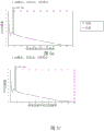
FIG. 3A: a type a energy profile between the far and near foci as a function of pupil size change designed for 3.0D add power bifocal; FIG. 3B: type B energy distribution of a 3.0D add power bifocal design between the far and near foci as a function of pupil size change.
FIG. 4 a: type a surface phase structure of a bifocal IOL having 3.0D add power (minus the baseline power); FIG. 4 b: type B surface phase structure of bifocal IOLs having 3.0D add power (minus the baseline power).
FIGS. 5a-5 h: the Modulation Transfer Function (MTF) of the 3.0D additive bifocal design for different pupil sizes and type a and type B energy profiles.
FIGS. 6a-6 d: image simulations of 3.0D additive bifocal designs for different pupil sizes and type a and type B energy distributions.
FIGS. 7a-7 d: simulation of through-focus (through-focus) performance of 3.0D add bifocal IOLs for different pupil sizes and type a and type B energy distributions.
FIGS. 8a-8 b: surface phase structure of trifocal IOLs with 1.5D and 3.0D add powers (minus the baseline power) for different pupil sizes and type a and type B energy profiles.
FIGS. 9a-9 b: 1.75D and 3.5D additional trifocal designed energy distributions between far, intermediate and near foci for different pupil sizes and type a and B energy distributions.
FIGS. 10a-10 f: the Modulation Transfer Function (MTF) of the trifocal type a design is added for 1.75D and 3.5D.
FIGS. 11a-11 b: imaging simulations for a trifocal design with 1.75D and 3.5D additive trifocal a-type designs.
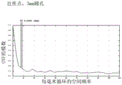
FIG. 12: simulation of defocus performance for trifocal IOL type a designs.
FIG. 13: surface phase structure of EDOF IOL with depth of focus exceeding 2.5D (minus baseline refractive power).
FIGS. 14A-14B: imaging simulations of the EDOF design and the conventional single focus IOL design.
FIG. 15: simulation of through focus MTF performance for EDOF IOLs and conventional monofocal IOLs.
FIG. 16: surface discrete phase structure of alternating trifocal IOLs (minus the baseline refractive power).
FIG. 17: simulation of the through-focus performance of an alternative trifocal IOL.
Detailed description of non-limiting, exemplary embodiments
The design method of the implemented IOL derives from the fluctuating nature of the light. According to Huygens' diffraction principle, light is described as a wave by wavelength, phase, and amplitude, and exhibits diffraction and interference phenomena as it propagates in/through/between media or media.
As shown in fig. 1, the lens 100 having a phase change characteristic can control diffraction and interference of light propagating therethrough to realize multiple focuses and EDOF. The discrete phase profiles are provided by structural step profiles 102 (top), each structural step profile 102 having a maximum step height h in the range (scale) of 0 to 2 wavelengths λ (where λ is the dominant IOL design wavelength). As shown in fig. 1 (bottom), each step profile 102 is incorporated into a respective plurality of m contiguous annular optical zones, each contiguous annular optical zone bounded by a radius rmIs defined on the surface of the lens and extends outwardly from the center of the lens to the periphery. The total effective optical area of the lens is defined as the combined area of the m optical zones.
The concentric annular region m is characterized by two main parameters, e.g. the position/radius r of the ringmAnd the height h of the sudden step jump (peak height phase deviation). These parameters were determined as follows:
radius r of mth ringmIs given by
rm=(2mλf)1/2 (1)
Where m is 0,1,2. (integer value), λ is the dominant IOL design wavelength, and f is the focal length corresponding to the "add power" of the intended multifocal lens; i.e., f-1000 mm/add power).
The step height h at the trailing circumferential edge of each annular optical zone is given by
Wherein Is the diffraction efficiency of the nth diffraction order (n is 0,1,2, 3.) and k is (n)2-n1) h/lambda is a factor for adjusting the phase jump, (n)2-n1) Is the refractive index difference between the medium (e.g., the user's eye, or if not implanted air) and the optical area (grating) material that the lens occupies, and h is the step height, which can be from a specified value
 And (6) solving.
Equation (2) describes the diffraction efficiency How to associate with each diffraction order (n) of interest in each annular optical zone m. Diffraction efficiency is a parameter that quantitatively describes how optical energy is distributed between different focal points (add powers) in each optical zone. This is schematically illustrated in fig. 2. In fig. 2, the 0 th, 1 st and 2 nd diffraction orders correspond to the base power (f) of the lens in each optical zone m0) A first additional focal power (f)1) And a second add power (f)2)。
In equation (2), f (r)m) Is an adjustment function for optimizing the light distribution in the available diffraction orders and minimizing the light spreading into the unavailable diffraction orders, and it provides flexibility to the surface profile of the mth diffraction zone, not limited to a sphere, but can be extended to an aspheric surface or a free shape. f (r)m) Related to the fourier transform of the exact phase profile of the m-th diffraction zone.
Equation (2) is derived from Fraunhofer diffraction calculations for generalized gratings, and in the embodied invention, each optical zone m is treated as a specific single partial grating.
The derivation of equations (1) and (2) is set forth in appendix 1 at the end of the description.
For the total optical area of the lens surface, different diffraction orders n (each individual diffraction order n, corresponding to each individual focus in each optical zone m)Point or add power) is treated as a weighted sum of the individual diffraction efficiencies in each local region (expressed as Where n represents a diffraction order and m represents an mth annular optical zone). The weighting factor is defined by the surface area ratio R between the individual optical zones and the total effective optical areamThe determination is as follows:

wherein Is the local diffraction efficiency of the m-th region, and
Rm(area of mth annular optical area)/(total effective (diffractive) optical area of IOL).
Diffraction efficiency via local optic zones in order to achieve a desired energy distribution among different focal points, or to achieve an extended depth of focus And a weighting factor RmTo optimize the surface phase profile. According to an exemplary embodiment, four methods summarized in table 1 below are used to design implemented diffractive, multifocal and/or EDOF lenses, examples of which are described below.
TABLE 1

In accordance with an illustrative embodiment, an optical modeling method is used to simulate the optical performance of an implemented IOL in an optical raytracing environment. The method involves creating an optical raytrace model eye that can simulate the optical performance of an eye having an IOL inserted in the model.
The method also involves constructing a user-defined surface that can be used to input discrete surface phase profiles in the optical raytracing model. The discrete phase surface profile is associated with a user-defined function that can adjust the phase parameters of each ray traced through the surface based on the designed local diffractive structure profile.
The method also relies on incoherent imaging frequency response analysis techniques to simulate the optical performance of the design. The basic theory is summarized in appendix 2 at the end of the description. Metrics used to evaluate optical image quality include Point Spread Function (PSF), Modulation Transfer Function (MTF), and imaging simulation. The method more particularly relates to the steps of: 1) tracking the rays with the phase parameters modified by the diffractive surface to the exit pupil of the ray tracking model and constructing a true pupil function; 2) obtaining an Optical Transfer Function (OTF) calculated as an autocorrelation of a pupil function based on ray tracing data at an exit pupil; 3) obtaining a Modulation Transfer Function (MTF), which is the modulation of the OTF, that describes image contrast degradation at various spatial frequencies from the object to the image; 4) obtaining MTFs at different defocus positions, which describe the designed defocus performance; 5) obtaining a system Point Spread Function (PSF) via an inverse fourier transform of the OTF; 6) the imaging simulation is performed by convolving the PSF with the object (inverse fourier transform of the product of the OTF and the object's spectrum).
Non-limiting embodiments include four exemplary IOL designs based on methods I-IV in Table I above, as follows.
Example 1 (method I)
Bifocal IOLs having an add power of 3.0 diopters (D) correspond to the far and near foci, respectively. The design has a diffractive structure with a uniform surface area ratio R for each diffractive regionmAnd the diffraction efficiency is uniformly (monotonously) decreased (i.e., the step height is uniformly (monotonously) decreased). Table 2 and fig. 3A-7 d disclose and show design parameters and performance predictions.
Bifocal IOLs employ a 3.0D add power design. This design format includes type a and type B designs. As shown in fig. 3A, the type a design has a consistent 45.5%/35.8% energy distribution between the far and near foci at all pupil sizes. As shown in fig. 3B, for the central 3mm region, pattern B has a uniform distance/near energy distribution of 45.5%/35.8%, and the energy distribution for pupil sizes greater than 3mm gradually varies uniformly, with more energy directed toward the far focus as the pupil size increases. Fig. 4a, 4b show discrete surface phase structures, and table 2 lists specified design parameters for ring position and step height at the trailing edge of the ring. The values specified in table 2 are particularly suitable for lens materials having a refractive index of 1.52 at a wavelength of 550 nm. For materials with other indices of refraction, the step height would need to be adjusted as follows:
h'=h*C,
C=0.184/(n'-1.336),
wherein
h 'is the adjusted step height for different refractive indices n',
h is the step height specified in table 2,
c is the adjustment coefficient of the optical fiber,
n is the refractive index of the material corresponding to table 2,
n' is the refractive index of the different materials. The design enabled for materials with refractive indices from 1.40-1.58.
TABLE 2 discrete surface structures of diffractive bifocal IOLs
Type A design

B-type design

The performance of the example 1IOL was evaluated by the modeling and analysis techniques implemented as disclosed above.
Figures 5a-5h show Modulation Transfer Functions (MTFs) (showing tangential and sagittal planes) with 3mm pupils (type a (figures 5a, 5e) and type B (figures 5B, 5f)) and 4.5mm pupils (type a (figures 5c, 5g) and type B (figures 5d, 5h)) at far and near foci.
Figures 6a-6 d show simulations for imaging at the retina of a model eye having a far focus and a near focus of two pupil sizes (3mm, 4.5 mm).
Figures 7a-7 d show simulated defocus MTF curves with two pupil sizes (3mm, 4.5 mm). Type a and type B are designed to have the same optical performance for a 3mm pupil; however, as the pupil becomes larger than 3mm, the type a (fig. 7a, 7B) design maintains consistent performance, while the type B (fig. 7c, 7d) design directs more light energy toward the far focus; for example, the MTF curve becomes higher at far focus and lower at near focus.
Example 2 (method II)
Trifocal IOLs having 1.75D and 3.5D add powers correspond to a far focus, an intermediate focus, and a near focus, respectively. This design has a diffractive structure with a uniform surface area ratio for each diffractive region, but with different diffraction efficiencies (alternating high and low step heights) for adjacent regions. Table 3 and fig. 8a-12 disclose and show design parameters and performance predictions.
The trifocal IOL is designed with two different add powers; e.g., 1.75D and 3.50D, to provide far, intermediate and near vision. Similar to example 1, the design form may include a-type and B-type designs. The type a design has a consistent energy distribution of 37.2%, 25.3%, and 23.7% between the far, intermediate, and near foci at all pupil sizes. Type B has a consistent distance/intermediate/near energy profile of 37.2%/25.3%/23.7% for only the central 3mm zone, but the energy profile is gradually changed as the pupil size increases from 3mm to 5mm, with the pupil size increasing more toward the distance and intermediate foci.
Fig. 8a, 8B show the discrete surface phase structures of type a and type B, respectively, and table 3 shows the specified design parameters for ring position and step height at the tail edge of the ring. The parameters specified in table 3 are particularly applicable to materials having a refractive index of 1.52 at a wavelength of 550 nm. For materials with other indices of refraction, the step height would need to be adjusted as follows:
h'=h*C,
C=0.184/(n'-1.336),
wherein
h 'is the adjusted step height for different refractive indices n',
h is the step height specified in table 3,
c is the adjustment coefficient of the optical fiber,
n is the refractive index of the material corresponding to table 3,
n' is the refractive index of the different materials. The design enabled for materials with refractive indices from 1.40-1.58.
TABLE 3 discrete surface Structure

The performance of the example 2IOL was evaluated by the modeling and analysis techniques implemented as disclosed above.
Fig. 9a, 9B show the energy distribution of far/intermediate/near focus for both type a and type B designs, respectively. Then, for the type a design, fig. 10a-10f show the Modulation Transfer Functions (MTFs) at far, intermediate and near focus (tangential and sagittal planes are shown).
Fig. 11a, 11b show simulations of imaging at the retina of a model eye for a far focus, an intermediate focus and a near focus with two pupil sizes (3mm, 5mm), respectively.
Fig. 12 shows simulated defocus MTF curves with two pupil sizes.
Example 3 (method III)
Extended depth of focus IOLs (edof IOLs) have a continuous depth of focus that extends to greater than 2.5D (compared to the 0.5D maximum of a conventional refractive IOL). The design form has a diffractive structure with a symmetrical dual blazed phase structure (back-to-back), a uniform surface area ratio, and a uniform maximum phase deviation within each diffractive region. Table 4 and fig. 13-15 disclose and show design parameters and performance predictions.
EDOF IOLs are designed to have a depth of focus that extends above 2.5D. Fig. 13 shows the discrete surface phase profile, and table 4 shows the specified design parameters for the ring position and step height at the trailing edge of the ring. The parameters specified in table 4 are particularly applicable to materials having a refractive index of 1.52 at a wavelength of 550 nm. For materials with other indices of refraction, the step height would need to be adjusted as follows:
h'=h*C,
C=0.184/(n'-1.336),
wherein
h 'is the adjusted step height for different refractive indices n',
h is the step height specified in table 4,
c is the adjustment coefficient of the optical fiber,
n is the refractive index of the material corresponding to table 4,
n' is the refractive index of the different materials. The design enabled for materials with refractive indices from 1.40-1.58.
TABLE 4 discrete surface Structure

The performance of the example 3IOL was evaluated by the modeling and analysis techniques implemented as disclosed above.
Fig. 14a, 14b show simulations for 3.0D depth of focus imaging at the retina of a model eye and for a monofocal IOL design without diffractive phase structures on the surface.
FIG. 15 shows simulated through focus MTF curves for an implemented EDOF design and a conventional monofocal IOL.
Example 4 (method IV)
Alternative trifocal designs provide far, intermediate, and near vision. The design employs a method of both varying area ratio and varying diffraction efficiency among the diffraction zones. Unlike the trifocal design disclosed in example 2, this design eliminates the gap from distance vision to intermediate vision (e.g., about 2.0D depth of focus at distance vision, which produces continuous vision from distance vision to intermediate vision), and also provides functional near vision. Table 5 and fig. 16-17 disclose and show design parameters and performance predictions.
This alternative trifocal optical design has two different add powers (e.g., 1.75D and 3.50D) to provide far, intermediate, and near vision. The design employs a method of both varying area ratio and varying diffraction efficiency among the diffraction zones. The goal of this design is to have continuous optical performance from far vision to intermediate vision (e.g., about 2.0D depth of focus at far vision) and also functional near vision.
Fig. 16 depicts a discrete surface phase structure, and table 5 depicts specified design parameters for ring position and step height at the trailing edge of the ring. The parameters specified in table 5 are particularly applicable to materials having a refractive index of 1.52 at a wavelength of 550 nm. For materials with other indices of refraction, the step height would need to be adjusted as follows:
h'=h*C,
C=0.184/(n'-1.336),
wherein
h 'is the adjusted step height for different refractive indices n',
h is the step height specified in table 5,
c is the adjustment coefficient of the optical fiber,
n is the refractive index of the material corresponding to table 5,
n' is the refractive index of the different materials. The design enabled for materials with refractive indices of 1.40-1.58.
TABLE 5 alternative discrete surface structures for trifocal design

The performance of the example 4IOL was evaluated by the modeling and analysis techniques implemented as disclosed above.
Fig. 17 shows the simulated through focus MTF curve, and unlike the trifocal design of example 2, there is no apparent MTF fluctuation from far focus to intermediate focus.
While several inventive embodiments have been described and illustrated herein, those of ordinary skill in the art will readily envision a variety of other means and/or structures for performing the function and/or obtaining one or more of the advantages and/or results described herein, and each of such variations and/or modifications is deemed to be within the scope of the inventive embodiments described herein. More generally, those skilled in the art will readily appreciate that all parameters, dimensions, materials, and configurations described herein are meant to be exemplary and that the actual parameters, dimensions, materials, and/or configurations will depend upon the specific application or applications for which the teachings of the present invention is/are used. Those skilled in the art will recognize, or be able to ascertain using no more than routine experimentation, many equivalents to the specific embodiments of the invention described herein. It is, therefore, to be understood that the foregoing embodiments are presented by way of example only and that, within the scope of the appended claims and equivalents thereto, embodiments of the invention may be practiced otherwise than as specifically described and claimed. Inventive embodiments of the present disclosure are directed to each individual feature, system, article, material, kit, and/or method described herein. In addition, any combination of two or more such features, systems, articles, materials, kits, and/or methods, if such features, systems, articles, materials, kits, and/or methods are not mutually inconsistent, is included within the scope of the present disclosure.
All definitions, as defined and used herein, should be understood to control dictionary definitions, definitions in documents incorporated by reference, and/or ordinary meanings of the defined terms.
The indefinite articles "a" and "an" as used in this specification and claims should be understood to mean "at least one" unless clearly indicated to the contrary.
The phrase "and/or" as used in this specification and claims should be understood to mean "one or two" of the elements so combined, i.e., the elements present in combination in some cases and present in isolation in other cases. The use of "and/or" listed elements should be construed in the same way, i.e., "one or more" elements so combined. Other elements may optionally be present in addition to elements specifically identified by the "and/or" clause, whether related or unrelated to those elements specifically identified. Thus, as a non-limiting example, when used in conjunction with open language such as "including," references to "a and/or B" may refer in one embodiment to only a (optionally including elements other than B); in another embodiment, reference is made to B only (optionally including elements other than a); in yet another embodiment, refer to both a and B (optionally including other elements); etc. of
As used in this specification and claims, "or" should be understood to have the same meaning as "and/or" as defined above. For example, when separating items in a list, "or" and/or "should be interpreted as being inclusive, i.e., a list that includes at least one, but also includes more than one, multiple elements, or elements, and optionally additional unlisted items. Only terms explicitly indicating the contrary, such as "only one" or "exactly one," or, when used in the claims, "consisting of" will refer to exactly one element of a list containing a plurality of elements or elements. In general, the term "or" as used herein, unless otherwise indicated herein, is to be construed as indicating an exclusive alternative (i.e., "one or the other but not both"), such as "either," "one of," "only one of," "exactly one of," or "consisting essentially of …," which when used in a claim, shall have its ordinary meaning as used in the patent law field.
As used in this specification and the claims, the phrase "at least one," in reference to a list of one or more elements, should be understood to mean at least one element selected from any one or more of the elements in the list of elements, but not necessarily including at least one of each element specifically listed in the list of elements, and not excluding any combinations of elements in the list of elements. This definition also allows that, in addition to the elements specifically identified within the list of elements referred to by the phrase "at least one," there may optionally be elements, whether related or unrelated to those elements specifically identified. Thus, as a non-limiting example, "at least one of a and B" (or, equivalently, "at least one of a or B," or, equivalently "at least one of a and/or B") may refer, in one embodiment, to at least one (optionally including more than one) a, with no B present (and optionally including elements other than B); in another embodiment, to at least one (optionally including more than one) B, a is absent (and optionally includes elements other than a); in yet another embodiment, to at least one (optionally including more than one) a and at least one (optionally including more than one) B (and optionally including other elements); and so on.
For the purposes of this disclosure, the term "about" as used herein and in the appended claims refers to an amount of a specified quantity plus/minus a typical and reasonable fractional amount or reasonable tolerance that one of ordinary skill in the art would consider to be for that particular quantity or measurement. Likewise, the term "substantially" means close to or similar to the specified term as modified, as those skilled in the art will recognize that this is typical and reasonable and is not intentionally different by design or implementation.
It will also be understood that, in any method claimed herein that includes more than one step or action, the steps of the method or the order of the steps are not necessarily limited to the order in which the steps or steps of the method are recited, unless specifically indicated to the contrary.
Appendix 1-theoretical derivation of equations (1) and (2)
Equation (1) is derived by using one of these two methods, which is detailed below:
One method of deriving the radius of the concentric regions is similar to that used in designing a Fresnel Phase Plate (Fresnel Phase Plate), where the Z position of maximum irradiance on the axis is set to the desired focus, and then the radius of the rings is solved from the maximum irradiance equation on the axis, the above calculations prove to be as follows:
the on-axis light intensity I is determined by the Fresnel number (N)f) Is determined as
I=2I0(1-Cos(Nf*π)),
Wherein:
I0is of constant intensity;
i is the on-axis light intensity corresponding to the exact z position;
Nfis the Fresnel number;
Nf=a2/λz=a2/λf.
when N is presentfAn on-axis intensity (I) reaches a maximum value at-2 m. -. 4, -2,0,2,4.. 2m (m · integer),
wherein:
a is the radius of the Fresnel zone;
λ is the wavelength;
z is the distance of the Z position;
f is the focal length.
The focal length (f) is made to correspond to the z-position of maximum irradiance on the axis. The radiation of the mth ring can be solved as amIs an integer √ 2m λ f, m ═ 0,1,2
A second method of deriving the radius of the annular diffraction zone is based on the grating equation of Fraunhofer diffraction, however, for a diffractive lens, each ring is treated as an independent local grating and the period of the local grating is made equal to the diameter of the ring, and the radius of the ring is solved according to the grating equation.
According to Fraunhofer diffraction theory, the grating equation is expressed as
mλ=Λm sin θm
Wherein:
Λmis the grating period of the m-th diffraction order;
Θ m is the deflection angle of the mth order diffraction of the ring of the diffractive lens. The radius of the mth ring corresponds to the mth annular region LambdamAnd the grating equation can be expressed as
mλ=(am 2+f2)1/2-f
=am2/2f.
Then, the user can use the device to perform the operation,
thus amIs an integer √ 2m λ f, m ═ 0,1,2.
Appendix 2-basic principles of the optical evaluation method of diffractive multifocal and EDOF lenses
Two main theories were used to establish the calculation and ray tracing methods for evaluating the optical performance of diffractive multifocal IOLs and EDOF IOLs. The established method will generate all optical performance simulation metrics, such as MTF, through focus MTF (tf MTF) and imaging simulation.
Theory 1: theory of coherent imaging
Coherent imaging being field-linear
Image plane UiThe field at (U, v) is the object plane Ug(u v) field and amplitude of coherent imaging system h (u, v)
Convolution of the degree impulse response;

the amplitude impulse response of the coherent imaging system is the fourier transform of the pupil function p (x, y);
h (u, v) ═ FT { p (x, y) }, at frequency fx、fyAs assessed herein.
The coherent image transfer function (or amplitude transfer function) is the FT of the PSF, so it is the rescaled pupil function
H(fu,fv)=P(-λZxpfu,-λZxpfv)
Theory 2: theory of incoherent imaging
Incoherent imaging is linear with irradiance. Human eye and light field Ii(u, v) or IgIrradiance response of (u, v).
Irradiance distribution at image plane is PSF (e.g., | h (u, v))2) And irradiance distribution of the object

The Optical Transfer Function (OTF) of incoherent imaging is the fourier transform of the PSF, which is mathematically equivalent to the autocorrelation of the amplitude transfer function according to a derivation using fourier transform theory, and the amplitude transfer function is proportional to the rescaled pupil function.

Claims (8)
1. A multifocal intraocular lens comprising:
a lens body having an anterior surface and a posterior surface, wherein at least one of the anterior surface and the posterior surface is characterized by a discrete phase profile comprising m adjacent annular diffractive optical zones, each adjacent annular diffractive optical zone characterized by a radius rmAnd at each corresponding rmStep height h ofmWherein the heights of adjacent steps are not equal, hm≠hm+1Wherein m is 0,1,2,3.,
wherein r ism=(2mλf)1/2Where λ is the design wavelength and f is the focal length corresponding to the selected add power for the multifocal intraocular lens, f 1000 mm/add power,
and wherein Is the diffraction efficiency of the nth diffraction order in a particular optical zone m corresponding to the nth add power in the particular optical zone m
 Wherein: k is (n)2-n1)hmλ is for adjusting the step height hmIn which n is2-n1Non-lens medium and lensA difference in refractive index between diffractive optical zone media, wherein the step height hmCan be specified from
 Determining, and wherein the total energy distribution over the total effective diffractive optical area of the multifocal intraocular lens
 Local diffraction efficiency expressed as a specific optical region m
 Wherein n is a weighted sum corresponding to the add power in the mth optical zonenN is 0,1,2,3, and f (r)m) Is an adjustment function for optimizing the light distribution in the usable diffraction orders and minimizing the light spreading into the unusable diffraction orders,
wherein the weighting factor is defined by the surface area ratio R between the individual optical area m and the total effective diffractive optical area of the multifocal intraocular lensmIs determined in which m is 1,2,3, n is 0,1,2,3, and
Rmthe area of the mth annular optical zone/total effective diffractive optical zone of the multifocal intraocular lens,
and wherein the discrete phase profile is via the local diffraction efficiency And the weighting factor RmAre optimized to achieve a desired energy distribution among different focal points, or to achieve an extended depth of focus.
2. A multifocal intraocular lens according to claim 1, characterized in that m is present for all said optical zones, Has a constant value, and for all said optical areas m, RmHas a constant value.
3. A multifocal intraocular lens according to claim 1, characterized in that for all the optical zones m, has a variable value and R for all of said optical areas m, RmHas a constant value.
4. A multifocal intraocular lens according to claim 1, characterized in that for all the optical zones m, has a constant value, and for all said optical areas m, RmWith variable values.
5. A multifocal intraocular lens according to claim 1, characterized in that for all the optical zones m, has a variable value and R for all of said optical areas m, RmWith variable values.
6. The multifocal intraocular lens of claim 1, wherein the adjustment function f (r)m) Related to the fourier transform of the exact phase profile of the m-th diffraction zone.
7. An optical modeling method for simulating optical performance of a selected multifocal intraocular lens of claim 1 in an optical ray tracing environment, the method comprising:
creating an optical ray tracing model eye capable of simulating the optical performance of an eye having a selected multifocal intraocular lens inserted in the model;
constructing a user-defined surface to input a discrete surface phase profile of the selected multifocal intraocular lens in the optical ray tracing model eye, wherein the discrete surface phase profile is associated with a user-defined function capable of adjusting a phase parameter of each ray traced through the surface based on a local diffractive structure profile.
8. The method of claim 7, further comprising:
tracking the rays with the phase parameters modified by the diffractive surface to the exit pupil of a ray tracking model and constructing a true pupil function;
determining an optical transfer function;
determining a modulation transfer function;
determining modulation transfer functions at different defocus positions, which describe the designed defocus performance;
determining a system point spread function; and is
And performing imaging simulation.
Applications Claiming Priority (5)
| Application Number | Priority Date | Filing Date | Title |
|---|---|---|---|
| US201662332186P | 2016-05-05 | 2016-05-05 | |
| US62/332,186 | 2016-05-05 | ||
| US201662332675P | 2016-05-06 | 2016-05-06 | |
| US62/332,675 | 2016-05-06 | ||
| PCT/US2017/029600 WO2017192333A1 (en) | 2016-05-05 | 2017-04-26 | Intraocular lens and associated design and modeling methods |
Publications (2)
| Publication Number | Publication Date |
|---|---|
| CN109477913A CN109477913A (en) | 2019-03-15 |
| CN109477913B true CN109477913B (en) | 2021-08-06 |
Family
ID=60203162
Family Applications (1)
| Application Number | Title | Priority Date | Filing Date |
|---|---|---|---|
| CN201780027799.5A Active CN109477913B (en) | 2016-05-05 | 2017-04-26 | Intraocular lenses and related design and modeling methods |
Country Status (5)
| Country | Link |
|---|---|
| US (1) | US20190142577A1 (en) |
| EP (1) | EP3452852A4 (en) |
| JP (1) | JP2019519346A (en) |
| CN (1) | CN109477913B (en) |
| WO (1) | WO2017192333A1 (en) |
Families Citing this family (14)
| Publication number | Priority date | Publication date | Assignee | Title |
|---|---|---|---|---|
| US11324588B2 (en) * | 2018-04-09 | 2022-05-10 | Mediphacos Industrias Medicas S/A | Diffractive intraocular lens |
| JP7568629B2 (en) * | 2018-09-13 | 2024-10-16 | ハニータ レンズ リミテッド | Multifocal intraocular lenses |
| US11327341B2 (en) * | 2019-06-14 | 2022-05-10 | Johnson & Johnson Vision Care, Inc | Toric contact lens stabilization design based on thickness gradients orthogonal to eyelid margin |
| CN110929375B (en) * | 2019-10-17 | 2021-08-31 | 中国科学院电子学研究所 | Efficient lens simulation and optimization method based on two-dimensional moment method and ray tracing method |
| CN113939251B (en) * | 2019-10-23 | 2023-06-09 | 东莞东阳光医疗智能器件研发有限公司 | Ophthalmic lens |
| WO2021127033A1 (en) * | 2019-12-16 | 2021-06-24 | Arizona Board Of Regents On Behalf Of The University Of Arizona | Segmented optical components and methods |
| AU2021283398A1 (en) | 2020-06-01 | 2023-01-05 | Icares Medicus, Inc. | Double-sided aspheric diffractive multifocal lens, manufacture, and uses thereof |
| US20240142790A1 (en) * | 2021-02-05 | 2024-05-02 | Arizona Board Of Regents On Behalf Of The University Of Arizona | Devices and methods for performing high-harmonic diffractive lens color compensation |
| US20240307170A1 (en) * | 2021-02-19 | 2024-09-19 | Vsy Biyoteknoloji Ve Ilac Sanayi A.S. | An adaptive multifocal diffractive ocular lens |
| EP4115850A1 (en) * | 2021-07-05 | 2023-01-11 | Nidek Co., Ltd. | Intraocular lens |
| CN114624878B (en) * | 2022-03-24 | 2024-03-22 | 深圳迈塔兰斯科技有限公司 | Method and device for designing optical system |
| WO2023204621A1 (en) * | 2022-04-21 | 2023-10-26 | 한양대학교 산학협력단 | Composite diffractive multifocal intraocular lens |
| CN114781187B (en) * | 2022-05-31 | 2024-10-11 | 南开大学 | Optimization method for smooth phase multifocal intraocular lens design |
| CN116747048B (en) * | 2023-08-18 | 2023-11-17 | 微创视神医疗科技(上海)有限公司 | Intraocular lens |
Family Cites Families (5)
| Publication number | Priority date | Publication date | Assignee | Title |
|---|---|---|---|---|
| US20070182917A1 (en) * | 2006-02-09 | 2007-08-09 | Alcon Manufacturing, Ltd. | Intra-ocular device with multiple focusing powers/optics |
| US20080269885A1 (en) * | 2007-04-30 | 2008-10-30 | Simpson Michael J | IOL Peripheral Surface Designs to Reduce Negative Dysphotopsia |
| EP2396683B1 (en) * | 2009-02-12 | 2020-04-08 | The Arizona Board Of Regents On Behalf Of The University Of Arizona | Diffractive trifocal lens |
| WO2012074742A1 (en) * | 2010-11-30 | 2012-06-07 | Amo Groningen Bv | Method for designing, evaluating and optimizing ophthalmic lenses and laser vision correction |
| AU2013355144B2 (en) * | 2012-12-06 | 2018-07-05 | Johnson & Johnson Surgical Vision, Inc. | System and method for evaluating intraocular lens performance |
-
2017
- 2017-04-26 EP EP17793022.9A patent/EP3452852A4/en not_active Withdrawn
- 2017-04-26 CN CN201780027799.5A patent/CN109477913B/en active Active
- 2017-04-26 JP JP2019510760A patent/JP2019519346A/en active Pending
- 2017-04-26 US US16/097,390 patent/US20190142577A1/en not_active Abandoned
- 2017-04-26 WO PCT/US2017/029600 patent/WO2017192333A1/en unknown
Also Published As
| Publication number | Publication date |
|---|---|
| CN109477913A (en) | 2019-03-15 |
| EP3452852A4 (en) | 2020-04-15 |
| EP3452852A1 (en) | 2019-03-13 |
| US20190142577A1 (en) | 2019-05-16 |
| JP2019519346A (en) | 2019-07-11 |
| WO2017192333A1 (en) | 2017-11-09 |
Similar Documents
| Publication | Publication Date | Title |
|---|---|---|
| CN109477913B (en) | Intraocular lenses and related design and modeling methods | |
| JP2019519346A5 (en) | ||
| JP7346523B2 (en) | Multifocal lenses with reduced visual impairment | |
| US11721002B2 (en) | Imaging system and method for imaging objects with reduced image blur | |
| US7812295B2 (en) | Optical system and method for multi-range and dual-range imaging | |
| RU2501054C2 (en) | Accommodative intraocular lens (iol) having toric optical element and extended focal depth | |
| JP5203160B2 (en) | Diffractive multifocal lens | |
| US5344447A (en) | Diffractive trifocal intra-ocular lens design | |
| AU2012314904B2 (en) | Lens having an extended focal range | |
| RU2007124577A (en) | APODIZED ASPH. DIFFRACTION LENSES | |
| US20140293426A1 (en) | Lens with an Extended Range of Focus | |
| KR20140121815A (en) | Apodized hybrid diffractive-refractive iol for pseudo-accommodation | |
| WO2016021075A1 (en) | Diffractive multi-focal lens and method for manufacturing diffractive multi-focal lens | |
| JPWO2013118177A1 (en) | Diffractive multifocal ophthalmic lens and manufacturing method thereof | |
| CN101422392A (en) | Zonal diffractive multifocal intraocular lenses | |
| JP2015536796A (en) | Method and system for providing an intraocular lens with improved depth of field | |
| WO2014091528A1 (en) | Diffractive multifocal ophthalmic lens and production method thereof | |
| BR112021004895A2 (en) | multifocal intraocular lens | |
| US20190041664A1 (en) | Ophthalmic diffractive multi-focal lens and method for manufacturing ophthalmic diffractive multi-focal lens | |
| CN115024859B (en) | Multifocal intraocular lens with smooth phase distribution | |
| Nemes-Czopf et al. | Simulation of relief-type diffractive lenses in ZEMAX using parametric modelling and scalar diffraction | |
| Ramos-López et al. | Computational aspects of the through-focus characteristics of the human eye | |
| US20240335277A1 (en) | Full-visual range intraocular lens | |
| CN116747048B (en) | Intraocular lens | |
| de Carvalho et al. | Design of diffractive multifocal intraocular lenses |
Legal Events
| Date | Code | Title | Description |
|---|---|---|---|
| PB01 | Publication | ||
| PB01 | Publication | ||
| SE01 | Entry into force of request for substantive examination | ||
| SE01 | Entry into force of request for substantive examination | ||
| GR01 | Patent grant | ||
| GR01 | Patent grant | ||
| TR01 | Transfer of patent right |
Effective date of registration: 20221230 Address after: No. 28, Floor 7, Unit A, Building 1, No. 8, Guohuai Street, High tech Industrial Development Zone, Zhengzhou, Henan Patentee after: Henan saimeishi Biotechnology Co.,Ltd. Address before: Illinois, USA Patentee before: PILLAR BIOSCIENCE LLC |
|
| TR01 | Transfer of patent right |