EP2396628B1 - Magnetostriktiver positionswandler mit mehreren flachspulen - Google Patents
Magnetostriktiver positionswandler mit mehreren flachspulen Download PDFInfo
- Publication number
- EP2396628B1 EP2396628B1 EP09787646A EP09787646A EP2396628B1 EP 2396628 B1 EP2396628 B1 EP 2396628B1 EP 09787646 A EP09787646 A EP 09787646A EP 09787646 A EP09787646 A EP 09787646A EP 2396628 B1 EP2396628 B1 EP 2396628B1
- Authority
- EP
- European Patent Office
- Prior art keywords
- printed circuit
- circuit board
- transducer
- results
- flat coils
- Prior art date
- Legal status (The legal status is an assumption and is not a legal conclusion. Google has not performed a legal analysis and makes no representation as to the accuracy of the status listed.)
- Active
Links
- 230000026683 transduction Effects 0.000 claims description 28
- 238000010361 transduction Methods 0.000 claims description 28
- 230000005284 excitation Effects 0.000 claims description 13
- 230000000694 effects Effects 0.000 claims description 8
- 238000012545 processing Methods 0.000 claims description 7
- 238000004804 winding Methods 0.000 claims description 5
- 239000004020 conductor Substances 0.000 claims description 3
- 230000003993 interaction Effects 0.000 claims description 2
- 238000001514 detection method Methods 0.000 description 16
- 238000005259 measurement Methods 0.000 description 11
- 238000009826 distribution Methods 0.000 description 6
- 239000010410 layer Substances 0.000 description 5
- 239000000463 material Substances 0.000 description 5
- 239000002184 metal Substances 0.000 description 5
- 229910052751 metal Inorganic materials 0.000 description 5
- 230000001902 propagating effect Effects 0.000 description 5
- 238000007667 floating Methods 0.000 description 4
- RYGMFSIKBFXOCR-UHFFFAOYSA-N Copper Chemical compound [Cu] RYGMFSIKBFXOCR-UHFFFAOYSA-N 0.000 description 3
- 238000010276 construction Methods 0.000 description 3
- 238000004519 manufacturing process Methods 0.000 description 3
- 238000012423 maintenance Methods 0.000 description 2
- 239000003550 marker Substances 0.000 description 2
- 229910000990 Ni alloy Inorganic materials 0.000 description 1
- XUIMIQQOPSSXEZ-UHFFFAOYSA-N Silicon Chemical compound [Si] XUIMIQQOPSSXEZ-UHFFFAOYSA-N 0.000 description 1
- 230000006978 adaptation Effects 0.000 description 1
- 238000004026 adhesive bonding Methods 0.000 description 1
- 230000003321 amplification Effects 0.000 description 1
- 238000007796 conventional method Methods 0.000 description 1
- 229910052802 copper Inorganic materials 0.000 description 1
- 239000010949 copper Substances 0.000 description 1
- 230000008878 coupling Effects 0.000 description 1
- 238000010168 coupling process Methods 0.000 description 1
- 238000005859 coupling reaction Methods 0.000 description 1
- 238000002788 crimping Methods 0.000 description 1
- 238000010586 diagram Methods 0.000 description 1
- 230000005489 elastic deformation Effects 0.000 description 1
- 239000011810 insulating material Substances 0.000 description 1
- 239000007769 metal material Substances 0.000 description 1
- 238000012986 modification Methods 0.000 description 1
- 230000004048 modification Effects 0.000 description 1
- 238000003199 nucleic acid amplification method Methods 0.000 description 1
- 230000009467 reduction Effects 0.000 description 1
- 230000035945 sensitivity Effects 0.000 description 1
- 230000019491 signal transduction Effects 0.000 description 1
- 229910052710 silicon Inorganic materials 0.000 description 1
- 239000010703 silicon Substances 0.000 description 1
- 239000002210 silicon-based material Substances 0.000 description 1
- 239000002356 single layer Substances 0.000 description 1
- 238000003466 welding Methods 0.000 description 1
Images


Classifications
-
- G—PHYSICS
- G01—MEASURING; TESTING
- G01D—MEASURING NOT SPECIALLY ADAPTED FOR A SPECIFIC VARIABLE; ARRANGEMENTS FOR MEASURING TWO OR MORE VARIABLES NOT COVERED IN A SINGLE OTHER SUBCLASS; TARIFF METERING APPARATUS; MEASURING OR TESTING NOT OTHERWISE PROVIDED FOR
- G01D5/00—Mechanical means for transferring the output of a sensing member; Means for converting the output of a sensing member to another variable where the form or nature of the sensing member does not constrain the means for converting; Transducers not specially adapted for a specific variable
- G01D5/48—Mechanical means for transferring the output of a sensing member; Means for converting the output of a sensing member to another variable where the form or nature of the sensing member does not constrain the means for converting; Transducers not specially adapted for a specific variable using wave or particle radiation means
- G01D5/485—Mechanical means for transferring the output of a sensing member; Means for converting the output of a sensing member to another variable where the form or nature of the sensing member does not constrain the means for converting; Transducers not specially adapted for a specific variable using wave or particle radiation means using magnetostrictive devices
Definitions
- the present invention relates to a position transducer, and particularly to a magnetostrictive position transducer.
- a position transducer of the magnetostrictive type is typically employed in those application fields in which a highly accurate detection of absolute position is required, for example, in the field of tools machines or ground handling machines.
- magnetostrictive position transducer As it is known, a magnetostrictive position transducer, hereinafter also simply referred to as magnetostrictive transducer, is arranged for the measurement of a position by means of a magnetic-type position marker (permanent magnet), i.e., a magnetic cursor which is floating relative to the magnetostrictive transducer.
- a magnetic-type position marker permanent magnet
- a magnetostrictive transducer of the known type is composed of an outer metal profile which constitutes the shell of the very magnetostrictive transducer, which houses a waveguide of magnetostrictive material therein.
- An excitation current pulse is made to flow on the waveguide or on a copper conductive wire coaxial to the same waveguide, such as to induce a magnetic field having circular symmetry around the waveguide.
- the magnetic cursor results to be arranged so as to determine the measurement of the absolute position (measurement point) of the magnetostrictive transducer operative zone.
- the magnetic cursor is implemented so that the lines of the magnetic field associated thereto result to be perpendicular to the magnetic field induced by the excitation current pulse.
- the magnetic field associated to the magnetic cursor, and the magnetic field induced by the excitation current pulse interact, and induce a torsional elastic deformation on the waveguide by magnetostrictive effect.
- Such deformation is realized in a torsional mechanical wave (typically of the helical elastic type) propagating starting from the measurement point in the two longitudinal directions of the same waveguide.
- the propagation of the torsional mechanical wave is dampened by suitable mechanical dampeners, while, at the opposite end, the torsional mechanical wave is detected by a detection solenoid coil coupled to the circular tube, and converted to an electrical signal.
- the time elapsed between the sending of the excitation current pulse in the waveguide and the detection of the torsional mechanical wave passage on the detection coil is the quantity measured by the magnetostrictive transducer, and it is proportional to the relative distance between the mobile magnetic cursor (measurement point) and the detection coil (reference point).
- the magnetostrictive transducer of the known type described above has the drawback to result to be quite complex and cumbersome, especially as regards the detection solenoid coil. This drawback affects the construction times of the magnetostrictive transducer, and inevitably also the production costs of the same transducer.
- Object of the present invention is to devise and provide a magnetostrictive position transducer which allows at least partially obviating the drawbacks described above with reference to the prior art.
- a magnetostrictive position transducer or simply magnetostrictive transducer, is now described, generally indicated with the reference numeral 1, according to an example of the invention.
- the magnetostrictive transducer 1 comprises an outer metal profile 2 representing the housing shell of the very magnetostrictive transducer 1.
- the magnetostrictive transducer 1 comprise a first magnetostrictive transduction member 3, for example, a waveguide of magnetostrictive material, for example, a nickel alloy, housed within the outer metal profile 2.
- a first magnetostrictive transduction member 3 for example, a waveguide of magnetostrictive material, for example, a nickel alloy, housed within the outer metal profile 2.
- the waveguide 3 results to be preferably housed within a per se known sheath 3' (shown only in a portion in Fig. 1 ).
- the waveguide 3 results to be a wire of magnetostrictive material.
- the waveguide can be a tube of magnetostrictive material having a circular cross-section, or a bar having a different cross-section, for example, squared, rectangular, polygonal, oval, and so on.
- the waveguide 3 is arranged for the conduction and transport of an excitation current pulse from an end (where the excitation current pulse is inputted) to the other one of the waveguide 3;
- the magnetostrictive transducer 1 further comprises a conduction member (for example, a copper wire) operatively associated to the waveguide 3 for the conduction of the excitation current pulse from an end to the other one of the waveguide 3 (tube of circular cross-section).
- a conduction member for example, a copper wire
- such conduction member results to be housed within the waveguide 3 of magnetostrictive material.
- the magnetostrictive transducer 1 of the described example in Fig. 1 further comprises a second conduction member 4 (for example, a copper wire) representative of an excitation current pulse return path.
- a second conduction member 4 for example, a copper wire
- the waveguide 3 also as a first conduction member, results to be representative of the excitation current pulse outward path.
- the magnetostrictive transducer 1 further advantageously comprises a connecting conduction member 5 electrically associated both to the waveguide 3 and to the second conduction member 4 preferably arranged at the end of the outer metal tube 2 opposite the end into which the current pulse is inputted in the waveguide 3.
- Such connecting conduction member 5 can be any conventional electric connection elements such as, for example, a metal material track on a printed circuit board, a length of a metallic wire suitably welded, or a direct weld or electric contact obtained by a crimping operation between waveguide 3 and second conduction member 4.
- the magnetostrictive transducer 1 further comprises, at the end of the outer metal tube 2 at which the connecting conduction member 5 is arranged, dampeners 6, preferably of silicon material, arranged in contact with the waveguide 3.
- dampeners 6 act so as to dampen the torsional mechanical waves propagating along the waveguide 3 to the opposite end relative to the one at which the mechanical waves, as will be described below, are actually subjected to a detection and transduction.
- the magnetostrictive transducer 1 further comprises a second transduction member 7, operatively associated to the waveguide 3 (first transduction member), for a physical signal generated by magnetostrictive effect by the transduction member 3.
- a torsional elastic mechanical wave for example, of the helical type, propagating in the waveguide 3. It is pointed out that a magnetic field propagating in the waveguide and around it, which accompanies the same torsional mechanical wave is associated to such torsional mechanical wave by magnetostrictive effect.
- the second transduction member 7 comprises a plurality of flat coils (not shown in Fig. 1 ) distributed in a first printed circuit board 8.
- printed circuit board it is meant a monolayer or multilayer, rigid or flexible, support of insulating material, provided with tracks of conductive material.
- the first printed circuit board 8 results to be operatively associated to a second printed circuit board 8' which results to be arranged parallel to the longitudinal extent of the magnetostrictive transducer 1. It shall be noted that the waveguide 3 and the second conduction member 4 result to be electrically connected to the second printed circuit board 8'.
- first printed circuit board 8 The characteristics of the first printed circuit board 8, the second printed circuit board 8', and the possible arrangements of the waveguide 3 and the second conduction member 4 relative to the first printed circuit board 8, will be described herein below in the following present description.
- the second transduction member 7 (shown partially in Figs. 2 and 3 ) comprises a plurality of flat coils 9 distributed on more planes of the first printed circuit board 8 (in the example of the multilayer Figures) so that the coils result to be mutually aligned coaxially.
- the plurality of coils 9 in the example of Figs. 2 and 3 comprises a first flat coil 10 arranged on an upper face 11 of the printed circuit board 8, a second flat coil 20 arranged on a lower face 12 of the printed circuit board 8, and a plurality of inner coils 30 to the printed circuit board 8.
- the predetermined number of coils of the plurality of inner coils 30 results to be as a function of the number of layers of the multilayer printed circuit board, preferably ranging between 2 and 14 layers.
- the first printed circuit board 8 results to have four layers, and the plurality of coils interne 30 comprises two flat coils.
- Such distribution of the plurality of flat coils 9 advantageously allows increasing the detection sensitivity of the physical signal.
- the plurality of flat coils 9 can comprise, in combination or as an alternative, more than one flat coil distributed on the same plane for each inner layer of the first printed circuit board 8, for the upper face 11 and for the lower face 12 of the first printed circuit board 8.
- Some distribution examples of the plurality of flat coils on a same plane are: distribution only on the upper face of the first printed circuit board 8; distribution only on the first printed circuit board 8 lower face 12; distribution on both the upper 11 and the lower 12 faces of the first printed circuit board 8; flat distribution within one or more layers of the first (multilayer) printed circuit board 8.
- each coil (for example, the first flat coil 10) comprises a conductive material track arranged according to a spiral type winding.
- spiral type winding can have, alternatively, a polygonal or circular shape, or a shape comprising rectilinear lengths and curvilinear lengths (as in Figs. 2 and 3 ).
- polygonal shape it is meant a squared, rectangular, hexagonal, pentagonal geometrical shape, and so on.
- the second transduction member 7 comprises the first printed circuit board 8, comprising the plurality of flat coils 9, and the second printed circuit board 8'.
- the second printed circuit board 8' results to be arranged within the magnetostrictive transducer 1 so as to result to be parallel to the longitudinal extent of the waveguide 3.
- the first printed circuit board 8 results to be operatively associated to the second printed circuit board 8' in such a manner as to orient the plurality of flat coils 9 normally to the second printed circuit board 8' and to the longitudinal extent of the waveguide 3.
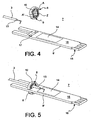
- the second printed circuit board 8' results to be provided with an opening 17 ( fig. 4 ) adapted to receive the first printed circuit board 8.
- the ultimate coupling between the first printed circuit board 8 and the second printed circuit board 8' can be obtained with conventional methods such, for example, glueing or welding.
- the first printed circuit board 8 can have such a configuration as to promote a snap-fitting thereof within the opening 17 which the second printed circuit board 8' is provided with.
- the plurality of flat coils 9 results to be operatively associated to a first preamplification electric circuit 14 (schematically indicated in the Figures with a rectangle) of the electrical signal detected and transduced by the plurality of flat coils 9.
- the first preamplification electric circuit 14 results to be preferably arranged on an upper face 15 of the second printed circuit board 8'.
- the first preamplification electric circuit 14 can be manufactured on a lower face 16 of the second printed circuit board 8'.
- the first preamplification electric circuit 14 can comprise a first portion and a second portion manufactured on the upper face 15 of the second printed circuit board 8' and on the lower face 16 of the second printed circuit board 8', respectively.
- Such embodiment advantageously allows further reducing the dimensions of the second printed circuit board 8'.
- the first printed circuit board 8 results to be provided with a first through opening A so arranged as to be passed through by a terminal portion 13 of the waveguide 3.
- Such first through opening A results to be arranged within a zone Z circumscribed by the plurality of flat coils 9 (in the above-mentioned Figures, the zone circumscribed by the first flat coil 10).
- first printed circuit board 8 results to be provided with a second through opening A' (visible only in Fig. 4 ) arranged within the circumscribed zone Z in order to be passed through by the second conduction member 4 (not shown in the Figures 4 and 5 ) .
- such second through opening A' can be obtained outside the plurality of flat coils 9.
- the first printed circuit board 8 results to be operatively coupled to the second printed circuit board 8' so that the waveguide 3 is facing the upper face 15 of the second printed circuit board 8', and the second conduction member is facing the lower face 16 of the second printed circuit board 8'.
- the first printed circuit board 8 can be coupled to the second printed circuit board 8' so that the waveguide 3 and the second conduction member result to be both facing the upper face 15 or lower face 16 of the second printed circuit board 8'.
- the first printed circuit board 8 results to be arranged so as to be operatively coupled to the second printed circuit board 8' so that the first printed circuit board 8 (and the plurality of flat coils 9) results to be normal to the second printed circuit board 8'.
- the first printed circuit board 8 can be so arranged as to be coupled to the second printed circuit board 8', so that the first printed circuit board 8 (and the plurality of flat coils 9) results to be inclined relative to the second printed circuit board 8' by a predetermined inclination angle different from 90°.
- the magnetostrictive transducer 1 similarly to the embodiment described above, comprises a second transduction member 7 comprising a plurality of flat coils 9 distributed in a first printed circuit board 8.
- the plurality of flat coils 9, as already described with reference to the Figs. 2 and 3 comprises a first flat coil 10 arranged on an upper face 11 of the first printed circuit board 8.
- the plurality of flat coils 10 can comprise a plurality of inner coils to the first printed circuit board (not shown in Fig. 6 ) and/or a further flat coil arranged on a first printed circuit board 8 lower face 12.
- the first printed circuit board 8 results to be preferably oriented so that the upper face 11 of the first printed circuit board 8 results to be parallel to the longitudinal extent of the magnetostrictive transducer 1, and particularly to the longitudinal extent of a first transduction member 3 (waveguide) which the magnetostrictive transducer is provided with.
- the first printed circuit board results to be arranged so that the plurality of flat coils 9 (particularly the first flat coil 10) results to be facing the longitudinal extent of a terminal portion 13 of the waveguide 3.
- the plurality of flat coils 9 results to be operatively associated to a first preamplification electric circuit 14 of the electrical signal detected and transduced by the plurality of flat coils 9, also implemented on the printed circuit board 8.
- the first electric circuit 14 is completely similar to the one described before with reference to the Figures 4 and 5 .
- the first electric circuit 14 results to be arranged on the upper face 11 of the first printed circuit board 8, but it can also be distributed on the first printed circuit board 8 according to the alternative modes already described before with reference to the Figures 4 and 5 .
- the first preamplification electric circuit 14 and the plurality of flat coils 9 are arranged one to the other so as to reduce noise and resistance effects between the wires employed for the electrical connection between the various components.
- the first electric circuit 14 and the plurality of flat coils 9 can be manufactured on the same support (first printed circuit board 8).
- the first electric circuit 14 and the plurality of flat coils 9 can be instead manufactured on different supports, but equally mutually electrically connected at a distance such as to reduce the above-mentioned noise and resistance effects.
- the first printed circuit board 8 can be oriented so that the upper face 11 of the first printed circuit board 8 results to be normal to the longitudinal extent of the magnetostrictive transducer 1, and particularly to the longitudinal extent of the waveguide 3 which the magnetostrictive transducer 1 is provided with.
- the first printed circuit board results to be arranged so that the plurality of flat coils 9 (particularly the first flat coil 10) results to be facing the longitudinal extent of a terminal portion 13 of the waveguide 3.
- the first printed circuit board 8 can be also provided with a first through opening A so arranged as to be passed through by a terminal portion 13 of the waveguide 3, and a second through opening A' so arranged as to be passed through by the second conduction member 4.
- Such first and second through openings are completely similar to those described above with reference to the Figures 4 and 5 .
- first A and the second A' through openings can take on the first printed circuit board 8 relative to the plurality of flat coils 9 are completely similar to those described above.
- the second transduction member 7 of the magnetostrictive transducer 1 results to be arranged so as to be operatively connected to a second processing electric circuit (not shown in the Figures) of the electrical signal pre-amplified by the first electric circuit 14.
- the second processing electric circuit can be implemented on the first printed circuit board 8 (for example, in the embodiment of Fig. 6 ) or on the second printed circuit board 8' (in the embodiment of Figs. 4 and 5 ).
- the second processing electric circuit (not shown in the Figures) can also be implemented on a further printed circuit board arranged in a remote position relative to the magnetostrictive transducer 1.
- the first preamplification electric circuit 14 comprises a per se known transconductance amplifier AMP, electrically associated to the plurality of flat coils 9 to receive the electrical signal therefrom representative of the detected physical signal transduction.
- the transconductance amplifier AMP results to be provided with a supply terminal TA to receive a voltage-adjusted supply signal and with an output terminal TU to provide a pre-amplified electrical signal.
- the plurality of flat coils 9 detects magnetic phenomena occurring in the terminal portion 13 of the waveguide 3.
- the torsional mechanical wave (physical signal) propagating within the waveguide 3 is generated by magnetostrictive effect by the interaction between a magnetic field associated to a floating magnetic cursor (not shown in the Figures) associable to the magnetostrictive transducer 1, and a magnetic field induced on the waveguide 3 by the excitation current pulse.
- the floating magnetic cursor is arranged where the position measurement is desired.
- the plurality of flat coils 9 is arranged for the detection of the passage in the terminal portion 13 of the waveguide 3 of the physical signal represented by the torsional mechanical wave.
- the plurality of flat coils 9 transduces the corresponding physical signal into an electrical signal, which is processed by the first preamplification electric circuit 14 and the second signal processing electric circuit.
- the electrical signal is representative of the count stop moment of the measurement period.
- measurement period it is meant the time elapsed between the start of the excitation current pulse in the transduction member 3 and the detection by the plurality of flat coils 9 of the physical signal representative of the torsional mechanical wave generated by magnetostrictive effect and the respective transduction thereof into an electrical signal.
- the measurement period is proportional to the relative distance between the measurement point represented by the floating magnetic cursor and the plurality of flat coils 9.
- the plurality of flat coils 9 as a second transduction member, it can be employed both in a closed circuit (detection of the physical signal under current) and in an open circuit (detection of the physical signal under voltage).
- the plurality of flat coils 9 is arranged to provide an electrical signal coming from the first preamplification electric circuit 14.
- the physical signal detection can occur according to one of the above-mentioned modes.
- the plurality of flat coils 9 is electrically connected to the inlet of a transresistance amplifier.
- the plurality of flat coils 9 is so arranged as to be passed through by an electric current representative also of the output signal of the plurality of flat coils 9.
- the plurality of flat coils 9 is electrically connected to the inlet of a high input impedance voltage amplifier (therefore, it is not so arranged as to be passed through by a current).
- the electric voltage generated at the ends of the plurality of flat coils 9 is representative also of the output signal of the same coil.
- the object of the invention is fully achieved, since the manufacturing of the plurality of flat coils on a printed circuit board allows reducing the construction and maintenance costs for the magnetostrictive position transducer.
- the manufacturing of a plurality of flat coils on a printed circuit board advantageously allows increasing the reproducibility of the same coil and to have, in the event of a failure of the coil, of a quite identical coil.
- an optional maintenance step which provides for the replacement of the flat coil results to be simple and fast, since it is sufficient to replace the printed circuit board.
Landscapes
- Physics & Mathematics (AREA)
- General Physics & Mathematics (AREA)
- Length Measuring Devices Characterised By Use Of Acoustic Means (AREA)
Claims (17)
- Magnetostriktiver Positionswandler (1), umfassend:- ein erstes Wandlungselement der magnetostriktiven Art (3);- ein zweitens Wandlungsefement (7), welches betriebsmäßig dem ersten Wandlungselement (3) zugeordnet ist, zum Empfangen eines physikalischen Signals, welches durch einen magnetostriktiven Effekt von dem ersten Wandlungselement (3) erzeugt wirt auf den Durchgang eines Anregungsstromimpulses hin durch die Winkung der Wechselwirkung zwischen einem Magnetfeld, welches einem magnetischen Zeigen zugeordnet ist, der dem magnetostriktiven Wandler (1) und einem durch den Anregungstromimpuls induzierten Magnetfeld zugeordnet sein kann;wobei der magnetostriktive Wandler (1) dadurch gekennzeichnet ist, dass das zweite Wandlungselement (7) eine Mehrzahl von Flachspulen (9) umfasst, welche in einer ersten Leiterplatte (8) verteilt sind.
- Wandler (1) nach Anspruch 1, wobei die Mehrzahl von Flachspulen (9) eine erste Flachspule (10) umfasst, welche an einher oberen Fläche (11) der ersten Leiterplatte (8) angeordnet ist.
- Wandler (1) nach Anspruch 2, wobei die Mehrzahl von Flachspulen (9) ferner eine zweite Flachspule (20) umfasst, welche an einer unteren Fläche (12) der ersten Leiterplatte (8) angeordnet ist.
- Wandler (1) nach Anspruch 3, wobei die Mehrzahl von Flachspulen (9) ferner eine Mehrzahl von inneren Flachspulen (30) zu der ersten Leiterplatte (8) umfasst, wodurch sich für die erste Flachspule (10), die zweite Flachspule (20) und die Mehrzahl von inneren Flachspulen (30) ergibt, gegenseitig koaxial ausgerichtet zu sind.
- Wandler (1) nach Anspruch 1, wobei das zweite Transduktionelement (7) ferner eine zweite Leiterplatte (8') umfasst.
- Wandler (1) nach Anspruch 5, wobei sich für die erste Leiterplatte (8) ergibt, betriebsmäßig der zweiten Leiterplatte zugeordnet zu sein, so dass sich für die Mehrzahl von Flachspulen (9) ergibt, orthogonal zu einem Endabschnitt (13) des ersten Wandlungselements (3) zu verlaufen .
- Wandler (1) nach Anspruch 6, wobei sich für die erste (8) und die zweite (8') Leiterplatte ergibt, betriebsmäßig einander zugeordnet zu sein, so dass sich für die erste Leiterplatte (8) ergibt, im Wesentlichen orthogonal zur zweiten Leiterplatte (8') zu verlaufen.
- Wandler (1) nach Anspruch 5, wobei sich für die erste (8) und die zweite (8') Leiterplatte ergibt, betriebsmäßig einander zugeordnet zu sein, so dass sich für die erste Leiterplatte (8') ergibt, relativ zur zweiten Leiterplatte (8') um einen vorbestimmten Neigungswinkel geneigt zu sein.
- Wandler (1) nach Anspruch 5, wobei sich für die erste Leiterplatte (8) ergibt, mit einer ersten Durchgangsöffnung (A) bei einher vor der Mehrzahl von Flachspulen (9) umschriebenen Zone (Z) bereitgestellt zu sein, wobei die erste Durchgangsöffnung angeordnet ist, um von einem Endabschnitt (13) des ersten Wandlungselements (3) durchdringen zu sein.
- wandler (1) nach Anspruch 9, wobei sich für die erste Leiterplatte (8) ergibt, ferner mit einer zweiten Durchgangsöffnung (A') bereitgestellt zu sein, welche bei der von der Mehrzahl von Flachspulen (9) umschriebenen Zone (Z) angeordnet ist, wobei der magnetostriktive Wandler (1) ein zweites Leitungselement (4) umfasst, welches angeordnet ist, um in der zweiten Durchgangsöffnung (A') eingefügt zu sein.
- Wandler (1) nach Anspruch 1, wobei jede Spule der Mehrzahl von Flachspulen (9) eine leitfähige Materialbahn umfasst, welche flach gemäß einher spiralartigen Wicklung angeordnet ist.
- Wandler (1) nach Anspruch 11, wobei sich für die spiralartige Wicklung ergibt, eine Form aufzuweisen, welche zur Gruppe gehört: polygonale Form, beispielsweise von quadratischer, rechteckiger, fünfeckigen, sechseckiger, achteckiger Form; kreisförmiger Form; eine Form umfassend geradlinige Längen und krummlinige Längen.
- Wandler (1) nach Anspruch 5, wobei die zweite Leiterplatte (8') ferner einen ersten elektrischer Vorverstärkungsschaltkreis (14) eines von dem zweiten Wandlungselement (7) erzeugten elektrischen Signals umfasst.
- Wandler (1) nach Anspruch 7, wobei die zweite Leiterplatte (8') einem ersten elektrischen Vorverstärkungsschaltkreis (14) des von dem zweiten Wandlungselement (7) erzeugten elektrischen Signals umfasst.
- Wandler (1) nach Anspruch 14, wobei sich für das zweite Wandlungselement (7) ergibt, angeordnet zu sein, um betriebsmäßig mit einem zweiten elektrischen Verarbeitungsschaltkreis des von dem ersten elektrischen Schaltungkreis (14) vorverstärkten elektrischen Signals angeschlossen zu sein.
- Wandle (1) nach Anspruch 15, wobei sich für den zweiten elektrischen Verarbeitungsschaitkreis ergibt, auf der zweite Leiterplatte (8') implementiert zu sein.
- Wandler (1) nach Anspruch 1, wobei sich für die erste Leiterplatte (8) ergibt, ausgerichtet zu sein, so dass sich für eine obere Fläche (11) der ersten Leiterplatte (8) ergibt, parallel zur Längserstreckung des ersten Wandlungselements (3) zu verlaufen, wobei die erste Leiterplatte (8) derart angeordnet ist, dass sich für die Mehrzahl von Flachspulen (9) ergibt, zur Längserstreckung eines Endabschnittes (13) des ersten Wandlungselements (3) zu weisen.
Applications Claiming Priority (1)
| Application Number | Priority Date | Filing Date | Title |
|---|---|---|---|
| PCT/IT2009/000054 WO2010092604A1 (en) | 2009-02-13 | 2009-02-13 | Magnetostrictive position transducer with a plurality of flat coils |
Publications (2)
| Publication Number | Publication Date |
|---|---|
| EP2396628A1 EP2396628A1 (de) | 2011-12-21 |
| EP2396628B1 true EP2396628B1 (de) | 2012-12-12 |
Family
ID=41491447
Family Applications (1)
| Application Number | Title | Priority Date | Filing Date |
|---|---|---|---|
| EP09787646A Active EP2396628B1 (de) | 2009-02-13 | 2009-02-13 | Magnetostriktiver positionswandler mit mehreren flachspulen |
Country Status (2)
| Country | Link |
|---|---|
| EP (1) | EP2396628B1 (de) |
| WO (1) | WO2010092604A1 (de) |
Cited By (1)
| Publication number | Priority date | Publication date | Assignee | Title |
|---|---|---|---|---|
| US20210381852A1 (en) * | 2020-06-04 | 2021-12-09 | Asm Automation Sensorik Messtechnik Gmbh | Magnetostrictive position sensor with detector coil in a chip |
Families Citing this family (3)
| Publication number | Priority date | Publication date | Assignee | Title |
|---|---|---|---|---|
| US9581485B2 (en) | 2014-08-06 | 2017-02-28 | Magnetrol International, Incorporated | Removable magnetostrictive probe with automatic calibration |
| WO2019169006A2 (en) * | 2018-02-27 | 2019-09-06 | Mts Sensor Technologie Gmbh&Co.Kg | Enhanced compact pickup for a magnetostrictive sensor arrangement |
| CN109100414A (zh) * | 2018-09-04 | 2018-12-28 | 深圳砺剑脑科学科技有限公司 | 一种磁致伸缩生物传感器驱动装置 |
Family Cites Families (5)
| Publication number | Priority date | Publication date | Assignee | Title |
|---|---|---|---|---|
| US3898555A (en) * | 1973-12-19 | 1975-08-05 | Tempo Instr Inc | Linear distance measuring device using a moveable magnet interacting with a sonic waveguide |
| US5313160A (en) * | 1992-02-03 | 1994-05-17 | Mts Systems Corporation | Modular magnetostrictive displacement sensor having a waveguide protected by a material with a thermal coefficient of expansion the same as the waveguide |
| US6612168B2 (en) * | 1995-05-11 | 2003-09-02 | Mts Systems Corporation | Explosion proof magnetostrictive probe |
| US6401883B1 (en) * | 1999-09-22 | 2002-06-11 | Mts Systems Corporation | Vehicle suspension strut having a continuous position sensor |
| DE10234960B4 (de) * | 2002-07-31 | 2011-12-15 | Asm Automation Sensorik Messtechnik Gmbh | Sensor nach dem Laufzeitprinzip mit einer Detektoreinheit für mechanisch-elastische Wellen |
-
2009
- 2009-02-13 WO PCT/IT2009/000054 patent/WO2010092604A1/en not_active Ceased
- 2009-02-13 EP EP09787646A patent/EP2396628B1/de active Active
Cited By (2)
| Publication number | Priority date | Publication date | Assignee | Title |
|---|---|---|---|---|
| US20210381852A1 (en) * | 2020-06-04 | 2021-12-09 | Asm Automation Sensorik Messtechnik Gmbh | Magnetostrictive position sensor with detector coil in a chip |
| US11867536B2 (en) * | 2020-06-04 | 2024-01-09 | Asm Automation Sensorik Messtechnik Gmbh | Magnetostrictive position sensor with detector coil in a chip |
Also Published As
| Publication number | Publication date |
|---|---|
| EP2396628A1 (de) | 2011-12-21 |
| WO2010092604A1 (en) | 2010-08-19 |
Similar Documents
| Publication | Publication Date | Title |
|---|---|---|
| CA1268349A (en) | Electromagnetic flow meter | |
| US20080303511A1 (en) | Precision flexible current sensor | |
| EP2396628B1 (de) | Magnetostriktiver positionswandler mit mehreren flachspulen | |
| US9400292B2 (en) | Electrical current sensor with grounded magnetic core | |
| JP4582196B2 (ja) | インダクタ部品の実装構造 | |
| AU2012277518B2 (en) | Sensors | |
| CN107966671B (zh) | 磁传感器用电感元件以及具备其的电流传感器 | |
| US6983661B2 (en) | Electromagnetic flow sensor | |
| WO2006121145A1 (ja) | ポジションセンサ | |
| WO2018069166A1 (en) | Electrical current transducer | |
| JPS5937846B2 (ja) | 計器用変成器 | |
| JP4728239B2 (ja) | 折りたたみ導波管 | |
| CN102822640B (zh) | 磁感应流量测量设备的磁路装置 | |
| CN110223818B (zh) | 共模扼流线圈 | |
| WO2019169006A2 (en) | Enhanced compact pickup for a magnetostrictive sensor arrangement | |
| US5770992A (en) | Transformer with overshoot compensation coil | |
| IE47295B1 (en) | Ultrasonic testing | |
| JPS60501434A (ja) | 能動型変流器 | |
| JP2006177947A (ja) | 磁気誘導流量計 | |
| EP1522825A2 (de) | Sonde mit Transformatorkopplung | |
| JP3052050B2 (ja) | 蛇行コイル型電磁超音波トランスデューサ | |
| WO2019074062A1 (ja) | 電流検出器 | |
| JP2651003B2 (ja) | 渦電流式変位センサ | |
| JP4644357B2 (ja) | 磁気検出アンテナ | |
| JP2017062220A (ja) | 被測定電流線の固定具及び固定方法並びに電流センサ |
Legal Events
| Date | Code | Title | Description |
|---|---|---|---|
| PUAI | Public reference made under article 153(3) epc to a published international application that has entered the european phase |
Free format text: ORIGINAL CODE: 0009012 |
|
| 17P | Request for examination filed |
Effective date: 20110909 |
|
| AK | Designated contracting states |
Kind code of ref document: A1 Designated state(s): AT BE BG CH CY CZ DE DK EE ES FI FR GB GR HR HU IE IS IT LI LT LU LV MC MK MT NL NO PL PT RO SE SI SK TR |
|
| DAX | Request for extension of the european patent (deleted) | ||
| GRAP | Despatch of communication of intention to grant a patent |
Free format text: ORIGINAL CODE: EPIDOSNIGR1 |
|
| GRAS | Grant fee paid |
Free format text: ORIGINAL CODE: EPIDOSNIGR3 |
|
| GRAA | (expected) grant |
Free format text: ORIGINAL CODE: 0009210 |
|
| RIN1 | Information on inventor provided before grant (corrected) |
Inventor name: BOSCOLO, ANTONIO Inventor name: LODA, DAMIANO Inventor name: CASATI, MARCO Inventor name: MANESSI, MAURO Inventor name: GIULIANI, ANDREA Inventor name: PEZZOTTI, MICHELE |
|
| AK | Designated contracting states |
Kind code of ref document: B1 Designated state(s): AT BE BG CH CY CZ DE DK EE ES FI FR GB GR HR HU IE IS IT LI LT LU LV MC MK MT NL NO PL PT RO SE SI SK TR |
|
| REG | Reference to a national code |
Ref country code: GB Ref legal event code: FG4D |
|
| REG | Reference to a national code |
Ref country code: CH Ref legal event code: EP |
|
| REG | Reference to a national code |
Ref country code: AT Ref legal event code: REF Ref document number: 588531 Country of ref document: AT Kind code of ref document: T Effective date: 20121215 |
|
| REG | Reference to a national code |
Ref country code: IE Ref legal event code: FG4D |
|
| REG | Reference to a national code |
Ref country code: DE Ref legal event code: R096 Ref document number: 602009011942 Country of ref document: DE Effective date: 20130207 |
|
| PG25 | Lapsed in a contracting state [announced via postgrant information from national office to epo] |
Ref country code: FI Free format text: LAPSE BECAUSE OF FAILURE TO SUBMIT A TRANSLATION OF THE DESCRIPTION OR TO PAY THE FEE WITHIN THE PRESCRIBED TIME-LIMIT Effective date: 20121212 Ref country code: SE Free format text: LAPSE BECAUSE OF FAILURE TO SUBMIT A TRANSLATION OF THE DESCRIPTION OR TO PAY THE FEE WITHIN THE PRESCRIBED TIME-LIMIT Effective date: 20121212 Ref country code: NO Free format text: LAPSE BECAUSE OF FAILURE TO SUBMIT A TRANSLATION OF THE DESCRIPTION OR TO PAY THE FEE WITHIN THE PRESCRIBED TIME-LIMIT Effective date: 20130312 Ref country code: ES Free format text: LAPSE BECAUSE OF FAILURE TO SUBMIT A TRANSLATION OF THE DESCRIPTION OR TO PAY THE FEE WITHIN THE PRESCRIBED TIME-LIMIT Effective date: 20130323 Ref country code: HR Free format text: LAPSE BECAUSE OF FAILURE TO SUBMIT A TRANSLATION OF THE DESCRIPTION OR TO PAY THE FEE WITHIN THE PRESCRIBED TIME-LIMIT Effective date: 20121212 Ref country code: LT Free format text: LAPSE BECAUSE OF FAILURE TO SUBMIT A TRANSLATION OF THE DESCRIPTION OR TO PAY THE FEE WITHIN THE PRESCRIBED TIME-LIMIT Effective date: 20121212 |
|
| REG | Reference to a national code |
Ref country code: NL Ref legal event code: VDEP Effective date: 20121212 |
|
| REG | Reference to a national code |
Ref country code: AT Ref legal event code: MK05 Ref document number: 588531 Country of ref document: AT Kind code of ref document: T Effective date: 20121212 |
|
| REG | Reference to a national code |
Ref country code: LT Ref legal event code: MG4D |
|
| PG25 | Lapsed in a contracting state [announced via postgrant information from national office to epo] |
Ref country code: GR Free format text: LAPSE BECAUSE OF FAILURE TO SUBMIT A TRANSLATION OF THE DESCRIPTION OR TO PAY THE FEE WITHIN THE PRESCRIBED TIME-LIMIT Effective date: 20130313 Ref country code: LV Free format text: LAPSE BECAUSE OF FAILURE TO SUBMIT A TRANSLATION OF THE DESCRIPTION OR TO PAY THE FEE WITHIN THE PRESCRIBED TIME-LIMIT Effective date: 20121212 Ref country code: SI Free format text: LAPSE BECAUSE OF FAILURE TO SUBMIT A TRANSLATION OF THE DESCRIPTION OR TO PAY THE FEE WITHIN THE PRESCRIBED TIME-LIMIT Effective date: 20121212 |
|
| PG25 | Lapsed in a contracting state [announced via postgrant information from national office to epo] |
Ref country code: BE Free format text: LAPSE BECAUSE OF FAILURE TO SUBMIT A TRANSLATION OF THE DESCRIPTION OR TO PAY THE FEE WITHIN THE PRESCRIBED TIME-LIMIT Effective date: 20121212 Ref country code: CZ Free format text: LAPSE BECAUSE OF FAILURE TO SUBMIT A TRANSLATION OF THE DESCRIPTION OR TO PAY THE FEE WITHIN THE PRESCRIBED TIME-LIMIT Effective date: 20121212 Ref country code: IS Free format text: LAPSE BECAUSE OF FAILURE TO SUBMIT A TRANSLATION OF THE DESCRIPTION OR TO PAY THE FEE WITHIN THE PRESCRIBED TIME-LIMIT Effective date: 20130412 Ref country code: AT Free format text: LAPSE BECAUSE OF FAILURE TO SUBMIT A TRANSLATION OF THE DESCRIPTION OR TO PAY THE FEE WITHIN THE PRESCRIBED TIME-LIMIT Effective date: 20121212 Ref country code: BG Free format text: LAPSE BECAUSE OF FAILURE TO SUBMIT A TRANSLATION OF THE DESCRIPTION OR TO PAY THE FEE WITHIN THE PRESCRIBED TIME-LIMIT Effective date: 20130312 Ref country code: EE Free format text: LAPSE BECAUSE OF FAILURE TO SUBMIT A TRANSLATION OF THE DESCRIPTION OR TO PAY THE FEE WITHIN THE PRESCRIBED TIME-LIMIT Effective date: 20121212 Ref country code: SK Free format text: LAPSE BECAUSE OF FAILURE TO SUBMIT A TRANSLATION OF THE DESCRIPTION OR TO PAY THE FEE WITHIN THE PRESCRIBED TIME-LIMIT Effective date: 20121212 |
|
| PG25 | Lapsed in a contracting state [announced via postgrant information from national office to epo] |
Ref country code: NL Free format text: LAPSE BECAUSE OF FAILURE TO SUBMIT A TRANSLATION OF THE DESCRIPTION OR TO PAY THE FEE WITHIN THE PRESCRIBED TIME-LIMIT Effective date: 20121212 Ref country code: PL Free format text: LAPSE BECAUSE OF FAILURE TO SUBMIT A TRANSLATION OF THE DESCRIPTION OR TO PAY THE FEE WITHIN THE PRESCRIBED TIME-LIMIT Effective date: 20121212 Ref country code: RO Free format text: LAPSE BECAUSE OF FAILURE TO SUBMIT A TRANSLATION OF THE DESCRIPTION OR TO PAY THE FEE WITHIN THE PRESCRIBED TIME-LIMIT Effective date: 20121212 Ref country code: PT Free format text: LAPSE BECAUSE OF FAILURE TO SUBMIT A TRANSLATION OF THE DESCRIPTION OR TO PAY THE FEE WITHIN THE PRESCRIBED TIME-LIMIT Effective date: 20130412 |
|
| PG25 | Lapsed in a contracting state [announced via postgrant information from national office to epo] |
Ref country code: MC Free format text: LAPSE BECAUSE OF NON-PAYMENT OF DUE FEES Effective date: 20130228 |
|
| REG | Reference to a national code |
Ref country code: CH Ref legal event code: PL |
|
| PLBE | No opposition filed within time limit |
Free format text: ORIGINAL CODE: 0009261 |
|
| STAA | Information on the status of an ep patent application or granted ep patent |
Free format text: STATUS: NO OPPOSITION FILED WITHIN TIME LIMIT |
|
| PG25 | Lapsed in a contracting state [announced via postgrant information from national office to epo] |
Ref country code: DE Free format text: LAPSE BECAUSE OF NON-PAYMENT OF DUE FEES Effective date: 20130903 Ref country code: DK Free format text: LAPSE BECAUSE OF FAILURE TO SUBMIT A TRANSLATION OF THE DESCRIPTION OR TO PAY THE FEE WITHIN THE PRESCRIBED TIME-LIMIT Effective date: 20121212 Ref country code: LI Free format text: LAPSE BECAUSE OF NON-PAYMENT OF DUE FEES Effective date: 20130228 Ref country code: CH Free format text: LAPSE BECAUSE OF NON-PAYMENT OF DUE FEES Effective date: 20130228 |
|
| 26N | No opposition filed |
Effective date: 20130913 |
|
| REG | Reference to a national code |
Ref country code: FR Ref legal event code: ST Effective date: 20131031 |
|
| GBPC | Gb: european patent ceased through non-payment of renewal fee |
Effective date: 20130312 |
|
| PG25 | Lapsed in a contracting state [announced via postgrant information from national office to epo] |
Ref country code: CY Free format text: LAPSE BECAUSE OF FAILURE TO SUBMIT A TRANSLATION OF THE DESCRIPTION OR TO PAY THE FEE WITHIN THE PRESCRIBED TIME-LIMIT Effective date: 20121212 |
|
| REG | Reference to a national code |
Ref country code: IE Ref legal event code: MM4A |
|
| REG | Reference to a national code |
Ref country code: DE Ref legal event code: R119 Ref document number: 602009011942 Country of ref document: DE Effective date: 20130903 |
|
| PG25 | Lapsed in a contracting state [announced via postgrant information from national office to epo] |
Ref country code: IE Free format text: LAPSE BECAUSE OF NON-PAYMENT OF DUE FEES Effective date: 20130213 Ref country code: FR Free format text: LAPSE BECAUSE OF NON-PAYMENT OF DUE FEES Effective date: 20130228 Ref country code: GB Free format text: LAPSE BECAUSE OF NON-PAYMENT OF DUE FEES Effective date: 20130312 |
|
| PG25 | Lapsed in a contracting state [announced via postgrant information from national office to epo] |
Ref country code: MT Free format text: LAPSE BECAUSE OF FAILURE TO SUBMIT A TRANSLATION OF THE DESCRIPTION OR TO PAY THE FEE WITHIN THE PRESCRIBED TIME-LIMIT Effective date: 20121212 |
|
| PG25 | Lapsed in a contracting state [announced via postgrant information from national office to epo] |
Ref country code: TR Free format text: LAPSE BECAUSE OF FAILURE TO SUBMIT A TRANSLATION OF THE DESCRIPTION OR TO PAY THE FEE WITHIN THE PRESCRIBED TIME-LIMIT Effective date: 20121212 |
|
| PG25 | Lapsed in a contracting state [announced via postgrant information from national office to epo] |
Ref country code: HU Free format text: LAPSE BECAUSE OF FAILURE TO SUBMIT A TRANSLATION OF THE DESCRIPTION OR TO PAY THE FEE WITHIN THE PRESCRIBED TIME-LIMIT; INVALID AB INITIO Effective date: 20090213 Ref country code: LU Free format text: LAPSE BECAUSE OF NON-PAYMENT OF DUE FEES Effective date: 20130213 Ref country code: MK Free format text: LAPSE BECAUSE OF FAILURE TO SUBMIT A TRANSLATION OF THE DESCRIPTION OR TO PAY THE FEE WITHIN THE PRESCRIBED TIME-LIMIT Effective date: 20121212 |
|
| PGFP | Annual fee paid to national office [announced via postgrant information from national office to epo] |
Ref country code: IT Payment date: 20250120 Year of fee payment: 17 |