EP2396613B1 - Refrigerator with height-adjustable shelf for refrigerated goods - Google Patents
Refrigerator with height-adjustable shelf for refrigerated goods Download PDFInfo
- Publication number
- EP2396613B1 EP2396613B1 EP10702648.6A EP10702648A EP2396613B1 EP 2396613 B1 EP2396613 B1 EP 2396613B1 EP 10702648 A EP10702648 A EP 10702648A EP 2396613 B1 EP2396613 B1 EP 2396613B1
- Authority
- EP
- European Patent Office
- Prior art keywords
- refrigeration appliance
- refrigerated goods
- housing
- appliance according
- shelf
- Prior art date
- Legal status (The legal status is an assumption and is not a legal conclusion. Google has not performed a legal analysis and makes no representation as to the accuracy of the status listed.)
- Active
Links
Images


Classifications
-
- F—MECHANICAL ENGINEERING; LIGHTING; HEATING; WEAPONS; BLASTING
- F25—REFRIGERATION OR COOLING; COMBINED HEATING AND REFRIGERATION SYSTEMS; HEAT PUMP SYSTEMS; MANUFACTURE OR STORAGE OF ICE; LIQUEFACTION SOLIDIFICATION OF GASES
- F25D—REFRIGERATORS; COLD ROOMS; ICE-BOXES; COOLING OR FREEZING APPARATUS NOT OTHERWISE PROVIDED FOR
- F25D25/00—Charging, supporting, and discharging the articles to be cooled
- F25D25/02—Charging, supporting, and discharging the articles to be cooled by shelves
-
- F—MECHANICAL ENGINEERING; LIGHTING; HEATING; WEAPONS; BLASTING
- F25—REFRIGERATION OR COOLING; COMBINED HEATING AND REFRIGERATION SYSTEMS; HEAT PUMP SYSTEMS; MANUFACTURE OR STORAGE OF ICE; LIQUEFACTION SOLIDIFICATION OF GASES
- F25D—REFRIGERATORS; COLD ROOMS; ICE-BOXES; COOLING OR FREEZING APPARATUS NOT OTHERWISE PROVIDED FOR
- F25D25/00—Charging, supporting, and discharging the articles to be cooled
- F25D25/04—Charging, supporting, and discharging the articles to be cooled by conveyors
Definitions
- the present invention relates to a refrigeration appliance, in particular a domestic refrigeration appliance, with a housing and a refrigerated goods storage rack which is vertically adjustable in the housing.
- a refrigeration appliance in particular a domestic refrigeration appliance
- a housing and a refrigerated goods storage rack which is vertically adjustable in the housing.
- refrigeration devices are mounted on the side walls of the interior at different heights horizontal guide grooves in the refrigerated goods are insertable.
- the height of the trays delimited by the shelves can be varied only in discrete steps corresponding to the distance of the grooves from each other.
- the height adjustment is tedious and time-consuming, since a staggering stowage unloaded before pulling out and must be loaded again after Neuplatzieren.
- In order to allow a comfortablenessnverstellen adegutabstellers without prior unloading which was in the German patent application DE 10 2007 029 176 A1 described refrigerator developed.
- adegutabsteller In this refrigerator, adegutabsteller is supported on arranged at its corners snails to tooth profiles, which are fixedly mounted on an inner wall of the refrigerator. About a mounted on the front edge ofdegutabstellers handle the rotary body are driven in rotation to adjust the height of thedegutabstellers.
- the four rotating bodies of thisdegutabstellers must be coupled together to ensure that all four corners of thedegutabstellers be moved in the same way, and to exclude tilting ofmégutabstellers. The installation space required for such a coupling is no longer available for the storage of refrigerated goods. In order to realize the height adjustment, a large number of different components is needed whose production and assembly increase the manufacturing costs of the refrigeration device.
- JP 06 034 265 A describes a height-adjustabledovabsteller for a refrigerator, which can be adjusted by engagement of two gears in a tooth profile in height.
- DE 10 2007 029 176 A1 discloses adegutabsteller for a refrigerator, at its four corners each have a tooth profile is provided, in each of which a worm engages so as to adjust thedegutabsteller in height can.
- the screws are geared together via a chain drive, which is moved over a front arranged ondegutabsteller handle.
- JP 03 170 780 A discloses adegutabsteller for a refrigerator, which is adjustable in height by gears engage in arranged on the housing tooth profiles.
- US 2008/0203041 A1 discloses a variable shelf comprising a lifting unit for raising a shelf supporting member relative to a fixing member.
- the lifting unit includes a worm mounted to the shelf support member, a worm wheel driven by the worm, a threaded rod coupled to the worm wheel and rotatably supported by the shelf support member.
- the screw is rotatably disposed under the shelf at the rear end of the shelf and is connected to a connecting rod.
- a rotary handle is mounted on the other end of the connecting rod, and thus attached to the front end of the shelf. Consequently, the worm rotates depending on the direction in which a user turns the rotary handle.
- Object of the present invention is to provide a refrigeration device with a continuously height-adjustabledegutabsteller, in which the space required and the complexity of a drive mechanism for the height adjustment are reduced.
- the object is achieved by supporting in a refrigerator with a housing and a height adjustable in the housingdegutabsteller, wherein at least one rotatably driven screw ofmégutabstellers with at least one housing tooth profile, thedegutabsteller is supported on a total of two screws on the housing such that its Abstell Structure is arranged at least approximately horizontally.
- the screws can be placed on the refrigerated goods stand so that a vertical plane running through the axes of the screws contains the center of gravity of the refrigerated goods carrier.
- the refrigerated goods is preferably held vertically adjustable in at least one housing-fixed guide rail.
- the guide rail can be the guiding function of one or more of the worms of the in DE 10 2007 029 176 A1 assume the structure described so that the remaining screws can have the same positions as the screws shown there, at corners of the refrigerated goods carrier. Due to the reduced number of screws, the number of tooth profiles is 2 at maximum.
- these two tooth profiles are arranged adjacent to a same edge ofdegutabstellers. Although occurs at thedegutabsteller, if this is supported vertically only by the two tooth profiles, due to its own weight and the weight of possibly deposited thereon refrigerated considerable torque, but this torque can be intercepted by means of the guide rail, so that thedegutabsteller nonetheless is held stable.
- a swivel arm extends beneath a plate of the refrigerated goods store up to its front edge, where it is easily accessible to a user.
- the pivoting arm is preferably coupled to the screws via a ratchet mechanism, so that by several reciprocating movements of the pivoting arm ofharigutabsteller can be adjusted over a long distance in a single, selectable direction.
- This ratchet mechanism can be directionally adjustable; then the entire freedom of movement of the pivot arm can be exploited to drive a height adjustment in a single direction.
- the pivot arm can be deflected out of a rest position in opposite directions, wherein the movement of the pivot arm on a first side of the rest position an upward movement of the refrigerated goods and the movement of the pivot arm on an opposite, second side of the rest position drives a downward movement of the refrigerated goods.
- the two tooth profiles are preferably space-saving in edges of the interior, inserted between the rear wall and side walls of the housing. Instead of projecting into the interior projections such a tooth profile expediently each have a turn of the worm receiving recesses in theharigutabsteller facing flat outer surface.
- the guide rail has at least one tooth profile opposite surface on which rests at least one roll ofmégutologis.
- the roller allows the transmission of a considerable force in the horizontal direction, to compensate for the torque, without the height adjustment of the refrigerated goods is blocked by excessive friction between refrigerated goods and guide rail.
- the guide rail has two mutually opposite surfaces against which at least one roller of the refrigerated goods carrier rests in each case. This allows a largely backlash-free, low-friction guidance of the refrigerated goods carrier.
- the rollers when the rollers resting against different surfaces of the guide rail are offset in height relative to one another, the rollers furthermore make it possible to relieve the screws and guide rails of horizontal forces and thus to reduce the friction occurring during the height adjustment.
- the guide rail is a rib or groove extending on a side wall of the housing.
- the opposing surfaces of the guide rail are then expediently side surfaces of the rib or the groove.
- a carrier profile having the guide rail and the tooth profile may conveniently be mounted on an edge between the rear wall and a side wall of the housing.
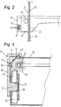
- Fig. 1 shows a perspective view of a cut-open body 1 of a refrigerator according to a first embodiment of the invention. To see are a bottom 2 and each of the lower half of side walls 3, 4 and a rear wall 5 of the body 1. The ceiling of the body 1 is not shown, as well as a door which is hinged in a conventional manner to the body 1 to its open front to close.
- a single height-adjustabledegutabsteller 7 is shown, but it is understood that a plurality ofdegutabsteller 7 can be provided one above the other.
- Thedegutabsteller 7 is supported by two carrier profiles 8, of which in Fig. 1 only one is visible and the mirror image opposite one another in each case at an edge of the inner space 6 between the rear wall 5 and the side walls 3 and 4 are arranged.
- the carrier profile 8 comprises a tooth profile 9, which fills the edge of the housing, with an elongated plane surface 10 which forms an angle of approximately 135 ° to the two adjacent walls 1 of the body, and a plurality of recessed into the plane surface 10th Recesses 11.
- a vertical rib 12 is formed on a leg of the carrier profile 8 extending along the side wall 3.
- the ratchet mechanism is directionally adjustable in a manner known per se, so that optionally, for example, a rotation of the pivot arm 16 drives an upward movement of the refrigerated goods carrier 7 and rotation of the pivot arm 16 keeps the refrigerated goods carrier 7 stationary, or the rotation in the counterclockwise direction keeps the refrigerated goods carrier 7 stationary, while the counterclockwise rotation drives a downward movement of the refrigerated goods carrier.
- the length of the pivot arm 16 is dimensioned so that its front tip in each position he can take over the front edge of the glass plate 15 protrudes, but without - at least in a widely deflected to the side position as in Fig. 1 presented - to impede the closing of the door.
- the pivoting arm 16 can be guided in a horizontal rail for stabilization in the vicinity of the front edge of the glass plate 15, for example in a slot of a (in the Fig. 1 not shown), the front tips of the arms 14 interconnecting web.
- Fig. 2 shows a side view of thedegutabstellers 7 according to a first embodiment of the embodiment of Fig. 1 ,
- a vertical hatched bar in Fig. 2 In a window 17 of one of the flat surface 10 facing inclined wall 18 of the housing 13 is one of the aforementioned two screws, here designated 19, to see whose turns 20 in the recesses 11 engage the tooth profile.
- the two carrier profiles 8 are able to absorb the weight of the refrigerated goods store 7 due to the engagement of the screws 19, the refrigerated goods stopper 7 is supported far away from its center of gravity, so that the resulting torque has to be absorbed. In the simplest case, this could serve a projection of the housing 13, which rests on one of the flat surface 10 facing side 21 of the rib 12 above the screw 19.
- a second roller 23 is disposed below the first roller 22 on the housing 13, which presses on the side 21 opposite side 24 of the rib 12.
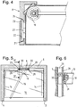
- FIG. 3 An in Fig. 3 illustrated by a horizontal section through the housing 13 training works mechanically as well as that of Fig. 2 , As with this are offset rollers 22, 23 on opposite sides 21, 24 of the rib 12 at.
- the difference to Fig. 2 is that the rollers 22, 23, instead of being mounted on the outside of the housing 13 cantilevered, housed inside the housing 13 with two-sided fixed axes, and that the rib 12 engages by a vertical slot housing between the rollers 23, 24.
- Two intermeshing bevel gears 31 connect the worm 19 with the ratchet mechanism arranged centrally in the housing 13.
- the support section 8 is constructed in two parts, with a simple and inexpensive extruded base profile 25 of constant cross-section and made separately from the base profile 25 and inserted into grooves 26 of this tooth profile. 9
- Fig. 4 shows an alternative development of the embodiment of Fig. 1 , in which mutually offset from each other rollers 22, 23 ofmégutabstellers 7 abut on opposite sides 21, 24 of a groove 27 of the support section 8.
- a vertical guide rail is here formed by two ribs 28 widening the tooth profile 9 and, between these and the rear wall 5, limited grooves 29 each open to the side. In these grooves 29 engage from side walls of the housing 13 supported rollers 30 a. Inside the housing 13 hidden rollers 31 are - as in the vertical section of Fig. 6 shown offset in height to the rollers 30 - on a front side of the ribs 28 at. Thus, the pairs of rollers 30, 31 compensate for the torque ofharigutabstellers 7, and the screw 19 is rotatable friction.
- FIG. 7 An in Fig. 7
- the third embodiment shown differs from that of the Flg. 1 essentially only by the ratchet mechanism and the pivot lever driving it. While in Fig. 1 the pivot lever between two stops is continuously movable and either runs empty on this entire movement depending on the direction or drives an adjustment of the refrigerated goods in a constant direction, the pivot lever 16 according to the third embodiment has a rest position in which it is perpendicular to the front of the housing 13th protrudes, and from which it is deflected against a return spring to the left or right, for example, to the in Fig. 7 shown stop position.
Description
Die vorliegende Erfindung betrifft ein Kältegerät, insbesondere ein Haushaltskältegerät, mit einem Gehäuse und einem in dem Gehäuse höhenverstellbaren Kühlgutabsteller.
Auf dem Markt verbreitet sind Kältegeräte mit an den Seitenwänden des Innenraums in verschiedenen Höhen angebrachten horizontalen Führungsnuten, in die Kühlgutabsteller einführbar sind. Mit einer solchen Konstruktion kann die Höhe der von den Abstellern begrenzten Fächer jeweils nur in dem Abstand der Nuten voneinander entsprechenden diskreten Schritten variiert werden. Die Höhenverstellung ist mühsam und zeitraubend, da ein zu versetzender Absteller vor dem Herausziehen entladen und nach dem Neuplatzieren wieder beladen werden muss.
Um ein bequemes Höhenverstellen eines Kühlgutabstellers ohne vorheriges Entladen zu ermöglichen, wurde das in der deutschen Patentanmeldung
Die vier Drehkörper dieses Kühlgutabstellers müssen untereinander gekoppelt sein, um sicherzustellen, dass alle vier Ecken des Kühlgutabstellers in gleicher Weise verschoben werden, und ein Verkanten des Kühlgutabstellers auszuschließen. Der für eine solche Kopplung benötigte Einbauraum steht für die Unterbringung von Kühlgut nicht mehr zur Verfügung. Um die Höhenverstellung zu realisieren, wird eine große Zahl von verschiedenen Bauteilen benötigt, deren Fertigung und Zusammenbau die Fertigungskosten des Kältegeräts erhöhen.
On the market widespread refrigeration devices are mounted on the side walls of the interior at different heights horizontal guide grooves in the refrigerated goods are insertable. With such a construction, the height of the trays delimited by the shelves can be varied only in discrete steps corresponding to the distance of the grooves from each other. The height adjustment is tedious and time-consuming, since a staggering stowage unloaded before pulling out and must be loaded again after Neuplatzieren.
In order to allow a comfortable Höhenverstellen a Kühlgutabstellers without prior unloading, which was in the German patent application
The four rotating bodies of this Kühlgutabstellers must be coupled together to ensure that all four corners of the Kühlgutabstellers be moved in the same way, and to exclude tilting of Kühlgutabstellers. The installation space required for such a coupling is no longer available for the storage of refrigerated goods. In order to realize the height adjustment, a large number of different components is needed whose production and assembly increase the manufacturing costs of the refrigeration device.
Aufgabe der vorliegenden Erfindung ist, ein Kältegerät mit einem stufenlos höhenverstellbaren Kühlgutabsteller zu schaffen, bei dem der Platzbedarf und die Komplexität eines Antriebsmechanismus für die Höhenverstellung verringert sind.Object of the present invention is to provide a refrigeration device with a continuously height-adjustable Kühlgutabsteller, in which the space required and the complexity of a drive mechanism for the height adjustment are reduced.
Die Aufgabe wird gelöst, indem bei einem Kältegerät mit einem Gehäuse und einem in dem Gehäuse höhenverstellbaren Kühlgutabsteller, bei dem wenigstens eine drehantreibbare Schnecke des Kühlgutabstellers mit wenigstens einem gehäusefesten Zahnprofil kämmt, der Kühlgutabsteller über insgesamt zwei Schnecken an dem Gehäuse derart abgestützt ist, dass seine Abstellfläche zumindest annähernd horizontal angeordnet ist.The object is achieved by supporting in a refrigerator with a housing and a height adjustable in the housing Kühlgutabsteller, wherein at least one rotatably driven screw of Kühlgutabstellers with at least one housing tooth profile, the Kühlgutabsteller is supported on a total of two screws on the housing such that its Abstellfläche is arranged at least approximately horizontally.
Die Schnecken können am Kühlgutabsteller so platziert sein, dass eine durch die Achsen der Schnecken verlaufende vertikale Ebene den Schwerpunkt des Kühlgutträgers enthält. Um eine gegen diese Ebene versetzte Anordnung des Schwerpunkts stabil zu halten, ist der Kühlgutträger vorzugsweise in wenigstens einer gehäusefesten Führungsschiene vertikal verstellbar gehalten.The screws can be placed on the refrigerated goods stand so that a vertical plane running through the axes of the screws contains the center of gravity of the refrigerated goods carrier. In order to keep a staggered against this plane arrangement of the center of gravity stable, the refrigerated goods is preferably held vertically adjustable in at least one housing-fixed guide rail.
Die Führungsschiene kann die Führungsfunktion einer oder mehrerer der Schnecken des in
Vorzugsweise sind diese zwei Zahnprofile benachbart zu einer gleichen Kante des Kühlgutabstellers angeordnet. Zwar tritt an dem Kühlgutabsteller, wenn dieser vertikal lediglich durch die zwei Zahnprofile abgestützt ist, bedingt durch sein Eigengewicht und das Gewicht von eventuell darauf deponiertem Kühlgut ein beträchtliches Drehmoment auf, doch kann dieses Drehmoment mit Hilfe der Führungsschiene abgefangen werden, so dass der Kühlgutabsteller dennoch stabil gehalten ist.Preferably, these two tooth profiles are arranged adjacent to a same edge of Kühlgutabstellers. Although occurs at the Kühlgutabsteller, if this is supported vertically only by the two tooth profiles, due to its own weight and the weight of possibly deposited thereon refrigerated considerable torque, but this torque can be intercepted by means of the guide rail, so that the Kühlgutabsteller nonetheless is held stable.
Die Anbringung der zwei Zahnprofile benachbart zu einer gleichen Kante des Kühlgutabstellers ermöglicht es, ein Getriebegehäuse für ein die Schnecken aneinander koppelndes Getriebe in einem Gehäuse unterzubringen, das sich Platz sparend allein entlang dieser Kante erstreckt.The attachment of the two tooth profiles adjacent to a same edge of the Kühlgutabstellers makes it possible to accommodate a gear housing for a snail coupling together gear in a housing that extends to save space alone along this edge.
Sowohl unter statischen Gesichtspunkten als auch im Hinblick auf die Nutzbarkeit des Innenraums des Gehäuses ist die besagte Kante zweckmäßigerweise die hintere Kante des Kühlgutabstellers.Both from a static point of view as well as with regard to the usability of the interior of the housing said edge is expediently the rear edge of the Kühlgutabstellers.
Um die Schnecken antreiben zu können, erstreckt sich ein Schwenkarm unter einer Platte des Kühlgutabstellers her bis zu deren vorderer Kante, wo er für einen Benutzer gut zugänglich ist.
Der Schwenkarm ist an die Schnecken vorzugsweise über einen Ratschenmechanismus gekoppelt, so dass durch mehrere Hin- und Herbewegungen des Schwenkarms der Kühlgutabsteller über eine große Entfernung in eine einzige, wählbare Richtung verstellt werden kann.
Dieser Ratschenmechanismus kann richtungsverstellbar sein; dann kann die gesamte Bewegungsfreiheit des Schwenkarms ausgenutzt werden, um eine Höhenverstellung in eine einzige Richtung anzutreiben.
Alternativ kann der Schwenkarm aus einer Ruhestellung heraus in entgegengesetzte Richtungen auslenkbar sein, wobei die Bewegung des Schwenkarms auf einer ersten Seite der Ruhestellung eine Aufwärtsbewegung des Kühlgutträgers und die Bewegung des Schwenkarms auf einer entgegengesetzten, zweiten Seite der Ruhestellung eine Abwärtsbewegung des Kühlgutträgers antreibt.
Die zwei Zahnprofile sind vorzugsweise Platz sparend in Kanten des Innenraums, zwischen Rückwand und Seitenwänden des Gehäuses, eingefügt.
Anstelle von in den Innenraum hinein ragenden Vorsprüngen kann ein solches Zahnprofil zweckmäßigerweise jeweils eine Windung der Schnecke aufnehmende Aussparungen in einer dem Kühlgutabsteller zugewandten ebenen Außenfläche haben.
Um den Kühlgutträger zu stabilisieren und insbesondere, um ein auf ihn wirkendes Drehmoment aufzufangen, und um gleichzeitig die bei der Höhenverstellung zu überwindende Reibung gering zu halten, weist die Führungsschiene wenigstens eine dem Zahnprofil entgegengesetzte Oberfläche auf, an der wenigstens eine Rolle des Kühlgutträgers anliegt. Die Rolle ermöglicht die Übertragung einer beträchtlichen Kraft in horizontaler Richtung, zur Kompensierung des Drehmoments, ohne dass durch übermäßige Reibung zwischen Kühlgutträger und Führungsschiene die Höhenverstellung des Kühlgutträgers blockiert wird.In order to be able to drive the screws, a swivel arm extends beneath a plate of the refrigerated goods store up to its front edge, where it is easily accessible to a user.
The pivoting arm is preferably coupled to the screws via a ratchet mechanism, so that by several reciprocating movements of the pivoting arm of Kühlgutabsteller can be adjusted over a long distance in a single, selectable direction.
This ratchet mechanism can be directionally adjustable; then the entire freedom of movement of the pivot arm can be exploited to drive a height adjustment in a single direction.
Alternatively, the pivot arm can be deflected out of a rest position in opposite directions, wherein the movement of the pivot arm on a first side of the rest position an upward movement of the refrigerated goods and the movement of the pivot arm on an opposite, second side of the rest position drives a downward movement of the refrigerated goods.
The two tooth profiles are preferably space-saving in edges of the interior, inserted between the rear wall and side walls of the housing.
Instead of projecting into the interior projections such a tooth profile expediently each have a turn of the worm receiving recesses in the Kühlgutabsteller facing flat outer surface.
In order to stabilize the refrigerated goods and in particular to absorb a torque acting on it, and at the same time to minimize the height adjustment to be overcome friction, the guide rail has at least one tooth profile opposite surface on which rests at least one roll of Kühlgutträgers. The roller allows the transmission of a considerable force in the horizontal direction, to compensate for the torque, without the height adjustment of the refrigerated goods is blocked by excessive friction between refrigerated goods and guide rail.
Besonders bevorzugt ist, wenn die Führungsschiene zwei einander entgegengesetzte Oberflächen aufweist, an denen jeweils wenigstens eine Rolle des Kühlgutträgers anliegt. Dies ermöglicht eine weitgehend spielfreie, reibungsarme Führung des Kühlgutträgers.It is particularly preferred if the guide rail has two mutually opposite surfaces against which at least one roller of the refrigerated goods carrier rests in each case. This allows a largely backlash-free, low-friction guidance of the refrigerated goods carrier.
Wenn darüber hinaus die an verschiedenen Oberflächen der Führungsschiene anliegenden Rollen zueinander höhenversetzt sind, ermöglichen die Rollen darüber hinaus die Entlastung der Schnecken und Führungsschienen von horizontalen Kräften und damit eine Reduzierung der bei der Höhenverstellung auftretenden Reibung.In addition, when the rollers resting against different surfaces of the guide rail are offset in height relative to one another, the rollers furthermore make it possible to relieve the screws and guide rails of horizontal forces and thus to reduce the friction occurring during the height adjustment.
Vorzugsweise ist die Führungsschiene eine Rippe oder eine Nut, die sich an einer Seitenwand des Gehäuses erstreckt. Die einander gegenüberliegenden Oberflächen der Führungsschiene sind dann zweckmäßigerweise Seitenflächen der Rippe oder der Nut.Preferably, the guide rail is a rib or groove extending on a side wall of the housing. The opposing surfaces of the guide rail are then expediently side surfaces of the rib or the groove.
Ein Trägerprofil, das die Führungsschiene und das Zahnprofil aufweist, kann zweckmäßigerweise an einer Kante zwischen Rückwand und einer Seitenwand des Gehäuses montiert sein. So können horizontale Kräfte, die zwischen dem Kühlgutabsteller einerseits und der Führungsschiene oder deren Zahnprofil andererseits wirken, in dem Trägerprofil aufgefangen und kompensiert werden, so dass an die Tragfähigkeit der Wände des Gehäuses keine erhöhten Anforderungen gestellt werden müssen.A carrier profile having the guide rail and the tooth profile may conveniently be mounted on an edge between the rear wall and a side wall of the housing. Thus, horizontal forces acting between the refrigerated goods on the one hand and the guide rail or the tooth profile on the other hand, be absorbed and compensated in the carrier profile, so that no increased demands on the carrying capacity of the walls of the housing.
Weitere Merkmale und Vorteile der Erfindung ergeben sich aus der nachfolgenden Beschreibung von Ausführungsbeispielen unter Bezugnahme auf die beigefügten Figuren. Es zeigen:
- Fig. 1
- eine perspektivische, teilweise aufgeschnittene Ansicht eines Kältegerätekorpus mit einem höhenverstellbaren Kühlgutabsteller gemäß der Erfindung;
- Fig. 2
- eine partielle Seitenansicht des Kühlgutabstellers gemäß einer ersten Weiterbildung der Erfindung;
- Fig. 3
- einen horizontalen Teilschnitt durch das Getriebegehäuse und ein Trägerprofil gemäß einer zweiten Weiterbildung;
- Fig. 4
- einen zu
Fig. 3 analogen Schnitt gemäß einer dritten Weiterbildung; - Fig. 5
- einen horizontalen Schnitt durch ein Kältegerät gemäß einer zweiten Ausgestaltung der Erfindung;
- Fig. 6
- einen Schnitt entlang der in
Fig. 5 mit VI-VI bezeichneten Ebene; - Fig. 7
- eine zu
Fig. 1 analoge Ansicht gemäß einer dritten Ausgestaltung; und - Fig. 8
- ein vergrößertes Detail der dritten Ausgestaltung im Schnitt.
- Fig. 1
- a perspective, partially cutaway view of a refrigerator body with a height-adjustable Kühlgutabsteller according to the invention;
- Fig. 2
- a partial side view of Kühlgutabstellers according to a first embodiment of the invention;
- Fig. 3
- a horizontal partial section through the gear housing and a carrier profile according to a second embodiment;
- Fig. 4
- one too
Fig. 3 analog section according to a third development; - Fig. 5
- a horizontal section through a refrigerator according to a second embodiment of the invention;
- Fig. 6
- a cut along in
Fig. 5 level designated VI-VI; - Fig. 7
- one too
Fig. 1 analogous view according to a third embodiment; and - Fig. 8
- an enlarged detail of the third embodiment in section.
Im Innenraum 6 des Korpus 1 ist ein einziger höhenverstellbarer Kühlgutabsteller 7 gezeigt, doch versteht sich, dass mehrere Kühlgutabsteller 7 übereinander vorgesehen sein können. Der Kühlgutabsteller 7 ist unterstützt von zwei Trägerprofilen 8, von denen in
In die Aussparungen 11 der zwei Trägerprofile 8 eingreifende, jeweils in eine vertikale Achse gekoppelt drehbare Schnecken sind - in
Ein Schwenkarm 16, der die Schnecken über einen in dem Gehäuse 13 untergebrachten, Ratschenmechanismus antreibt, erstreckt sich unter der Glasplatte 15 her nach vorn. Der Ratschenmechanismus ist in an sich bekannter Weise richtungsverstellbar, so dass wahlweise z.B. eine Drehung des Schwenkarms 16 im Uhrzeigersinn eine Aufwärtsbewegung des Kühlgutträgers 7 antreibt und eine Drehung des Schwenkarms 16 den Kühlgutträger 7 unbewegt lässt, oder die Drehung im Gegenuhrzeigersinn den Kühlgutträger 7 unbewegt lässt, während die Drehung im Gegenuhrzeigersinn eine Abwärtsbewegung des Kühlgutträgers antreibt. Die Länge des Schwenkarms 16 ist so bemessen, dass seine vordere Spitze in jeder Stellung, die er einnehmen kann, über den vorderen Rand der Glasplatte 15 übersteht, ohne jedoch - zumindest in einer weit zur Seite ausgelenkten Stellung wie der in
Indem der Vorsprung und die Schnecke 19 jeweils entgegengesetzt orientierte horizontale Kräfte auf die Rippe 12 bzw. das Zahnprofil 9 übertragen, kann das Drehmoment kompensiert werden, allerdings mit dem Preis einer erheblichen Reibung zwischen den gegeneinander bewegten Oberflächen des Vorsprungs und der Rippe 12 bzw. von Schnecke 19 und Zahnprofil 9.By the projection and the
Auf Seiten der Rippe 12 kann diese Reibung weitgehend vermieden werden, indem, wie in
Um auch die Schnecke 19 und das Zahnprofil 9 von übermäßiger Reibung zu entlasten, ist einer zweckmäßigen Weiterbildung zufolge eine zweite Rolle 23 unterhalb der ersten Rolle 22 am Gehäuse 13 angeordnet, die zu der Seite 21 entgegengesetzte Seite 24 der Rippe 12 drückt.In order to relieve the
Eine in
Zwei ineinander greifende Kegelräder 31 verbinden die Schnecke 19 mit dem zentral im Gehäuse 13 angeordneten Ratschenmechanismus.Two intermeshing
Wie in
Eine zweite Ausgestaltung, die ein einziges, zentral an der Rückwand 5 des Korpus 1 angebrachtes Trägerprofil 8 verwendet, ist in
Eine vertikale Führungsschiene ist hier durch zwei das Zahnprofil 9 verbreiternde Rippen 28 und zwischen diesen und der Rückwand 5 begrenzte, jeweils zur Seite hin offene Nuten 29 gebildet. In diese Nuten 29 greifen von Seitenwänden des Gehäuses 13 getragene Rollen 30 ein. Im Inneren des Gehäuses 13 verborgene Rollen 31 liegen - wie in dem vertikalen Schnitt der
Eine in
Um in der Ruhestellung die Tür des Kältegeräts schließen zu können, andererseits aber auch in der Anschlagstellung die Spitze des Schwenkhebels 16 noch gut greifen zu können, ist dieser längensverstellbar, und zwar, wie sich aus dem in
Claims (14)
- Refrigeration appliance, in particular a household refrigeration appliance, having a housing (1) and a shelf for refrigerated goods (7), the height of which can be adjusted in the housing (1), wherein at least one rotatably drivable screw (19) of the shelf for refrigerated goods (7) engages with at least one toothed profile (9) that is fixed to the housing, wherein the shelf for refrigerated goods (7) is supported by way of a total of two screws (19) on the housing (1) in such a manner that its storage surface is held at least approximately horizontal, characterised in that a pivot arm (16) for driving the screws (19) extends below a plate (15) of the shelf for refrigerated goods (7) up to its front edge, and that the guide (12; 27; 28, 29) has a surface (21) opposite the toothed profile (9), on which at least one roller (22) of the support for refrigerated goods (7) rests.
- Refrigeration appliance according to claim 1, characterised in that at least one guide (12; 27; 28, 29) fixed to the housing is used to support the shelf for refrigerated goods (7), allowing it to be held in a vertically adjustable manner with an at least approximately horizontal storage surface.
- Refrigeration appliance according to one of claims 1 or 2, characterised in that the maximum number of toothed profiles (9) is 2.
- Refrigeration appliance according to claim 3, characterised in that the two toothed profiles (9) are disposed adjacent to an identical edge of the shelf for refrigerated goods (7).
- Refrigeration appliance according to claim 4, characterised in that a transmission housing (13) extends along the edge of the shelf for refrigerated goods (7) between screws (19) engaging with the toothed profiles (9).
- Refrigeration appliance according to claim 4 or 5, characterised in that the edge is the rear edge of the shelf for refrigerated goods (7).
- Refrigeration appliance according to one of the preceding claims, characterised in that the pivot arm (16) is coupled to the screws (19) by way of a directionally adjustable ratchet mechanism.
- Refrigeration appliance according to one of claims 1 to 7, characterised in that the two toothed profiles (9) are introduced into edges between the rear wall (5) and side walls (3, 4) of the housing (1).
- Refrigeration appliance according to claim 8, characterised in that the toothed profiles (9) have a flat outer surface (10) facing the shelf for refrigerated goods (7), in which cutouts (11) each receiving a turn (20) of the screw (19) are formed.
- Refrigeration appliance according to one of claims 2 to 9, characterised in that the guide (12; 27; 28) has two mutually opposing surfaces (21, 24), on which at least one roller (22, 23; 30, 31) of the support for refrigerated goods (7) rests in each instance.
- Refrigeration appliance according to claim 10, characterised in that the rollers (22, 23; 30, 31) resting on different surfaces (21, 24) of the guide rail (12; 27; 28) have a height offset in respect of one another.
- Refrigeration appliance according to claim 10 or 11, characterised in that the guide rail is a rib (12) or groove (27), which extends along a side wall (3, 4) of the housing (1).
- Refrigeration appliance according to claim 12, characterised in that the mutually opposing surfaces (21; 24) of the guide rail are side faces of the rib (12) or groove (27).
- Refrigeration appliance according to one of claims 2 to 13, characterised in that a support profile (8), which has the guide rail (12, 27) and the toothed profile (9) is fitted on an edge between the rear wall (5) and a side wall (3, 4) of the housing.
Priority Applications (1)
| Application Number | Priority Date | Filing Date | Title |
|---|---|---|---|
| PL10702648T PL2396613T3 (en) | 2009-02-13 | 2010-01-27 | Refrigerator with height-adjustable shelf for refrigerated goods |
Applications Claiming Priority (2)
| Application Number | Priority Date | Filing Date | Title |
|---|---|---|---|
| DE102009000845A DE102009000845A1 (en) | 2009-02-13 | 2009-02-13 | Refrigeration unit with height-adjustable refrigerated goods storage |
| PCT/EP2010/050930 WO2010091955A2 (en) | 2009-02-13 | 2010-01-27 | Refrigerator with height-adjustable shelf for refrigerated goods |
Publications (2)
| Publication Number | Publication Date |
|---|---|
| EP2396613A2 EP2396613A2 (en) | 2011-12-21 |
| EP2396613B1 true EP2396613B1 (en) | 2018-10-17 |
Family
ID=42338419
Family Applications (1)
| Application Number | Title | Priority Date | Filing Date |
|---|---|---|---|
| EP10702648.6A Active EP2396613B1 (en) | 2009-02-13 | 2010-01-27 | Refrigerator with height-adjustable shelf for refrigerated goods |
Country Status (6)
| Country | Link |
|---|---|
| US (1) | US8529001B2 (en) |
| EP (1) | EP2396613B1 (en) |
| CN (1) | CN102301195B (en) |
| DE (1) | DE102009000845A1 (en) |
| PL (1) | PL2396613T3 (en) |
| WO (1) | WO2010091955A2 (en) |
Families Citing this family (25)
| Publication number | Priority date | Publication date | Assignee | Title |
|---|---|---|---|---|
| EP2489967B1 (en) * | 2011-02-18 | 2019-08-28 | Electrolux Home Products Corporation N.V. | Refrigerating appliance |
| US8960825B2 (en) * | 2011-10-04 | 2015-02-24 | Lg Electronics Inc. | Refrigerator |
| US8702049B2 (en) * | 2012-09-10 | 2014-04-22 | Benedict Vieira | Ergonomic space-saving customizable workstation |
| CN103512309B (en) * | 2012-11-21 | 2015-12-16 | 北京中家智铭设计有限公司 | A kind of adjustable type refrigerator article-holding device |
| CN103148670A (en) * | 2013-03-20 | 2013-06-12 | 浙江腾云制冷科技有限公司 | Space-saving tea leaf cold-storage cabinet |
| CN104291035B (en) * | 2014-09-23 | 2017-03-15 | 浙江双友物流器械股份有限公司 | A kind of decker in compartment |
| AU2014410494B2 (en) * | 2014-11-03 | 2018-08-30 | Arcelik Anonim Sirketi | Improved shelf assembly and refrigeration appliance having the same |
| CN106276007A (en) * | 2015-06-23 | 2017-01-04 | 辽宁聚龙海目星智能物流科技有限公司 | A kind of Intelligent logistics cabinet of lift grid variable volume |
| MX2019004678A (en) * | 2016-10-18 | 2019-11-25 | Walmart Apollo Llc | Shelving system having stowable shelves. |
| US10314393B2 (en) | 2017-03-07 | 2019-06-11 | Haier Us Appliance Solutions, Inc. | Refrigerator appliance and variable shelf assembly |
| US10161671B2 (en) | 2017-04-21 | 2018-12-25 | Haier Us Appliance Solutions, Inc. | Adjustable shelf for a refrigerator appliance |
| CN107166862B (en) * | 2017-06-29 | 2020-07-28 | 海信容声(广东)冰箱有限公司 | Adjustable shelf structure for refrigerator and refrigerator |
| US11627212B2 (en) | 2017-10-03 | 2023-04-11 | Hatchmed Corporation | Clamp to attach electronic device holder to bed rail |
| US10601971B2 (en) | 2017-10-03 | 2020-03-24 | Hatchmed Corporation | Portable electronic device holder with assistance request button and method powering portable electronic device |
| US11895256B2 (en) | 2017-10-03 | 2024-02-06 | Hatchmed Corporation | Hall monitor for a health care facility |
| US10451336B2 (en) | 2017-10-12 | 2019-10-22 | Whirlpool Corporation | Adjustable refrigerator compartment and door assembly |
| US10561233B1 (en) * | 2018-12-14 | 2020-02-18 | Hi-Max Innovation Co., Ltd. | Workstation with pneumatic height adjustable desk |
| US10683961B1 (en) * | 2019-07-05 | 2020-06-16 | Cass Hudson Co., Inc. | Platform assembly |
| KR20210032812A (en) * | 2019-09-17 | 2021-03-25 | 엘지전자 주식회사 | Refrigerator |
| CN111174524B (en) * | 2020-01-20 | 2021-08-31 | 合肥华凌股份有限公司 | Shelf assembly and storage cabinet |
| CN111481001B (en) * | 2020-03-18 | 2022-04-05 | 合肥美的电冰箱有限公司 | Shelf device and storage cabinet |
| CN111765711B (en) * | 2020-07-02 | 2021-09-21 | 长虹美菱股份有限公司 | Refrigerator shelf and refrigerator applying same |
| US11727768B2 (en) | 2020-08-13 | 2023-08-15 | Hatchmed Corporation | Hall monitor for a health care facility |
| US11892229B2 (en) * | 2021-02-24 | 2024-02-06 | Whirlpool Corporation | Modular storage |
| US11713917B2 (en) * | 2021-06-18 | 2023-08-01 | Whirlpool Corporation | Refrigerator appliance with self-adjusting mullion |
Citations (1)
| Publication number | Priority date | Publication date | Assignee | Title |
|---|---|---|---|---|
| US20080203041A1 (en) * | 2007-02-26 | 2008-08-28 | Samsung Electronics Co., Ltd. | Variable shelf assembly and refrigerator having the same |
Family Cites Families (26)
| Publication number | Priority date | Publication date | Assignee | Title |
|---|---|---|---|---|
| US128775A (en) * | 1872-07-09 | Improvement in dentists and barbers chairs | ||
| US97489A (en) * | 1869-12-07 | Croft | ||
| US603148A (en) * | 1898-04-26 | meyrowitz | ||
| US104161A (en) * | 1870-06-14 | Improved school-furniture | ||
| US1556711A (en) * | 1924-03-17 | 1925-10-13 | Pietrzycki Ziegmund Peters | Shelf cabinet |
| US2841459A (en) * | 1957-03-26 | 1958-07-01 | Gen Motors Corp | Vertically adjustable refrigerator shelves |
| US2978113A (en) * | 1958-07-03 | 1961-04-04 | Jervis Corp | Tray elevation adjustment |
| US3188161A (en) * | 1962-12-28 | 1965-06-08 | Gen Motors Corp | Vertically adjustable shelf |
| US3885846A (en) * | 1973-12-05 | 1975-05-27 | Lieh Chuang | Adjusting apparatus for refrigerators supporting shelf |
| US3982801A (en) * | 1975-11-17 | 1976-09-28 | General Motors Corporation | Power-operating vertically adjustable cantilever shelves for appliance cabinets |
| US4217010A (en) * | 1978-12-22 | 1980-08-12 | General Electric Company | Adjustable volume-split refrigerator |
| DE3472152D1 (en) * | 1984-06-26 | 1988-07-21 | Tandberg Data | Stand for a video display unit adjustable in height |
| JPH03170780A (en) | 1989-11-29 | 1991-07-24 | Matsushita Refrig Co Ltd | Rack device for refrigerator |
| US5199778A (en) * | 1990-01-19 | 1993-04-06 | Matsushita Refrigeration Company | Shelf apparatus for a refrigerator |
| JP2752300B2 (en) | 1992-07-22 | 1998-05-18 | シャープ株式会社 | Refrigerator shelf device |
| GB2309163B (en) * | 1996-01-18 | 1999-06-30 | Okamura Corp | Table with a height adjustable side panel |
| US5913584A (en) * | 1997-09-23 | 1999-06-22 | White Consolidated Industries, Inc. | Adjustable refrigerator shelf |
| US6065821A (en) * | 1998-05-15 | 2000-05-23 | Maytag Corporation | Vertically adjustable shelf and support rail arrangement for use in a cabinet |
| FR2851751B1 (en) * | 2003-02-28 | 2006-06-23 | France Design | VEHICLE REAR BEARING SYSTEM |
| JP2004286411A (en) * | 2003-03-25 | 2004-10-14 | Mitsubishi Electric Corp | Refrigerator |
| KR20050028265A (en) * | 2003-09-18 | 2005-03-22 | 엘지전자 주식회사 | Device for lifting shelf for refrigerator |
| KR100833370B1 (en) * | 2006-11-20 | 2008-05-28 | 엘지전자 주식회사 | Elevation adjustment structure of shelf for refrigerator |
| KR100916699B1 (en) * | 2007-04-06 | 2009-09-11 | 엘지전자 주식회사 | Refrigerator |
| US8556093B2 (en) * | 2007-04-16 | 2013-10-15 | ADCO Industries—Technologies, L.P. | Supporting consumer products |
| DE102007029176A1 (en) | 2007-06-25 | 2009-01-08 | BSH Bosch und Siemens Hausgeräte GmbH | The refrigerator |
| WO2010054683A1 (en) * | 2008-11-11 | 2010-05-20 | BSH Bosch und Siemens Hausgeräte GmbH | Refrigeration device having adjustable-height refrigerated goods placement |
-
2009
- 2009-02-13 DE DE102009000845A patent/DE102009000845A1/en not_active Withdrawn
-
2010
- 2010-01-27 US US13/146,923 patent/US8529001B2/en not_active Expired - Fee Related
- 2010-01-27 PL PL10702648T patent/PL2396613T3/en unknown
- 2010-01-27 WO PCT/EP2010/050930 patent/WO2010091955A2/en active Application Filing
- 2010-01-27 CN CN201080005953.7A patent/CN102301195B/en not_active Expired - Fee Related
- 2010-01-27 EP EP10702648.6A patent/EP2396613B1/en active Active
Patent Citations (1)
| Publication number | Priority date | Publication date | Assignee | Title |
|---|---|---|---|---|
| US20080203041A1 (en) * | 2007-02-26 | 2008-08-28 | Samsung Electronics Co., Ltd. | Variable shelf assembly and refrigerator having the same |
Also Published As
| Publication number | Publication date |
|---|---|
| PL2396613T3 (en) | 2019-04-30 |
| WO2010091955A2 (en) | 2010-08-19 |
| CN102301195B (en) | 2014-12-10 |
| CN102301195A (en) | 2011-12-28 |
| EP2396613A2 (en) | 2011-12-21 |
| US20110290807A1 (en) | 2011-12-01 |
| US8529001B2 (en) | 2013-09-10 |
| DE102009000845A1 (en) | 2010-08-19 |
| WO2010091955A3 (en) | 2010-11-11 |
Similar Documents
| Publication | Publication Date | Title |
|---|---|---|
| EP2396613B1 (en) | Refrigerator with height-adjustable shelf for refrigerated goods | |
| EP2424421B1 (en) | Apparatus for adjusting the height of a counter which is guided in a household device by way of at least one pull-out guide | |
| EP1743128B1 (en) | Domestic appliance having a swiveled display screen | |
| EP2347203B1 (en) | Refrigeration device having adjustable-height refrigerated goods placement | |
| EP2513398A1 (en) | Running gear arrangement having a guide rail for a sliding door | |
| DE3942584A1 (en) | SLIDE-FOLDING DOOR SYSTEM FOR A CABINET | |
| EP2395876B1 (en) | Refrigerator with height-adjustable shelf for refrigerated goods | |
| WO2016173894A1 (en) | Fitting for a corner cupboard, and corner cupboard with fitting | |
| WO2006120137A1 (en) | Refrigerating device with height-adjustable carrier for refrigerated goods | |
| EP1637053A1 (en) | Table, in particular a working table | |
| EP3676505A1 (en) | Drawer pull-out guide | |
| EP0875175B1 (en) | Rubbish collector for incorporation in a cupboard | |
| EP2394117B1 (en) | Refrigeration appliance having a vertically adjustable tray for refrigerated goods | |
| EP0788767B1 (en) | X-ray diagnostic apparatus | |
| EP1581772A1 (en) | Domestic appliance, especially a high fitment device comprising a wall mounting device | |
| EP2394116B1 (en) | Refrigerator with height-adjustable shelf for refrigerated goods | |
| EP3429431A1 (en) | Convertible multifunctional furniture | |
| EP3750518A1 (en) | Bathtub hoist | |
| EP0625322B1 (en) | Bed | |
| DE102004020267A1 (en) | An indicator screen for a domestic appliance has a hinge system to allow pull-out and angular turning of the screen from the housing | |
| DE102011081582A1 (en) | Rail extension device for domestic appliance i.e. oven, utilized for preparing food product, has support system that is spaced apart from pivot axes, where support system is connected with locking lever for guidance of pivotal movement | |
| DE2914374C2 (en) | Device for adjusting a swiveling bed frame part | |
| DE1808996C3 (en) | Device for the height-adjustable arrangement of a pull-out crockery basket in a dishwasher | |
| EP3754147A1 (en) | Lamellar lift system and container furniture comprising such a lamellar lift system | |
| EP2058255B1 (en) | Device for shaking a good in the form of sheet layers |
Legal Events
| Date | Code | Title | Description |
|---|---|---|---|
| PUAI | Public reference made under article 153(3) epc to a published international application that has entered the european phase |
Free format text: ORIGINAL CODE: 0009012 |
|
| 17P | Request for examination filed |
Effective date: 20110913 |
|
| AK | Designated contracting states |
Kind code of ref document: A2 Designated state(s): AT BE BG CH CY CZ DE DK EE ES FI FR GB GR HR HU IE IS IT LI LT LU LV MC MK MT NL NO PL PT RO SE SI SK SM TR |
|
| RIN1 | Information on inventor provided before grant (corrected) |
Inventor name: PFISTER, BERND Inventor name: CALVILLO, JUAN ANTONIO Inventor name: FINK, JUERGEN |
|
| DAX | Request for extension of the european patent (deleted) | ||
| RAP1 | Party data changed (applicant data changed or rights of an application transferred) |
Owner name: BSH HAUSGERAETE GMBH |
|
| STAA | Information on the status of an ep patent application or granted ep patent |
Free format text: STATUS: EXAMINATION IS IN PROGRESS |
|
| 17Q | First examination report despatched |
Effective date: 20170111 |
|
| GRAP | Despatch of communication of intention to grant a patent |
Free format text: ORIGINAL CODE: EPIDOSNIGR1 |
|
| STAA | Information on the status of an ep patent application or granted ep patent |
Free format text: STATUS: GRANT OF PATENT IS INTENDED |
|
| INTG | Intention to grant announced |
Effective date: 20180615 |
|
| GRAS | Grant fee paid |
Free format text: ORIGINAL CODE: EPIDOSNIGR3 |
|
| GRAA | (expected) grant |
Free format text: ORIGINAL CODE: 0009210 |
|
| STAA | Information on the status of an ep patent application or granted ep patent |
Free format text: STATUS: THE PATENT HAS BEEN GRANTED |
|
| AK | Designated contracting states |
Kind code of ref document: B1 Designated state(s): AT BE BG CH CY CZ DE DK EE ES FI FR GB GR HR HU IE IS IT LI LT LU LV MC MK MT NL NO PL PT RO SE SI SK SM TR |
|
| REG | Reference to a national code |
Ref country code: GB Ref legal event code: FG4D Free format text: NOT ENGLISH |
|
| REG | Reference to a national code |
Ref country code: CH Ref legal event code: EP |
|
| REG | Reference to a national code |
Ref country code: IE Ref legal event code: FG4D Free format text: LANGUAGE OF EP DOCUMENT: GERMAN |
|
| REG | Reference to a national code |
Ref country code: DE Ref legal event code: R096 Ref document number: 502010015463 Country of ref document: DE Ref country code: AT Ref legal event code: REF Ref document number: 1054550 Country of ref document: AT Kind code of ref document: T Effective date: 20181115 |
|
| REG | Reference to a national code |
Ref country code: NL Ref legal event code: MP Effective date: 20181017 |
|
| REG | Reference to a national code |
Ref country code: LT Ref legal event code: MG4D |
|
| PG25 | Lapsed in a contracting state [announced via postgrant information from national office to epo] |
Ref country code: NL Free format text: LAPSE BECAUSE OF FAILURE TO SUBMIT A TRANSLATION OF THE DESCRIPTION OR TO PAY THE FEE WITHIN THE PRESCRIBED TIME-LIMIT Effective date: 20181017 |
|
| PG25 | Lapsed in a contracting state [announced via postgrant information from national office to epo] |
Ref country code: LV Free format text: LAPSE BECAUSE OF FAILURE TO SUBMIT A TRANSLATION OF THE DESCRIPTION OR TO PAY THE FEE WITHIN THE PRESCRIBED TIME-LIMIT Effective date: 20181017 Ref country code: ES Free format text: LAPSE BECAUSE OF FAILURE TO SUBMIT A TRANSLATION OF THE DESCRIPTION OR TO PAY THE FEE WITHIN THE PRESCRIBED TIME-LIMIT Effective date: 20181017 Ref country code: HR Free format text: LAPSE BECAUSE OF FAILURE TO SUBMIT A TRANSLATION OF THE DESCRIPTION OR TO PAY THE FEE WITHIN THE PRESCRIBED TIME-LIMIT Effective date: 20181017 Ref country code: FI Free format text: LAPSE BECAUSE OF FAILURE TO SUBMIT A TRANSLATION OF THE DESCRIPTION OR TO PAY THE FEE WITHIN THE PRESCRIBED TIME-LIMIT Effective date: 20181017 Ref country code: BG Free format text: LAPSE BECAUSE OF FAILURE TO SUBMIT A TRANSLATION OF THE DESCRIPTION OR TO PAY THE FEE WITHIN THE PRESCRIBED TIME-LIMIT Effective date: 20190117 Ref country code: LT Free format text: LAPSE BECAUSE OF FAILURE TO SUBMIT A TRANSLATION OF THE DESCRIPTION OR TO PAY THE FEE WITHIN THE PRESCRIBED TIME-LIMIT Effective date: 20181017 Ref country code: NO Free format text: LAPSE BECAUSE OF FAILURE TO SUBMIT A TRANSLATION OF THE DESCRIPTION OR TO PAY THE FEE WITHIN THE PRESCRIBED TIME-LIMIT Effective date: 20190117 Ref country code: IS Free format text: LAPSE BECAUSE OF FAILURE TO SUBMIT A TRANSLATION OF THE DESCRIPTION OR TO PAY THE FEE WITHIN THE PRESCRIBED TIME-LIMIT Effective date: 20190217 |
|
| PG25 | Lapsed in a contracting state [announced via postgrant information from national office to epo] |
Ref country code: PT Free format text: LAPSE BECAUSE OF FAILURE TO SUBMIT A TRANSLATION OF THE DESCRIPTION OR TO PAY THE FEE WITHIN THE PRESCRIBED TIME-LIMIT Effective date: 20190217 Ref country code: SE Free format text: LAPSE BECAUSE OF FAILURE TO SUBMIT A TRANSLATION OF THE DESCRIPTION OR TO PAY THE FEE WITHIN THE PRESCRIBED TIME-LIMIT Effective date: 20181017 |
|
| REG | Reference to a national code |
Ref country code: DE Ref legal event code: R097 Ref document number: 502010015463 Country of ref document: DE |
|
| PG25 | Lapsed in a contracting state [announced via postgrant information from national office to epo] |
Ref country code: DK Free format text: LAPSE BECAUSE OF FAILURE TO SUBMIT A TRANSLATION OF THE DESCRIPTION OR TO PAY THE FEE WITHIN THE PRESCRIBED TIME-LIMIT Effective date: 20181017 Ref country code: IT Free format text: LAPSE BECAUSE OF FAILURE TO SUBMIT A TRANSLATION OF THE DESCRIPTION OR TO PAY THE FEE WITHIN THE PRESCRIBED TIME-LIMIT Effective date: 20181017 Ref country code: CZ Free format text: LAPSE BECAUSE OF FAILURE TO SUBMIT A TRANSLATION OF THE DESCRIPTION OR TO PAY THE FEE WITHIN THE PRESCRIBED TIME-LIMIT Effective date: 20181017 |
|
| PLBE | No opposition filed within time limit |
Free format text: ORIGINAL CODE: 0009261 |
|
| STAA | Information on the status of an ep patent application or granted ep patent |
Free format text: STATUS: NO OPPOSITION FILED WITHIN TIME LIMIT |
|
| PG25 | Lapsed in a contracting state [announced via postgrant information from national office to epo] |
Ref country code: MC Free format text: LAPSE BECAUSE OF FAILURE TO SUBMIT A TRANSLATION OF THE DESCRIPTION OR TO PAY THE FEE WITHIN THE PRESCRIBED TIME-LIMIT Effective date: 20181017 Ref country code: SK Free format text: LAPSE BECAUSE OF FAILURE TO SUBMIT A TRANSLATION OF THE DESCRIPTION OR TO PAY THE FEE WITHIN THE PRESCRIBED TIME-LIMIT Effective date: 20181017 Ref country code: EE Free format text: LAPSE BECAUSE OF FAILURE TO SUBMIT A TRANSLATION OF THE DESCRIPTION OR TO PAY THE FEE WITHIN THE PRESCRIBED TIME-LIMIT Effective date: 20181017 Ref country code: SM Free format text: LAPSE BECAUSE OF FAILURE TO SUBMIT A TRANSLATION OF THE DESCRIPTION OR TO PAY THE FEE WITHIN THE PRESCRIBED TIME-LIMIT Effective date: 20181017 Ref country code: RO Free format text: LAPSE BECAUSE OF FAILURE TO SUBMIT A TRANSLATION OF THE DESCRIPTION OR TO PAY THE FEE WITHIN THE PRESCRIBED TIME-LIMIT Effective date: 20181017 |
|
| REG | Reference to a national code |
Ref country code: CH Ref legal event code: PL |
|
| 26N | No opposition filed |
Effective date: 20190718 |
|
| GBPC | Gb: european patent ceased through non-payment of renewal fee |
Effective date: 20190127 |
|
| PG25 | Lapsed in a contracting state [announced via postgrant information from national office to epo] |
Ref country code: LU Free format text: LAPSE BECAUSE OF NON-PAYMENT OF DUE FEES Effective date: 20190127 |
|
| REG | Reference to a national code |
Ref country code: BE Ref legal event code: MM Effective date: 20190131 |
|
| REG | Reference to a national code |
Ref country code: IE Ref legal event code: MM4A |
|
| PG25 | Lapsed in a contracting state [announced via postgrant information from national office to epo] |
Ref country code: SI Free format text: LAPSE BECAUSE OF FAILURE TO SUBMIT A TRANSLATION OF THE DESCRIPTION OR TO PAY THE FEE WITHIN THE PRESCRIBED TIME-LIMIT Effective date: 20181017 Ref country code: FR Free format text: LAPSE BECAUSE OF NON-PAYMENT OF DUE FEES Effective date: 20190131 |
|
| PG25 | Lapsed in a contracting state [announced via postgrant information from national office to epo] |
Ref country code: BE Free format text: LAPSE BECAUSE OF NON-PAYMENT OF DUE FEES Effective date: 20190131 |
|
| PG25 | Lapsed in a contracting state [announced via postgrant information from national office to epo] |
Ref country code: CH Free format text: LAPSE BECAUSE OF NON-PAYMENT OF DUE FEES Effective date: 20190131 Ref country code: GB Free format text: LAPSE BECAUSE OF NON-PAYMENT OF DUE FEES Effective date: 20190127 Ref country code: LI Free format text: LAPSE BECAUSE OF NON-PAYMENT OF DUE FEES Effective date: 20190131 |
|
| PG25 | Lapsed in a contracting state [announced via postgrant information from national office to epo] |
Ref country code: IE Free format text: LAPSE BECAUSE OF NON-PAYMENT OF DUE FEES Effective date: 20190127 |
|
| REG | Reference to a national code |
Ref country code: AT Ref legal event code: MM01 Ref document number: 1054550 Country of ref document: AT Kind code of ref document: T Effective date: 20190127 |
|
| PG25 | Lapsed in a contracting state [announced via postgrant information from national office to epo] |
Ref country code: TR Free format text: LAPSE BECAUSE OF FAILURE TO SUBMIT A TRANSLATION OF THE DESCRIPTION OR TO PAY THE FEE WITHIN THE PRESCRIBED TIME-LIMIT Effective date: 20181017 |
|
| PG25 | Lapsed in a contracting state [announced via postgrant information from national office to epo] |
Ref country code: AT Free format text: LAPSE BECAUSE OF NON-PAYMENT OF DUE FEES Effective date: 20190127 |
|
| PG25 | Lapsed in a contracting state [announced via postgrant information from national office to epo] |
Ref country code: MT Free format text: LAPSE BECAUSE OF FAILURE TO SUBMIT A TRANSLATION OF THE DESCRIPTION OR TO PAY THE FEE WITHIN THE PRESCRIBED TIME-LIMIT Effective date: 20181017 |
|
| PG25 | Lapsed in a contracting state [announced via postgrant information from national office to epo] |
Ref country code: CY Free format text: LAPSE BECAUSE OF FAILURE TO SUBMIT A TRANSLATION OF THE DESCRIPTION OR TO PAY THE FEE WITHIN THE PRESCRIBED TIME-LIMIT Effective date: 20181017 |
|
| PG25 | Lapsed in a contracting state [announced via postgrant information from national office to epo] |
Ref country code: GR Free format text: LAPSE BECAUSE OF FAILURE TO SUBMIT A TRANSLATION OF THE DESCRIPTION OR TO PAY THE FEE WITHIN THE PRESCRIBED TIME-LIMIT Effective date: 20181017 |
|
| PG25 | Lapsed in a contracting state [announced via postgrant information from national office to epo] |
Ref country code: HU Free format text: LAPSE BECAUSE OF FAILURE TO SUBMIT A TRANSLATION OF THE DESCRIPTION OR TO PAY THE FEE WITHIN THE PRESCRIBED TIME-LIMIT; INVALID AB INITIO Effective date: 20100127 |
|
| PGFP | Annual fee paid to national office [announced via postgrant information from national office to epo] |
Ref country code: DE Payment date: 20220131 Year of fee payment: 13 |
|
| PGFP | Annual fee paid to national office [announced via postgrant information from national office to epo] |
Ref country code: PL Payment date: 20220118 Year of fee payment: 13 |
|
| PG25 | Lapsed in a contracting state [announced via postgrant information from national office to epo] |
Ref country code: MK Free format text: LAPSE BECAUSE OF FAILURE TO SUBMIT A TRANSLATION OF THE DESCRIPTION OR TO PAY THE FEE WITHIN THE PRESCRIBED TIME-LIMIT Effective date: 20181017 |
|
| REG | Reference to a national code |
Ref country code: DE Ref legal event code: R119 Ref document number: 502010015463 Country of ref document: DE |
|
| PG25 | Lapsed in a contracting state [announced via postgrant information from national office to epo] |
Ref country code: DE Free format text: LAPSE BECAUSE OF NON-PAYMENT OF DUE FEES Effective date: 20230801 |