EP2396591B1 - Led-leuchte - Google Patents
Led-leuchte Download PDFInfo
- Publication number
- EP2396591B1 EP2396591B1 EP10741732.1A EP10741732A EP2396591B1 EP 2396591 B1 EP2396591 B1 EP 2396591B1 EP 10741732 A EP10741732 A EP 10741732A EP 2396591 B1 EP2396591 B1 EP 2396591B1
- Authority
- EP
- European Patent Office
- Prior art keywords
- extrusion
- light fixture
- height
- leds
- lens
- Prior art date
- Legal status (The legal status is an assumption and is not a legal conclusion. Google has not performed a legal analysis and makes no representation as to the accuracy of the status listed.)
- Active
Links
Images


Classifications
-
- F—MECHANICAL ENGINEERING; LIGHTING; HEATING; WEAPONS; BLASTING
- F21—LIGHTING
- F21V—FUNCTIONAL FEATURES OR DETAILS OF LIGHTING DEVICES OR SYSTEMS THEREOF; STRUCTURAL COMBINATIONS OF LIGHTING DEVICES WITH OTHER ARTICLES, NOT OTHERWISE PROVIDED FOR
- F21V23/00—Arrangement of electric circuit elements in or on lighting devices
- F21V23/06—Arrangement of electric circuit elements in or on lighting devices the elements being coupling devices, e.g. connectors
-
- F—MECHANICAL ENGINEERING; LIGHTING; HEATING; WEAPONS; BLASTING
- F21—LIGHTING
- F21S—NON-PORTABLE LIGHTING DEVICES; SYSTEMS THEREOF; VEHICLE LIGHTING DEVICES SPECIALLY ADAPTED FOR VEHICLE EXTERIORS
- F21S4/00—Lighting devices or systems using a string or strip of light sources
- F21S4/20—Lighting devices or systems using a string or strip of light sources with light sources held by or within elongate supports
- F21S4/28—Lighting devices or systems using a string or strip of light sources with light sources held by or within elongate supports rigid, e.g. LED bars
-
- F—MECHANICAL ENGINEERING; LIGHTING; HEATING; WEAPONS; BLASTING
- F21—LIGHTING
- F21V—FUNCTIONAL FEATURES OR DETAILS OF LIGHTING DEVICES OR SYSTEMS THEREOF; STRUCTURAL COMBINATIONS OF LIGHTING DEVICES WITH OTHER ARTICLES, NOT OTHERWISE PROVIDED FOR
- F21V15/00—Protecting lighting devices from damage
- F21V15/01—Housings, e.g. material or assembling of housing parts
- F21V15/013—Housings, e.g. material or assembling of housing parts the housing being an extrusion
-
- F—MECHANICAL ENGINEERING; LIGHTING; HEATING; WEAPONS; BLASTING
- F21—LIGHTING
- F21V—FUNCTIONAL FEATURES OR DETAILS OF LIGHTING DEVICES OR SYSTEMS THEREOF; STRUCTURAL COMBINATIONS OF LIGHTING DEVICES WITH OTHER ARTICLES, NOT OTHERWISE PROVIDED FOR
- F21V21/00—Supporting, suspending, or attaching arrangements for lighting devices; Hand grips
- F21V21/02—Wall, ceiling, or floor bases; Fixing pendants or arms to the bases
-
- F—MECHANICAL ENGINEERING; LIGHTING; HEATING; WEAPONS; BLASTING
- F21—LIGHTING
- F21V—FUNCTIONAL FEATURES OR DETAILS OF LIGHTING DEVICES OR SYSTEMS THEREOF; STRUCTURAL COMBINATIONS OF LIGHTING DEVICES WITH OTHER ARTICLES, NOT OTHERWISE PROVIDED FOR
- F21V29/00—Protecting lighting devices from thermal damage; Cooling or heating arrangements specially adapted for lighting devices or systems
- F21V29/50—Cooling arrangements
- F21V29/502—Cooling arrangements characterised by the adaptation for cooling of specific components
- F21V29/507—Cooling arrangements characterised by the adaptation for cooling of specific components of means for protecting lighting devices from damage, e.g. housings
-
- F—MECHANICAL ENGINEERING; LIGHTING; HEATING; WEAPONS; BLASTING
- F21—LIGHTING
- F21V—FUNCTIONAL FEATURES OR DETAILS OF LIGHTING DEVICES OR SYSTEMS THEREOF; STRUCTURAL COMBINATIONS OF LIGHTING DEVICES WITH OTHER ARTICLES, NOT OTHERWISE PROVIDED FOR
- F21V29/00—Protecting lighting devices from thermal damage; Cooling or heating arrangements specially adapted for lighting devices or systems
- F21V29/50—Cooling arrangements
- F21V29/70—Cooling arrangements characterised by passive heat-dissipating elements, e.g. heat-sinks
-
- F—MECHANICAL ENGINEERING; LIGHTING; HEATING; WEAPONS; BLASTING
- F21—LIGHTING
- F21V—FUNCTIONAL FEATURES OR DETAILS OF LIGHTING DEVICES OR SYSTEMS THEREOF; STRUCTURAL COMBINATIONS OF LIGHTING DEVICES WITH OTHER ARTICLES, NOT OTHERWISE PROVIDED FOR
- F21V3/00—Globes; Bowls; Cover glasses
-
- F—MECHANICAL ENGINEERING; LIGHTING; HEATING; WEAPONS; BLASTING
- F21—LIGHTING
- F21V—FUNCTIONAL FEATURES OR DETAILS OF LIGHTING DEVICES OR SYSTEMS THEREOF; STRUCTURAL COMBINATIONS OF LIGHTING DEVICES WITH OTHER ARTICLES, NOT OTHERWISE PROVIDED FOR
- F21V5/00—Refractors for light sources
- F21V5/04—Refractors for light sources of lens shape
-
- F—MECHANICAL ENGINEERING; LIGHTING; HEATING; WEAPONS; BLASTING
- F21—LIGHTING
- F21V—FUNCTIONAL FEATURES OR DETAILS OF LIGHTING DEVICES OR SYSTEMS THEREOF; STRUCTURAL COMBINATIONS OF LIGHTING DEVICES WITH OTHER ARTICLES, NOT OTHERWISE PROVIDED FOR
- F21V9/00—Elements for modifying spectral properties, polarisation or intensity of the light emitted, e.g. filters
- F21V9/08—Elements for modifying spectral properties, polarisation or intensity of the light emitted, e.g. filters for producing coloured light, e.g. monochromatic; for reducing intensity of light
-
- F—MECHANICAL ENGINEERING; LIGHTING; HEATING; WEAPONS; BLASTING
- F21—LIGHTING
- F21V—FUNCTIONAL FEATURES OR DETAILS OF LIGHTING DEVICES OR SYSTEMS THEREOF; STRUCTURAL COMBINATIONS OF LIGHTING DEVICES WITH OTHER ARTICLES, NOT OTHERWISE PROVIDED FOR
- F21V21/00—Supporting, suspending, or attaching arrangements for lighting devices; Hand grips
- F21V21/005—Supporting, suspending, or attaching arrangements for lighting devices; Hand grips for several lighting devices in an end-to-end arrangement, i.e. light tracks
-
- F—MECHANICAL ENGINEERING; LIGHTING; HEATING; WEAPONS; BLASTING
- F21—LIGHTING
- F21W—INDEXING SCHEME ASSOCIATED WITH SUBCLASSES F21K, F21L, F21S and F21V, RELATING TO USES OR APPLICATIONS OF LIGHTING DEVICES OR SYSTEMS
- F21W2131/00—Use or application of lighting devices or systems not provided for in codes F21W2102/00-F21W2121/00
- F21W2131/30—Lighting for domestic or personal use
- F21W2131/301—Lighting for domestic or personal use for furniture
-
- F—MECHANICAL ENGINEERING; LIGHTING; HEATING; WEAPONS; BLASTING
- F21—LIGHTING
- F21Y—INDEXING SCHEME ASSOCIATED WITH SUBCLASSES F21K, F21L, F21S and F21V, RELATING TO THE FORM OR THE KIND OF THE LIGHT SOURCES OR OF THE COLOUR OF THE LIGHT EMITTED
- F21Y2103/00—Elongate light sources, e.g. fluorescent tubes
- F21Y2103/10—Elongate light sources, e.g. fluorescent tubes comprising a linear array of point-like light-generating elements
-
- F—MECHANICAL ENGINEERING; LIGHTING; HEATING; WEAPONS; BLASTING
- F21—LIGHTING
- F21Y—INDEXING SCHEME ASSOCIATED WITH SUBCLASSES F21K, F21L, F21S and F21V, RELATING TO THE FORM OR THE KIND OF THE LIGHT SOURCES OR OF THE COLOUR OF THE LIGHT EMITTED
- F21Y2115/00—Light-generating elements of semiconductor light sources
- F21Y2115/10—Light-emitting diodes [LED]
-
- H—ELECTRICITY
- H01—ELECTRIC ELEMENTS
- H01R—ELECTRICALLY-CONDUCTIVE CONNECTIONS; STRUCTURAL ASSOCIATIONS OF A PLURALITY OF MUTUALLY-INSULATED ELECTRICAL CONNECTING ELEMENTS; COUPLING DEVICES; CURRENT COLLECTORS
- H01R25/00—Coupling parts adapted for simultaneous co-operation with two or more identical counterparts, e.g. for distributing energy to two or more circuits
- H01R25/16—Rails or bus-bars provided with a plurality of discrete connecting locations for counterparts
- H01R25/161—Details
- H01R25/162—Electrical connections between or with rails or bus-bars
-
- Y—GENERAL TAGGING OF NEW TECHNOLOGICAL DEVELOPMENTS; GENERAL TAGGING OF CROSS-SECTIONAL TECHNOLOGIES SPANNING OVER SEVERAL SECTIONS OF THE IPC; TECHNICAL SUBJECTS COVERED BY FORMER USPC CROSS-REFERENCE ART COLLECTIONS [XRACs] AND DIGESTS
- Y10—TECHNICAL SUBJECTS COVERED BY FORMER USPC
- Y10S—TECHNICAL SUBJECTS COVERED BY FORMER USPC CROSS-REFERENCE ART COLLECTIONS [XRACs] AND DIGESTS
- Y10S362/00—Illumination
- Y10S362/80—Light emitting diode
Definitions
- the present invention relates generally to a lighting fixture, and more specifically, to lighting fixtures that utilize light emitting diodes.
- LED lighting technology creates issues of glare and uniformity when designed to be longer than that of a typical extrusion.
- two or more light fixtures currently used in the prior art are connected, they are typically not connected end to end.
- the LEDs are not spaced evenly, i.e. there is an offset in the lighting pattern.
- the lack of symmetry may create undesirable lighting properties.
- hot spots may be created along the light fixture.
- WO 2008/137618 describes an LED-based lighting apparatus in which mechanical and/or thermal coupling between respective components is accomplished via a transfer of force from one component to another.
- the present invention relates to a light fixture as set out in the accompanying claims.
- FIG. 1 illustrates a top view of one embodiment of a light fixture 100.
- the light fixture comprises a plurality of light emitting diodes (LEDs) 102, mounting holes 104, a lens 106 and an extrusion 108.
- LEDs light emitting diodes
- FIG. 1 illustrates the light fixture 100 having only two LEDs 102 and two mounting holes 104, one skilled in the art will recognize that the light fixture 100 may have any number of LEDs 102 and mounting holes 104.
- the plurality of LEDs 102 are uniformly spaced. This provides a symmetric illumination pattern on a targeted illumination area and prevents hot spots from forming along the light fixture 100.
- the uniform spacing may be any length that maintains symmetric illumination patterns and that does not generate any shadowing or dark spots on the targeted illumination area.
- the uniform spacing between each one of the plurality of LEDs 102 may be between 100 millimeters (mm) to 500 mm.
- the uniform spacing between each one of the plurality of LEDs 102 may be approximately 200 to 300 mm.
- the light fixture 100 also includes one or more mounting holes 104.
- the mounting holes 104 are designed into the light fixture 100. More specifically, the mounting holes 104 are located through the lens 106 and the extrusion 108. This allows the light fixture 100 to have an ultra low profile that is advantageous for cabinet lighting, under cabinet lighting and cove lighting. In other words, the light fixture 100 does not require additional external brackets that add to an overall height profile of the light fixture 100.
- the mounting holes 104 are strategically placed in the light fixture 100. More specifically, the mounting holes 104 are spaced relative to the plurality of LEDs 102 such that a light output of each one of the plurality of LEDs 102 is not hindered. For example, the mounting holes 104 are positioned to maximize optical efficiency of the plurality of LEDs 102. For example, proper placement of the mounting holes 104 prevents glare from the plurality of LEDs 102. In addition, the mounting holes 104 are positioned to prevent shadowing effects and dark spots on the targeted illumination area.
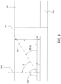
- FIG. 8 illustrates one of the plurality of LEDs 102 (hereinafter referred to interchangeably as LED 102) and one of the mounting holes 104 (hereinafter referred to interchangeably mounting hole 104) placed adjacent to the LED 102.
- the LED 102 sits on top of the extrusion 108 and under the lens 106.
- Equation (1) illustrated in one embodiment by FIG. 8 h represents a height of the mounting hole 104 from a top of the extrusion 108, d represents the distance between the LED 102 and the mounting hole 104.
- the symbol ⁇ represents a viewing angle of light from the LED 102.
- the symbol ⁇ may also represent a viewing angle of light from a combination of the LED 102 and a secondary optic (not shown).
- ⁇ may be an angle of light emitted from the LED 102 spanning from a vertical axis represented by a dashed line 802 of light emitted by one of the plurality of LEDs 102 to the top of the mounting hole 104 represented by a dashed line 804.
- the term 90- ⁇ represents the angle of light blocked by the height of the mounting hole 104.
- Equation (2) h is a known height of the mounting hole 104 and ⁇ may be calculated based on the known height of the mounting hole 104.
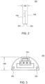
- FIG. 2 illustrates a side view of the lighting fixture 100 that helps to illustrate the design profile of the lens 106 and the extrusion 108.
- a height 202 of the lens 106 is greater than a height 204 of the extrusion 108.
- the ratio of the height 202 of the lens 106 to the height 204 of the extrusion 108 is greater than one.
- a combined height 206 of the height 202 of the lens 106 and the height 204 of the extrusion is less than 2.54 cm. In one embodiment, the combined height may be less than 1.27 cm.
- the extrusion 108 may function as a flat heat sink.
- the thickness of the heat sink, and thereby the extrusion 108 may be a function of a spacing length of the uniform spacing the plurality of LEDs 102. For example, as the length of the uniform spacing between the plurality of LEDs 102 increases, the thickness of the heat sink and the extrusion 108 will decrease. Conversely, as the length of the uniform spacing between the plurality of LEDs 102 decreases, the thickness of the heat sink and the extrusion 108 will increase.
- the lens 106 may be fabricated from polycarbonate. However, one skilled in the art will recognize that any optical grade material may be used.
- the lens 106 may include various optical features depending on the application of the lighting fixture 100.
- a masking (now shown) may be applied on both sides along a length of the lens 106. The masking helps to achieve a narrower angle of light output from the plurality of LEDs 102 and helps to prevent glare.
- a color added pigment recipe may be included in the lens 106 depending on the various lighting requirements.
- the pigment may be used to precisely control the direction of the photons emitted from the plurality of LEDs 102. For example, the pigment may help to spread light more uniformly over a wider distance at a cost of lower efficiency.
- the lens 106 may also be any shape in accordance with a desired application of the light fixture 100.
- the lens 106 is a hemisphere shape to achieve the greatest pass through of light outputted by the plurality of LEDs 102.
- the lens 106 may be a different shape, for example, depending on if one desires the light output of the plurality of LEDs 102 to be wider or narrower.
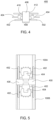
- FIG. 3 illustrates a front view of one end 300 of the light fixture 100.
- FIG. 3 also helps to illustrate the ultra low profile (i.e. the combined height 206 of the lens 106 and the extrusion 108 of the light fixture 100, as described above.
- the ultra low profile i.e. the combined height 206 of the lens 106 and the extrusion 108 of the light fixture 100, as described above.
- an opposing end of the light fixture 100 will be substantially similar to the end 300 illustrated in FIG. 3 .
- the end 300 comprises one or more holes 302 for receiving an alignment post of an end-to-end connector described below.
- the end 300 also comprises one or more holes 304 for receiving a connecting pin of the end-to-end connector, also further described below.
- the end 300 of the lighting fixture 100 is designed such that multiple light fixtures 100 may be coupled together in an end-to-end fashion. In doing so, an end-to-end connector is used to allow the uniform spacing of the plurality of LEDs 102 to be maintained between the multiple light fixtures 100.
- FIG. 4 illustrates one embodiment of an end-to-end connector.
- the end-to-end connector 400 comprises a spacer 406, a first side 410 coupled to the spacer 406 for coupling to a first light fixture 100 and a second side 412 coupled to the spacer 406 for coupling to a second light fixture 100.
- the spacer 406 may be made of any material.
- the spacer 406 may have a width such that when connecting two light fixtures 100, the LEDs 102 maintain a uniform spacing across the two light fixtures 100.
- the first side 410 and the second side 412 each comprises one or more alignment posts 402 and one or more connecting pins 404 coupled to the respective side.
- the alignment posts 402 are designed to bear most of stress and weight of the connection to a lighting fixture 100 as the connecting pin 404 may generally be a more delicate piece of hardware.
- the alignment posts 402 provide for easier alignment between the end-to-end connector 400 and the light fixture 100. As discussed above, the alignment posts 402 mate with the holes 302. Similarly, the connecting pins 404 mate with the holes 304. As a result, a flush connection is achieved between the light fixture 100 and the end-to-end connector 400.
- the alignment posts 402 may be a single post that is pushed through the first side 410, the spacer 406 and the second side 412.
- FIG. 5 illustrates one embodiment of the end-to-end connector 400 coupled to two light fixtures 100A and 100B.
- An important feature of the end-to-end connector 400 is that it maintains uniform spacing of the plurality of LEDs (not shown) between the multiple light fixtures 100A and 100B, as discussed above. More specifically, the uniform spacing is maintained between a last one of the plurality of LEDs (not shown) of a first light fixture 100A and a first one of the plurality of LEDs (not shown) of a second light fixture 100B. In other words, a length between each one of the LEDs across the first light fixture 100A and the second light fixture 100B is the same.
- multiple spacers 406 may be used to connect any number of light fixtures 100 end-to-end while maintaining uniform spacing between all of the LEDs.
- a width 408 of the spacer 406 is a function of the desired uniform spacing between a plurality of LEDs of each light fixture 100A and 100B. For example, if the desired uniform spacing is approximately 275 mm, then the width 408 of the spacer 406 would be the precise length required to maintain the uniform 275 mm spacing between the last one of the LEDs of a first light fixture 100A and the first one of the plurality of LEDs of a second light fixture 100B. This may be repeated with numerous light fixtures 100 and end-to-end connectors 400 over a long length, for example, over 6 metres. Thus, the width 408 of the spacer 406 may be manufactured in various sizes in accordance with the desired uniform spacing between the plurality of LEDs across multiple light fixtures 100A and 100B.
- FIG. 6 illustrates a second embodiment of an end-to-end connector 600 used with the light fixture 100 described herein.
- the end-to-end connector 600 includes a first interface 606 for coupling to a first light fixture 100 and a second interface 608 for coupling to a second light fixture 100.
- the first interface 606 and second interface 608 are coupled to a flexible cord 610.
- the end-to-end connector 600 may be used to run parallel rows of light fixtures 100 in conjunction with the end-to-end connector 400 described above.
- the first interface 606 may comprise one or more alignment posts 602 and one or more connecting pins 604. Similar to the end-to-end connector 400, the alignment posts 602 are designed to bear most of stress and weight of the connection to a lighting fixture 100 as the connecting pin 604 may generally be a more delicate piece of hardware. In addition, the alignment posts 602 provide for easier alignment between the end-to-end connector 600 and the light fixture 100. As discussed above, the alignment posts 602 mate with the holes 302. Similarly, the connecting pins 604 mate with the holes 304. As a result, a flush connection is achieved between the light fixture 100 and the end-to-end connector 600.
- the second interface 608 may also comprise one or more alignment posts 602 and one or more connecting pins 604.
- the end-to-end connector 600 also serves to maintain uniformity.
- the end-to-end connector 600 aligns light fixtures 100 in parallel, as discussed above. For example, this is illustrated by FIG. 7 .
- end-to-end connector 600 is coupled to light fixtures 100A and 100B.
- the flexible cord 610 allows the end-to-end connector 600 to bend, thereby, running light the fixtures 100A and 100B in parallel.
- the light fixtures 100A and 100B are aligned vertically. That is each one of the plurality of LEDs 102A are vertically aligned with the LEDs 102B, thus maintaining a symmetric illumination pattern.
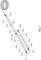
- FIG. 7 illustrates the end-to-end connector 400 connected to the light fixture 100A and the light fixture 100C.
- the end-to-end connector 400 maintains a uniform spacing between the last or furthest right LED 102A of the light fixture 100A and the first or furthest left LED 102C of the light fixture 100C. That is the spacing between each one of the LEDs 102A and 102C is uniform, even between the LED 102A and the LED 102C across the end-to-end connector 400.
- the end-to-end connector 600 may be sized to achieve the same functionality as the end-to-end connector 400.
- the end-to-end connector 600 may be sized to be used interchangeably with the end-to-end connector 400, if necessary, to maintain a uniform spacing between the plurality of LEDs 102A and 102C.
Landscapes
- Engineering & Computer Science (AREA)
- General Engineering & Computer Science (AREA)
- Physics & Mathematics (AREA)
- Spectroscopy & Molecular Physics (AREA)
- Non-Portable Lighting Devices Or Systems Thereof (AREA)
- Fastening Of Light Sources Or Lamp Holders (AREA)
Claims (6)
- Leuchtvorrichtung, Folgendes umfassend:eine Extrusion (108);eine Vielzahl von lichtemittierenden Dioden, LEDs (102), die einen gleichmäßigen Abstand zwischen jeder der Vielzahl von LEDs (102) entlang der Extrusion (108) aufweisen; undeine Linse (106), die mit der Extrusion (108) gekoppelt ist,dadurch gekennzeichnet, dass sie ferner Folgendes umfasst:ein oder mehrere Befestigungslöcher (104), wobei das oder jedes Befestigungsloch (104) durch die Linse (106) und die Extrusion (108) als ein einziges Loch (104) verläuft, und wobei die Befestigungslöcher (104) und die LEDs (102) entlang einer zentralen Längsachse der Linse (106) positioniert sind, wobei das oder jedes Befestigungsloch (104) in einem Abstand d von einer entsprechenden LED platziert ist, um dunkle Stellen zu vermeiden und die optische Effizienz auf einem gezielten Beleuchtungsbereich zu maximieren,worin d= h/tan(90 - σ), undh eine Höhe des Befestigungslochs (104) über einer Oberseite der Extrusion (108) ist, undσ ein Winkel des von der LED (102) emittierten Lichts ist, der sich von einer vertikalen Achse (802) bis zur Oberseite des Befestigungslochs (104) erstreckt, und wobei die vertikale Achse (802) senkrecht zu der Längsachse der Linse (106) ist.
- Leuchtvorrichtung nach Anspruch 1, wobei die Extrusion (108) einen Kühlkörper umfasst.
- Leuchtvorrichtung nach Anspruch 1, wobei die Höhe der Linse (106) größer ist als die Höhe der Extrusion (108).
- Leuchtvorrichtung nach Anspruch 1, wobei der gleichmäßige Abstand ungefähr zwischen 100 Millimetern (mm) und 500 mm liegt.
- Leuchtvorrichtung nach einem der vorhergehenden Ansprüche, wobei die kombinierte Höhe aus der Höhe der Linse (106) und der Höhe der Extrusion (108) weniger als 2,54 cm beträgt.
- Leuchtvorrichtung nach Anspruch 5, wobei die kombinierte Höhe aus der Höhe der Linse (106) und der Höhe der Extrusion (108) weniger als 1,27 cm beträgt.
Applications Claiming Priority (2)
| Application Number | Priority Date | Filing Date | Title |
|---|---|---|---|
| US12/370,871 US8231245B2 (en) | 2009-02-13 | 2009-02-13 | LED lighting fixture |
| PCT/US2010/023920 WO2010093807A1 (en) | 2009-02-13 | 2010-02-11 | Led lighting fixture |
Publications (3)
| Publication Number | Publication Date |
|---|---|
| EP2396591A1 EP2396591A1 (de) | 2011-12-21 |
| EP2396591A4 EP2396591A4 (de) | 2013-07-17 |
| EP2396591B1 true EP2396591B1 (de) | 2023-07-05 |
Family
ID=42559747
Family Applications (1)
| Application Number | Title | Priority Date | Filing Date |
|---|---|---|---|
| EP10741732.1A Active EP2396591B1 (de) | 2009-02-13 | 2010-02-11 | Led-leuchte |
Country Status (3)
| Country | Link |
|---|---|
| US (1) | US8231245B2 (de) |
| EP (1) | EP2396591B1 (de) |
| WO (1) | WO2010093807A1 (de) |
Families Citing this family (16)
| Publication number | Priority date | Publication date | Assignee | Title |
|---|---|---|---|---|
| AT13052U1 (de) * | 2011-02-17 | 2013-05-15 | Tridonic Connection Technology Gmbh & Co Kg | Vorrichtung zum verbinden und kontaktieren zumindest einer led-einheit, sowie led-einheit und leuchtsystem |
| US8545045B2 (en) * | 2011-07-12 | 2013-10-01 | Rev-A-Shelf Company, Llc | Modular LED lighting systems and kits |
| JP2013115005A (ja) * | 2011-11-30 | 2013-06-10 | Toshiba Lighting & Technology Corp | 照明装置 |
| US9423116B2 (en) * | 2013-12-11 | 2016-08-23 | Cree, Inc. | LED lamp and modular lighting system |
| CN105098492B (zh) * | 2014-05-21 | 2017-05-03 | 纬创资通股份有限公司 | 具有导孔结构、导柱结构的连接器机构及电子装置组合件 |
| US10006615B2 (en) | 2014-05-30 | 2018-06-26 | Oelo, LLC | Lighting system and method of use |
| US9520742B2 (en) | 2014-07-03 | 2016-12-13 | Hubbell Incorporated | Monitoring system and method |
| USD760418S1 (en) | 2014-07-03 | 2016-06-28 | Appleton Grp Llc | LED lighting housing |
| US9494301B2 (en) | 2014-07-03 | 2016-11-15 | Appleton Grp Llc | Lighting housing having self-adjusting hinge mechanism |
| USD787112S1 (en) * | 2015-07-30 | 2017-05-16 | Moda LLC | Cove lighting fixture |
| USD850700S1 (en) | 2018-05-07 | 2019-06-04 | Moda LLC | Internal lighting fixture |
| WO2020252686A1 (zh) * | 2019-06-19 | 2020-12-24 | 厦门普为光电科技有限公司 | 高散热效能的灯具 |
| USD940945S1 (en) * | 2019-09-19 | 2022-01-11 | Changzhou Kaisen Photoelectricity Co., Ltd. | LED light |
| USD1101244S1 (en) | 2024-03-19 | 2025-11-04 | Ip Llc A Series Of Moda Light Llc | Exterior light fixture |
| USD1116214S1 (en) | 2024-10-17 | 2026-03-03 | Ip Llc A Series Of Moda Light Llc | Interior light fixture |
| USD1116215S1 (en) | 2024-10-17 | 2026-03-03 | Ip Llc A Series Of Moda Light Llc | Exterior light fixture |
Citations (1)
| Publication number | Priority date | Publication date | Assignee | Title |
|---|---|---|---|---|
| WO2008137618A1 (en) * | 2007-05-07 | 2008-11-13 | Koninklijke Philips Electronics N V | Led-based lighting fixtures for surface illumination with improved heat dissipation and manufacturability |
Family Cites Families (11)
| Publication number | Priority date | Publication date | Assignee | Title |
|---|---|---|---|---|
| GB2361988B (en) * | 2000-05-05 | 2004-03-03 | Avimo Ltd | Illumination system |
| US6871981B2 (en) * | 2001-09-13 | 2005-03-29 | Heads Up Technologies, Inc. | LED lighting device and system |
| US6932495B2 (en) * | 2001-10-01 | 2005-08-23 | Sloanled, Inc. | Channel letter lighting using light emitting diodes |
| US6880952B2 (en) * | 2002-03-18 | 2005-04-19 | Wintriss Engineering Corporation | Extensible linear light emitting diode illumination source |
| AU2003234661A1 (en) * | 2002-06-03 | 2003-12-19 | Everbrite, Inc. | Led accent lighting units |
| US7329024B2 (en) | 2003-09-22 | 2008-02-12 | Permlight Products, Inc. | Lighting apparatus |
| US7159997B2 (en) * | 2004-12-30 | 2007-01-09 | Lo Lighting | Linear lighting apparatus with increased light-transmission efficiency |
| KR100516123B1 (ko) * | 2005-08-30 | 2005-09-21 | 주식회사 누리플랜 | 라인형 엘이디 조명등 |
| TWM309051U (en) * | 2006-06-12 | 2007-04-01 | Grand Halo Technology Co Ltd | Light-emitting device |
| KR20090096429A (ko) | 2006-10-19 | 2009-09-10 | 필립스 솔리드-스테이트 라이팅 솔루션스, 인크. | 조명 설비, 모듈식 led 기반 조명 설비, 선형 조명 설비 및 조명 시스템 |
| DE112006004179B4 (de) * | 2006-12-28 | 2016-10-06 | Friedemann Hoffmann | Beleuchtungsvorrichtung |
-
2009
- 2009-02-13 US US12/370,871 patent/US8231245B2/en active Active
-
2010
- 2010-02-11 EP EP10741732.1A patent/EP2396591B1/de active Active
- 2010-02-11 WO PCT/US2010/023920 patent/WO2010093807A1/en not_active Ceased
Patent Citations (1)
| Publication number | Priority date | Publication date | Assignee | Title |
|---|---|---|---|---|
| WO2008137618A1 (en) * | 2007-05-07 | 2008-11-13 | Koninklijke Philips Electronics N V | Led-based lighting fixtures for surface illumination with improved heat dissipation and manufacturability |
Also Published As
| Publication number | Publication date |
|---|---|
| EP2396591A1 (de) | 2011-12-21 |
| WO2010093807A1 (en) | 2010-08-19 |
| US20100208458A1 (en) | 2010-08-19 |
| US8231245B2 (en) | 2012-07-31 |
| EP2396591A4 (de) | 2013-07-17 |
Similar Documents
| Publication | Publication Date | Title |
|---|---|---|
| EP2396591B1 (de) | Led-leuchte | |
| US9423116B2 (en) | LED lamp and modular lighting system | |
| US8858028B2 (en) | LED lighting apparatus | |
| CN101680620B (zh) | 光学器件保持和定位设备以及照明组件 | |
| EP2553316B1 (de) | Led-lichtröhre mit doppelseitiger lichtverteilung | |
| US8308320B2 (en) | Light emitting diode modules with male/female features for end-to-end coupling | |
| US8602604B2 (en) | Extruded wide angle lens for use with a LED light source | |
| US7926977B2 (en) | LED lighting system for a cabinet sign | |
| EP1664621B1 (de) | Mit leuchtdioden versehener stab | |
| US8919991B2 (en) | Tube-type LED illumination lamp | |
| EP2591277B1 (de) | Unabhängige module zum austauschen einer fluoreszenten led-röhre | |
| US20150345712A1 (en) | Led linear lamp with up and down illumination | |
| WO2008132941A1 (ja) | 発光装置、および表示装置 | |
| US10508797B2 (en) | Luminaire and connection mechanism for connecting multiple luminaires | |
| US9133989B2 (en) | Mechanical attachment system for linear light modules | |
| DE202010001126U1 (de) | LED-Leuchtvorrichtung zur Erhöhung der Beleuchtungsstärke | |
| DE202010001128U1 (de) | LED-Leuchtvorrichtung mit größerem Leuchtwinkel | |
| EP3093552B1 (de) | Verbindungsvorrichtung für eine leuchte und entsprechendes verfahren | |
| EP2499426A1 (de) | Grundträger, lichtquellenträger und system aus grundträger und lichtquellenträger | |
| WO2013168838A1 (ko) | 중앙부에서 가장자리로 균일도를 제어하는 도광판 구조 및 이를 이용한 조명등 | |
| WO2012128547A2 (ko) | Led 램프 | |
| EP2589853A1 (de) | Beleuchtungsmodul und Leuchtvorrichtung, die solche Beleuchtungsmodule umfass | |
| DE202009017520U1 (de) | LED-Leuchtvorrichtung mit einstellbarem Leuchtwinkel | |
| KR20150117007A (ko) | Led군집의 배광 제어용 렌즈 광학계 및 이를 포함하는 led군집 조명 | |
| KR102221600B1 (ko) | 조명 장치 |
Legal Events
| Date | Code | Title | Description |
|---|---|---|---|
| PUAI | Public reference made under article 153(3) epc to a published international application that has entered the european phase |
Free format text: ORIGINAL CODE: 0009012 |
|
| 17P | Request for examination filed |
Effective date: 20110912 |
|
| AK | Designated contracting states |
Kind code of ref document: A1 Designated state(s): AT BE BG CH CY CZ DE DK EE ES FI FR GB GR HR HU IE IS IT LI LT LU LV MC MK MT NL NO PL PT RO SE SI SK SM TR |
|
| DAX | Request for extension of the european patent (deleted) | ||
| A4 | Supplementary search report drawn up and despatched |
Effective date: 20130617 |
|
| RIC1 | Information provided on ipc code assigned before grant |
Ipc: F21V 29/00 20060101ALN20130611BHEP Ipc: F21S 4/00 20060101AFI20130611BHEP Ipc: F21V 21/005 20060101ALN20130611BHEP Ipc: F21V 5/04 20060101ALI20130611BHEP Ipc: H01R 25/16 20060101ALN20130611BHEP Ipc: F21V 23/06 20060101ALN20130611BHEP Ipc: F21Y 101/02 20060101ALI20130611BHEP Ipc: F21V 15/01 20060101ALI20130611BHEP |
|
| 17Q | First examination report despatched |
Effective date: 20160811 |
|
| STAA | Information on the status of an ep patent application or granted ep patent |
Free format text: STATUS: EXAMINATION IS IN PROGRESS |
|
| REG | Reference to a national code |
Ref country code: DE Ref legal event code: R079 Ref document number: 602010068902 Country of ref document: DE Free format text: PREVIOUS MAIN CLASS: F21S0002000000 Ipc: F21S0004280000 Ref country code: DE Ref legal event code: R079 Free format text: PREVIOUS MAIN CLASS: F21S0002000000 Ipc: F21S0004280000 |
|
| RIC1 | Information provided on ipc code assigned before grant |
Ipc: F21V 21/02 20060101ALI20221025BHEP Ipc: F21V 9/08 20060101ALI20221025BHEP Ipc: F21V 23/06 20060101ALI20221025BHEP Ipc: F21V 21/005 20060101ALI20221025BHEP Ipc: F21V 5/04 20060101ALI20221025BHEP Ipc: F21V 29/507 20150101ALI20221025BHEP Ipc: F21V 29/70 20150101ALI20221025BHEP Ipc: F21V 15/01 20060101ALI20221025BHEP Ipc: F21S 4/28 20160101AFI20221025BHEP |
|
| GRAP | Despatch of communication of intention to grant a patent |
Free format text: ORIGINAL CODE: EPIDOSNIGR1 |
|
| STAA | Information on the status of an ep patent application or granted ep patent |
Free format text: STATUS: GRANT OF PATENT IS INTENDED |
|
| INTG | Intention to grant announced |
Effective date: 20230125 |
|
| RIN1 | Information on inventor provided before grant (corrected) |
Inventor name: BOEGE, SAMUAL DAVID Inventor name: ROUTLEDGE, GORDON Inventor name: SHASTRY, CHAKRAKODI VISHNU Inventor name: WEIMER, DAVID Inventor name: LEIB III, WILLIAM S. |
|
| GRAS | Grant fee paid |
Free format text: ORIGINAL CODE: EPIDOSNIGR3 |
|
| GRAA | (expected) grant |
Free format text: ORIGINAL CODE: 0009210 |
|
| STAA | Information on the status of an ep patent application or granted ep patent |
Free format text: STATUS: THE PATENT HAS BEEN GRANTED |
|
| P01 | Opt-out of the competence of the unified patent court (upc) registered |
Effective date: 20230524 |
|
| AK | Designated contracting states |
Kind code of ref document: B1 Designated state(s): AT BE BG CH CY CZ DE DK EE ES FI FR GB GR HR HU IE IS IT LI LT LU LV MC MK MT NL NO PL PT RO SE SI SK SM TR |
|
| REG | Reference to a national code |
Ref country code: GB Ref legal event code: FG4D |
|
| REG | Reference to a national code |
Ref country code: CH Ref legal event code: EP |
|
| REG | Reference to a national code |
Ref country code: AT Ref legal event code: REF Ref document number: 1585142 Country of ref document: AT Kind code of ref document: T Effective date: 20230715 |
|
| REG | Reference to a national code |
Ref country code: DE Ref legal event code: R096 Ref document number: 602010068902 Country of ref document: DE |
|
| REG | Reference to a national code |
Ref country code: IE Ref legal event code: FG4D |
|
| REG | Reference to a national code |
Ref country code: LT Ref legal event code: MG9D |
|
| REG | Reference to a national code |
Ref country code: NL Ref legal event code: MP Effective date: 20230705 |
|
| REG | Reference to a national code |
Ref country code: AT Ref legal event code: MK05 Ref document number: 1585142 Country of ref document: AT Kind code of ref document: T Effective date: 20230705 |
|
| PG25 | Lapsed in a contracting state [announced via postgrant information from national office to epo] |
Ref country code: NL Free format text: LAPSE BECAUSE OF FAILURE TO SUBMIT A TRANSLATION OF THE DESCRIPTION OR TO PAY THE FEE WITHIN THE PRESCRIBED TIME-LIMIT Effective date: 20230705 |
|
| PG25 | Lapsed in a contracting state [announced via postgrant information from national office to epo] |
Ref country code: GR Free format text: LAPSE BECAUSE OF FAILURE TO SUBMIT A TRANSLATION OF THE DESCRIPTION OR TO PAY THE FEE WITHIN THE PRESCRIBED TIME-LIMIT Effective date: 20231006 |
|
| PG25 | Lapsed in a contracting state [announced via postgrant information from national office to epo] |
Ref country code: ES Free format text: LAPSE BECAUSE OF FAILURE TO SUBMIT A TRANSLATION OF THE DESCRIPTION OR TO PAY THE FEE WITHIN THE PRESCRIBED TIME-LIMIT Effective date: 20230705 |
|
| PG25 | Lapsed in a contracting state [announced via postgrant information from national office to epo] |
Ref country code: IS Free format text: LAPSE BECAUSE OF FAILURE TO SUBMIT A TRANSLATION OF THE DESCRIPTION OR TO PAY THE FEE WITHIN THE PRESCRIBED TIME-LIMIT Effective date: 20231105 |
|
| PG25 | Lapsed in a contracting state [announced via postgrant information from national office to epo] |
Ref country code: SE Free format text: LAPSE BECAUSE OF FAILURE TO SUBMIT A TRANSLATION OF THE DESCRIPTION OR TO PAY THE FEE WITHIN THE PRESCRIBED TIME-LIMIT Effective date: 20230705 Ref country code: PT Free format text: LAPSE BECAUSE OF FAILURE TO SUBMIT A TRANSLATION OF THE DESCRIPTION OR TO PAY THE FEE WITHIN THE PRESCRIBED TIME-LIMIT Effective date: 20231106 Ref country code: NO Free format text: LAPSE BECAUSE OF FAILURE TO SUBMIT A TRANSLATION OF THE DESCRIPTION OR TO PAY THE FEE WITHIN THE PRESCRIBED TIME-LIMIT Effective date: 20231005 Ref country code: LV Free format text: LAPSE BECAUSE OF FAILURE TO SUBMIT A TRANSLATION OF THE DESCRIPTION OR TO PAY THE FEE WITHIN THE PRESCRIBED TIME-LIMIT Effective date: 20230705 Ref country code: LT Free format text: LAPSE BECAUSE OF FAILURE TO SUBMIT A TRANSLATION OF THE DESCRIPTION OR TO PAY THE FEE WITHIN THE PRESCRIBED TIME-LIMIT Effective date: 20230705 Ref country code: IS Free format text: LAPSE BECAUSE OF FAILURE TO SUBMIT A TRANSLATION OF THE DESCRIPTION OR TO PAY THE FEE WITHIN THE PRESCRIBED TIME-LIMIT Effective date: 20231105 Ref country code: HR Free format text: LAPSE BECAUSE OF FAILURE TO SUBMIT A TRANSLATION OF THE DESCRIPTION OR TO PAY THE FEE WITHIN THE PRESCRIBED TIME-LIMIT Effective date: 20230705 Ref country code: GR Free format text: LAPSE BECAUSE OF FAILURE TO SUBMIT A TRANSLATION OF THE DESCRIPTION OR TO PAY THE FEE WITHIN THE PRESCRIBED TIME-LIMIT Effective date: 20231006 Ref country code: FI Free format text: LAPSE BECAUSE OF FAILURE TO SUBMIT A TRANSLATION OF THE DESCRIPTION OR TO PAY THE FEE WITHIN THE PRESCRIBED TIME-LIMIT Effective date: 20230705 Ref country code: ES Free format text: LAPSE BECAUSE OF FAILURE TO SUBMIT A TRANSLATION OF THE DESCRIPTION OR TO PAY THE FEE WITHIN THE PRESCRIBED TIME-LIMIT Effective date: 20230705 Ref country code: AT Free format text: LAPSE BECAUSE OF FAILURE TO SUBMIT A TRANSLATION OF THE DESCRIPTION OR TO PAY THE FEE WITHIN THE PRESCRIBED TIME-LIMIT Effective date: 20230705 |
|
| PG25 | Lapsed in a contracting state [announced via postgrant information from national office to epo] |
Ref country code: PL Free format text: LAPSE BECAUSE OF FAILURE TO SUBMIT A TRANSLATION OF THE DESCRIPTION OR TO PAY THE FEE WITHIN THE PRESCRIBED TIME-LIMIT Effective date: 20230705 |
|
| REG | Reference to a national code |
Ref country code: DE Ref legal event code: R097 Ref document number: 602010068902 Country of ref document: DE |
|
| PG25 | Lapsed in a contracting state [announced via postgrant information from national office to epo] |
Ref country code: SM Free format text: LAPSE BECAUSE OF FAILURE TO SUBMIT A TRANSLATION OF THE DESCRIPTION OR TO PAY THE FEE WITHIN THE PRESCRIBED TIME-LIMIT Effective date: 20230705 Ref country code: RO Free format text: LAPSE BECAUSE OF FAILURE TO SUBMIT A TRANSLATION OF THE DESCRIPTION OR TO PAY THE FEE WITHIN THE PRESCRIBED TIME-LIMIT Effective date: 20230705 Ref country code: EE Free format text: LAPSE BECAUSE OF FAILURE TO SUBMIT A TRANSLATION OF THE DESCRIPTION OR TO PAY THE FEE WITHIN THE PRESCRIBED TIME-LIMIT Effective date: 20230705 Ref country code: DK Free format text: LAPSE BECAUSE OF FAILURE TO SUBMIT A TRANSLATION OF THE DESCRIPTION OR TO PAY THE FEE WITHIN THE PRESCRIBED TIME-LIMIT Effective date: 20230705 Ref country code: CZ Free format text: LAPSE BECAUSE OF FAILURE TO SUBMIT A TRANSLATION OF THE DESCRIPTION OR TO PAY THE FEE WITHIN THE PRESCRIBED TIME-LIMIT Effective date: 20230705 Ref country code: SK Free format text: LAPSE BECAUSE OF FAILURE TO SUBMIT A TRANSLATION OF THE DESCRIPTION OR TO PAY THE FEE WITHIN THE PRESCRIBED TIME-LIMIT Effective date: 20230705 |
|
| PLBE | No opposition filed within time limit |
Free format text: ORIGINAL CODE: 0009261 |
|
| STAA | Information on the status of an ep patent application or granted ep patent |
Free format text: STATUS: NO OPPOSITION FILED WITHIN TIME LIMIT |
|
| PG25 | Lapsed in a contracting state [announced via postgrant information from national office to epo] |
Ref country code: IT Free format text: LAPSE BECAUSE OF FAILURE TO SUBMIT A TRANSLATION OF THE DESCRIPTION OR TO PAY THE FEE WITHIN THE PRESCRIBED TIME-LIMIT Effective date: 20230705 |
|
| 26N | No opposition filed |
Effective date: 20240408 |
|
| PG25 | Lapsed in a contracting state [announced via postgrant information from national office to epo] |
Ref country code: SI Free format text: LAPSE BECAUSE OF FAILURE TO SUBMIT A TRANSLATION OF THE DESCRIPTION OR TO PAY THE FEE WITHIN THE PRESCRIBED TIME-LIMIT Effective date: 20230705 |
|
| PG25 | Lapsed in a contracting state [announced via postgrant information from national office to epo] |
Ref country code: MC Free format text: LAPSE BECAUSE OF FAILURE TO SUBMIT A TRANSLATION OF THE DESCRIPTION OR TO PAY THE FEE WITHIN THE PRESCRIBED TIME-LIMIT Effective date: 20230705 |
|
| REG | Reference to a national code |
Ref country code: CH Ref legal event code: PL |
|
| PG25 | Lapsed in a contracting state [announced via postgrant information from national office to epo] |
Ref country code: LU Free format text: LAPSE BECAUSE OF NON-PAYMENT OF DUE FEES Effective date: 20240211 |
|
| PG25 | Lapsed in a contracting state [announced via postgrant information from national office to epo] |
Ref country code: CH Free format text: LAPSE BECAUSE OF NON-PAYMENT OF DUE FEES Effective date: 20240229 |
|
| PG25 | Lapsed in a contracting state [announced via postgrant information from national office to epo] |
Ref country code: LU Free format text: LAPSE BECAUSE OF NON-PAYMENT OF DUE FEES Effective date: 20240211 Ref country code: CH Free format text: LAPSE BECAUSE OF NON-PAYMENT OF DUE FEES Effective date: 20240229 |
|
| PG25 | Lapsed in a contracting state [announced via postgrant information from national office to epo] |
Ref country code: BG Free format text: LAPSE BECAUSE OF FAILURE TO SUBMIT A TRANSLATION OF THE DESCRIPTION OR TO PAY THE FEE WITHIN THE PRESCRIBED TIME-LIMIT Effective date: 20230705 |
|
| PG25 | Lapsed in a contracting state [announced via postgrant information from national office to epo] |
Ref country code: BG Free format text: LAPSE BECAUSE OF FAILURE TO SUBMIT A TRANSLATION OF THE DESCRIPTION OR TO PAY THE FEE WITHIN THE PRESCRIBED TIME-LIMIT Effective date: 20230705 |
|
| REG | Reference to a national code |
Ref country code: BE Ref legal event code: MM Effective date: 20240229 |
|
| PG25 | Lapsed in a contracting state [announced via postgrant information from national office to epo] |
Ref country code: BE Free format text: LAPSE BECAUSE OF NON-PAYMENT OF DUE FEES Effective date: 20240229 |
|
| PG25 | Lapsed in a contracting state [announced via postgrant information from national office to epo] |
Ref country code: IE Free format text: LAPSE BECAUSE OF NON-PAYMENT OF DUE FEES Effective date: 20240211 |
|
| PG25 | Lapsed in a contracting state [announced via postgrant information from national office to epo] |
Ref country code: IE Free format text: LAPSE BECAUSE OF NON-PAYMENT OF DUE FEES Effective date: 20240211 Ref country code: BE Free format text: LAPSE BECAUSE OF NON-PAYMENT OF DUE FEES Effective date: 20240229 |
|
| PG25 | Lapsed in a contracting state [announced via postgrant information from national office to epo] |
Ref country code: CY Free format text: LAPSE BECAUSE OF FAILURE TO SUBMIT A TRANSLATION OF THE DESCRIPTION OR TO PAY THE FEE WITHIN THE PRESCRIBED TIME-LIMIT; INVALID AB INITIO Effective date: 20100211 |
|
| PG25 | Lapsed in a contracting state [announced via postgrant information from national office to epo] |
Ref country code: HU Free format text: LAPSE BECAUSE OF FAILURE TO SUBMIT A TRANSLATION OF THE DESCRIPTION OR TO PAY THE FEE WITHIN THE PRESCRIBED TIME-LIMIT; INVALID AB INITIO Effective date: 20100211 |
|
| PG25 | Lapsed in a contracting state [announced via postgrant information from national office to epo] |
Ref country code: TR Free format text: LAPSE BECAUSE OF FAILURE TO SUBMIT A TRANSLATION OF THE DESCRIPTION OR TO PAY THE FEE WITHIN THE PRESCRIBED TIME-LIMIT Effective date: 20230705 |
|
| PGFP | Annual fee paid to national office [announced via postgrant information from national office to epo] |
Ref country code: GB Payment date: 20260113 Year of fee payment: 17 |
|
| PGFP | Annual fee paid to national office [announced via postgrant information from national office to epo] |
Ref country code: DE Payment date: 20260115 Year of fee payment: 17 |
|
| PGFP | Annual fee paid to national office [announced via postgrant information from national office to epo] |
Ref country code: FR Payment date: 20260109 Year of fee payment: 17 |