EP2396501B1 - Werkzeug zur stufenweisen zementierung - Google Patents
Werkzeug zur stufenweisen zementierung Download PDFInfo
- Publication number
- EP2396501B1 EP2396501B1 EP10703670.9A EP10703670A EP2396501B1 EP 2396501 B1 EP2396501 B1 EP 2396501B1 EP 10703670 A EP10703670 A EP 10703670A EP 2396501 B1 EP2396501 B1 EP 2396501B1
- Authority
- EP
- European Patent Office
- Prior art keywords
- closing sleeve
- cementing
- cementing tool
- locking
- housing
- Prior art date
- Legal status (The legal status is an assumption and is not a legal conclusion. Google has not performed a legal analysis and makes no representation as to the accuracy of the status listed.)
- Not-in-force
Links
- 239000004568 cement Substances 0.000 description 18
- 239000012530 fluid Substances 0.000 description 6
- 238000011282 treatment Methods 0.000 description 5
- 230000015572 biosynthetic process Effects 0.000 description 3
- 238000000034 method Methods 0.000 description 3
- 230000000638 stimulation Effects 0.000 description 3
- 230000015556 catabolic process Effects 0.000 description 2
- 238000006073 displacement reaction Methods 0.000 description 2
- 238000005553 drilling Methods 0.000 description 2
- 238000002955 isolation Methods 0.000 description 2
- 239000004215 Carbon black (E152) Substances 0.000 description 1
- 238000010276 construction Methods 0.000 description 1
- 238000006731 degradation reaction Methods 0.000 description 1
- 230000000694 effects Effects 0.000 description 1
- 229930195733 hydrocarbon Natural products 0.000 description 1
- 150000002430 hydrocarbons Chemical class 0.000 description 1
- 230000014759 maintenance of location Effects 0.000 description 1
- 230000004936 stimulating effect Effects 0.000 description 1
Images




Classifications
-
- E—FIXED CONSTRUCTIONS
- E21—EARTH OR ROCK DRILLING; MINING
- E21B—EARTH OR ROCK DRILLING; OBTAINING OIL, GAS, WATER, SOLUBLE OR MELTABLE MATERIALS OR A SLURRY OF MINERALS FROM WELLS
- E21B33/00—Sealing or packing boreholes or wells
- E21B33/10—Sealing or packing boreholes or wells in the borehole
- E21B33/13—Methods or devices for cementing, for plugging holes, crevices or the like
- E21B33/14—Methods or devices for cementing, for plugging holes, crevices or the like for cementing casings into boreholes
- E21B33/146—Stage cementing, i.e. discharging cement from casing at different levels
-
- E—FIXED CONSTRUCTIONS
- E21—EARTH OR ROCK DRILLING; MINING
- E21B—EARTH OR ROCK DRILLING; OBTAINING OIL, GAS, WATER, SOLUBLE OR MELTABLE MATERIALS OR A SLURRY OF MINERALS FROM WELLS
- E21B33/00—Sealing or packing boreholes or wells
- E21B33/10—Sealing or packing boreholes or wells in the borehole
- E21B33/13—Methods or devices for cementing, for plugging holes, crevices or the like
- E21B33/14—Methods or devices for cementing, for plugging holes, crevices or the like for cementing casings into boreholes
- E21B33/16—Methods or devices for cementing, for plugging holes, crevices or the like for cementing casings into boreholes using plugs for isolating cement charge; Plugs therefor
-
- E—FIXED CONSTRUCTIONS
- E21—EARTH OR ROCK DRILLING; MINING
- E21B—EARTH OR ROCK DRILLING; OBTAINING OIL, GAS, WATER, SOLUBLE OR MELTABLE MATERIALS OR A SLURRY OF MINERALS FROM WELLS
- E21B34/00—Valve arrangements for boreholes or wells
- E21B34/06—Valve arrangements for boreholes or wells in wells
- E21B34/14—Valve arrangements for boreholes or wells in wells operated by movement of tools, e.g. sleeve valves operated by pistons or wire line tools
- E21B34/142—Valve arrangements for boreholes or wells in wells operated by movement of tools, e.g. sleeve valves operated by pistons or wire line tools unsupported or free-falling elements, e.g. balls, plugs, darts or pistons
Definitions
- the present invention relates generally to casing valves for use in the casing of a well, and more particularly, but not by way of limitation, to cementing tools constructed for placement in a well casing.
- This process is achieved by placing cementing tools, which are primarily valved ports, in the casing or between joints of casing at one or more locations in the well bore, flowing cement through the bottom of the casing, up the annulus to the lowest cementing tool, closing off the bottom, opening the cementing tool, and then flowing cement through the cementing tool up the annulus to the next upper stage and repeating this process until all stages of cementing the well are completed.
- cementing tools which are primarily valved ports
- Some prior art cementing tools used for multi-stage cementing have two internal sleeves, both of which are shear-pinned initially in an upper position, closing the cementing ports in the tool.
- a plug is flowed down the casing and seated on the lower sleeve. Fluid pressure is then increased in the casing until sufficient force is developed on the plug and sleeve to shear the shear pins and move the lower sleeve to the position uncovering the cementing ports. Cement is then flowed down the casing and out the ports into the annulus.
- another plug is placed in the casing behind the cement and flowed down the casing to seat on the upper sleeve.
- An external sleeve cementing tool which uses a mechanical inner locking means between an inner operating sleeve and an outer closure sleeve is disclosed in Giroux et al. U. S. Pat. No. 5,038,862 (the '862 patent), assigned to the assignee of the present invention.
- This external sleeve cementing tool is particularly useful in completing stage cementing of slim hole oil and gas wells.
- Slim hole completions involve using casing inside relatively small hole sizes to reduce the cost of drilling the well. In other words, the well annulus between the borehole and the casing is relatively small.
- the sleeve utilized to close, or block the cementing port remain in the closed position, so that after the cementing operation is complete, any plugs in the casing can be drilled out, and fracturing/stimulating can be performed with no leakage.
- Current external sleeve cementing tools like that shown in the '862 patent, include exposed locking grooves that may become partially filled with debris, thus preventing proper engagement of lock rings. If the closing sleeve does not properly lock in the closed position, drill-out and/or pressure created during stimulation treatments can push the sleeve open so the stimulation fluid leaks through the cementing port. The leakage can damage the integrity of the cement, negatively impact the stimulation treatment, and can cause the breakdown of zonal isolation.
- a cementing tool for use in a well comprising: a housing defining a central flow passage and having at least one cementing port in a wall thereof; a closing sleeve received about the housing and movable from a first position to a second position, wherein the closing sleeve covers the at least one cementing port in the second position and does not cover the at least one cementing port in the first position; and a lock member movable with the closing sleeve, the lock member being engagable with a locking receptacle, the locking receptacle being covered by the closing sleeve when the closing sleeve is in the first position.
- the invention provides a cementing tool for use in a well comprising: a housing defining a central flow passage and having at least one cementing port in a wall thereof for communicating the central flow passage with a well annulus; a closing sleeve received about and detachably connected to the housing in an open position in which the closing sleeve does not block flow through the at least one cementing port, the closing sleeve being movable from the open position to a closed position in which the closing sleeve blocks flow through the at least one cementing port; an operating sleeve disposed in the housing and connected to the closing sleeve, wherein the housing has a plurality of locking receptacles defined therein above the at least one cementing port; and a plurality of lock members movable with the closing sleeve, wherein the lock members will prevent upward movement of the closing sleeve to prevent the closing sleeve from moving out of the closed position when any of the lock members are received
- the invention provides a cementing tool for use in a well comprising: an outer housing defining a central flow passage, and having a cementing port for communicating the central flow passage with a well annulus; a closing sleeve movable from an open position in which the cementing port is not covered by the closing sleeve to a closed position in which the closing sleeve covers the cementing port; and a redundant locking system for preventing the closing sleeve from moving out of the closed position.
- a cementing tool for use in a well is disclosed.
- the cementing tool may be used for a stage cementing operation in which a casing is cemented into a well in stages.
- the cementing tool may be utilized to cement a portion of the casing thereabove where cement has been previously displaced into a well annulus casing below the stage cementing tool.
- the cementing tool has a housing which defines a central flow passage and has at least one cementing port in a wall thereof.
- a closing sleeve is received about the housing and is movable from a first or open position to a second or closed position. In the open position, the closing sleeve does not cover the at least one cementing port and in the second or closed position, the closing sleeve covers the at least one cementing port to prevent flow of cement or other fluid therethrough.
- the cementing tool includes a lock member movable with the closing sleeve and engagable with a locking receptacle.
- a lock member movable with the closing sleeve and engagable with a locking receptacle.
- the tool may have a plurality of lock members movable with and preferably carried by the closing sleeve.
- a plurality of locking receptacles is adapted to receive the lock members.
- the plurality of locking receptacles are defined on the outer surface of the housing and are longitudinally spaced locking grooves.
- the lock members which may be for example lock rings, are carried by the closing sleeve and are likewise longitudinally spaced.
- the closing sleeve In the open position of the closing sleeve the locking receptacles are protected from the well bore since they are covered by the closing sleeve. Thus, the closing sleeve will prevent the buildup of debris in the locking receptacles and provide a clean receptacle for receiving the lock members when the closing sleeve moves from the open to the closed position.
- the locking system may be referred to as a redundant locking system since, once the closing sleeve has reached the closed position, the engagement of any of the lock members with any of the locking receptacles will prevent the movement of the closing sleeve out of the closed position.
- the locking system may likewise be referred to as a protected, or isolated system, since the receptacles for the locking members are covered by the closing sleeve, and thus isolated from the wellbore.
- the tool has a reliable locking system to prevent the closing sleeve from moving upwardly to uncover the cementing port after it has moved into a closed position.
- the locking system herein will thus aid in preventing leakage through the cementing ports during treatment of the well after the plugs and cement in the cemented casing have been drilled out.
- upper and lower and top and bottom are relative terms and are intended to apply to the respective positions within a particular well bore while the term “levels” or “intervals” is meant to refer to respective spaced positions along the well bore.
- zone is used herein to refer to separate parts of the well designated for treatment and includes an entire hydrocarbon formation or even separate portions of the same formation and horizontally and vertically spaced portions of the same formation.
- down refers to the direction in or along the well bore from the wellhead.
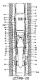
- FIG. 1 The cementing tool of the current disclosure is designated in FIG. 1 with the numeral 10.
- Cementing tool 10 is shown disposed in a well bore 15 connected in a casing 20.
- Casing 20 and well bore 15 define an annulus 21 therebetween.
- Casing 20 may comprise an upper portion 22 and a lower portion 24.
- stage cementing tool 10 may be utilized to cement upper portion 22 of casing 20 in well bore 15.
- cementing tool 10 comprises a housing 26, with a closing sleeve 28 slidably disposed thereabout.
- An operating sleeve 30 is slidably disposed in housing 26 and is detachably connected thereto with a plurality of shear pins 31 or other means known in the art.
- An opening sleeve 32 is slidably received in housing 26 and is detachably connected thereto with shear pins 33 or other means.
- An external stop or retainer 34 is disposed about and connected to housing 26 and may be threadedly connected thereto.
- An inner or internal stop or retainer 36 is disposed in housing 26 and is attached thereto. Retainer 36 may be connected to housing 26 with lock rings 63 received in groove 64 defined in the inner surface of housing 26.
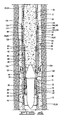
- Housing 26 has upper end 38 which may have an internal thread thereon adapted to connect to the upper portion 22 of casing 20. Housing 26 has lower end 40 which may have external thread or otherwise be adapted to connect to lower portion 24 of casing 20. Housing 26 has an outer or external surface 42 and an inner surface 44 which defines longitudinal central flow passage 46. Housing 26 has at least one and preferably has a plurality of cementing ports 48 defined in a wall 50 thereof. Closing sleeve 28 is shown in FIGS. 2-4 in the open position in which it does not cover cementing ports 48. As will be explained in more detail hereinbelow, when the closing sleeve moves to its closed position, it will cover cementing ports 48 to prevent flow therethrough. Opening sleeve 32 is shown in its closed position in FIGS. 2 and 3 and is shown moved to its open position in FIG. 4 in which cementing port 48 communicates longitudinal central flow passage 46 with the annulus 21.
- Housing 26 has a plurality of slots 52 defined in the wall 50 thereof. Slots 52 have upper end 54 and lower end 56. As will be described in more detail hereinbelow, pins or other locking elements will extend through the slots 52 to mechanically lock or attach operating sleeve 30 to closing sleeve 28. Housing 26 has at least one and preferably a plurality of locking receptacles 58, which may be grooves 58 in the outer surface 42 thereof. Grooves 58 may be referred to herein as locking grooves 58. In the embodiment of FIGS. 2-6 , two grooves 58 may comprise a first or upper locking groove 60 and a second or lower locking groove 62.
- Opening sleeve 32 has upper end 66, lower end 68 and has a seat 70 at upper end 66 thereof. Seat 70 is adapted to receive a plug which as explained in more detail may be a freefall plug 72 which is shown in FIGS. 3-6 . Opening sleeve 32 is shown in the closed position in FIGS. 2 and 3 in which opening sleeve 32 covers cementing ports 48. Opening sleeve 32 is movable in housing 26 from the closed position shown in FIGS. 2 and 3 to the open position shown in FIGS. 4-6 in which the opening sleeve does not cover or prevent flow through cementing ports 48. In the closed position shown in FIGS.
- O-ring seals 74 and 76 disposed about opening sleeve 32 are positioned above and below cementing ports 48 and will sealingly engage inner surface 44 of housing 26. Opening sleeve 32 has a central opening 78 therethrough.
- Operating sleeve 30 has an upper end 80, a lower end 82 and has a seat 84 defined at the upper end 80 thereof.
- Operating sleeve 30 has a central opening 86 therethrough defined by inner surface 88.
- An outer surface 90 of operating sleeve 30 has a groove 91 with an O-ring seal 92 therein to sealingly engage inner surface 44 of housing 26.
- Operating sleeve 30 is initially detachably connected to housing 26 with shear pins 31. When opening sleeve 32 is in its closed position, lower end 82 of operating sleeve 30 may abut upper end 66 of opening sleeve 32.
- a plurality of connecting pins 94 are connected to operating sleeve 30 and will extend through longitudinal slots 52 into a groove 96 defined in inner surface 98 of closing sleeve 28. Operating sleeve 30 is thus mechanically locked to closing sleeve 28 such that longitudinal movement of operating sleeve 30 will cause closing sleeve 28 to move longitudinally along housing 26.
- Closing sleeve 28 has upper end 100 and lower end 102.
- Cementing tool 10 has at least one and preferably a plurality of lock members 104 which may be identified as a first or upper lock member 106 and a second or lower lock member 108.
- lock members 106 and 108 which may be referred to as lock rings 106 and 108, are disposed in first or upper and second or lower retention grooves 110 and 112, respectively, defined in closing sleeve 28.
- Lock rings 106 and 108 are thus movable with, and carried by closing sleeve 28 and are disposed about housing 26.
- Tool 10 has at least one, and as described earlier herein, preferably has a plurality of locking receptacles 58 and in the embodiment shown has first or upper locking groove 60 and second or lower locking groove 62 defined on the outer surface 42 of housing 26.
- cementing tool 10 may be lowered into well bore 15 connected as part of a casing 20.
- Casing 20 is shown in FIG. 1 with the lower portion 24 thereof having been previously cemented by means known in the art.
- a float collar and/or float shoe arrangement may be located at the bottom or lower end of casing 20 and that cement will flow therethrough into the annulus 21 between well bore 15 and casing 20. Opening sleeve 32 will be in its closed position during cementing of lower portion 24 of casing 20, and closing sleeve 28 will be in its open or first position.
- Cement will flow through the bottom of casing 20, and a shutoff plug as is known in the art will pass through casing 20, including cementing tool 10 and will land above the float shoe/collar arrangement on a baffle adapter or other seat.
- the shutoff plug will be pumped through the casing with a displacement fluid.
- FIG. 4 shows opening sleeve 32 moved downwardly to its open position so that cement can be flowed through cementing ports 48 into the annulus 21.
- Plug 114 is displaced through casing 20.
- Plug 114 is preferably a wiper plug that wipes the inside of casing 20 as it is displaced therethrough. As is known in the art, wiper plug 114 will be displaced with a displacement fluid. Increased pressure in the casing will cause shear pins 31 to break and move operating sleeve 30 downwardly, along with closing sleeve 28, and the closing sleeve 28 will move from the open position shown in FIG. 2 to a closed position.
- the closed position as used herein means that closing sleeve 28 has moved downwardly on housing 26 a sufficient amount so that lower seal 124 in groove 126 is positioned below cementing ports 48 while seal 120 in groove 122 is positioned thereabove so that the closing sleeve 28 sealingly engages the housing 26 above and below cementing ports 48 to prevent flow therethrough.
- FIG. 5 shows cementing tool 10 after closing sleeve 28 has been moved such that the second or lower lock ring 108 has engaged upper locking groove 60.
- closing sleeve 28 When closing sleeve 28 reaches such a position, it is locked in the closed position in that lock ring 108 will prevent upward movement of the closing sleeve 28 out of the closed position and thus will prevent leakage through cementing ports 48. While the closing sleeve 28 may still move downwardly, it is nonetheless locked in the closed position since it cannot move upwardly out of the closed position due to the locking engagement of lock ring 108 with locking groove 60.
- closing sleeve 28 has only traveled a portion of its full possible travel distance which is that distance from its position shown in FIG.
- Cementing tool 10 thus has a redundant locking system in that it has a plurality of locking grooves or receptacles adapted to receive a plurality of lock members such that once closing sleeve 28 is in the closed position, the engagement of any lock member 104 with any locking receptacle 58 will lock closing sleeve 28 in a closed position to prevent upward movement thereof and thereby prevent leakage of the treatment fluid that may be pumped through casing 20 to treat zones through cementing ports 48. Leakage through cementing ports can cause degradation of the cement and can cause other concerns such as loss of zonal isolation.
- the locking system is redundant in that there is more than one opportunity for closing sleeve 28 to lock from the initial engagement of second lock ring 108 with first groove 60 to the last engagement which is the engagement of second lock ring 108 with second groove 62.
- First lock ring 106 will engage second locking groove 60 when second lock ring 108 engages second locking groove 62.
- the redundant locking system insures that even if closing sleeve 28 does not complete its full travel, it may still be locked in the closed position. There are a number of reasons why full travel might be prevented including a buildup of debris on housing 26 above outer retainer 34.
- a lock ring was included at or near a lower end of a closing sleeve and was adapted to engage a groove that was in the housing below the cementing ports. The locking groove in the prior art was uncovered and exposed and had a tendency to gather debris which would prevent the lock ring from properly engaging the groove.
- Cementing tool 10 of the current disclosure has locking receptacles 58 that are completely covered by closing sleeve 28 and are protected from the well bore. Thus, debris cannot gather in locking receptacles 58, which are optimally located for proper engagement of lock rings 104.
- Locking receptacles 58 are completely covered when closing sleeve 28 is in the open position, and will be completely covered during the engagement of any of lock rings 104 with any of grooves 58 except for circumferential slots 116 and 118 which provide access to lock rings 58.
- all of the plurality of locking receptacles 58 are completely covered.
- FIGS. 7 and 8 The embodiment of FIGS. 7 and 8 is similar to the embodiment of FIGS. 2-6 and may be referred to as tool 200.
- the details of tool 200 are substantially identical to the details of tool 10, except that in tool 200, the housing, which will be referred to as housing 202 has a plurality of locking receptacles 204, which provide a ratcheting effect.
- Receptacles 204 which may be referred to as locking grooves 204, will receive lock members 106 and 108, so that when either of lock members 106 and 108 are received in any of locking receptacles 204, upward movement of closing sleeve 28 relative to housing 202 is prevented.
- receptacle 7 and 8 has seven receptacles 204, which may include receptacles 206, 208, 210, 212, 214, 216 and 218, but more or less than seven may be included.
- closing sleeve 28 moves to the closed position, and either of lock members 106 and 108 are received in any of the receptacles 204, closing sleeve 28 is locked in the closed position. Closing sleeve 28 is in the closed position in FIG. 8 , but as is apparent, may still move downwardly its full travel, and will still be locked in a closed position.
- FIGS. 9-11 is similar to that of FIGS. 7 and 8 , and will be referred to as tool 300.
- Tool 300 is generally identical to tool 200, except that the closing sleeve has a plurality of spring-loaded, circumferentially spaced lock members 302.
- the closing sleeve in tool 300 may be referred to as closing sleeve 304.
- tool 300 includes the housing 202 with the plurality of receptacles 204. Circumferentially spaced lock members 302, when received in a lock receptacle 204, will prevent closing sleeve 304 from moving upwardly relative to housing 202.
- closing sleeve 304 moves to the closed position, and lock members 302 are received in one of lock receptacles 204, closing sleeve 304 is prevented from upward movement, and is locked in the closed position.
- closing sleeve 304 is in the closed position but has not traveled its full travel distance on housing 202. Closing sleeve 304 may still move downwardly, in which case lock members 302 will engage another of lock receptacles 204, for example, receptacle 216 or 218, and will lock closing sleeve 304 in the closed position. While the embodiment of FIGS.
- Lock members 302 may be for example, Shortie Spring Plungers available from Jergens, Inc., threaded into closing sleeve 304. Lock members 302 may include a threaded body 306, with a plunger 308 biased toward housing 202.
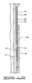
- FIGS. 13 and 14 An additional embodiment of a cementing tool 400 is shown in FIGS. 13 and 14 .
- Tool 400 is similar to tool 10, and its features are generally identical thereto, except that tool 400 has a housing 402 with outer surface 403.
- Housing 402 includes a sleeve 404, that may be referred to as a ratcheting sleeve, affixed to a housing body 405.
- Sleeve 404 may be threaded to housing 402, or connected by other means known in the art.
- Ratcheting sleeve 404 has a plurality of teeth 406 with grooves, or receptacles 408 therebetween.
- Closing sleeve 410 likewise has a plurality of teeth 412, which may be referred to as lock members, with grooves 414 therebetween. Teeth 412 will be received in, and will mate with grooves 408, and will prevent upward movement of closing sleeve 410 relative to housing 402. When closing sleeve 410 moves downward to a closed position, like that in FIG. 14 , the engagement of teeth 412 with grooves 408 defined on outer surface 403 will prevent upward movement, and lock closing sleeve 410 in the closed position. Closing sleeve 410 can move downwardly from the position of FIG. 14 , but cannot move upwardly.
- closing sleeve 410 covers grooves 408 to protect the grooves and to isolate the grooves 408 from the wellbore, thus preventing the buildup of debris therein.
- Grooves 408 that are engaged when closing sleeve 410 is in the closed position are completely covered by the closing sleeve when it is in the open position, and when closing sleeve 410 is in the closed position.
Landscapes
- Geology (AREA)
- Life Sciences & Earth Sciences (AREA)
- Engineering & Computer Science (AREA)
- Mining & Mineral Resources (AREA)
- Environmental & Geological Engineering (AREA)
- Fluid Mechanics (AREA)
- Physics & Mathematics (AREA)
- General Life Sciences & Earth Sciences (AREA)
- Geochemistry & Mineralogy (AREA)
- Earth Drilling (AREA)
- Percussive Tools And Related Accessories (AREA)
- Processing Of Stones Or Stones Resemblance Materials (AREA)
- Quick-Acting Or Multi-Walled Pipe Joints (AREA)
Claims (31)
- Zementierungswerkzeug (10) zur Verwendung in einem Bohrloch (15), das Folgendes umfasst:ein Gehäuse (26), das einen zentralen Durchflusskanal (46) definiert und wenigstens einen Zementierungsanschluss (48) in einer Wand (50) davon umfasst;eine Verschließhülse (28), die um das Gehäuse (26) aufgenommen wird und von einer ersten Position in eine zweite Position beweglich ist, wobei die Verschließhülse (28) den wenigstens einen Zementierungsanschluss (48) in der zweiten Position bedeckt und den wenigstens einen Zementierungsanschluss (48) in der ersten Position nicht bedeckt; undgekennzeichnet durch ein Verriegelungselement (104), das mit der Verschließhülse (28) beweglich ist, wobei das Verriegelungselement (104) mit einer Verriegelungsfassung (58) in der zweiten Position in Eingriff gebracht werden kann, wobei die Verriegelungsfassung (58) von der Verschließhülse (28) bedeckt wird, wenn die Verschließhülse (28) in der ersten Position ist.
- Zementierungswerkzeug (10) nach Anspruch 1, wobei die Verriegelungsfassung (58) oberhalb des wenigstens einen Zementierungsanschlusses (48) positioniert ist.
- Zementierungswerkzeug (10) nach Anspruch 1 oder 2, das mehrere Verriegelungsfassungen (58) umfasst, die auf der Außenfläche des Gehäuses definiert sind.
- Zementierungswerkzeug (10) nach Anspruch 3, wobei die mehreren Verriegelungsfassungen (58) von der Verschließhülse (28) in der ersten Position davon bedeckt werden.
- Zementierungswerkzeug (10) nach Anspruch 3 oder 4, wobei die Verriegelungsfassungen (58) mehrere longitudinal beabstandete Verriegelungsnuten in der Außenfläche des Gehäuses (26) aufweisen, wobei die Verriegelungsnuten von der Verschließhülse (28) in deren erster Position bedeckt werden.
- Zementierungswerkzeug (10) nach Anspruch 5, das mehrere der mit der Verschließhülse beweglichen Verriegelungselemente umfasst, wobei ein Eingriff von beliebigen der Verriegelungselemente mit beliebigen der Verriegelungsnuten nach dem Bewegen der Verschließhülse in die zweite Position eine Aufwärtsbewegung der Verschließhülse relativ zu dem Gehäuse verhindert, um zu verhindern, dass sich die Verschließhülse aus der zweiten Position hinaus bewegt.
- Zementierungswerkzeug (10) nach Anspruch 6, wobei die Verriegelungselemente mehrere mit der Verschließhülse bewegliche Verriegelungsringe umfassen, wobei jeder Verriegelungsring longitudinal vom benachbarten Verriegelungsring beabstandet ist.
- Zementierungswerkzeug (10) nach Anspruch 6 oder 7, wobei sich wenigstens einige der mehreren Verriegelungsnuten oberhalb des wenigstens einen Zementierungsanschlusses befinden.
- Zementierungswerkzeug (10) nach Anspruch 8, wobei sich alle Verriegelungsnuten und Verriegelungsringe oberhalb des Zementierungsanschlusses befinden.
- Zementierungswerkzeug (10) nach einem der Ansprüche 6 bis 9, wobei die Verriegelungselemente mehrere umfangsmäßig beabstandete Verriegelungselemente umfassen, die von der Verschließhülse getragen werden.
- Zementierungswerkzeug (10) nach einem der Ansprüche 1 bis 10, das ferner eine Betriebshülse umfasst, die in dem Gehäuse angeordnet und mit der Verschließhülse verbunden ist, wobei das Gehäuse mehrere darin definierte Verriegelungsfassungen oberhalb des wenigstens einen Zementierungsanschlusses hat.
- Zementierungswerkzeug (10) nach einem der Ansprüche 1 bis 11, das ferner mehrere mit der Verschließhülse bewegliche Verriegelungselemente umfasst, wobei die Verriegelungselemente eine Aufwärtsbewegung der Verschließhülse verhindern, um zu verhindern, dass sich die Verschließhülse aus der geschlossenen Position bewegt, wenn beliebige der Verriegelungselemente in einer der mehreren Verriegelungsfassungen aufgenommen werden, wenn sich die Verschließhülse in die geschlossene Position bewegt hat.
- Zementierungswerkzeug (10) nach Anspruch 12, wobei die Verriegelungsfassungen von der Verschließhülse in der offenen Position der Verschließhülse bedeckt werden.
- Zementierungswerkzeug (10) nach Anspruch 11, 12 oder 13, wobei die Verriegelungselemente Verriegelungsringe aufweisen und die Verriegelungsfassungen Verriegelungsnuten aufweisen.
- Zementierungswerkzeug (10) nach Anspruch 11, 12, 13 oder 14, wobei die Verriegelungselemente longitudinal beabstandete Verriegelungsringe aufweisen und die Verriegelungsfassungen an dem Gehäuse definierte longitudinal beabstandete Verriegelungsnuten aufweisen.
- Zementierungswerkzeug (10) nach Anspruch 14 oder 15, wobei die mehreren Verriegelungsringe von der Verschließhülse getragen werden.
- Zementierungswerkzeug (10) nach einem der Ansprüche 14 bis 16, wobei die Verschließhülse eine volle Wegdistanz entlang dem Gehäuse hat, wobei wenigstens einer der mehreren Verriegelungsringe in eine der mehreren Verriegelungsnuten eingreift, wenn die Verschließhülse in der geschlossenen Position ist, um die Verschließhülse vor der vollen Wegdistanz der Verschließhülse in der geschlossenen Position zu verriegeln.
- Zementierungswerkzeug (10) nach einem der Ansprüche 11 bis 17, wobei die Verriegelungsfassungen Verriegelungsnuten auf der Außenfläche des Gehäuses aufweisen und die Verriegelungselemente Zähne aufweisen, die in die Verriegelungsnuten eingreifen können.
- Zementierungswerkzeug (10) nach Anspruch 18, wobei die Zähne auf der Verschließhülse definiert sind.
- Zementierungswerkzeug (10) nach einem der Ansprüche 11 bis 19, wobei die Verriegelungselemente mehrere Stößel umfassen, die von der Verschließhülse getragen werden und damit beweglich sind.
- Zementierungswerkzeug (10) nach einem vorherigen Anspruch, das ein redundantes Verriegelungssystem umfasst, um zu verhindern, dass sich die Verschließhülse aus der geschlossenen Position bewegt.
- Zementierungswerkzeug (10) nach Anspruch 21, wobei das redundante Verriegelungssystem Folgendes umfasst:mehrere an dem Gehäuse definierte Verriegelungsfassungen; undmehrere mit der Verschließhülse bewegliche Verriegelungselemente, die in den Verriegelungsfassungen aufgenommen werden können.
- Zementierungswerkzeug (10) nach Anspruch 20 oder 21, das ferner Folgendes umfasst:eine in dem Gehäuse angeordnete Betriebshülse, wobei die Verschließhülse um das Gehäuse herum angeordnet ist; undmehrere Verbinder, die durch Schlitze in dem Gehäuse verlaufen, um die Betriebshülse mit der Verschließhülse zu verbinden.
- Zementierungswerkzeug (10) nach Anspruch 22 oder 23, wobei die mehreren Verriegelungsfassungen an der Außenfläche des Gehäuses definiert sind und die Verriegelungselemente von der Verschließhülse getragen werden.
- Zementierungswerkzeug (10) nach Anspruch 22, 23 oder 24, wobei die Verriegelungsfassungen nicht gegenüber dem Bohrloch exponiert werden, wenn die Verschließhülse in der offenen Position ist.
- Zementierungswerkzeug (10) nach Anspruch 25, wobei die Verriegelungsfassungen von der Verschließhülse bedeckt werden, wenn die Verschließhülse in der offenen Position ist.
- Zementierungswerkzeug (10) nach einem der Ansprüche 22 bis 26, wobei die Verriegelungsfassungen an dem Gehäuse definierte Verriegelungsnuten umfassen.
- Zementierungswerkzeug (10) nach einem der Ansprüche 22 bis 27, wobei die Verriegelungselemente von der Verschließhülse getragene Verriegelungsringe umfassen.
- Zementierungswerkzeug (10) nach Anspruch 28, wobei wenigstens einer der mehreren Verriegelungsringe in eine der mehreren Verriegelungsnuten eingreift, um zu verhindern, dass sich die Verschließhülse aus der geschlossenen Position bewegt.
- Zementierungswerkzeug (10) nach Anspruch 28, wobei die Verriegelungsnuten mehrere longitudinal beabstandete Verriegelungsnuten auf einer Außenfläche des Gehäuses aufweisen, wobei die Verriegelungsringe mehrere longitudinal beabstandete Verriegelungsringe umfassen, die von der Verschließhülse getragen werden.
- Zementierungswerkzeug (10) nach einem der Ansprüche 22 bis 30, wobei die Verschließhülse in der geschlossenen Position verriegelt wird, wenn beliebige der mehreren Verriegelungselemente in beliebige der mehreren Verriegelungsfassungen eingreifen, nachdem die Verschließhülse die geschlossene Position erreicht hat.
Applications Claiming Priority (2)
| Application Number | Priority Date | Filing Date | Title |
|---|---|---|---|
| US12/371,374 US8215404B2 (en) | 2009-02-13 | 2009-02-13 | Stage cementing tool |
| PCT/GB2010/000257 WO2010092350A2 (en) | 2009-02-13 | 2010-02-12 | Stage cementing tool |
Publications (2)
| Publication Number | Publication Date |
|---|---|
| EP2396501A2 EP2396501A2 (de) | 2011-12-21 |
| EP2396501B1 true EP2396501B1 (de) | 2014-01-15 |
Family
ID=42470557
Family Applications (1)
| Application Number | Title | Priority Date | Filing Date |
|---|---|---|---|
| EP10703670.9A Not-in-force EP2396501B1 (de) | 2009-02-13 | 2010-02-12 | Werkzeug zur stufenweisen zementierung |
Country Status (9)
| Country | Link |
|---|---|
| US (1) | US8215404B2 (de) |
| EP (1) | EP2396501B1 (de) |
| AU (1) | AU2010212667B2 (de) |
| BR (1) | BRPI1007947B1 (de) |
| CA (1) | CA2751320C (de) |
| MX (1) | MX2011008538A (de) |
| MY (1) | MY153434A (de) |
| SG (1) | SG173640A1 (de) |
| WO (1) | WO2010092350A2 (de) |
Families Citing this family (36)
| Publication number | Priority date | Publication date | Assignee | Title |
|---|---|---|---|---|
| CA2689480C (en) * | 2008-12-31 | 2013-09-03 | Weatherford/Lamb, Inc. | Dual isolation mechanism of cementation port |
| US8267174B2 (en) * | 2009-08-20 | 2012-09-18 | Halliburton Energy Services Inc. | Internal retention mechanism |
| US8839871B2 (en) | 2010-01-15 | 2014-09-23 | Halliburton Energy Services, Inc. | Well tools operable via thermal expansion resulting from reactive materials |
| US8230926B2 (en) * | 2010-03-11 | 2012-07-31 | Halliburton Energy Services Inc. | Multiple stage cementing tool with expandable sealing element |
| US8474533B2 (en) | 2010-12-07 | 2013-07-02 | Halliburton Energy Services, Inc. | Gas generator for pressurizing downhole samples |
| CN102322240A (zh) * | 2011-10-13 | 2012-01-18 | 中国石油集团西部钻探工程有限公司 | 投球液压式分级箍 |
| US8967255B2 (en) | 2011-11-04 | 2015-03-03 | Halliburton Energy Services, Inc. | Subsurface release cementing plug |
| US9260930B2 (en) | 2012-08-30 | 2016-02-16 | Halliburton Energy Services, Inc. | Pressure testing valve and method of using the same |
| US9169705B2 (en) | 2012-10-25 | 2015-10-27 | Halliburton Energy Services, Inc. | Pressure relief-assisted packer |
| US9279310B2 (en) | 2013-01-22 | 2016-03-08 | Halliburton Energy Services, Inc. | Pressure testing valve and method of using the same |
| US9260940B2 (en) | 2013-01-22 | 2016-02-16 | Halliburton Energy Services, Inc. | Pressure testing valve and method of using the same |
| US9587486B2 (en) | 2013-02-28 | 2017-03-07 | Halliburton Energy Services, Inc. | Method and apparatus for magnetic pulse signature actuation |
| US9726009B2 (en) | 2013-03-12 | 2017-08-08 | Halliburton Energy Services, Inc. | Wellbore servicing tools, systems and methods utilizing near-field communication |
| US9284817B2 (en) | 2013-03-14 | 2016-03-15 | Halliburton Energy Services, Inc. | Dual magnetic sensor actuation assembly |
| US9752414B2 (en) | 2013-05-31 | 2017-09-05 | Halliburton Energy Services, Inc. | Wellbore servicing tools, systems and methods utilizing downhole wireless switches |
| US20150075770A1 (en) | 2013-05-31 | 2015-03-19 | Michael Linley Fripp | Wireless activation of wellbore tools |
| AU2014412711B2 (en) | 2014-11-25 | 2018-05-31 | Halliburton Energy Services, Inc. | Wireless activation of wellbore tools |
| US10260313B2 (en) * | 2015-04-01 | 2019-04-16 | Weatherford Technology Holdings, Llc | Metal-to-metal sealing valve with managed flow erosion across sealing member |
| US10890047B2 (en) * | 2016-05-27 | 2021-01-12 | Packers Plus Energy Services Inc. | Wellbore stage tool with redundant closing sleeves |
| US10364644B2 (en) | 2016-09-07 | 2019-07-30 | Saudi Arabian Oil Company | Stage cementing tool |
| WO2020040656A1 (en) | 2018-08-24 | 2020-02-27 | Schlumberger Canada Limited | Systems and methods for horizontal well completions |
| US11391117B2 (en) * | 2019-07-08 | 2022-07-19 | Halliburton Energy Services, Inc. | Annular casing packer collar stage tool for cementing operations |
| WO2021097017A1 (en) | 2019-11-12 | 2021-05-20 | Schlumberger Technology Corporation | Stage cementing collar with cup tool |
| US11280157B2 (en) | 2020-07-17 | 2022-03-22 | Halliburton Energy Services, Inc. | Multi-stage cementing tool |
| US11739611B2 (en) | 2020-12-17 | 2023-08-29 | Halliburton Energy Services, Inc. | Single sleeve, multi-stage cementer |
| US11274519B1 (en) * | 2020-12-30 | 2022-03-15 | Halliburton Energy Services, Inc. | Reverse cementing tool |
| US11566489B2 (en) | 2021-04-29 | 2023-01-31 | Halliburton Energy Services, Inc. | Stage cementer packer |
| US11519242B2 (en) | 2021-04-30 | 2022-12-06 | Halliburton Energy Services, Inc. | Telescopic stage cementer packer |
| US11898416B2 (en) | 2021-05-14 | 2024-02-13 | Halliburton Energy Services, Inc. | Shearable drive pin assembly |
| US11885197B2 (en) | 2021-11-01 | 2024-01-30 | Halliburton Energy Services, Inc. | External sleeve cementer |
| US11965397B2 (en) | 2022-07-20 | 2024-04-23 | Halliburton Energy Services, Inc. | Operating sleeve |
| US11873696B1 (en) | 2022-07-21 | 2024-01-16 | Halliburton Energy Services, Inc. | Stage cementing tool |
| US20240110457A1 (en) * | 2022-09-29 | 2024-04-04 | Halliburton Energy Services, Inc. | Stand alone compression packer |
| US11873698B1 (en) | 2022-09-30 | 2024-01-16 | Halliburton Energy Services, Inc. | Pump-out plug for multi-stage cementer |
| US12241331B1 (en) | 2023-08-29 | 2025-03-04 | Halliburton Energy Services, Inc. | Tight tolerance packer |
| US12241330B1 (en) | 2023-08-29 | 2025-03-04 | Halliburton Energy Services, Inc. | Tight tolerance packer |
Family Cites Families (19)
| Publication number | Priority date | Publication date | Assignee | Title |
|---|---|---|---|---|
| US2925865A (en) | 1956-11-13 | 1960-02-23 | Halliburton Oil Well Cementing | Full flow packer cementing shoe |
| US3768556A (en) | 1972-05-10 | 1973-10-30 | Halliburton Co | Cementing tool |
| US4479545A (en) | 1982-10-27 | 1984-10-30 | Eley Fred N | Well-cementing stage collar |
| US4669541A (en) | 1985-10-04 | 1987-06-02 | Dowell Schlumberger Incorporated | Stage cementing apparatus |
| US4880058A (en) | 1988-05-16 | 1989-11-14 | Lindsey Completion Systems, Inc. | Stage cementing valve |
| US5044444A (en) | 1989-04-28 | 1991-09-03 | Baker Hughes Incorporated | Method and apparatus for chemical treatment of subterranean well bores |
| US5038862A (en) | 1990-04-25 | 1991-08-13 | Halliburton Company | External sleeve cementing tool |
| US5178216A (en) | 1990-04-25 | 1993-01-12 | Halliburton Company | Wedge lock ring |
| US5109925A (en) * | 1991-01-17 | 1992-05-05 | Halliburton Company | Multiple stage inflation packer with secondary opening rupture disc |
| US5277253A (en) | 1992-04-03 | 1994-01-11 | Halliburton Company | Hydraulic set casing packer |
| US5314015A (en) | 1992-07-31 | 1994-05-24 | Halliburton Company | Stage cementer and inflation packer apparatus |
| US5279370A (en) | 1992-08-21 | 1994-01-18 | Halliburton Company | Mechanical cementing packer collar |
| US5526878A (en) | 1995-02-06 | 1996-06-18 | Halliburton Company | Stage cementer with integral inflation packer |
| US5641021A (en) | 1995-11-15 | 1997-06-24 | Halliburton Energy Services | Well casing fill apparatus and method |
| US6651743B2 (en) | 2001-05-24 | 2003-11-25 | Halliburton Energy Services, Inc. | Slim hole stage cementer and method |
| US6622798B1 (en) | 2002-05-08 | 2003-09-23 | Halliburton Energy Services, Inc. | Method and apparatus for maintaining a fluid column in a wellbore annulus |
| US6799635B2 (en) | 2002-08-13 | 2004-10-05 | Halliburton Energy Services, Inc. | Method of cementing a tubular string in a wellbore |
| US7021389B2 (en) * | 2003-02-24 | 2006-04-04 | Bj Services Company | Bi-directional ball seat system and method |
| US20100051276A1 (en) | 2008-09-04 | 2010-03-04 | Rogers Henry E | Stage cementing tool |
-
2009
- 2009-02-13 US US12/371,374 patent/US8215404B2/en active Active
-
2010
- 2010-02-12 BR BRPI1007947A patent/BRPI1007947B1/pt not_active IP Right Cessation
- 2010-02-12 CA CA2751320A patent/CA2751320C/en active Active
- 2010-02-12 MX MX2011008538A patent/MX2011008538A/es active IP Right Grant
- 2010-02-12 AU AU2010212667A patent/AU2010212667B2/en active Active
- 2010-02-12 WO PCT/GB2010/000257 patent/WO2010092350A2/en not_active Ceased
- 2010-02-12 MY MYPI2011003755A patent/MY153434A/en unknown
- 2010-02-12 EP EP10703670.9A patent/EP2396501B1/de not_active Not-in-force
- 2010-02-12 SG SG2011057767A patent/SG173640A1/en unknown
Also Published As
| Publication number | Publication date |
|---|---|
| SG173640A1 (en) | 2011-09-29 |
| WO2010092350A3 (en) | 2010-10-14 |
| WO2010092350A2 (en) | 2010-08-19 |
| US20100206572A1 (en) | 2010-08-19 |
| CA2751320A1 (en) | 2010-08-19 |
| MX2011008538A (es) | 2011-09-01 |
| BRPI1007947B1 (pt) | 2019-12-17 |
| AU2010212667A1 (en) | 2011-09-29 |
| EP2396501A2 (de) | 2011-12-21 |
| CA2751320C (en) | 2013-12-03 |
| US8215404B2 (en) | 2012-07-10 |
| MY153434A (en) | 2015-02-13 |
| AU2010212667B2 (en) | 2014-09-25 |
Similar Documents
| Publication | Publication Date | Title |
|---|---|---|
| EP2396501B1 (de) | Werkzeug zur stufenweisen zementierung | |
| EP2236738B1 (de) | Verfahren und Vorrichtung zur Isolierung und Behandlung von diskreten Bereichen in einem Bohrloch | |
| AU785117B2 (en) | Well completion method and apparatus | |
| US9494008B2 (en) | Segmented seat for wellbore servicing system | |
| US5413180A (en) | One trip backwash/sand control system with extendable washpipe isolation | |
| EP3060744B1 (de) | Refrakturierungsvorrichtung und verfahren für ein bohrloch | |
| EP0774564A2 (de) | Vorrichtung und Verfahren zum Füllen einer Bohrlochverrohrung | |
| EP0728914A2 (de) | Bohrloch-Zementierungswerkzeug | |
| EP2581551A2 (de) | Gashubventil mit Doppfelflusspfad | |
| US20100263873A1 (en) | Method and apparatus for use in selectively fracing a well | |
| MX2012012602A (es) | Aparato y metodo para fracturar un pozo. | |
| CA2798343C (en) | Downhole isolation and depressurization tool | |
| US3223160A (en) | Cementing apparatus | |
| US7401651B2 (en) | Wellbore fluid saver assembly | |
| CA3002949C (en) | Tool assembly with collet and shiftable valve and process for directing fluid flow in a wellbore | |
| US5392850A (en) | System for isolating multiple gravel packed zones in wells | |
| NO342075B1 (no) | Forbikoplingsenhet og fremgangsmåte for innsprøytning av fluid rundt et brønnverktøy | |
| CA2916474A1 (en) | Closable frac sleeve | |
| AU2005311155B2 (en) | Diverter tool | |
| US9915126B2 (en) | High pressure circulating shoe track with redundant pressure isolation feature | |
| CA2521357C (en) | Wellbore fluid saver assembly | |
| CA2862212C (en) | Cementing tool and method for using same | |
| US20170122071A1 (en) | Cementing Tool and Method for Using Same |
Legal Events
| Date | Code | Title | Description |
|---|---|---|---|
| PUAI | Public reference made under article 153(3) epc to a published international application that has entered the european phase |
Free format text: ORIGINAL CODE: 0009012 |
|
| 17P | Request for examination filed |
Effective date: 20110817 |
|
| AK | Designated contracting states |
Kind code of ref document: A2 Designated state(s): AT BE BG CH CY CZ DE DK EE ES FI FR GB GR HR HU IE IS IT LI LT LU LV MC MK MT NL NO PL PT RO SE SI SK SM TR |
|
| DAX | Request for extension of the european patent (deleted) | ||
| 17Q | First examination report despatched |
Effective date: 20121130 |
|
| RIC1 | Information provided on ipc code assigned before grant |
Ipc: E21B 34/14 20060101ALI20130625BHEP Ipc: E21B 33/16 20060101ALI20130625BHEP Ipc: E21B 33/14 20060101AFI20130625BHEP |
|
| GRAP | Despatch of communication of intention to grant a patent |
Free format text: ORIGINAL CODE: EPIDOSNIGR1 |
|
| INTG | Intention to grant announced |
Effective date: 20130808 |
|
| GRAS | Grant fee paid |
Free format text: ORIGINAL CODE: EPIDOSNIGR3 |
|
| GRAA | (expected) grant |
Free format text: ORIGINAL CODE: 0009210 |
|
| AK | Designated contracting states |
Kind code of ref document: B1 Designated state(s): AT BE BG CH CY CZ DE DK EE ES FI FR GB GR HR HU IE IS IT LI LT LU LV MC MK MT NL NO PL PT RO SE SI SK SM TR |
|
| REG | Reference to a national code |
Ref country code: GB Ref legal event code: FG4D Ref country code: CH Ref legal event code: EP |
|
| REG | Reference to a national code |
Ref country code: AT Ref legal event code: REF Ref document number: 649942 Country of ref document: AT Kind code of ref document: T Effective date: 20140215 |
|
| REG | Reference to a national code |
Ref country code: IE Ref legal event code: FG4D |
|
| REG | Reference to a national code |
Ref country code: DE Ref legal event code: R096 Ref document number: 602010013124 Country of ref document: DE Effective date: 20140306 |
|
| REG | Reference to a national code |
Ref country code: NL Ref legal event code: T3 |
|
| REG | Reference to a national code |
Ref country code: AT Ref legal event code: MK05 Ref document number: 649942 Country of ref document: AT Kind code of ref document: T Effective date: 20140115 |
|
| REG | Reference to a national code |
Ref country code: NO Ref legal event code: T2 Effective date: 20140115 |
|
| REG | Reference to a national code |
Ref country code: LT Ref legal event code: MG4D |
|
| PG25 | Lapsed in a contracting state [announced via postgrant information from national office to epo] |
Ref country code: IS Free format text: LAPSE BECAUSE OF FAILURE TO SUBMIT A TRANSLATION OF THE DESCRIPTION OR TO PAY THE FEE WITHIN THE PRESCRIBED TIME-LIMIT Effective date: 20140515 Ref country code: LT Free format text: LAPSE BECAUSE OF FAILURE TO SUBMIT A TRANSLATION OF THE DESCRIPTION OR TO PAY THE FEE WITHIN THE PRESCRIBED TIME-LIMIT Effective date: 20140115 |
|
| PG25 | Lapsed in a contracting state [announced via postgrant information from national office to epo] |
Ref country code: PT Free format text: LAPSE BECAUSE OF FAILURE TO SUBMIT A TRANSLATION OF THE DESCRIPTION OR TO PAY THE FEE WITHIN THE PRESCRIBED TIME-LIMIT Effective date: 20140515 Ref country code: CY Free format text: LAPSE BECAUSE OF FAILURE TO SUBMIT A TRANSLATION OF THE DESCRIPTION OR TO PAY THE FEE WITHIN THE PRESCRIBED TIME-LIMIT Effective date: 20140115 Ref country code: SE Free format text: LAPSE BECAUSE OF FAILURE TO SUBMIT A TRANSLATION OF THE DESCRIPTION OR TO PAY THE FEE WITHIN THE PRESCRIBED TIME-LIMIT Effective date: 20140115 Ref country code: AT Free format text: LAPSE BECAUSE OF FAILURE TO SUBMIT A TRANSLATION OF THE DESCRIPTION OR TO PAY THE FEE WITHIN THE PRESCRIBED TIME-LIMIT Effective date: 20140115 Ref country code: FI Free format text: LAPSE BECAUSE OF FAILURE TO SUBMIT A TRANSLATION OF THE DESCRIPTION OR TO PAY THE FEE WITHIN THE PRESCRIBED TIME-LIMIT Effective date: 20140115 Ref country code: ES Free format text: LAPSE BECAUSE OF FAILURE TO SUBMIT A TRANSLATION OF THE DESCRIPTION OR TO PAY THE FEE WITHIN THE PRESCRIBED TIME-LIMIT Effective date: 20140115 |
|
| PG25 | Lapsed in a contracting state [announced via postgrant information from national office to epo] |
Ref country code: HR Free format text: LAPSE BECAUSE OF FAILURE TO SUBMIT A TRANSLATION OF THE DESCRIPTION OR TO PAY THE FEE WITHIN THE PRESCRIBED TIME-LIMIT Effective date: 20140115 Ref country code: LV Free format text: LAPSE BECAUSE OF FAILURE TO SUBMIT A TRANSLATION OF THE DESCRIPTION OR TO PAY THE FEE WITHIN THE PRESCRIBED TIME-LIMIT Effective date: 20140115 Ref country code: BE Free format text: LAPSE BECAUSE OF FAILURE TO SUBMIT A TRANSLATION OF THE DESCRIPTION OR TO PAY THE FEE WITHIN THE PRESCRIBED TIME-LIMIT Effective date: 20140115 |
|
| REG | Reference to a national code |
Ref country code: CH Ref legal event code: PL |
|
| REG | Reference to a national code |
Ref country code: DE Ref legal event code: R097 Ref document number: 602010013124 Country of ref document: DE |
|
| PG25 | Lapsed in a contracting state [announced via postgrant information from national office to epo] |
Ref country code: CH Free format text: LAPSE BECAUSE OF NON-PAYMENT OF DUE FEES Effective date: 20140228 Ref country code: EE Free format text: LAPSE BECAUSE OF FAILURE TO SUBMIT A TRANSLATION OF THE DESCRIPTION OR TO PAY THE FEE WITHIN THE PRESCRIBED TIME-LIMIT Effective date: 20140115 Ref country code: DK Free format text: LAPSE BECAUSE OF FAILURE TO SUBMIT A TRANSLATION OF THE DESCRIPTION OR TO PAY THE FEE WITHIN THE PRESCRIBED TIME-LIMIT Effective date: 20140115 Ref country code: MC Free format text: LAPSE BECAUSE OF FAILURE TO SUBMIT A TRANSLATION OF THE DESCRIPTION OR TO PAY THE FEE WITHIN THE PRESCRIBED TIME-LIMIT Effective date: 20140115 Ref country code: CZ Free format text: LAPSE BECAUSE OF FAILURE TO SUBMIT A TRANSLATION OF THE DESCRIPTION OR TO PAY THE FEE WITHIN THE PRESCRIBED TIME-LIMIT Effective date: 20140115 Ref country code: RO Free format text: LAPSE BECAUSE OF FAILURE TO SUBMIT A TRANSLATION OF THE DESCRIPTION OR TO PAY THE FEE WITHIN THE PRESCRIBED TIME-LIMIT Effective date: 20140115 Ref country code: LI Free format text: LAPSE BECAUSE OF NON-PAYMENT OF DUE FEES Effective date: 20140228 |
|
| PLBE | No opposition filed within time limit |
Free format text: ORIGINAL CODE: 0009261 |
|
| STAA | Information on the status of an ep patent application or granted ep patent |
Free format text: STATUS: NO OPPOSITION FILED WITHIN TIME LIMIT |
|
| PG25 | Lapsed in a contracting state [announced via postgrant information from national office to epo] |
Ref country code: SK Free format text: LAPSE BECAUSE OF FAILURE TO SUBMIT A TRANSLATION OF THE DESCRIPTION OR TO PAY THE FEE WITHIN THE PRESCRIBED TIME-LIMIT Effective date: 20140115 Ref country code: PL Free format text: LAPSE BECAUSE OF FAILURE TO SUBMIT A TRANSLATION OF THE DESCRIPTION OR TO PAY THE FEE WITHIN THE PRESCRIBED TIME-LIMIT Effective date: 20140115 |
|
| REG | Reference to a national code |
Ref country code: IE Ref legal event code: MM4A |
|
| 26N | No opposition filed |
Effective date: 20141016 |
|
| REG | Reference to a national code |
Ref country code: FR Ref legal event code: PLFP Year of fee payment: 6 |
|
| PG25 | Lapsed in a contracting state [announced via postgrant information from national office to epo] |
Ref country code: IE Free format text: LAPSE BECAUSE OF NON-PAYMENT OF DUE FEES Effective date: 20140212 |
|
| REG | Reference to a national code |
Ref country code: DE Ref legal event code: R097 Ref document number: 602010013124 Country of ref document: DE Effective date: 20141016 |
|
| PG25 | Lapsed in a contracting state [announced via postgrant information from national office to epo] |
Ref country code: SI Free format text: LAPSE BECAUSE OF FAILURE TO SUBMIT A TRANSLATION OF THE DESCRIPTION OR TO PAY THE FEE WITHIN THE PRESCRIBED TIME-LIMIT Effective date: 20140115 |
|
| REG | Reference to a national code |
Ref country code: FR Ref legal event code: PLFP Year of fee payment: 7 |
|
| PG25 | Lapsed in a contracting state [announced via postgrant information from national office to epo] |
Ref country code: MT Free format text: LAPSE BECAUSE OF FAILURE TO SUBMIT A TRANSLATION OF THE DESCRIPTION OR TO PAY THE FEE WITHIN THE PRESCRIBED TIME-LIMIT Effective date: 20140115 |
|
| PG25 | Lapsed in a contracting state [announced via postgrant information from national office to epo] |
Ref country code: SM Free format text: LAPSE BECAUSE OF FAILURE TO SUBMIT A TRANSLATION OF THE DESCRIPTION OR TO PAY THE FEE WITHIN THE PRESCRIBED TIME-LIMIT Effective date: 20140115 |
|
| PG25 | Lapsed in a contracting state [announced via postgrant information from national office to epo] |
Ref country code: BG Free format text: LAPSE BECAUSE OF FAILURE TO SUBMIT A TRANSLATION OF THE DESCRIPTION OR TO PAY THE FEE WITHIN THE PRESCRIBED TIME-LIMIT Effective date: 20140115 Ref country code: GR Free format text: LAPSE BECAUSE OF FAILURE TO SUBMIT A TRANSLATION OF THE DESCRIPTION OR TO PAY THE FEE WITHIN THE PRESCRIBED TIME-LIMIT Effective date: 20140416 Ref country code: IT Free format text: LAPSE BECAUSE OF FAILURE TO SUBMIT A TRANSLATION OF THE DESCRIPTION OR TO PAY THE FEE WITHIN THE PRESCRIBED TIME-LIMIT Effective date: 20140115 |
|
| PG25 | Lapsed in a contracting state [announced via postgrant information from national office to epo] |
Ref country code: LU Free format text: LAPSE BECAUSE OF NON-PAYMENT OF DUE FEES Effective date: 20140212 Ref country code: TR Free format text: LAPSE BECAUSE OF FAILURE TO SUBMIT A TRANSLATION OF THE DESCRIPTION OR TO PAY THE FEE WITHIN THE PRESCRIBED TIME-LIMIT Effective date: 20140115 Ref country code: HU Free format text: LAPSE BECAUSE OF FAILURE TO SUBMIT A TRANSLATION OF THE DESCRIPTION OR TO PAY THE FEE WITHIN THE PRESCRIBED TIME-LIMIT; INVALID AB INITIO Effective date: 20100212 |
|
| REG | Reference to a national code |
Ref country code: FR Ref legal event code: PLFP Year of fee payment: 8 |
|
| REG | Reference to a national code |
Ref country code: FR Ref legal event code: PLFP Year of fee payment: 9 |
|
| PGFP | Annual fee paid to national office [announced via postgrant information from national office to epo] |
Ref country code: NL Payment date: 20180209 Year of fee payment: 9 |
|
| PGFP | Annual fee paid to national office [announced via postgrant information from national office to epo] |
Ref country code: DE Payment date: 20180129 Year of fee payment: 9 |
|
| PGFP | Annual fee paid to national office [announced via postgrant information from national office to epo] |
Ref country code: FR Payment date: 20180129 Year of fee payment: 9 |
|
| PG25 | Lapsed in a contracting state [announced via postgrant information from national office to epo] |
Ref country code: MK Free format text: LAPSE BECAUSE OF FAILURE TO SUBMIT A TRANSLATION OF THE DESCRIPTION OR TO PAY THE FEE WITHIN THE PRESCRIBED TIME-LIMIT Effective date: 20140115 |
|
| REG | Reference to a national code |
Ref country code: DE Ref legal event code: R119 Ref document number: 602010013124 Country of ref document: DE |
|
| REG | Reference to a national code |
Ref country code: NL Ref legal event code: MM Effective date: 20190301 |
|
| PG25 | Lapsed in a contracting state [announced via postgrant information from national office to epo] |
Ref country code: DE Free format text: LAPSE BECAUSE OF NON-PAYMENT OF DUE FEES Effective date: 20190903 Ref country code: NL Free format text: LAPSE BECAUSE OF NON-PAYMENT OF DUE FEES Effective date: 20190301 |
|
| PG25 | Lapsed in a contracting state [announced via postgrant information from national office to epo] |
Ref country code: FR Free format text: LAPSE BECAUSE OF NON-PAYMENT OF DUE FEES Effective date: 20190228 |
|
| PGFP | Annual fee paid to national office [announced via postgrant information from national office to epo] |
Ref country code: GB Payment date: 20211213 Year of fee payment: 13 |
|
| PGFP | Annual fee paid to national office [announced via postgrant information from national office to epo] |
Ref country code: NO Payment date: 20220121 Year of fee payment: 13 |
|
| REG | Reference to a national code |
Ref country code: NO Ref legal event code: MMEP |
|
| GBPC | Gb: european patent ceased through non-payment of renewal fee |
Effective date: 20230212 |
|
| PG25 | Lapsed in a contracting state [announced via postgrant information from national office to epo] |
Ref country code: NO Free format text: LAPSE BECAUSE OF NON-PAYMENT OF DUE FEES Effective date: 20230228 |
|
| PG25 | Lapsed in a contracting state [announced via postgrant information from national office to epo] |
Ref country code: GB Free format text: LAPSE BECAUSE OF NON-PAYMENT OF DUE FEES Effective date: 20230212 |
|
| PG25 | Lapsed in a contracting state [announced via postgrant information from national office to epo] |
Ref country code: GB Free format text: LAPSE BECAUSE OF NON-PAYMENT OF DUE FEES Effective date: 20230212 |