EP3060744B1 - Refrakturierungsvorrichtung und verfahren für ein bohrloch - Google Patents
Refrakturierungsvorrichtung und verfahren für ein bohrloch Download PDFInfo
- Publication number
- EP3060744B1 EP3060744B1 EP14793737.9A EP14793737A EP3060744B1 EP 3060744 B1 EP3060744 B1 EP 3060744B1 EP 14793737 A EP14793737 A EP 14793737A EP 3060744 B1 EP3060744 B1 EP 3060744B1
- Authority
- EP
- European Patent Office
- Prior art keywords
- tubing string
- tools
- wellbore
- split rings
- tool
- Prior art date
- Legal status (The legal status is an assumption and is not a legal conclusion. Google has not performed a legal analysis and makes no representation as to the accuracy of the status listed.)
- Not-in-force
Links
- 238000000034 method Methods 0.000 title claims description 12
- 239000012530 fluid Substances 0.000 claims description 39
- 238000011282 treatment Methods 0.000 claims description 30
- 230000015572 biosynthetic process Effects 0.000 claims description 13
- 238000005086 pumping Methods 0.000 claims description 13
- 238000011268 retreatment Methods 0.000 claims description 11
- 230000014759 maintenance of location Effects 0.000 claims description 5
- 230000008878 coupling Effects 0.000 claims description 4
- 238000010168 coupling process Methods 0.000 claims description 4
- 238000005859 coupling reaction Methods 0.000 claims description 4
- 239000002253 acid Substances 0.000 claims description 2
- 238000007789 sealing Methods 0.000 claims description 2
- 239000002002 slurry Substances 0.000 claims description 2
- -1 proppant Substances 0.000 claims 1
- 208000010392 Bone Fractures Diseases 0.000 description 37
- 206010017076 Fracture Diseases 0.000 description 37
- 238000002955 isolation Methods 0.000 description 34
- 125000006850 spacer group Chemical group 0.000 description 6
- 238000004458 analytical method Methods 0.000 description 5
- 238000004519 manufacturing process Methods 0.000 description 4
- XLYOFNOQVPJJNP-UHFFFAOYSA-N water Substances O XLYOFNOQVPJJNP-UHFFFAOYSA-N 0.000 description 3
- 239000004568 cement Substances 0.000 description 2
- 229920001971 elastomer Polymers 0.000 description 2
- 239000000806 elastomer Substances 0.000 description 2
- 239000007769 metal material Substances 0.000 description 2
- 238000003801 milling Methods 0.000 description 2
- 238000012856 packing Methods 0.000 description 2
- 238000005406 washing Methods 0.000 description 2
- 230000004913 activation Effects 0.000 description 1
- 230000004888 barrier function Effects 0.000 description 1
- 239000002131 composite material Substances 0.000 description 1
- 238000007796 conventional method Methods 0.000 description 1
- 230000000694 effects Effects 0.000 description 1
- 238000002347 injection Methods 0.000 description 1
- 239000007924 injection Substances 0.000 description 1
- 239000000463 material Substances 0.000 description 1
- 230000000717 retained effect Effects 0.000 description 1
- 238000000926 separation method Methods 0.000 description 1
- 239000000243 solution Substances 0.000 description 1
- 239000000126 substance Substances 0.000 description 1
- 238000003466 welding Methods 0.000 description 1
Images




Classifications
-
- E—FIXED CONSTRUCTIONS
- E21—EARTH OR ROCK DRILLING; MINING
- E21B—EARTH OR ROCK DRILLING; OBTAINING OIL, GAS, WATER, SOLUBLE OR MELTABLE MATERIALS OR A SLURRY OF MINERALS FROM WELLS
- E21B43/00—Methods or apparatus for obtaining oil, gas, water, soluble or meltable materials or a slurry of minerals from wells
- E21B43/16—Enhanced recovery methods for obtaining hydrocarbons
-
- E—FIXED CONSTRUCTIONS
- E21—EARTH OR ROCK DRILLING; MINING
- E21B—EARTH OR ROCK DRILLING; OBTAINING OIL, GAS, WATER, SOLUBLE OR MELTABLE MATERIALS OR A SLURRY OF MINERALS FROM WELLS
- E21B33/00—Sealing or packing boreholes or wells
- E21B33/10—Sealing or packing boreholes or wells in the borehole
- E21B33/12—Packers; Plugs
- E21B33/1208—Packers; Plugs characterised by the construction of the sealing or packing means
-
- E—FIXED CONSTRUCTIONS
- E21—EARTH OR ROCK DRILLING; MINING
- E21B—EARTH OR ROCK DRILLING; OBTAINING OIL, GAS, WATER, SOLUBLE OR MELTABLE MATERIALS OR A SLURRY OF MINERALS FROM WELLS
- E21B33/00—Sealing or packing boreholes or wells
- E21B33/10—Sealing or packing boreholes or wells in the borehole
- E21B33/12—Packers; Plugs
- E21B33/124—Units with longitudinally-spaced plugs for isolating the intermediate space
-
- E—FIXED CONSTRUCTIONS
- E21—EARTH OR ROCK DRILLING; MINING
- E21B—EARTH OR ROCK DRILLING; OBTAINING OIL, GAS, WATER, SOLUBLE OR MELTABLE MATERIALS OR A SLURRY OF MINERALS FROM WELLS
- E21B34/00—Valve arrangements for boreholes or wells
- E21B34/06—Valve arrangements for boreholes or wells in wells
- E21B34/14—Valve arrangements for boreholes or wells in wells operated by movement of tools, e.g. sleeve valves operated by pistons or wire line tools
- E21B34/142—Valve arrangements for boreholes or wells in wells operated by movement of tools, e.g. sleeve valves operated by pistons or wire line tools unsupported or free-falling elements, e.g. balls, plugs, darts or pistons
-
- E—FIXED CONSTRUCTIONS
- E21—EARTH OR ROCK DRILLING; MINING
- E21B—EARTH OR ROCK DRILLING; OBTAINING OIL, GAS, WATER, SOLUBLE OR MELTABLE MATERIALS OR A SLURRY OF MINERALS FROM WELLS
- E21B43/00—Methods or apparatus for obtaining oil, gas, water, soluble or meltable materials or a slurry of minerals from wells
- E21B43/11—Perforators; Permeators
- E21B43/114—Perforators using direct fluid action on the wall to be perforated, e.g. abrasive jets
-
- E—FIXED CONSTRUCTIONS
- E21—EARTH OR ROCK DRILLING; MINING
- E21B—EARTH OR ROCK DRILLING; OBTAINING OIL, GAS, WATER, SOLUBLE OR MELTABLE MATERIALS OR A SLURRY OF MINERALS FROM WELLS
- E21B43/00—Methods or apparatus for obtaining oil, gas, water, soluble or meltable materials or a slurry of minerals from wells
- E21B43/14—Obtaining from a multiple-zone well
-
- E—FIXED CONSTRUCTIONS
- E21—EARTH OR ROCK DRILLING; MINING
- E21B—EARTH OR ROCK DRILLING; OBTAINING OIL, GAS, WATER, SOLUBLE OR MELTABLE MATERIALS OR A SLURRY OF MINERALS FROM WELLS
- E21B43/00—Methods or apparatus for obtaining oil, gas, water, soluble or meltable materials or a slurry of minerals from wells
- E21B43/16—Enhanced recovery methods for obtaining hydrocarbons
- E21B43/24—Enhanced recovery methods for obtaining hydrocarbons using heat, e.g. steam injection
-
- E—FIXED CONSTRUCTIONS
- E21—EARTH OR ROCK DRILLING; MINING
- E21B—EARTH OR ROCK DRILLING; OBTAINING OIL, GAS, WATER, SOLUBLE OR MELTABLE MATERIALS OR A SLURRY OF MINERALS FROM WELLS
- E21B43/00—Methods or apparatus for obtaining oil, gas, water, soluble or meltable materials or a slurry of minerals from wells
- E21B43/25—Methods for stimulating production
- E21B43/26—Methods for stimulating production by forming crevices or fractures
-
- E—FIXED CONSTRUCTIONS
- E21—EARTH OR ROCK DRILLING; MINING
- E21B—EARTH OR ROCK DRILLING; OBTAINING OIL, GAS, WATER, SOLUBLE OR MELTABLE MATERIALS OR A SLURRY OF MINERALS FROM WELLS
- E21B43/00—Methods or apparatus for obtaining oil, gas, water, soluble or meltable materials or a slurry of minerals from wells
- E21B43/25—Methods for stimulating production
- E21B43/26—Methods for stimulating production by forming crevices or fractures
- E21B43/267—Methods for stimulating production by forming crevices or fractures reinforcing fractures by propping
-
- E—FIXED CONSTRUCTIONS
- E21—EARTH OR ROCK DRILLING; MINING
- E21B—EARTH OR ROCK DRILLING; OBTAINING OIL, GAS, WATER, SOLUBLE OR MELTABLE MATERIALS OR A SLURRY OF MINERALS FROM WELLS
- E21B2200/00—Special features related to earth drilling for obtaining oil, gas or water
- E21B2200/06—Sleeve valves
Definitions
- a number of techniques can be used to complete a well and prepare it for production.
- a borehole may have casing cemented therein.
- operators perform a plug and perforation operation.
- a jetting tool and a milling tool are run on coil tubing into the cemented casing to clean out residual cement.
- the jetting tool is then used to initially perforate the casing at the toe of the borehole.
- a wireline-deployed perforating gun and a bridge plug are pumped down the casing.
- the bridge plug is set in the casing to isolate the lower zone of the borehole, and the perforating gun perforates the casing.
- the wireline is removed from the borehole, and fracture treatment is pumped down the casing to fracture the zone at the perforations in the casing.
- This operation of pumping down a plug, perforating the casing, and pumping fracture treatment is then repeated multiple times up the borehole until a desired number of zones in the formation have been fractured.
- the bridge plugs can be milled out of the casing using a milling tool.
- a traditional zonal pressure isolation system generally consisting of smaller tubing mounted with packers and fracture sleeves, can be inserted into the existing casing so various zones can be re-fractured.
- Figure 1 shows a wellbore 10 having cemented casing 12 and perforations 14.
- This wellbore 10 may have been initially fractured using plug and perforation operations.
- a wellbore system 20 having an inner tubing string 22 is deployed in the casing 12 from a rig 24.
- the tubing string 22 has various sliding sleeves 30 and packers 40 disposed along its length at particular zones to be re-fractured.
- the packers 40 are set inside the casing 12 to isolate the wellbore annulus 16 into isolated zones.
- the sliding sleeves 30 deployed on the tubing string 22 between the packers 40 can be used to divert treatment fluid to the isolated zones of the surrounding formation through the casing's perforations 14.
- operators rig up fracturing surface equipment 26 for pumping fluid down the tubing string 22.
- operators then deploy specifically sized balls to open the sliding sleeves 30 between the packers 40 and to divert fracture treatment to each of the isolated zones up the wellbore 10.
- the packers 40 used for zonal isolation in the re-fracture operations have elastomeric packing elements, such as swellable elements, cup packers, or hydraulically compressed packing elements.
- a traditional isolation system 20 has a restricted inner dimension because the tubing string 22 must have a dimension capable of fitting in the casing 12. Additionally, the tubing string 22 must be dimensioned so that the sliding sleeves 30 and the packers 40 deployed on the string 22 can operate properly in the available annulus 16 between the tubing string 22 and the existing casing 12.
- the restricted inner dimension of the tubing string 22 caused by these requirements may make the system 20 unacceptable for use at high fracture injection rates.
- One alternative way to perform a re-fracture operation can use a larger internal tubing string that installs in the existing casing 12.
- This larger tubing string allows a secondary plug and perforation operation to be performed in the wellbore 10.
- the annular space between the outer dimension of such a larger internal string and the inner dimension of the existing casing 12 is very limited, and this limited dimension makes isolating the zones along the borehole difficult to achieve.
- the small annular gap might be an application where swellable elastomers could be used. However, there may be no activation fluid available in low fluid level wells for the swellable elastomer to function properly.
- Another alternative way to perform a re-fracture operation can use a large diameter tubing string inserted into the existing casing 12 to tightly fit in the casing 12. It is believed that the tight fit between the inner and outer strings diverts the fracture treatment fluid albeit without a seal.
- One other solution includes mechanically deforming a tubular against the inner dimension of the casing 12 to create the desired zonal isolation, but such systems are very expensive and difficult to implement.
- chemical/cement squeezes have been used for re-fracture operations, but these methods tend be unsatisfactory for pressure integrity and are likewise expensive.
- US 3861465 A describes a selective formation treatment tool which is run into a well and has a retrievable packer which is set in a well casing above perforations in the casing, and a washing or treating fluid tool which has opposed packers which progressively isolate the vertically spaced individual perforated casing sections as the washing or treating tool is progressively moved upwardly to confine the flow of fluid from the tool into the formation through the successive perforations.
- the subject matter of the present disclosure is directed to overcoming, or at least reducing the effects of, one or more of the problems set forth above.
- a re-fracture apparatus uses diversion or isolation tools disposed on a tubing string inserted in a wellbore, which can be an open hole borehole or can be lined with casing.
- This existing casing may have been previously perforated with a plug and perforation operation so that various zones along the wellbore can be hydraulically fractured.
- the tubing string with the tools installs in the borehole or casing.
- the tubing string may include a number of sliding sleeves that can be selectively opened using setting balls or plugs to communicate treatment fluid with the surrounding formation through adjacent perforations.
- the tubing string may be subjected to new plug and perforation operations at selected intervals.
- the tubing string may have an outer dimension that is close to the inner dimension of the borehole or outer casing, which allows the tubing string to convey more fracture fluid during the re-fracture treatment at higher pressures.
- the tools disposed between the sliding sleeves or tubing string intervals each has one or more split rings for sealing (at least partially) against the inner dimension of the borehole or casing to prevent fluid flow out of a selected zone.
- the one or more split rings can be movable ( e . g ., rotatable) on the tubular housing of the tool so that they can readily engage against the inner dimension of the borehole or casing. Being movable, it is possible for the various splits in the split rings to align and misalign relative to one another during use, which will allow at least some fluid flow in the annulus between the tubing string and the borehole or outer casing. The tortuous fluid path created by the split rings, however, inhibits flow in the annulus past the tool's rings so re-fracture treatment can still be concentrated in the zone of interest.
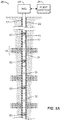
- Figures 2A illustrates wellbore systems 20 according to the present disclosure for re-fracturing zones of a wellbore 10 originally treated through a plug and perforation operation, although other types of wellbores 10 can be subjected to the re-fracturing or retreatment by the disclosed systems 20.
- the wellbore 10 can be an open hole borehole, or as shown, the wellbore 10 can have cemented casing 12 and perforations 14.
- the wellbore system 20 has an inner tubing string 22 deployed in the casing 12 from a rig 24.
- the tubing string 22 has various sliding sleeves 30 disposed along its length at particular zones to be re-fractured.
- the tubing string 22 has blank sections 23 of pipe where new plug and perforation operations can be performed to re-fracture the wellbore 10 at particular zones.
- the tubing string 22 has an increased size so that the inner dimension of the tubing string 22 is larger in relation to the casing 12 and the annulus 16 is narrower. This allows the system 20 to accommodate greater flow rates and higher fracture pressures.
- the tubing string 22 has a number of retreatment/re-fracture isolation tools 50 disposed thereon to isolate the wellbore annulus 16 into the isolated zones.
- the re isolation tools 50 described in Figures 2A-2B may also straddle/isolate existing perforations in the casing and may allow new perforations to be added in various sections of the wellbore.
- the sliding sleeves 30 deployed on the tubing string 22 between the isolation tools 50 can be used to divert treatment fluid to the isolated zone of the surrounding formation through the casing's perforations 14.
- operators rig up fracturing surface equipment 26 for pumping fluid treatment down the tubing string 22.
- operators then deploy specifically sized balls to actuate the sliding sleeves 30 between the isolation tools 50 and to divert fluid treatment to each of the isolated zones up the wellbore 10.
- the system 20 in Figure 2B can use new plug and perforation operations to divert treatment fluid to isolated zones.
- a plug 45 can be deployed in the tubing string 22 to isolate downhole portions of the string 22, and a perforating gun (not shown) can create new perforations 25 in a blank section 23 between the isolation tools 50.
- a perforating gun (not shown) can create new perforations 25 in a blank section 23 between the isolation tools 50.
- operators pump fluid treatment down the tubing string 22 to divert the treatment to the adjacent zone. This new plug and perforation operation can then be repeated up the tubing string 22.
- the isolation tools 50 are configured to at least partially restrict flow in the annulus 16 between the tubing string 22 and the casing 12 so that the fluid treatment communicated out of a particular sliding sleeve 30 or adjacent perforations is primarily diverted to the adjacent isolated zone.
- one configuration of the retreatment/re-fracture isolation tool 50 includes a tubular housing or mandrel 52 with first and second ends 54a-b for coupling to tubing components or other tools ( e . g ., sliding sleeve) on the system's tubing string.
- the housing 52 may alternatively affix on the exterior of a pipe section or mandrel of the tubing string.
- a bore 56 through the tubular housing 52 allows the tool 50 to conduct fluid treatment along the tubing string on which the tool 50 is used.
- the housing's ends 54a-b may be threaded with box and/or pin ends commonly used for coupling to tubing components or other tools.
- the overall length of the tubular housing 52 can depend on the implementation, but may in some cases be about 6-inches.
- the length (L) can be greater to accommodate tongs for installing the tool 50 on tubing during deployment.
- the overall diameter (D) of the tubular housing 52 can also depend on the implementation and would primarily depend on the dimension of the surrounding casing in which the tool 50 is to be used.
- the surrounding casing may be 5-1/2" OD (17 lbs/ft) casing with a maximum inner bore dimension of about 4.976-in. and a minimum inner bore dimension of about 4.819-in.
- the tubular housing 52 for the tool 50 may be similar to 4-1/2" OD (13.5 lbs/ft) flush joint tubing and may have an outer dimension of 4.227 to 4.232-in.
- the outer dimension of the tubular housing 52 can be about 90% of the inner dimension of the surrounding casing. It is expected that for this size of tubing as well as other sizes that the ratio of the housing's outer dimension to the casing's inner dimension can range from about 75 to 90%.
- the split rings 60a-c on the housing 52 may have an uncollapsed dimension of about 5.05-in, essentially making them oversized to an extent relative to the casing's inner dimension. This leaves room for the split rings 60a-c to fit biased in the annular space between the tool's housing 52 and the casing.
- the split rings 60a-c may be collapsible to a drift diameter if necessary.
- the dimensions of the various components can be scaled for any particular implementation as needed.
- Retainers 58a-b, spacers 58c, and the split rings 60a-c are disposed on the tubular housing 52.
- the retainers 58a-b can be affixed toward the ends of the tubular housing 52 using conventional techniques (e . g ., integrated shoulders, fasteners, threads, etc.) so that the split rings 60a-c and the intermediate spacers 58c can be held in place on the tubular housing 52.
- the retainers 58a-b can also help prevent the split rings 60a-c from extruding past them during use.
- the spacers 58c and the split rings 60a-c may be allowed to move ( i.e., rotate) on the tubular housing 52, which can facilitate assembly, deployment, and operation of the tool 50 downhole.
- the split rings 60a-c may be affixed at least partially on the housing 52, it is preferred that they are not secured directly to the housing 52 so they are able to expand and contract properly for the purposes disclosed herein.
- the split rings 60a-c may be allowed to rotate on the housing 52, tabs or other features can be used to interlock or hold the split rings (60a-c) in a desired misaligned arrangement relative to one another so that the splits 62 are opposite each other or stay misaligned.
- one retainer 58a can be an integral part of a first housing portion 52a
- the other retainer 58b can be an integral part of a second housing portion 52b that affixes to the first housing portion 52a in a conventional manner.
- the spacers 58c may have seals 59 (O-rings) on an inner diameter to engage the outside surface of the housing 52 and reduce leakage.
- the spacers 58c may also include lips or pockets 57 inside which the edges of the split rings 60a-c are retained.
- the split rings 60a-c are C-rings having splits or end gaps 62 that allow the rings 60a-c to expand and contract relative to the outer dimension of the tubular housing 52.
- the split 62 is vertical, but other shapes can be used.
- the split 62 may also include a 'Z' shaped separation of the ring 60a-c produced during manufacture.
- the outer dimension for the split rings 60a-c depends on the implementation and would primarily depend on the annular gap between the housing 52 and the surrounding casing in which the tool 50 is to be used.
- the diameter of the split rings 60a-c is configured to engage the inner dimension of the surrounding casing in which the tool 50 is deployed to at least partially seal the annular gap.
- the isolation tool 50 can have three split rings 60a-c, although more or less can be used depending on the treatment (e.g ., fracture) pressures to be used, the flow rates expected, the casing and tubing sizes, and other factors. If possible, one split ring 60 could be used, but it is preferred that the number of split rings 60 is chosen to increase the surface area of potential engagement with the surrounding casing and to complicate the potential tortuous fluid path of any fluid flow past the tool 50 during treatment.
- the isolation tool 50 is not expected to make a perfect pressure seal during use.
- the series of expandable split rings 60a-c installed on the OD of the tubular housing 52 are naturally biased to expand outward to passively engage and contact the ID of the surrounding borehole or casing or open borehole.
- the tubular housing 52, retainers 58a-b, and spacers 58c can be composed of suitable metal materials for downhole use.
- the split rings 60a-c can also be composed of a suitable metal material. Other materials can be used, such as a composite.
- CFD Computational Fluid Dynamics
- the isolation tool 50 can be used for any type of fluid treatment, such as diverting acid, steam, proppant, slurry, or other fluid treatment. Moreover, instead of re-fracture treatment, the isolation tool 50 can be used in a system for performing primary facture treatment in an open or cased hole.
- the disclosed isolation tool 50 produces contact in the ID of the wellbore (i.e., borehole or existing casing) and creates a tortuous fluid path for less bypass flow to pass the tool 50.
- the disclosed tool 50 allows close fitting tubulars to be used in the wellbore ( i.e., borehole or casing) and enables high flow rates while providing a significant barrier against bypass flow.
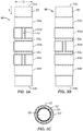
- FIG. 4A-4C the available flow area 70a-c around the isolation tool (50) is conceptually illustrated in three possible configurations as positive spaces 72a-b, 74, and 76 relative to the components of the tool (50), which are not shown.
- the arrangement of the split rings (60a-c) can have a number of configurations relative to one another when disposed on the housing (52). In general, the arrangements break down to two general possibilities-arrangements where the splits (62) of two or more rings (60a-c) are not aligned and an arrangement where the splits (62) of all of the rings (60a-c) are aligned.
- Figure 4A shows the available flow area 70a for the tool (50) when the split rings (60a-c) have their splits (62) unaligned relative to one another.
- the splits (62) in the adjacent split rings (60a-c) are arranged at 180 degrees apart.
- Figure 4B also shows the available flow area 70b for the diversion tool (50) when the split rings (60a-c) have their splits (62) arranged at 180 degrees apart.
- the splits (62) in the split rings (60a-c) are narrower than in Figure 4A , such as when smaller rings are used or the rings are more compressed.
- Figure 4C shows the available flow area 70c for the diversion tool (50) when the split rings (60a-c) have their splits (62) aligned with one another.
- the flow area 70a-c includes an inlet area 72a that would be uphole on the tool (50) in the casing and includes an outlet area 72b that would be downhole on the tool (50) in the casing. Accordingly, the inlet area 72a would be subjected to high pressures during treatment, such as a fracture pressure of as high as about 9000 psi.
- the outlet area 72b would be expected to be at a significantly lower pressure. Any fluid in the annular inlet area 72 around the uphole end of the tool (50) would be able to flow past the first ring (60a) by flowing in the split area 74 of the first split ring (60a).
- the fluid in the intermediate annular area 76 would be able to flow past the second split ring (60b) by flowing in the split area (not visible) of the second split ring (60c). Finally, once past this second split ring (60b), the fluid in the next intermediate annular area 76 would be able to flow past the third split ring (60c) to the outlet area 72b by flowing in the split area 74 of the third split ring (60c).
- the flow in the areas 70a-b in Figures 4A-4B follows a tortuous fluid path due to the misaligned arrangement of the split rings (60a-c). Yet, the flow in the area 70c of Figure 4C follows less of a tortuous fluid path.
- these flow areas 70a-c were analyzed for water flow in CFD analyses to obtain corresponding fluid leakages past the split rings (60a-c) in these example configurations.
- the water pressure at the inlet area 72a was set at 9000 psi
- the pressure at the outlet area 72b was set at zero gauge pressure.
- the water leakage rates through the three geometrical configurations of Figures 4A-4C were found to be 7.8 liters/s, 1.47 liters/s, and 13.33 liters/s, respectively, for the particular dimensions of the tool 50 under analysis.
- isolation tool 50 can be configured to meet the requirements of a particular implementation, providing versatility in the design and use of the disclosed tool 50 in re-fracture treatments.
- the isolation tool 50 has a housing 52 that couples to or is disposed on the tubing string.
- Alternative configurations can be used.
- Figure 5 illustrates an elevational view of one side of another isolation tool 150 for use in the wellbore system.
- the tool 150 uses an existing section of the tubing string or tubular T as the housing for the tool 150.
- First and second retention shoulders 152a-b affix to the exterior of the tubular T. These retention shoulders 152a-b can be held in place on the tubular T in a number of ways, such as using fasteners 154a-b, welding, etc.
- the configuration can use all of the same components and dimensions discussed previously.
- the retentions shoulders 152a-b define the space for split rings 160a-c, retainers 158, etc.
- the tool 150 can be pre-constructed on the tubular T for the tubing string and then deployed with the stands of pipe during operations.
- the tool 150 with its elements can be installed on the tubing string section T during operations, although this may not be preferred.
Landscapes
- Life Sciences & Earth Sciences (AREA)
- Engineering & Computer Science (AREA)
- Geology (AREA)
- Mining & Mineral Resources (AREA)
- Physics & Mathematics (AREA)
- Environmental & Geological Engineering (AREA)
- Fluid Mechanics (AREA)
- General Life Sciences & Earth Sciences (AREA)
- Geochemistry & Mineralogy (AREA)
- Earth Drilling (AREA)
- Branch Pipes, Bends, And The Like (AREA)
Claims (15)
- Verfahren zum Wiederbehandeln einer Formation, die ein Bohrloch (10) hat, wobei das Verfahren Folgendes umfasst:Einsetzen, in dem Bohrloch (10), eines Verrohrungsstrangs (22), der mehrere Werkzeuge (50) hat, die in Abständen an demselben angeordnet sind, wobei jedes Werkzeug (50) mehrere Spaltringe (60a-c) umfasst, die um die Werkzeuge (50) angeordnet sind,Vorspannen der Spaltringe (60a-c) der Werkzeuge (50), um sie passiv mit dem Bohrloch (10) in Eingriff zu bringen,Zugreifen auf den Ringspalt (16) zwischen dem Verrohrungsstrang (22) und dem Bohrloch (10) bei den Abständen zwischen den Werkzeugen (50) undPumpen von Wiederbehandlung in die Formation durch Pumpen der Wiederbehandlung den Verrohrungsstrang (22) hinunter, aus dem Zugang zu dem Ringspalt (16) in den Abständen zwischen den Werkzeugen (50) und wenigstens teilweise abgedichtet in den Abständen durch die in Eingriff gebrachten Spaltringe (60a-c) der Werkzeuge (50).
- Verfahren nach Anspruch 1, wobei das Einsetzen, in dem Bohrloch (10), des Verrohrungsstrangs (22), der die mehreren Werkzeuge (50) hat, die in Abständen an demselben angeordnet sind, das Anordnen der Werkzeuge (50) an dem Verrohrungsstrang (22) durch Verbinden eines Werkzeuggehäuses (52) mit Sektionen des Verrohrungsstrangs (22) umfasst.
- Verfahren nach Anspruch 1, wobei das Pumpen der Wiederbehandlung wenigstens teilweise abgedichtet in den Abständen durch die in Eingriff gebrachten Spaltringe (60a-c) der Werkzeuge (50) das Erzeugen einer kurvenreichen Fluidbahn in dem Ringspalt (16) zwischen Spalten (62) in den Spaltringen (60a-c) umfasst.
- Verfahren nach Anspruch 1, wobei das passive In-Eingriff-Bringen der Spaltringe (60a-c) der Werkzeuge (50) mit dem Bohrloch (10) das Fixieren der Spaltringe (60a-c) in Axialrichtung mit Absätzen (58a-b) an den Werkzeugen (50) umfasst und wahlweise das Halten benachbarter Kanten der Spaltringe (60a-c) mit Ringhaltern (58c), die zwischen den vorgespannten Ringen angeordnet sind, umfasst.
- Verfahren nach Anspruch 1, wobei das Zugreifen auf den Ringspalt (16) zwischen dem Verrohrungsstrang (22) und dem Bohrloch (10) bei den Abständen zwischen den Werkzeugen (50) Folgendes umfasst:Öffnen von Schiebehülsen (30), die an dem Verrohrungsstrang (22) bei den Abständen zwischen den Werkzeugen (50) angeordnet sind und wahlweise selektives Öffnen einer oder mehrerer der Schiebehülsen (30) zu einem Zeitpunkt vor dem Pumpen der Wiederbehandlung in die Formation.
- Verfahren nach Anspruch 1, wobei das Zugreifen auf den Ringspalt (16) zwischen dem Verrohrungsstrang (22) und dem Bohrloch (10) bei den Abständen zwischen den Werkzeugen (50) Folgendes umfasst:Perforieren (25) des Verrohrungsstrangs (22) zwischen den Werkzeugen (50) und wahlweise aufeinanderfolgendes Perforieren (25) entlang des Verrohrungsstrangs (22) bei jedem der Abstände.
- Verfahren nach Anspruch 1, wobei das Pumpen der Wiederbehandlung wenigstens teilweise abgedichtet in den Abständen durch die in Eingriff gebrachten Spaltringe (60a-c) der Werkzeuge (50) das Pumpen mit einer Kapazität, die einen Betrag des Sickerverlusts vorbei an den in Eingriff gebrachten Ringen (60, 160) überschreitet, umfasst.
- Verfahren nach Anspruch 1, wobei das Pumpen der Wiederbehandlung in die Formation das Pumpen einer Fluidbehandlung, die ausgewählt ist aus der Gruppe, die aus Säure, Dampf, Fracking-Fluid, Stützmittel und Schlamm besteht, umfasst.
- Werkzeug (50) für eine Wiederbehandlung einer Formation, die ein Bohrloch (10) hat, unter Verwendung eines Verrohrungsstrangs (22), wobei das Werkzeug (50) Folgendes umfasst:ein Gehäuse (52), das an dem Verrohrungsstrang (22) angeordnet ist, undmehrere Spaltringe (60a-c), die einander benachbart um das Gehäuse (52) entlang einer Länge des Gehäuses (52) angeordnet und nach außen vorgespannt sind, wobei die Spaltringe (60a-c) passive mit dem Bohrloch (10) in Eingriff gebracht werden können und wenigstens teilweise Abstände des Ringspalts (16) zwischen dem Verrohrungsstrang (22) und dem Bohrloch (10) oberhalb und unterhalb der Spaltringe (60a-c) abdichten, undHalteringe, die um das Gehäuse (52) angeordnet sind und in Radialrichtung Kanten der benachbarten Spaltringe (60a-c) in Eingriff nehmen.
- Werkzeug (50) nach Anspruch 9, wobei das Gehäuse (52) ein erstes und ein zweites Ende (54a-b) umfasst, die sich mit Sektionen des Verrohrungsstrangs (22) verbinden.
- Werkzeug (50) nach Anspruch 9, wobei Spalte (62) in den Spaltringen (60a-c) eine kurvenreiche Fluidbahn in dem Ringspalt (16) definieren.
- Werkzeug (50) nach Anspruch 9, wobei die Spaltringe (60a-c) einen nicht zusammengeschobenen Durchmesser umfassen, der wenigstens größer ist als eine innere Abmessung des Bohrlochs (10).
- Werkzeug (50) nach Anspruch 9, wobei die Halteringe, die um das Gehäuse (52) angeordnet sind, obere und untere Halter (58a-b) umfassen, die an einem Äußeren desselben angeordnet sind und eine axiale Bewegung der Spaltringe (60a-c) entlang der Länge des Gehäuses (52) einschränken.
- Werkzeug (50) nach einem der Ansprüche 9 bis 13, wobei wenigstens zwei der Spaltringe (60a-c) Spalte haben, die in Längsrichtung nicht miteinander fluchten.
- Vorrichtung (20) für die Wiederbehandlung einer Formation, die ein Bohrloch (10) hat, wobei die Vorrichtung mehrere Werkzeuge nach einem der Ansprüche 9 bis 14 umfasst.
Applications Claiming Priority (2)
| Application Number | Priority Date | Filing Date | Title |
|---|---|---|---|
| US201361895858P | 2013-10-25 | 2013-10-25 | |
| PCT/US2014/062127 WO2015061655A2 (en) | 2013-10-25 | 2014-10-24 | Re-fracture apparatus and method for wellbore |
Publications (2)
| Publication Number | Publication Date |
|---|---|
| EP3060744A2 EP3060744A2 (de) | 2016-08-31 |
| EP3060744B1 true EP3060744B1 (de) | 2018-04-11 |
Family
ID=51862598
Family Applications (1)
| Application Number | Title | Priority Date | Filing Date |
|---|---|---|---|
| EP14793737.9A Not-in-force EP3060744B1 (de) | 2013-10-25 | 2014-10-24 | Refrakturierungsvorrichtung und verfahren für ein bohrloch |
Country Status (5)
| Country | Link |
|---|---|
| US (1) | US9765605B2 (de) |
| EP (1) | EP3060744B1 (de) |
| AU (1) | AU2014339969B2 (de) |
| CA (1) | CA2936144C (de) |
| WO (1) | WO2015061655A2 (de) |
Families Citing this family (27)
| Publication number | Priority date | Publication date | Assignee | Title |
|---|---|---|---|---|
| US10808497B2 (en) | 2011-05-11 | 2020-10-20 | Schlumberger Technology Corporation | Methods of zonal isolation and treatment diversion |
| US10738577B2 (en) | 2014-07-22 | 2020-08-11 | Schlumberger Technology Corporation | Methods and cables for use in fracturing zones in a well |
| US10001613B2 (en) | 2014-07-22 | 2018-06-19 | Schlumberger Technology Corporation | Methods and cables for use in fracturing zones in a well |
| NO342718B1 (no) * | 2014-08-19 | 2018-07-30 | Frac Tech As | Ventilsystem for et produksjonsrør i en brønn |
| US20160333680A1 (en) * | 2015-05-12 | 2016-11-17 | Schlumberger Technology Corporation | Well re-fracturing method |
| WO2017147100A1 (en) * | 2016-02-24 | 2017-08-31 | Klx Energy Services Llc | Wellbore flow diversion tool utilizing tortuous paths in bow spring centralizer structure |
| US10280698B2 (en) | 2016-10-24 | 2019-05-07 | General Electric Company | Well restimulation downhole assembly |
| US10571027B2 (en) | 2017-06-09 | 2020-02-25 | Gryphon Oilfield Solutions, Llc | Metal ring seal and improved profile selective system for downhole tools |
| US11912572B1 (en) | 2023-03-03 | 2024-02-27 | EnhancedGEO Holdings, LLC | Thermochemical reactions using geothermal energy |
| US11841172B2 (en) | 2022-02-28 | 2023-12-12 | EnhancedGEO Holdings, LLC | Geothermal power from superhot geothermal fluid and magma reservoirs |
| US12055131B2 (en) | 2022-02-28 | 2024-08-06 | EnhancedGEO Holdings, LLC | Geothermal power from superhot geothermal fluid and magma reservoirs |
| US12326278B2 (en) | 2022-02-28 | 2025-06-10 | EnhancedGEO Holdings, LLC | Geothermal power from superhot geothermal fluid and magma reservoirs |
| TW202336345A (zh) * | 2022-02-28 | 2023-09-16 | 美商英漢Geo控股責任有限公司 | 來自過熱地熱流體及岩漿庫之地熱電力 |
| US11905797B2 (en) | 2022-05-01 | 2024-02-20 | EnhancedGEO Holdings, LLC | Wellbore for extracting heat from magma bodies |
| US11918967B1 (en) | 2022-09-09 | 2024-03-05 | EnhancedGEO Holdings, LLC | System and method for magma-driven thermochemical processes |
| US12504203B2 (en) | 2023-02-10 | 2025-12-23 | EnhancedGEO Holdings, LLC | Reverse-flow magma-based geothermal generation |
| US11913679B1 (en) | 2023-03-02 | 2024-02-27 | EnhancedGEO Holdings, LLC | Geothermal systems and methods with an underground magma chamber |
| US11912573B1 (en) | 2023-03-03 | 2024-02-27 | EnhancedGEO Holdings, LLC | Molten-salt mediated thermochemical reactions using geothermal energy |
| US11897828B1 (en) | 2023-03-03 | 2024-02-13 | EnhancedGEO, Holdings, LLC | Thermochemical reactions using geothermal energy |
| US12297711B2 (en) | 2023-04-28 | 2025-05-13 | EnhancedGEO Holdings, LLC | Casing a wellbore in magma |
| US12060765B1 (en) | 2023-07-27 | 2024-08-13 | EnhancedGEO Holdings, LLC | Float shoe for a magma wellbore |
| US12540514B2 (en) | 2023-07-27 | 2026-02-03 | EnhancedGEO Holdings, LLC | Tubing anchor for a magma wellbore |
| US12570826B2 (en) | 2023-08-14 | 2026-03-10 | EnhancedGEO Holdings, LLC | Thermal depolymerization and monomer repurposing using geothermal energy |
| US12522710B2 (en) | 2023-08-14 | 2026-01-13 | EnhancedGEO Holdings, LLC | Flow through process for thermal depolymerization and monomer repurposing using geothermal energy |
| US12180820B1 (en) | 2023-09-27 | 2024-12-31 | EnhancedGEO Holdings, LLC | Drilling a wellbore into a magma reservoir |
| US12291965B2 (en) | 2023-09-08 | 2025-05-06 | EnhancedGEO Holdings, LLC | Detecting entry into and drilling through a magma reservoir |
| US11905814B1 (en) | 2023-09-27 | 2024-02-20 | EnhancedGEO Holdings, LLC | Detecting entry into and drilling through a magma/rock transition zone |
Family Cites Families (9)
| Publication number | Priority date | Publication date | Assignee | Title |
|---|---|---|---|---|
| US2761748A (en) * | 1953-02-02 | 1956-09-04 | Ramsey Corp | Sealing ring assembly |
| US3396798A (en) * | 1966-11-14 | 1968-08-13 | Burns Tool Co | Circulating washer tool |
| US3861465A (en) * | 1972-08-28 | 1975-01-21 | Baker Oil Tools Inc | Method of selective formation treatment |
| US5161612A (en) * | 1991-09-16 | 1992-11-10 | Stafford Lawrence R | Well casing wash assembly |
| US5303774A (en) | 1992-12-11 | 1994-04-19 | Duhn Oil Tool, Inc. | Ring seal packer |
| US5803178A (en) * | 1996-09-13 | 1998-09-08 | Union Oil Company Of California | Downwell isolator |
| US6315041B1 (en) | 1999-04-15 | 2001-11-13 | Stephen L. Carlisle | Multi-zone isolation tool and method of stimulating and testing a subterranean well |
| US8505639B2 (en) * | 2010-04-02 | 2013-08-13 | Weatherford/Lamb, Inc. | Indexing sleeve for single-trip, multi-stage fracing |
| DK2436874T3 (da) * | 2010-09-30 | 2013-10-07 | Welltec As | Borerør |
-
2014
- 2014-10-24 EP EP14793737.9A patent/EP3060744B1/de not_active Not-in-force
- 2014-10-24 CA CA2936144A patent/CA2936144C/en not_active Expired - Fee Related
- 2014-10-24 WO PCT/US2014/062127 patent/WO2015061655A2/en not_active Ceased
- 2014-10-24 AU AU2014339969A patent/AU2014339969B2/en not_active Ceased
- 2014-10-24 US US14/522,960 patent/US9765605B2/en not_active Expired - Fee Related
Also Published As
| Publication number | Publication date |
|---|---|
| WO2015061655A3 (en) | 2015-07-23 |
| CA2936144A1 (en) | 2015-04-30 |
| EP3060744A2 (de) | 2016-08-31 |
| AU2014339969B2 (en) | 2017-05-25 |
| US20150114639A1 (en) | 2015-04-30 |
| WO2015061655A2 (en) | 2015-04-30 |
| US9765605B2 (en) | 2017-09-19 |
| CA2936144C (en) | 2018-11-06 |
Similar Documents
| Publication | Publication Date | Title |
|---|---|---|
| EP3060744B1 (de) | Refrakturierungsvorrichtung und verfahren für ein bohrloch | |
| AU2014339969A1 (en) | Re-fracture apparatus and method for wellbore | |
| US10480276B2 (en) | Wellbore plug isolation system and method | |
| AU2014391093B2 (en) | Multi-zone actuation system using wellbore darts | |
| CN110268133B (zh) | 以可流动的方式安装用于砂控的砂筛的压裂井和完井的系统和相关方法 | |
| EP2932022B1 (de) | Schiebehülse mit kontraktierendem doppelsegmentiertem kugelsitz | |
| AU2016315921B2 (en) | Three position interventionless treatment and production valve assembly | |
| US8371386B2 (en) | Rotatable valve for downhole completions and method of using same | |
| RU2599748C2 (ru) | Забойная система клапанов с гильзовым затвором и способ ее применения | |
| US10927644B2 (en) | Single size actuator for multiple sliding sleeves | |
| US10947815B2 (en) | Tool assembly with collet and shiftable valve and process for directing fluid flow in a wellbore | |
| US11808106B2 (en) | Multi-stage hydraulic fracturing tool and system | |
| AU2017382513B2 (en) | Well tool having a removable collar for allowing production fluid flow | |
| AU2017395716B2 (en) | One trip treating tool for a resource exploration system and method of treating a formation | |
| CA3036420A1 (en) | Shiftable tubular valve assembly and process for directing fluid flow in a wellbore |
Legal Events
| Date | Code | Title | Description |
|---|---|---|---|
| PUAI | Public reference made under article 153(3) epc to a published international application that has entered the european phase |
Free format text: ORIGINAL CODE: 0009012 |
|
| 17P | Request for examination filed |
Effective date: 20160422 |
|
| AK | Designated contracting states |
Kind code of ref document: A2 Designated state(s): AL AT BE BG CH CY CZ DE DK EE ES FI FR GB GR HR HU IE IS IT LI LT LU LV MC MK MT NL NO PL PT RO RS SE SI SK SM TR |
|
| AX | Request for extension of the european patent |
Extension state: BA ME |
|
| DAX | Request for extension of the european patent (deleted) | ||
| RAP1 | Party data changed (applicant data changed or rights of an application transferred) |
Owner name: WEATHERFORD TECHNOLOGY HOLDINGS, LLC |
|
| STAA | Information on the status of an ep patent application or granted ep patent |
Free format text: STATUS: EXAMINATION IS IN PROGRESS |
|
| 17Q | First examination report despatched |
Effective date: 20170413 |
|
| GRAP | Despatch of communication of intention to grant a patent |
Free format text: ORIGINAL CODE: EPIDOSNIGR1 |
|
| STAA | Information on the status of an ep patent application or granted ep patent |
Free format text: STATUS: GRANT OF PATENT IS INTENDED |
|
| INTG | Intention to grant announced |
Effective date: 20171027 |
|
| GRAS | Grant fee paid |
Free format text: ORIGINAL CODE: EPIDOSNIGR3 |
|
| GRAA | (expected) grant |
Free format text: ORIGINAL CODE: 0009210 |
|
| STAA | Information on the status of an ep patent application or granted ep patent |
Free format text: STATUS: THE PATENT HAS BEEN GRANTED |
|
| AK | Designated contracting states |
Kind code of ref document: B1 Designated state(s): AL AT BE BG CH CY CZ DE DK EE ES FI FR GB GR HR HU IE IS IT LI LT LU LV MC MK MT NL NO PL PT RO RS SE SI SK SM TR |
|
| REG | Reference to a national code |
Ref country code: GB Ref legal event code: FG4D |
|
| REG | Reference to a national code |
Ref country code: CH Ref legal event code: EP |
|
| REG | Reference to a national code |
Ref country code: AT Ref legal event code: REF Ref document number: 988230 Country of ref document: AT Kind code of ref document: T Effective date: 20180415 |
|
| REG | Reference to a national code |
Ref country code: IE Ref legal event code: FG4D |
|
| REG | Reference to a national code |
Ref country code: DE Ref legal event code: R096 Ref document number: 602014023837 Country of ref document: DE |
|
| REG | Reference to a national code |
Ref country code: NL Ref legal event code: MP Effective date: 20180411 |
|
| REG | Reference to a national code |
Ref country code: NO Ref legal event code: T2 Effective date: 20180411 Ref country code: LT Ref legal event code: MG4D |
|
| PG25 | Lapsed in a contracting state [announced via postgrant information from national office to epo] |
Ref country code: NL Free format text: LAPSE BECAUSE OF FAILURE TO SUBMIT A TRANSLATION OF THE DESCRIPTION OR TO PAY THE FEE WITHIN THE PRESCRIBED TIME-LIMIT Effective date: 20180411 |
|
| PG25 | Lapsed in a contracting state [announced via postgrant information from national office to epo] |
Ref country code: AL Free format text: LAPSE BECAUSE OF FAILURE TO SUBMIT A TRANSLATION OF THE DESCRIPTION OR TO PAY THE FEE WITHIN THE PRESCRIBED TIME-LIMIT Effective date: 20180411 Ref country code: ES Free format text: LAPSE BECAUSE OF FAILURE TO SUBMIT A TRANSLATION OF THE DESCRIPTION OR TO PAY THE FEE WITHIN THE PRESCRIBED TIME-LIMIT Effective date: 20180411 Ref country code: SE Free format text: LAPSE BECAUSE OF FAILURE TO SUBMIT A TRANSLATION OF THE DESCRIPTION OR TO PAY THE FEE WITHIN THE PRESCRIBED TIME-LIMIT Effective date: 20180411 Ref country code: PL Free format text: LAPSE BECAUSE OF FAILURE TO SUBMIT A TRANSLATION OF THE DESCRIPTION OR TO PAY THE FEE WITHIN THE PRESCRIBED TIME-LIMIT Effective date: 20180411 Ref country code: FI Free format text: LAPSE BECAUSE OF FAILURE TO SUBMIT A TRANSLATION OF THE DESCRIPTION OR TO PAY THE FEE WITHIN THE PRESCRIBED TIME-LIMIT Effective date: 20180411 Ref country code: LT Free format text: LAPSE BECAUSE OF FAILURE TO SUBMIT A TRANSLATION OF THE DESCRIPTION OR TO PAY THE FEE WITHIN THE PRESCRIBED TIME-LIMIT Effective date: 20180411 Ref country code: BG Free format text: LAPSE BECAUSE OF FAILURE TO SUBMIT A TRANSLATION OF THE DESCRIPTION OR TO PAY THE FEE WITHIN THE PRESCRIBED TIME-LIMIT Effective date: 20180711 |
|
| PG25 | Lapsed in a contracting state [announced via postgrant information from national office to epo] |
Ref country code: RS Free format text: LAPSE BECAUSE OF FAILURE TO SUBMIT A TRANSLATION OF THE DESCRIPTION OR TO PAY THE FEE WITHIN THE PRESCRIBED TIME-LIMIT Effective date: 20180411 Ref country code: HR Free format text: LAPSE BECAUSE OF FAILURE TO SUBMIT A TRANSLATION OF THE DESCRIPTION OR TO PAY THE FEE WITHIN THE PRESCRIBED TIME-LIMIT Effective date: 20180411 Ref country code: LV Free format text: LAPSE BECAUSE OF FAILURE TO SUBMIT A TRANSLATION OF THE DESCRIPTION OR TO PAY THE FEE WITHIN THE PRESCRIBED TIME-LIMIT Effective date: 20180411 Ref country code: GR Free format text: LAPSE BECAUSE OF FAILURE TO SUBMIT A TRANSLATION OF THE DESCRIPTION OR TO PAY THE FEE WITHIN THE PRESCRIBED TIME-LIMIT Effective date: 20180712 |
|
| REG | Reference to a national code |
Ref country code: AT Ref legal event code: MK05 Ref document number: 988230 Country of ref document: AT Kind code of ref document: T Effective date: 20180411 |
|
| PG25 | Lapsed in a contracting state [announced via postgrant information from national office to epo] |
Ref country code: PT Free format text: LAPSE BECAUSE OF FAILURE TO SUBMIT A TRANSLATION OF THE DESCRIPTION OR TO PAY THE FEE WITHIN THE PRESCRIBED TIME-LIMIT Effective date: 20180813 |
|
| REG | Reference to a national code |
Ref country code: DE Ref legal event code: R097 Ref document number: 602014023837 Country of ref document: DE |
|
| PG25 | Lapsed in a contracting state [announced via postgrant information from national office to epo] |
Ref country code: RO Free format text: LAPSE BECAUSE OF FAILURE TO SUBMIT A TRANSLATION OF THE DESCRIPTION OR TO PAY THE FEE WITHIN THE PRESCRIBED TIME-LIMIT Effective date: 20180411 Ref country code: CZ Free format text: LAPSE BECAUSE OF FAILURE TO SUBMIT A TRANSLATION OF THE DESCRIPTION OR TO PAY THE FEE WITHIN THE PRESCRIBED TIME-LIMIT Effective date: 20180411 Ref country code: SK Free format text: LAPSE BECAUSE OF FAILURE TO SUBMIT A TRANSLATION OF THE DESCRIPTION OR TO PAY THE FEE WITHIN THE PRESCRIBED TIME-LIMIT Effective date: 20180411 Ref country code: EE Free format text: LAPSE BECAUSE OF FAILURE TO SUBMIT A TRANSLATION OF THE DESCRIPTION OR TO PAY THE FEE WITHIN THE PRESCRIBED TIME-LIMIT Effective date: 20180411 Ref country code: DK Free format text: LAPSE BECAUSE OF FAILURE TO SUBMIT A TRANSLATION OF THE DESCRIPTION OR TO PAY THE FEE WITHIN THE PRESCRIBED TIME-LIMIT Effective date: 20180411 Ref country code: AT Free format text: LAPSE BECAUSE OF FAILURE TO SUBMIT A TRANSLATION OF THE DESCRIPTION OR TO PAY THE FEE WITHIN THE PRESCRIBED TIME-LIMIT Effective date: 20180411 |
|
| PLBE | No opposition filed within time limit |
Free format text: ORIGINAL CODE: 0009261 |
|
| STAA | Information on the status of an ep patent application or granted ep patent |
Free format text: STATUS: NO OPPOSITION FILED WITHIN TIME LIMIT |
|
| PG25 | Lapsed in a contracting state [announced via postgrant information from national office to epo] |
Ref country code: IT Free format text: LAPSE BECAUSE OF FAILURE TO SUBMIT A TRANSLATION OF THE DESCRIPTION OR TO PAY THE FEE WITHIN THE PRESCRIBED TIME-LIMIT Effective date: 20180411 Ref country code: SM Free format text: LAPSE BECAUSE OF FAILURE TO SUBMIT A TRANSLATION OF THE DESCRIPTION OR TO PAY THE FEE WITHIN THE PRESCRIBED TIME-LIMIT Effective date: 20180411 |
|
| 26N | No opposition filed |
Effective date: 20190114 |
|
| REG | Reference to a national code |
Ref country code: DE Ref legal event code: R119 Ref document number: 602014023837 Country of ref document: DE |
|
| PG25 | Lapsed in a contracting state [announced via postgrant information from national office to epo] |
Ref country code: SI Free format text: LAPSE BECAUSE OF FAILURE TO SUBMIT A TRANSLATION OF THE DESCRIPTION OR TO PAY THE FEE WITHIN THE PRESCRIBED TIME-LIMIT Effective date: 20180411 |
|
| REG | Reference to a national code |
Ref country code: CH Ref legal event code: PL |
|
| REG | Reference to a national code |
Ref country code: BE Ref legal event code: MM Effective date: 20181031 |
|
| PG25 | Lapsed in a contracting state [announced via postgrant information from national office to epo] |
Ref country code: MC Free format text: LAPSE BECAUSE OF FAILURE TO SUBMIT A TRANSLATION OF THE DESCRIPTION OR TO PAY THE FEE WITHIN THE PRESCRIBED TIME-LIMIT Effective date: 20180411 Ref country code: LU Free format text: LAPSE BECAUSE OF NON-PAYMENT OF DUE FEES Effective date: 20181024 |
|
| REG | Reference to a national code |
Ref country code: IE Ref legal event code: MM4A |
|
| PG25 | Lapsed in a contracting state [announced via postgrant information from national office to epo] |
Ref country code: DE Free format text: LAPSE BECAUSE OF NON-PAYMENT OF DUE FEES Effective date: 20190501 |
|
| PG25 | Lapsed in a contracting state [announced via postgrant information from national office to epo] |
Ref country code: BE Free format text: LAPSE BECAUSE OF NON-PAYMENT OF DUE FEES Effective date: 20181031 Ref country code: CH Free format text: LAPSE BECAUSE OF NON-PAYMENT OF DUE FEES Effective date: 20181031 Ref country code: LI Free format text: LAPSE BECAUSE OF NON-PAYMENT OF DUE FEES Effective date: 20181031 Ref country code: FR Free format text: LAPSE BECAUSE OF NON-PAYMENT OF DUE FEES Effective date: 20181031 |
|
| PG25 | Lapsed in a contracting state [announced via postgrant information from national office to epo] |
Ref country code: IE Free format text: LAPSE BECAUSE OF NON-PAYMENT OF DUE FEES Effective date: 20181024 |
|
| PG25 | Lapsed in a contracting state [announced via postgrant information from national office to epo] |
Ref country code: MT Free format text: LAPSE BECAUSE OF NON-PAYMENT OF DUE FEES Effective date: 20181024 |
|
| PGFP | Annual fee paid to national office [announced via postgrant information from national office to epo] |
Ref country code: NO Payment date: 20191009 Year of fee payment: 6 |
|
| PG25 | Lapsed in a contracting state [announced via postgrant information from national office to epo] |
Ref country code: TR Free format text: LAPSE BECAUSE OF FAILURE TO SUBMIT A TRANSLATION OF THE DESCRIPTION OR TO PAY THE FEE WITHIN THE PRESCRIBED TIME-LIMIT Effective date: 20180411 |
|
| PGFP | Annual fee paid to national office [announced via postgrant information from national office to epo] |
Ref country code: GB Payment date: 20191001 Year of fee payment: 6 |
|
| PG25 | Lapsed in a contracting state [announced via postgrant information from national office to epo] |
Ref country code: CY Free format text: LAPSE BECAUSE OF FAILURE TO SUBMIT A TRANSLATION OF THE DESCRIPTION OR TO PAY THE FEE WITHIN THE PRESCRIBED TIME-LIMIT Effective date: 20180411 Ref country code: HU Free format text: LAPSE BECAUSE OF FAILURE TO SUBMIT A TRANSLATION OF THE DESCRIPTION OR TO PAY THE FEE WITHIN THE PRESCRIBED TIME-LIMIT; INVALID AB INITIO Effective date: 20141024 Ref country code: MK Free format text: LAPSE BECAUSE OF NON-PAYMENT OF DUE FEES Effective date: 20180411 |
|
| PG25 | Lapsed in a contracting state [announced via postgrant information from national office to epo] |
Ref country code: IS Free format text: LAPSE BECAUSE OF FAILURE TO SUBMIT A TRANSLATION OF THE DESCRIPTION OR TO PAY THE FEE WITHIN THE PRESCRIBED TIME-LIMIT Effective date: 20180811 |
|
| REG | Reference to a national code |
Ref country code: GB Ref legal event code: 732E Free format text: REGISTERED BETWEEN 20200813 AND 20200819 |
|
| REG | Reference to a national code |
Ref country code: GB Ref legal event code: 732E Free format text: REGISTERED BETWEEN 20201126 AND 20201202 |
|
| REG | Reference to a national code |
Ref country code: NO Ref legal event code: MMEP |
|
| GBPC | Gb: european patent ceased through non-payment of renewal fee |
Effective date: 20201024 |
|
| PG25 | Lapsed in a contracting state [announced via postgrant information from national office to epo] |
Ref country code: NO Free format text: LAPSE BECAUSE OF NON-PAYMENT OF DUE FEES Effective date: 20201031 |
|
| PG25 | Lapsed in a contracting state [announced via postgrant information from national office to epo] |
Ref country code: GB Free format text: LAPSE BECAUSE OF NON-PAYMENT OF DUE FEES Effective date: 20201024 |