EP0774564A2 - Vorrichtung und Verfahren zum Füllen einer Bohrlochverrohrung - Google Patents
Vorrichtung und Verfahren zum Füllen einer Bohrlochverrohrung Download PDFInfo
- Publication number
- EP0774564A2 EP0774564A2 EP96308287A EP96308287A EP0774564A2 EP 0774564 A2 EP0774564 A2 EP 0774564A2 EP 96308287 A EP96308287 A EP 96308287A EP 96308287 A EP96308287 A EP 96308287A EP 0774564 A2 EP0774564 A2 EP 0774564A2
- Authority
- EP
- European Patent Office
- Prior art keywords
- closing sleeve
- well bore
- casing string
- casing
- plug
- Prior art date
- Legal status (The legal status is an assumption and is not a legal conclusion. Google has not performed a legal analysis and makes no representation as to the accuracy of the status listed.)
- Granted
Links
- 238000000034 method Methods 0.000 title claims abstract description 19
- 239000012530 fluid Substances 0.000 claims abstract description 32
- 239000004568 cement Substances 0.000 claims description 22
- 239000002002 slurry Substances 0.000 claims description 18
- 238000007789 sealing Methods 0.000 claims description 3
- 238000005553 drilling Methods 0.000 description 9
- 230000015572 biosynthetic process Effects 0.000 description 2
- 238000005755 formation reaction Methods 0.000 description 2
- 238000010276 construction Methods 0.000 description 1
- 238000005520 cutting process Methods 0.000 description 1
- 230000002706 hydrostatic effect Effects 0.000 description 1
- 238000005086 pumping Methods 0.000 description 1
Images

Classifications
-
- E—FIXED CONSTRUCTIONS
- E21—EARTH OR ROCK DRILLING; MINING
- E21B—EARTH OR ROCK DRILLING; OBTAINING OIL, GAS, WATER, SOLUBLE OR MELTABLE MATERIALS OR A SLURRY OF MINERALS FROM WELLS
- E21B34/00—Valve arrangements for boreholes or wells
- E21B34/06—Valve arrangements for boreholes or wells in wells
- E21B34/14—Valve arrangements for boreholes or wells in wells operated by movement of tools, e.g. sleeve valves operated by pistons or wire line tools
-
- E—FIXED CONSTRUCTIONS
- E21—EARTH OR ROCK DRILLING; MINING
- E21B—EARTH OR ROCK DRILLING; OBTAINING OIL, GAS, WATER, SOLUBLE OR MELTABLE MATERIALS OR A SLURRY OF MINERALS FROM WELLS
- E21B21/00—Methods or apparatus for flushing boreholes, e.g. by use of exhaust air from motor
- E21B21/10—Valve arrangements in drilling-fluid circulation systems
- E21B21/103—Down-hole by-pass valve arrangements, i.e. between the inside of the drill string and the annulus
-
- E—FIXED CONSTRUCTIONS
- E21—EARTH OR ROCK DRILLING; MINING
- E21B—EARTH OR ROCK DRILLING; OBTAINING OIL, GAS, WATER, SOLUBLE OR MELTABLE MATERIALS OR A SLURRY OF MINERALS FROM WELLS
- E21B33/00—Sealing or packing boreholes or wells
- E21B33/10—Sealing or packing boreholes or wells in the borehole
- E21B33/13—Methods or devices for cementing, for plugging holes, crevices or the like
- E21B33/14—Methods or devices for cementing, for plugging holes, crevices or the like for cementing casings into boreholes
- E21B33/16—Methods or devices for cementing, for plugging holes, crevices or the like for cementing casings into boreholes using plugs for isolating cement charge; Plugs therefor
Definitions
- the present invention relates generally to well casing fill apparatus and methods, and more particularly, to such apparatus and methods whereby a casing string is run in a well bore, filled with well bore fluid and cemented in the well bore.
- a well bore is drilled into one or more subterranean formations or zones containing oil and/or gas to be produced.
- the well bore is typically drilled utilizing a drilling rig which has a rotary table on its floor to rotate a pipe string during drilling and other operations.
- drilling fluid also called drilling mud
- drilling fluid is circulated through the well bore by pumping it down the drill string, through a drill bit connected thereto and upwardly back to the surface through the annulus between the walls of the well bore and the drill string.
- the circulation of the drilling fluid functions to lubricate the drill bit, remove cuttings from the well bore as they are produced and to exert hydrostatic pressure on pressurized fluid containing formations penetrated by the well bore whereby blow-outs are prevented.
- casing string is used herein to mean any string of pipe which is lowered into and cemented in a well bore including but not limited to surface casing, liners and the like.
- the casing string During casing running operations, the casing string must be kept filled with fluid to prevent excessive fluid pressure differentials across the casing string and to prevent blow-outs.
- fluid has been added to the casing string at the surface after each additional casing joint is threadedly connected to the string and the string is lowered into the well bore.
- well casing fill apparatus have heretofore been utilized at or near the bottom end of the casing string to allow well fluids in the well bore to enter the interior of the casing string while it is being run.
- the present invention provides improved well casing fill apparatus and methods which meet the needs described above and overcome the shortcomings of the prior art.
- the improved well casing fill apparatus of this invention is basically comprised of a tubular housing defining a longitudinal inner passage therethrough and having a well bore fluid fill port extending through a wall thereof.
- a closing sleeve is slidably disposed in the inner passage of the tubular housing which is slidable between an upper open position whereby the well bore fluid fill port is uncovered by the closing sleeve and a lower closed position whereby the closing sleeve covers the port.
- the closing sleeve includes a cementing plug landing seat thereon for receiving a cementing plug and slidably moving the closing sleeve to the closed position.
- the invention also provides methods of filling a casing string with fluids contained in a well bore while running the casing string in the well bore.
- the methods basically comprise the steps of providing a casing fill apparatus of this invention in the casing string and then running the casing string in the well bore with the closing sleeve of the casing fill apparatus in the upper open position whereby the casing string fills with well bore fluids by way of the fill port in the apparatus.
- a first cementing plug is displaced down the casing string whereby it lands on the landing seat of the closing sleeve and moves the closing sleeve to the closed position.
- a cement slurry is pumped through the first cement plug into the annulus between the casing string and the well bore, and a second cementing plug is utilized to terminate the flow of cement slurry when it lands on the first cementing plug. After placement, the cement slurry is allowed to set into a hard impermeable mass in the annulus.
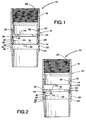
- FIGURE 1 is a side cross-sectional view of a well casing fill apparatus of the present invention in the open position.
- FIGURE 2 is a side cross-sectional view similar to FIG. 1, but showing the casing fill apparatus in the closed position.
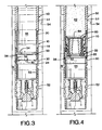
- FIGURES 3 - 6 are a sequential series of views illustrating the use of the casing fill apparatus of FIGS. 1 and 2 for filling a casing string as it is being run into a well bore and cementing the casing string in the well bore.
- the casing fill apparatus 10 includes a tubular housing 12 having an outer surface 14 and defining a longitudinal inner passage 16 therethrough.
- the elongated tubular housing 12 is preferably comprised of an upper tubular housing member 18 which is configured to be internally threadedly connected at the upper end 20 thereof to a casing string (not shown).
- the lower end 22 of the upper tubular housing member 18 includes an externally threaded recess 23 for connecting the housing member 18 to the upper end of a lower tubular housing member 24.
- the upper tubular housing member 24 includes an internal cylindrical recess 26, the upper end portion of which includes threads 28 for threaded connection to the upper tubular housing member 18.
- One or more well bore fluid fill ports 30 are formed in the lower tubular housing member 24.
- the member 24 includes four of the ports 30 equally spaced around the periphery thereof.
- the well bore fluids enter the interior of the casing by way of the ports 30 in the apparatus 10.
- a cylindrical closing sleeve 32 is slidably disposed within the internal cylindrical recess 26 of the lower tubular housing member 24.
- the cylindrical closing sleeve 32 is slidable between an upper open position illustrated in FIG. 1 whereby the well bore fluid fill ports 30 are uncovered by the closing sleeve 32 and a lower closed position shown in FIG. 2 whereby the closing sleeve 32 covers the ports 30.
- the closing sleeve 32 includes an annular cementing plug landing seat 34 at its upper end for receiving a cementing plug and slidably moving the closing sleeve 32 to the closed position as will be described further hereinbelow.
- At least one shear pin 33 or other similar shear means is provided connected between the lower tubular housing member 24 and the closing sleeve 32 to hold the closing sleeve 32 in the upper open position until the shear pin 33 is sheared as will be described hereinbelow.
- the closing sleeve 32 includes a continuous annular groove 35 formed in the outer cylindrical surface 36 thereof. An expandable locking ring 38 is disposed in the groove 35.
- a groove 40 which is of complimentary size and shape to the annular groove 35 is formed in the cylindrical inner surface 26 of the lower tubular housing member 24.
- the annular groove 40 is positioned with respect to the groove 35 in the closing sleeve 32 whereby when the shear pin 33 is sheared and the closing sleeve 32 is moved to the closed position (FIG. 2), the grooves 35 and 40 are positioned opposite each other and the expandable locking ring 38 expands into the groove 40 thereby locking the closing sleeve 32 in the closed position.
- the cylindrical outer surface 36 of the closing sleeve 32 includes two additional grooves 42 and 44 formed therein which contain O-ring sealing members for providing a seal between the outer surface 36 of the closing sleeve 32 and the inner surface 26 of the lower housing member 14. As shown in FIG. 2, when the closing sleeve 32 is in the closed position, the O-ring sealing members in the grooves 42 and 44 provide seals on both sides of the well bore fluid fill ports 30.
- the well casing fill apparatus 10 is shown threadedly connected in a casing string 50 which is being lowered into a well bore 54.
- the bottom end of the lower casing joint 51 making up the casing string 50 is threadedly connected to the upper threaded end 20 of the upper tubular housing member 18 and a conventional cementing float collar 52 is threadedly connected to the threaded lower end 53 of the lower tubular housing member 24.
- the casing string 50 is lowered in a well bore 54 which is filled with drilling and other well bore fluids 54.
- the closing sleeve 32 of the fill apparatus 10 is locked in the upper open position by the shear pin 33 so that the well bore fluids 55 flow through the fill ports 30 of the fill apparatus 10 into the interior of the casing string 50 as it is lowered.
- the casing string 50 reaches its total depth in the well bore 54, the casing string 50 and well bore 54 are filled with the well bore fluids 55 as shown in FIG. 3.
- a conventional cementing plug 60 is inserted in the casing string 50 and is displaced downwardly in the casing string 50 by a cement slurry 62 until the plug 60 seats on the seating surface 34 of the closing sleeve 32.
- the fluid pressure exerted on the cementing plug 60 by the cement slurry 62 is increased whereby the downward force on the closing sleeve 32 causes the shear pin 33 to shear and the closing sleeve 32 to move to its closed position as shown in FIG. 4.
- the lock ring 38 expands into the groove 40 and locks the closing sleeve 32 in the closed position.
- the pressure exerted by the cement slurry 62 on the cementing plug 60 is increased so that a rupture member 64 sealingly attached over an opening in the top of the cementing plug 60 ruptures and allows the cement slurry to flow through the cementing plug 60, through the fill apparatus 10 and through the float collar 52 into the annulus 66 between the casing string 50 and the walls of the well bore 54 as shown in FIG. 5.
- the cement slurry 62 is displaced into the annulus 66 until the annulus is filled with the cement slurry 62 and a second cementing plug 68 inserted in the casing string 50 behind the cement slurry 62 seats on the top of the first cementing plug 60 as shown in FIG. 6.
- the seating of the second cementing plug 68 on top of the first cementing plug 60 shuts off the flow of the cement slurry 62 into the annulus 66.
- the float collar 52 prevents back flow into the interior of the casing string 50.
- the cement slurry is allowed to set into a hard impermeable mass therein. Subsequently, if required, the cementing plugs 60 and 68, the closing sleeve seating surface 34 and the internals of the float collar 52 can be drilled out of the casing string 50.
- the casing fill apparatus of this invention can be inserted in a casing string at any desired threaded joint thereof or can be an integral part of a float collar or float shoe assembly. Also, the fill apparatus cannot be accidentally closed during the casing lowering operation and when the fill apparatus is closed, it is locked in the closed position. Further, the fill apparatus can be used with any type of single or multiple stage cementing equipment without requiring special procedures and/or apparatus for operating the fill apparatus.
Landscapes
- Engineering & Computer Science (AREA)
- Geology (AREA)
- Life Sciences & Earth Sciences (AREA)
- Mining & Mineral Resources (AREA)
- Environmental & Geological Engineering (AREA)
- Fluid Mechanics (AREA)
- Physics & Mathematics (AREA)
- General Life Sciences & Earth Sciences (AREA)
- Geochemistry & Mineralogy (AREA)
- Mechanical Engineering (AREA)
- Consolidation Of Soil By Introduction Of Solidifying Substances Into Soil (AREA)
- Soy Sauces And Products Related Thereto (AREA)
- Basic Packing Technique (AREA)
Applications Claiming Priority (2)
| Application Number | Priority Date | Filing Date | Title |
|---|---|---|---|
| US559704 | 1995-11-15 | ||
| US08/559,704 US5641021A (en) | 1995-11-15 | 1995-11-15 | Well casing fill apparatus and method |
Publications (3)
| Publication Number | Publication Date |
|---|---|
| EP0774564A2 true EP0774564A2 (de) | 1997-05-21 |
| EP0774564A3 EP0774564A3 (de) | 2001-10-10 |
| EP0774564B1 EP0774564B1 (de) | 2005-01-12 |
Family
ID=24234677
Family Applications (1)
| Application Number | Title | Priority Date | Filing Date |
|---|---|---|---|
| EP96308287A Expired - Lifetime EP0774564B1 (de) | 1995-11-15 | 1996-11-15 | Vorrichtung und Verfahren zum Füllen einer Bohrlochverrohrung |
Country Status (5)
| Country | Link |
|---|---|
| US (1) | US5641021A (de) |
| EP (1) | EP0774564B1 (de) |
| CA (1) | CA2190448C (de) |
| DE (1) | DE69634167T2 (de) |
| NO (1) | NO316329B1 (de) |
Cited By (4)
| Publication number | Priority date | Publication date | Assignee | Title |
|---|---|---|---|---|
| WO2000023687A1 (en) * | 1998-10-20 | 2000-04-27 | Halliburton Energy Services, Inc. | Universal cementing plug |
| GB2358208A (en) * | 2000-01-12 | 2001-07-18 | Sps Afos Group Ltd | Liner setting tool with radial washout ports |
| DE102004042956A1 (de) * | 2004-09-02 | 2006-04-20 | E.D.Oil Tools Service Rental Gmbh Vertr. D.D. Gf Ingo Reuter | Verfahren und Fülleinrichtung zum Auffüllen von Bohrzügen mit Bohrflüssigkeit |
| CN106223895A (zh) * | 2016-08-08 | 2016-12-14 | 中国海洋石油总公司 | 旋转阀 |
Families Citing this family (67)
| Publication number | Priority date | Publication date | Assignee | Title |
|---|---|---|---|---|
| US5909771A (en) * | 1994-03-22 | 1999-06-08 | Weatherford/Lamb, Inc. | Wellbore valve |
| US6279654B1 (en) * | 1996-10-04 | 2001-08-28 | Donald E. Mosing | Method and multi-purpose apparatus for dispensing and circulating fluid in wellbore casing |
| US5735348A (en) * | 1996-10-04 | 1998-04-07 | Frank's International, Inc. | Method and multi-purpose apparatus for dispensing and circulating fluid in wellbore casing |
| US7866390B2 (en) * | 1996-10-04 | 2011-01-11 | Frank's International, Inc. | Casing make-up and running tool adapted for fluid and cement control |
| US5918673A (en) * | 1996-10-04 | 1999-07-06 | Frank's International, Inc. | Method and multi-purpose apparatus for dispensing and circulating fluid in wellbore casing |
| US5960881A (en) * | 1997-04-22 | 1999-10-05 | Jerry P. Allamon | Downhole surge pressure reduction system and method of use |
| US5971079A (en) * | 1997-09-05 | 1999-10-26 | Mullins; Albert Augustus | Casing filling and circulating apparatus |
| US6098710A (en) * | 1997-10-29 | 2000-08-08 | Schlumberger Technology Corporation | Method and apparatus for cementing a well |
| US6675889B1 (en) | 1998-05-11 | 2004-01-13 | Offshore Energy Services, Inc. | Tubular filling system |
| US6390190B2 (en) | 1998-05-11 | 2002-05-21 | Offshore Energy Services, Inc. | Tubular filling system |
| US6082459A (en) | 1998-06-29 | 2000-07-04 | Halliburton Energy Services, Inc. | Drill string diverter apparatus and method |
| US6779599B2 (en) | 1998-09-25 | 2004-08-24 | Offshore Energy Services, Inc. | Tubular filling system |
| CA2360192C (en) | 1999-01-11 | 2008-06-10 | Weatherford/Lamb, Inc. | A pipe assembly and lubricating method |
| US6173777B1 (en) | 1999-02-09 | 2001-01-16 | Albert Augustus Mullins | Single valve for a casing filling and circulating apparatus |
| US6431626B1 (en) * | 1999-04-09 | 2002-08-13 | Frankis Casing Crew And Rental Tools, Inc. | Tubular running tool |
| US6318472B1 (en) | 1999-05-28 | 2001-11-20 | Halliburton Energy Services, Inc. | Hydraulic set liner hanger setting mechanism and method |
| US6182766B1 (en) | 1999-05-28 | 2001-02-06 | Halliburton Energy Services, Inc. | Drill string diverter apparatus and method |
| US6520257B2 (en) | 2000-12-14 | 2003-02-18 | Jerry P. Allamon | Method and apparatus for surge reduction |
| US6491103B2 (en) | 2001-04-09 | 2002-12-10 | Jerry P. Allamon | System for running tubular members |
| US6571876B2 (en) | 2001-05-24 | 2003-06-03 | Halliburton Energy Services, Inc. | Fill up tool and mud saver for top drives |
| US6651743B2 (en) | 2001-05-24 | 2003-11-25 | Halliburton Energy Services, Inc. | Slim hole stage cementer and method |
| US6722451B2 (en) | 2001-12-10 | 2004-04-20 | Halliburton Energy Services, Inc. | Casing while drilling |
| US6810958B2 (en) | 2001-12-20 | 2004-11-02 | Halliburton Energy Services, Inc. | Circulating cementing collar and method |
| US6508312B1 (en) * | 2002-02-13 | 2003-01-21 | Frank's Casing Crew And Rental Tools, Inc. | Flow control apparatus and method |
| US6796377B2 (en) * | 2002-07-23 | 2004-09-28 | Halliburton Energy Services, Inc. | Anti-rotation apparatus for limiting rotation of cementing plugs |
| US6772835B2 (en) | 2002-08-29 | 2004-08-10 | Halliburton Energy Services, Inc. | Apparatus and method for disconnecting a tail pipe and maintaining fluid inside a workstring |
| US6802374B2 (en) * | 2002-10-30 | 2004-10-12 | Schlumberger Technology Corporation | Reverse cementing float shoe |
| EP1639286B1 (de) * | 2003-06-17 | 2014-12-03 | Filtertek Inc. | Fluidhandhabungsvorrichtung |
| US6978844B2 (en) * | 2003-07-03 | 2005-12-27 | Lafleur Petroleum Services, Inc. | Filling and circulating apparatus for subsurface exploration |
| US6973969B2 (en) * | 2003-08-08 | 2005-12-13 | Halliburton Energy Services, Inc. | Apparatus and methods for preventing or limiting rotation of cementing plugs |
| US20070149076A1 (en) * | 2003-09-11 | 2007-06-28 | Dynatex | Cut-resistant composite |
| US7204304B2 (en) * | 2004-02-25 | 2007-04-17 | Halliburton Energy Services, Inc. | Removable surface pack-off device for reverse cementing applications |
| US7108068B2 (en) * | 2004-06-15 | 2006-09-19 | Halliburton Energy Services, Inc. | Floating plate back pressure valve assembly |
| US7252147B2 (en) * | 2004-07-22 | 2007-08-07 | Halliburton Energy Services, Inc. | Cementing methods and systems for initiating fluid flow with reduced pumping pressure |
| US7290611B2 (en) * | 2004-07-22 | 2007-11-06 | Halliburton Energy Services, Inc. | Methods and systems for cementing wells that lack surface casing |
| US7290612B2 (en) * | 2004-12-16 | 2007-11-06 | Halliburton Energy Services, Inc. | Apparatus and method for reverse circulation cementing a casing in an open-hole wellbore |
| US7322412B2 (en) * | 2004-08-30 | 2008-01-29 | Halliburton Energy Services, Inc. | Casing shoes and methods of reverse-circulation cementing of casing |
| US7303014B2 (en) * | 2004-10-26 | 2007-12-04 | Halliburton Energy Services, Inc. | Casing strings and methods of using such strings in subterranean cementing operations |
| US7284608B2 (en) * | 2004-10-26 | 2007-10-23 | Halliburton Energy Services, Inc. | Casing strings and methods of using such strings in subterranean cementing operations |
| US7303008B2 (en) | 2004-10-26 | 2007-12-04 | Halliburton Energy Services, Inc. | Methods and systems for reverse-circulation cementing in subterranean formations |
| US7270183B2 (en) | 2004-11-16 | 2007-09-18 | Halliburton Energy Services, Inc. | Cementing methods using compressible cement compositions |
| US7694732B2 (en) * | 2004-12-03 | 2010-04-13 | Halliburton Energy Services, Inc. | Diverter tool |
| US7322432B2 (en) * | 2004-12-03 | 2008-01-29 | Halliburton Energy Services, Inc. | Fluid diverter tool and method |
| US7481280B2 (en) * | 2005-06-20 | 2009-01-27 | 1243939 Alberta Ltd. | Method and apparatus for conducting earth borehole operations using coiled casing |
| US7322413B2 (en) * | 2005-07-15 | 2008-01-29 | Halliburton Energy Services, Inc. | Equalizer valve assembly |
| US20070068703A1 (en) * | 2005-07-19 | 2007-03-29 | Tesco Corporation | Method for drilling and cementing a well |
| US7357181B2 (en) * | 2005-09-20 | 2008-04-15 | Halliburton Energy Services, Inc. | Apparatus for autofill deactivation of float equipment and method of reverse cementing |
| US20070089678A1 (en) * | 2005-10-21 | 2007-04-26 | Petstages, Inc. | Pet feeding apparatus having adjustable elevation |
| US7533729B2 (en) * | 2005-11-01 | 2009-05-19 | Halliburton Energy Services, Inc. | Reverse cementing float equipment |
| US7392840B2 (en) * | 2005-12-20 | 2008-07-01 | Halliburton Energy Services, Inc. | Method and means to seal the casing-by-casing annulus at the surface for reverse circulation cement jobs |
| JP4410195B2 (ja) * | 2006-01-06 | 2010-02-03 | 株式会社東芝 | 半導体装置及びその製造方法 |
| NO324746B1 (no) * | 2006-03-23 | 2007-12-03 | Peak Well Solutions As | Verktoy for fylling, sirkulering og tilbakestromning av fluider i en bronn |
| US7597146B2 (en) * | 2006-10-06 | 2009-10-06 | Halliburton Energy Services, Inc. | Methods and apparatus for completion of well bores |
| US7533728B2 (en) | 2007-01-04 | 2009-05-19 | Halliburton Energy Services, Inc. | Ball operated back pressure valve |
| US7472752B2 (en) * | 2007-01-09 | 2009-01-06 | Halliburton Energy Services, Inc. | Apparatus and method for forming multiple plugs in a wellbore |
| US20080196889A1 (en) * | 2007-02-15 | 2008-08-21 | Daniel Bour | Reverse Circulation Cementing Valve |
| US7614451B2 (en) | 2007-02-16 | 2009-11-10 | Halliburton Energy Services, Inc. | Method for constructing and treating subterranean formations |
| US7654324B2 (en) * | 2007-07-16 | 2010-02-02 | Halliburton Energy Services, Inc. | Reverse-circulation cementing of surface casing |
| US20090107676A1 (en) * | 2007-10-26 | 2009-04-30 | Saunders James P | Methods of Cementing in Subterranean Formations |
| US8215404B2 (en) * | 2009-02-13 | 2012-07-10 | Halliburton Energy Services Inc. | Stage cementing tool |
| US8267174B2 (en) * | 2009-08-20 | 2012-09-18 | Halliburton Energy Services Inc. | Internal retention mechanism |
| US8230926B2 (en) * | 2010-03-11 | 2012-07-31 | Halliburton Energy Services Inc. | Multiple stage cementing tool with expandable sealing element |
| US8967255B2 (en) | 2011-11-04 | 2015-03-03 | Halliburton Energy Services, Inc. | Subsurface release cementing plug |
| US9683416B2 (en) | 2013-05-31 | 2017-06-20 | Halliburton Energy Services, Inc. | System and methods for recovering hydrocarbons |
| RU2526044C1 (ru) * | 2013-06-11 | 2014-08-20 | Открытое акционерное общество "Татнефть" имени В.Д. Шашина | Устройство для установки цементного моста в скважине |
| US11255146B2 (en) * | 2017-06-21 | 2022-02-22 | Drilling Innovative Solutions, Llc | Plug activated mechanical isolation device, systems and methods for controlling fluid flow inside a tubular in a wellbore |
| RU179812U1 (ru) * | 2017-12-25 | 2018-05-24 | Публичное акционерное общество "Татнефть" имени В.Д. Шашина | Устройство для цементирования обсадной колонны труб в скважине |
Family Cites Families (17)
| Publication number | Priority date | Publication date | Assignee | Title |
|---|---|---|---|---|
| US2155609A (en) * | 1937-01-23 | 1939-04-25 | Halliburton Oil Well Cementing | Multiple stage cementing |
| US2602510A (en) * | 1948-01-12 | 1952-07-08 | Baker Oil Tools Inc | Ported cementing apparatus |
| US2741314A (en) * | 1951-09-11 | 1956-04-10 | Johnston Testers Inc | Well testing valve |
| US2791279A (en) * | 1954-10-25 | 1957-05-07 | Baker Oil Tools Inc | Differential apparatus for automatically filling well casing |
| US2847074A (en) * | 1955-11-14 | 1958-08-12 | Halliburton Oil Well Cementing | Well casing fill-up device |
| US2947363A (en) * | 1955-11-21 | 1960-08-02 | Johnston Testers Inc | Fill-up valve for well strings |
| US2928470A (en) * | 1956-12-03 | 1960-03-15 | Baker Oil Tools Inc | Well cementing apparatus |
| US2998075A (en) * | 1957-07-29 | 1961-08-29 | Baker Oil Tools Inc | Subsurface well apparatus |
| US3338311A (en) * | 1964-12-14 | 1967-08-29 | Martin B Conrad | Stage cementing collar |
| US3559734A (en) * | 1968-09-19 | 1971-02-02 | Dow Chemical Co | Differential fill collar |
| US3527297A (en) * | 1969-02-17 | 1970-09-08 | Jerry L Pinkard | Stage cementer |
| US3633671A (en) * | 1970-01-19 | 1972-01-11 | Murphy Ind Inc G W | Cementing collar |
| US4298077A (en) * | 1979-06-11 | 1981-11-03 | Smith International, Inc. | Circulation valve for in-hole motors |
| GB8326959D0 (en) * | 1983-10-08 | 1983-11-09 | Hogarth P J M | Drilling apparatus |
| US4880058A (en) * | 1988-05-16 | 1989-11-14 | Lindsey Completion Systems, Inc. | Stage cementing valve |
| NO903764L (no) * | 1989-08-31 | 1991-03-01 | British Petroleum Co Plc | Ringrom-sikkerhetsventil. |
| US5234052A (en) * | 1992-05-01 | 1993-08-10 | Davis-Lynch, Inc. | Cementing apparatus |
-
1995
- 1995-11-15 US US08/559,704 patent/US5641021A/en not_active Expired - Lifetime
-
1996
- 1996-11-15 EP EP96308287A patent/EP0774564B1/de not_active Expired - Lifetime
- 1996-11-15 DE DE69634167T patent/DE69634167T2/de not_active Expired - Fee Related
- 1996-11-15 NO NO19964866A patent/NO316329B1/no not_active IP Right Cessation
- 1996-11-15 CA CA002190448A patent/CA2190448C/en not_active Expired - Fee Related
Non-Patent Citations (1)
| Title |
|---|
| None |
Cited By (11)
| Publication number | Priority date | Publication date | Assignee | Title |
|---|---|---|---|---|
| WO2000023687A1 (en) * | 1998-10-20 | 2000-04-27 | Halliburton Energy Services, Inc. | Universal cementing plug |
| US6196311B1 (en) | 1998-10-20 | 2001-03-06 | Halliburton Energy Services, Inc. | Universal cementing plug |
| EP1519004A1 (de) * | 1998-10-20 | 2005-03-30 | Halliburton Energy Services, Inc. | Verfahren zum Wischen der Innenfläche eines rohrförmigen Elementes und ein Stopfen zur Anwendung im genannten Verfahren |
| USRE41117E1 (en) | 1998-10-20 | 2010-02-16 | Halliburton Energy Services, Inc. | Universal cementing plug |
| USRE41508E1 (en) | 1998-10-20 | 2010-08-17 | Halliburton Energy Services, Inc. | Universal cementing plug |
| USRE42137E1 (en) | 1998-10-20 | 2011-02-15 | Halliburton Energy Services Inc. | Universal cementing plug |
| GB2358208A (en) * | 2000-01-12 | 2001-07-18 | Sps Afos Group Ltd | Liner setting tool with radial washout ports |
| DE102004042956A1 (de) * | 2004-09-02 | 2006-04-20 | E.D.Oil Tools Service Rental Gmbh Vertr. D.D. Gf Ingo Reuter | Verfahren und Fülleinrichtung zum Auffüllen von Bohrzügen mit Bohrflüssigkeit |
| DE102004042956B4 (de) * | 2004-09-02 | 2013-06-27 | E.D.Oil Tools Service Rental Gmbh Vertr. D.D. Gf Ingo Reuter | Verfahren und Fülleinrichtung zum Auffüllen von Bohrzügen mit Bohrflüssigkeit |
| CN106223895A (zh) * | 2016-08-08 | 2016-12-14 | 中国海洋石油总公司 | 旋转阀 |
| CN106223895B (zh) * | 2016-08-08 | 2018-11-27 | 中国海洋石油总公司 | 旋转阀 |
Also Published As
| Publication number | Publication date |
|---|---|
| EP0774564B1 (de) | 2005-01-12 |
| NO964866D0 (no) | 1996-11-15 |
| CA2190448C (en) | 2004-06-29 |
| DE69634167D1 (de) | 2005-02-17 |
| US5641021A (en) | 1997-06-24 |
| CA2190448A1 (en) | 1997-05-16 |
| DE69634167T2 (de) | 2006-01-05 |
| NO964866L (no) | 1997-05-16 |
| NO316329B1 (no) | 2004-01-12 |
| EP0774564A3 (de) | 2001-10-10 |
Similar Documents
| Publication | Publication Date | Title |
|---|---|---|
| US5641021A (en) | Well casing fill apparatus and method | |
| US5738171A (en) | Well cementing inflation packer tools and methods | |
| EP0709543B1 (de) | Vorrichtung und Verfahren zum Befüllen von Futterrohren und Spülungszirkulation | |
| US4986361A (en) | Well casing flotation device and method | |
| US5117915A (en) | Well casing flotation device and method | |
| US5181571A (en) | Well casing flotation device and method | |
| US5411095A (en) | Apparatus for cementing a casing string | |
| US6802374B2 (en) | Reverse cementing float shoe | |
| US5494107A (en) | Reverse cementing system and method | |
| CA2217939C (en) | Well cementing plug assemblies and methods | |
| US5443124A (en) | Hydraulic port collar | |
| US5456317A (en) | Buoyancy assisted running of perforated tubulars | |
| US5348089A (en) | Method and apparatus for the multiple stage cementing of a casing string in a well | |
| EP0846839B1 (de) | Verfahren und Vorrichtung zum Einbringen und Zementieren einer Verrohrung in horizontale Bohrungen | |
| US4044829A (en) | Method and apparatus for annulus pressure responsive circulation and tester valve manipulation | |
| EP1891296B1 (de) | Bohrlochstopfen mit positionierbarer Hülse | |
| US5193621A (en) | Bypass valve | |
| US6082459A (en) | Drill string diverter apparatus and method | |
| US4834176A (en) | Well valve | |
| CA2723012C (en) | Apparatus and method for drilling a wellbore with casing and cementing the casing in the wellbore | |
| US3260309A (en) | Liner cementing apparatus | |
| US3223159A (en) | Liner cementing method | |
| WO1991003620A1 (en) | Well casing flotation device and method | |
| US7694732B2 (en) | Diverter tool | |
| US2944606A (en) | Filling device |
Legal Events
| Date | Code | Title | Description |
|---|---|---|---|
| PUAI | Public reference made under article 153(3) epc to a published international application that has entered the european phase |
Free format text: ORIGINAL CODE: 0009012 |
|
| AK | Designated contracting states |
Kind code of ref document: A2 Designated state(s): DE FR GB IT NL |
|
| PUAL | Search report despatched |
Free format text: ORIGINAL CODE: 0009013 |
|
| AK | Designated contracting states |
Kind code of ref document: A3 Designated state(s): DE FR GB IT NL |
|
| 17P | Request for examination filed |
Effective date: 20011210 |
|
| 17Q | First examination report despatched |
Effective date: 20020830 |
|
| GRAP | Despatch of communication of intention to grant a patent |
Free format text: ORIGINAL CODE: EPIDOSNIGR1 |
|
| RAP1 | Party data changed (applicant data changed or rights of an application transferred) |
Owner name: HALLIBURTON ENERGY SERVICES, INC. |
|
| GRAS | Grant fee paid |
Free format text: ORIGINAL CODE: EPIDOSNIGR3 |
|
| GRAA | (expected) grant |
Free format text: ORIGINAL CODE: 0009210 |
|
| AK | Designated contracting states |
Kind code of ref document: B1 Designated state(s): DE FR GB IT NL |
|
| REG | Reference to a national code |
Ref country code: GB Ref legal event code: FG4D |
|
| REF | Corresponds to: |
Ref document number: 69634167 Country of ref document: DE Date of ref document: 20050217 Kind code of ref document: P |
|
| ET | Fr: translation filed | ||
| PGFP | Annual fee paid to national office [announced via postgrant information from national office to epo] |
Ref country code: FR Payment date: 20051108 Year of fee payment: 10 |
|
| PGFP | Annual fee paid to national office [announced via postgrant information from national office to epo] |
Ref country code: DE Payment date: 20051110 Year of fee payment: 10 |
|
| PLBE | No opposition filed within time limit |
Free format text: ORIGINAL CODE: 0009261 |
|
| STAA | Information on the status of an ep patent application or granted ep patent |
Free format text: STATUS: NO OPPOSITION FILED WITHIN TIME LIMIT |
|
| 26N | No opposition filed |
Effective date: 20051013 |
|
| PGFP | Annual fee paid to national office [announced via postgrant information from national office to epo] |
Ref country code: IT Payment date: 20061130 Year of fee payment: 11 |
|
| PG25 | Lapsed in a contracting state [announced via postgrant information from national office to epo] |
Ref country code: DE Free format text: LAPSE BECAUSE OF NON-PAYMENT OF DUE FEES Effective date: 20070601 |
|
| REG | Reference to a national code |
Ref country code: FR Ref legal event code: ST Effective date: 20070731 |
|
| PG25 | Lapsed in a contracting state [announced via postgrant information from national office to epo] |
Ref country code: FR Free format text: LAPSE BECAUSE OF NON-PAYMENT OF DUE FEES Effective date: 20061130 |
|
| PG25 | Lapsed in a contracting state [announced via postgrant information from national office to epo] |
Ref country code: IT Free format text: LAPSE BECAUSE OF NON-PAYMENT OF DUE FEES Effective date: 20071115 |
|
| PGFP | Annual fee paid to national office [announced via postgrant information from national office to epo] |
Ref country code: GB Payment date: 20151027 Year of fee payment: 20 |
|
| PGFP | Annual fee paid to national office [announced via postgrant information from national office to epo] |
Ref country code: NL Payment date: 20151106 Year of fee payment: 20 |
|
| REG | Reference to a national code |
Ref country code: NL Ref legal event code: MK Effective date: 20161114 |
|
| REG | Reference to a national code |
Ref country code: GB Ref legal event code: PE20 Expiry date: 20161114 |
|
| PG25 | Lapsed in a contracting state [announced via postgrant information from national office to epo] |
Ref country code: GB Free format text: LAPSE BECAUSE OF EXPIRATION OF PROTECTION Effective date: 20161114 |