EP2396232B2 - Folding box - Google Patents
Folding box Download PDFInfo
- Publication number
- EP2396232B2 EP2396232B2 EP10712689.8A EP10712689A EP2396232B2 EP 2396232 B2 EP2396232 B2 EP 2396232B2 EP 10712689 A EP10712689 A EP 10712689A EP 2396232 B2 EP2396232 B2 EP 2396232B2
- Authority
- EP
- European Patent Office
- Prior art keywords
- side wall
- folding box
- rotational position
- axle
- axis
- Prior art date
- Legal status (The legal status is an assumption and is not a legal conclusion. Google has not performed a legal analysis and makes no representation as to the accuracy of the status listed.)
- Active
Links
- 230000033001 locomotion Effects 0.000 description 7
- 239000002184 metal Substances 0.000 description 6
- 239000000243 solution Substances 0.000 description 6
- 230000003014 reinforcing effect Effects 0.000 description 5
- 230000008901 benefit Effects 0.000 description 3
- 238000006073 displacement reaction Methods 0.000 description 2
- 239000000463 material Substances 0.000 description 2
- 230000007246 mechanism Effects 0.000 description 2
- 230000006835 compression Effects 0.000 description 1
- 238000007906 compression Methods 0.000 description 1
- 230000001419 dependent effect Effects 0.000 description 1
- 230000008021 deposition Effects 0.000 description 1
- 238000011161 development Methods 0.000 description 1
- 230000018109 developmental process Effects 0.000 description 1
- 238000002347 injection Methods 0.000 description 1
- 239000007924 injection Substances 0.000 description 1
- 238000001746 injection moulding Methods 0.000 description 1
- 230000010354 integration Effects 0.000 description 1
- 238000012986 modification Methods 0.000 description 1
- 230000004048 modification Effects 0.000 description 1
- 230000003716 rejuvenation Effects 0.000 description 1
Images


Classifications
-
- B—PERFORMING OPERATIONS; TRANSPORTING
- B65—CONVEYING; PACKING; STORING; HANDLING THIN OR FILAMENTARY MATERIAL
- B65D—CONTAINERS FOR STORAGE OR TRANSPORT OF ARTICLES OR MATERIALS, e.g. BAGS, BARRELS, BOTTLES, BOXES, CANS, CARTONS, CRATES, DRUMS, JARS, TANKS, HOPPERS, FORWARDING CONTAINERS; ACCESSORIES, CLOSURES, OR FITTINGS THEREFOR; PACKAGING ELEMENTS; PACKAGES
- B65D11/00—Containers having bodies formed by interconnecting or uniting two or more rigid, or substantially rigid, components made wholly or mainly of plastics material
- B65D11/18—Containers having bodies formed by interconnecting or uniting two or more rigid, or substantially rigid, components made wholly or mainly of plastics material collapsible, i.e. with walls hinged together or detachably connected
- B65D11/1833—Containers having bodies formed by interconnecting or uniting two or more rigid, or substantially rigid, components made wholly or mainly of plastics material collapsible, i.e. with walls hinged together or detachably connected whereby all side walls are hingedly connected to the base panel
Definitions
- the invention relates to a folding box according to the preamble of claim 1.
- a folding box is made EP 1785360 .
- Folding boxes are practical tools for transporting items, since in an unfolded state, they form an open-topped box or box, and are flat in a folded state and therefore easy to stow. Compared to fixed boxes, this is a significant advantage.
- the use of folding boxes is limited by the usually lower stability or even prevented.
- the known locking mechanisms which lock the side walls against each other and so prevent collapse of the box, often unreliable or very complex.
- WO 00/68099 is also a portable, preferably made of plastic container known, which has a substantially rectangular bottom and two pairs of pivotally mounted side walls.
- bolts which are arranged on two of the side walls, are provided.
- the bolts can be moved between an unlocking position and a locking position. In the latter, the bolts protrude out of the side wall and engage in a recess of the adjacent side wall. Due to the displacement mechanism of the bolt, the container is technically relatively complicated. For many users or applications, such a box is therefore simply too expensive.
- the object of the invention is therefore to provide a folding box available which has improved protection against accidental folding.
- the folding box acts a non-circular, rotatable axle end on a side wall with a holding element on an adjacent side wall together such that the two walls are locked in a first rotational position of the axle end and unlocked in a second rotational direction.
- the folding box is secured against unintentional collapse, as for folding a multi-stage movement (unlocking with a first movement and collapsing with a second movement) is necessary.
- the folding box comes with relatively simple and therefore robust locking elements, because the pivot bearing of the axis is easier to accomplish than about a bearing that allows a longitudinal displacement of locking elements.
- a bearing eg, metal shaft, plastic bearing shell
- the axle and the bearing grind in operation can be intentionally tight, because the axle and the bearing grind in operation and thus provide an optimal fit of the parts over time.
- This is made possible by the fact that in the longitudinal direction always the same point of the axis in contact with the same point of storage.
- this is a clear advantage, since - which unfortunately can happen quite easily unintentionally - the rod-shaped locking elements are often bent and thus only a very loose storage of the locking elements is possible.
- According to the invention can be achieved by simple means as a high-quality, because tight-fitting, storage by the user.
- the at least one axle end has a cross section from the group: rectangular with rounded corners, S-shaped, oval, elliptical or flattened circular cross-section. These cross sections are comparatively easy to produce and at the same time very well fulfill a locking function.
- the at least one axis is automatically rotated by means of a spring in the first rotational position.
- the axis is therefore in the locked position by default. Unintentional unlocking is counteracted - since this requires the overcoming of a spring force.
- torsion springs, leaf springs and spiral tension and compression springs come into consideration here, wherein the force generated by a leaf or coil spring should optionally be converted into a torque with suitable measures (levers and the like).
- the at least one axis is automatically rotated into the second rotational position when the second side wall is opened.
- the invention thus moves the axis when opening the box by itself, that is, by the pivotal movement of the side wall, in the Entriegelposition, so that the side walls can be pivoted into their end positions without special intervention.
- the at least one axis is automatically turned into the first rotational position with the aid of the spring when the end position of the second side wall is reached.
- This variant of the invention represents a combination of the two aforementioned embodiments. On the one hand, unfolding of the side walls to their final position without special movements (ie without a conscious unlocking) allows, on the other hand, the side walls, once they have reached their final position, automatically by the Spring locked. Once the box is fully opened, it can not be accidentally closed. The actions required by the user for safe operation of a folding box are thus limited to a minimum.
- the at least one axis can be rotated by means of a handle in the first and / or second rotational position. Since the rotation of the axle can be quite cumbersome under certain circumstances without additional aids, in this embodiment of the invention, a handle on the axis is provided, which allows the easy turning of the same.
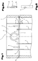
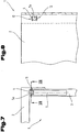
- Fig. 1 shows an inventive embodiment of a folding box 1 with a bottom (not shown), pivotally connected to the ground first and second side walls 2 and 3 and arranged on the first side walls 2 holding elements 4.
- On the second side wall 3 is an axis 5 with two axle ends 5a and 5b rotatably mounted in bearing shells 6, wherein the bearing shells 6 can be integrated in reinforcing ribs 7.
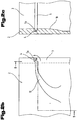
- FIGS. 2a to 2c show a first embodiment of the invention.
- Fig. 2a shows a side view of the axis 5 with the first axle end 5a, the lever 8 and the leaf springs 9.
- the axle ends 5a and 5b are S-shaped curved.
- Fig. 2b shows how the axle end 5a cooperates with the holding element 4.
- the axle end 5a is shown in the first rotational position, in which the side walls 2 and 3 are locked.
- the axle end 5a can be moved to a second rotational position, in which the axle end 5a is unlocked by the retaining element 4, so that the side walls 2 and 3 can be pivoted towards the bottom of the folding box 1.
- This rotation takes place by operating the lever 8 against the spring force of the leaf springs 9.
- the second side wall 3 is then pivoted in the direction of the ground, then - when the lever 8 is released again - the axle end 5a slowly rotates back into the through the widening guide gap first rotational position.
- lever unlocking is done by pressing the lever 8 inwards.
- the leaf springs 9 rest against the outside of the second side wall 3 and thus build up a restoring force.
- Fig. 2c finally shows a view of in Fig. 2b shown variant along the first side wall 2 (see also section BB in Fig. 2b ).
- Good to see here is the shape of the guide gap 10 and its boundary walls, which are flatter in the initial area and higher in the end. Due to the shape of the boundary walls of the guide gap 10 and the relatively large width at the beginning of the same, the axle ends 5a and 5b slip when folding the second side walls 3 particularly well in the associated guide gaps 10th
- FIGS. 3a to 3c show a second embodiment of the invention.
- Fig. 3a shows a side view of the axis 5 with the axle end 5a, the lever 8 and the leaf springs 9.
- the axle ends 5a and 5b are formed in the form of a flattened circular cross-section.
- Fig. 3b shows how the axle end 5a cooperates with the holding element 4.
- the axle end 5a is shown in the first rotational position, in which the side walls 2 and 3 are locked.
- the axle end 5b can be moved to a second rotational position, in which the axle end 5a is unlocked by the retaining element 4, so that the side walls 2 and 3 can be pivoted towards the bottom of the folding box 1.
- This rotation takes place by actuation of the lever 8 against the spring force of the leaf springs 9. If the second side wall 3 then in the direction of the ground pivoted, the axle end 5b rotates again after passing the retaining element 4 in the first rotational position.
- the axle end 5a When folding up the second side wall 3, the axle end 5a, as soon as it abuts the holding element 4, automatically rotated because of the eccentric force between the axle end 5a and retaining element 4 in the second rotational position. As soon as the second side wall 3 reaches its end position, however, the axle ends 5a and 5b are rotated by the leaf springs 9 into their first rotational position and then lock the side walls 2 and 3 with the aid of the retaining elements 4.
- Fig. 3c finally shows a plan view of a corner of the folding box 1, in which the first side wall 2 with the holding element 4 and the second side wall 3 with the axis 5 is shown. Good to see here is how the axle 5b interacts with the retaining element 4.
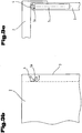
- FIGS. 4a to 4c now show an embodiment not according to the invention.
- Fig. 4a shows a side view of the axis 5 with the axle end 5a, the lever 8 and the leaf springs 9.
- the axle ends 5a and 5b are hook-shaped.
- Fig. 4b shows how the axle end 5a cooperates with the holding element 4.
- the axle end 5b is shown in the first rotational position, in which the side walls 2 and 3 are locked.
- the axle end 5b can be moved to a second rotational position, in which the axle end 5b is unlocked by the retaining element 4, so that the side walls 2 and 3 can be pivoted towards the bottom of the folding box 1.
- This rotation takes place by actuation of the lever 8 against the spring force of the leaf springs 9.
- the axle end 5b turns back into the first rotational position after passing through the retaining element 4.
- Fig. 4c finally shows a plan view of a corner of the folding box 1, in which the first side wall 2 with the holding element 4 and the second side wall 3 with the axis 5 is shown. Good to see here is how the axle end 5a cooperates with the retaining element 4.
- the bearing of the axle 5 can advantageously be accomplished by integration of the bearing shells 6 in reinforcing ribs 7 of the second side wall 3.
- Fig. 5 shows a part of a reinforcing rib 7, in which a bearing shell 6 is arranged (see also section AA in Fig. 1 ).
- the bearing shell 6 advantageously comprises a little more than a semicircle, so that the axis 5 can be simply clipped in the assembly of the folding box 1.
- cuts are provided in addition to the bearing shell 6, which allow springs of the bearing shell 6 when clipping.
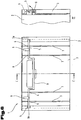
- Fig. 6 shows in a side view and a section CC a folding box 1 finally a variant of an axis 5, which is not continuous, but in which the lever 8, the axis 5, in particular in the middle divides, in particular the lever 8 and the axis 5 in the middle region provided with a pulled down deposition.
- the lever 8 and the axis 5 may be constructed in one piece but also in several pieces.
- This lever 8, which is pivotally formed below the handle of the folding box 1, can be used in all mentioned variants of the invention.
- To unlock the lever 8 is folded outwards.
- the leaf springs 9 lie on the outside of the second side wall 3 and thus cause a restoring force.
- a mirror-inverted embodiment is conceivable in which the lever 8 is pressed inwards, and the leaf springs 9 lie on the inside.
- FIGS. 7 and 8 is a detail of another embodiment of the invention, which differs from that according to Fig. 1 derives and differs essentially only by another embodiment of the axle ends 5a and the holding elements 4, shown in plan view and side view.
- Fig. 7 shows a plan view of a corner of the folding box 1, in which the first side wall 2 with the holding element 4 and the second side wall 3 with the axis 5 is shown. It can again be seen how the axle end 5a interacts with the retaining element 4.
- the lever 8 ( Fig. 1 ) on the second, in particular short, side wall 3 of the folding box 1 is pressed inwards (in the direction of the box interior), or, as already described above, the mirror-inverted embodiment variant is also possible.
- the axis 8, which is in particular firmly connected to the lever 8, is set in a rotary motion.
- a taper 11, ie the axis 5 is formed tapered, arranged in the first side wall 2, that is, the holding element 4, engages and locked.
- This lock is shaped so that it in the closed state, ie erected state of the side walls 2, 3 of the folding box 1, locked.
- the holding element 4 is provided with two opposing shells 12 which receive the tapered axle end 5a of the axle 5 ( Fig. 8 ).
- the lock is released, so that the oval-shaped in cross-section axle end 5 a can be brought out of engagement with the shells 12.
- the second side wall 3 can be folded inwards.
- folding the second side wall 3 in the holding element 4 in turn provide the leaf springs 9 ( Fig. 1 ) that the lever 8 ( Fig. 1 ) is brought back to its starting position or rest position.
- the axle end 5a is pressed into the flexible shells 12.
- the lever 8 remains in its initial position.
- the folding box 1 is thus locked again.
- the axis 5 during assembly of the lock in the spring openings or the bearing shell 6 ( Fig. 5 ) of the reinforcing rib (s) 7 are clipped.
- the axis 5 may be made of metal, for example.
- the lever 8 and / or the leaf springs 9 may also be made of metal and welded to the axis 5. It is also conceivable that the lever 8 and / or the leaf springs 9 are made of plastic and are sprayed for example on the axis 5. Finally, it is also possible to produce axis 5, lever 8 and the leaf springs 9 in one piece from metal or plastic. For the latter variant, in particular cost-effective and in the form almost completely freely selectable injection molded parts into consideration.
- the axle ends 5a and 5b can be given any desired shape during injection molding, but can also be produced by grinding (for example flattening of a wire that is circular in the raw state) or pressing.
- axle ends 5a and 5b made of plastic can be plugged onto an axle 5 made of metal, but it is also possible to attach axle ends 5a and 5b made of metal to an axle 5 made of plastic.
- axle ends 5a and 5b protrude on both sides of the second side wall 3
- other variants are conceivable, of course.
- a first axle end 5a can protrude on the second side wall 3.
- the folding box 1 is locked only on one side.
- two axes 5 are arranged with a total of four axle ends.
Description
Die Erfindung betrifft eine Klappbox entsprechend dem Oberbegriff des Anspruchs 1. So eine Klappbox ist aus
Klappboxen sind praktische Hilfsmittel zum Transport von Gegenständen, da sie in einem aufgeklappten Zustand eine nach oben geöffnete Box oder Kiste bilden und in einem zusammengeklappten Zustand flach und daher leicht zu verstauen sind. Gegenüber fixen Boxen ist dies ein wesentlicher Vorteil. Allerdings wird der Einsatz von Klappboxen durch die in aller Regel geringere Stabilität eingeschränkt oder gar verhindert. Darüber hinaus sind die bekannten Verriegelungsmechanismen, welche die Seitenwände gegeneinander verriegeln und so ein Zusammenklappen der Box verhindern sollen, oft unzuverlässig oder aber auch sehr komplex aufgebaut.Folding boxes are practical tools for transporting items, since in an unfolded state, they form an open-topped box or box, and are flat in a folded state and therefore easy to stow. Compared to fixed boxes, this is a significant advantage. However, the use of folding boxes is limited by the usually lower stability or even prevented. In addition, the known locking mechanisms, which lock the side walls against each other and so prevent collapse of the box, often unreliable or very complex.
Beispielsweise ist aus der
Aus der
Aufgabe der Erfindung ist es daher, eine Klappbox zur Verfügung zu stellen, welche einen verbesserten Schutz gegen unbeabsichtigtes Einklappen aufweist.The object of the invention is therefore to provide a folding box available which has improved protection against accidental folding.
Die Aufgabe der Erfindung wird mit einer Klappbox nach Patentanspruch 1 gelöst, nämlich einer Klappbox, umfassend
- einen Boden,
- mit dem Boden schwenkbar verbundene erste und zweite Seitenwände, die mit dem Boden in einem aufgeklappten Zustand eine nach oben offene Box bilden,
- zumindest ein auf einer ersten Seitenwand angeordnetes Halteelement,
- zumindest eine auf einer zweiten Seitenwand drehbar gelagerte Achse, wobei die zumindest eine Achse an zumindest einem Achsende einen von der Kreisform abweichenden Querschnitt aufweist und das zumindest eine Achsende in einer ersten Drehstellung mit dem zumindest einen Halteelement die erste mit der zweiten Seitenwand verriegelt und in einer zweiten Drehstellung besagte Seitenwände entriegelt, und wobei das zumindest eine Achsende (2, 3) einen Querschnitt ausgewählt aus der Gruppe umfassend rechteckförmig mit gerundeten Ecken, S-förmig, oval, ellipsenförmig oder abgeflachter Kreisquerschnitt, aufweist.
- a floor,
- pivotally connected to the floor first and second side walls, which form an open-topped box with the bottom in an unfolded state,
- at least one holding element arranged on a first side wall,
- at least one axis rotatably mounted on a second side wall, wherein the at least one axis has at least one axis end deviating from the circular cross-section and the at least one axle end in a first rotational position with the at least one holding element, the first locked with the second side wall and in a second rotational position said side walls unlocked, and wherein the at least one axle end (2, 3) has a cross section selected from the group comprising rectangular with rounded corners, S-shaped, oval, elliptical or flattened circular cross-section.
Es wirkt also ein nicht-kreisförmiges, drehbares Achsende auf einer Seitenwand mit einem Halteelement auf einer benachbarten Seitenwand derart zusammen, dass die beiden Wände in einer ersten Drehstellung des Achsendes verriegelt und in einer zweiten Drehrichtung entriegelt werden. Daraus ergeben sich unmittelbar einige Vorteile. Beispielsweise ist die Klappbox gegen unbeabsichtigtes Zusammenklappen gesichert, da für das Zusammenklappen ein mehrstufiger Bewegungsablauf (Entriegeln mit einer ersten Bewegung und Zusammenklappen mit einer zweiten Bewegung) nötig ist. Weiterhin kommt die Klappbox mit relativ einfachen und daher robusten Verriegelungselementen aus, denn die Drehlagerung der Achse ist einfacher zu bewerkstelligen als etwa eine Lagerung, die eine Längsverschiebung von Verriegelungselementen ermöglicht. Beispielsweise kann eine Lagerung (z.B. Achse aus Metall, Lagerschale aus Kunststoff) im Auslieferungszustand absichtlich stramm ausgeführt sein, da sich die Achse und die Lagerung im Betrieb einschleifen und so im Lauf der Zeit einen optimalen Sitz der Teile ergeben. Dies wird durch den Umstand ermöglicht, dass in Längsrichtung immer dieselbe Stelle der Achse mit derselben Stelle der Lagerung in Kontakt ist. Gegenüber einer Schiebelagerung nach dem Stand der Technik ist dies ein klarer Vorteil, da - was leider recht leicht unbeabsichtigt geschehen kann - die stangenförmigen Verriegelungselemente häufig verbogen sind und somit nur eine sehr lose Lagerung der Verriegelungselemente möglich ist. Erfindungsgemäß kann dagegen eine vom Benutzer als qualitativ hochwertig erachtete, weil stramm sitzende, Lagerung mit einfachen Mitteln erreicht werden. Weiterhin kommt die erfindungsgemäße Lösung - wenn die Achse durchgehend ist - prinzipiell mit lediglich zwei Lagerungen aus, wohingegen nach dem Stand der Technik wenigstens vier Lagerstellen für die verschiebbaren Verriegelungselemente nötig sind. Schließlich neigen verschiebbare Verriegelungselemente zum Verhaken, etwa wenn festsitzender Schmutz oder Materialunebenheiten die Bewegung durch eine Lagerung erschweren oder verhindern. Bei Drehlagerungen ist dieses Phänomen dagegen weitgehend unbekannt. Die Erfindung ist daher einfacher, zuverlässiger und mit einfacheren Mitteln qualitativ hochwertig herstellbar als dies bei bekannten Lösungen der Fall ist.So it acts a non-circular, rotatable axle end on a side wall with a holding element on an adjacent side wall together such that the two walls are locked in a first rotational position of the axle end and unlocked in a second rotational direction. This results in some immediate benefits. For example, the folding box is secured against unintentional collapse, as for folding a multi-stage movement (unlocking with a first movement and collapsing with a second movement) is necessary. Furthermore, the folding box comes with relatively simple and therefore robust locking elements, because the pivot bearing of the axis is easier to accomplish than about a bearing that allows a longitudinal displacement of locking elements. For example, a bearing (eg, metal shaft, plastic bearing shell) in the delivery state can be intentionally tight, because the axle and the bearing grind in operation and thus provide an optimal fit of the parts over time. This is made possible by the fact that in the longitudinal direction always the same point of the axis in contact with the same point of storage. Opposite one Sliding bearing according to the prior art, this is a clear advantage, since - which unfortunately can happen quite easily unintentionally - the rod-shaped locking elements are often bent and thus only a very loose storage of the locking elements is possible. According to the invention, however, can be achieved by simple means as a high-quality, because tight-fitting, storage by the user. Furthermore, the solution according to the invention - when the axis is continuous - in principle with only two bearings, whereas according to the prior art, at least four bearings for the sliding locking elements are necessary. Finally, slidable locking elements tend to catch, such as when stuck dirt or material bumps complicate the movement through storage or prevent. In rotary bearings, however, this phenomenon is largely unknown. The invention is therefore simpler, more reliable and with simpler means of high quality to produce than is the case with known solutions.
Das zumindest eine Achsende weist einen Querschnitt aus der Gruppe: rechteckförmig mit gerundeten Ecken, S-förmig, oval, ellipsenförmig oder abgeflachter Kreisquerschnitt auf. Diese Querschnitte sind vergleichsweise einfach herstellbar und erfüllen gleichzeitig sehr gut eine Verriegelungsfunktion.The at least one axle end has a cross section from the group: rectangular with rounded corners, S-shaped, oval, elliptical or flattened circular cross-section. These cross sections are comparatively easy to produce and at the same time very well fulfill a locking function.
Vorteilhafte Ausgestaltungen und Weiterbildungen der Erfindung ergeben sich aus den Unteransprüchen sowie aus der Beschreibung in Zusammenschau mit den Figuren der Zeichnung.Advantageous embodiments and modifications of the invention will become apparent from the dependent claims and from the description in conjunction with the figures of the drawing.
Besonders vorteilhaft ist es, wenn die zumindest eine Achse mit Hilfe einer Feder automatisch in die erste Drehstellung gedreht wird. Bei dieser Variante befindet sich die Achse standardmäßig also in der Verriegelposition. Einem unbeabsichtigten Entriegeln wird - da es hierzu der Überwindung einer Federkraft bedarf- entgegengewirkt. In Betracht kommen hier beispielsweise alle Arten von Torsionsfedern, Blattfedern sowie spiralförmige Zug- und Druckfedern, wobei die durch eine Blatt- oder Spiralfeder erzeugte Kraft mit geeigneten Maßnahmen (Hebeln und dergleichen) gegebenenfalls in ein Drehmoment umgewandelt werden sollte.It when the at least one axis is automatically rotated by means of a spring in the first rotational position is particularly advantageous. In this variant, the axis is therefore in the locked position by default. Unintentional unlocking is counteracted - since this requires the overcoming of a spring force. For example, all types of torsion springs, leaf springs and spiral tension and compression springs come into consideration here, wherein the force generated by a leaf or coil spring should optionally be converted into a torque with suitable measures (levers and the like).
Besonders vorteilhaft ist es weiterhin, wenn die zumindest eine Achse beim Aufklappen der zweiten Seitenwand automatisch in die zweite Drehstellung gedreht wird. Bei dieser Variante der Erfindung bewegt sich die Achse beim Aufklappen der Box also von selbst, das heißt durch die Schwenkbewegung der Seitenwand, in die Entriegelposition, sodass die Seitenwände ohne besonderes Zutun in ihre Endlagen geschwenkt werden können.It is furthermore particularly advantageous if the at least one axis is automatically rotated into the second rotational position when the second side wall is opened. In this variant The invention thus moves the axis when opening the box by itself, that is, by the pivotal movement of the side wall, in the Entriegelposition, so that the side walls can be pivoted into their end positions without special intervention.
Besonders vorteilhaft ist es schließlich, wenn die zumindest eine Achse bei Erreichen der Endstellung der zweiten Seitenwand mit Hilfe der Feder automatisch in die erste Drehstellung gedreht wird. Diese Variante der Erfindung stellt eine Kombination der beiden vorgenannten Ausführungsformen dar. Einerseits wird ein Aufklappen der Seitenwände bis in ihre Endlage ohne besondere Bewegungsabläufe (d.h. ohne ein bewusstes Entriegeln) ermöglicht, andererseits werden die Seitenwände, sobald sie ihre Endposition erreicht haben, automatisch durch die Feder verriegelt. Ist die Box also einmal vollständig aufgeklappt, dann kann sie nicht mehr unbeabsichtigt zugeklappt werden. Die vom Benutzer geforderten Handlungen zur sicheren Bedienung einer Klappbox sind hier also auf ein Minimum beschränkt.Finally, it is particularly advantageous if the at least one axis is automatically turned into the first rotational position with the aid of the spring when the end position of the second side wall is reached. This variant of the invention represents a combination of the two aforementioned embodiments. On the one hand, unfolding of the side walls to their final position without special movements (ie without a conscious unlocking) allows, on the other hand, the side walls, once they have reached their final position, automatically by the Spring locked. Once the box is fully opened, it can not be accidentally closed. The actions required by the user for safe operation of a folding box are thus limited to a minimum.
Vorteilhaft ist es auch, wenn die zumindest eine Achse mit Hilfe eines Griffes in die erste und/oder zweite Drehstellung gedreht werden kann. Da das Drehen der Achse ohne weitere Hilfsmittel unter Umständen recht mühsam sein kann, wird bei dieser Ausführungsform der Erfindung ein Griff an der Achse vorgesehen, der das leichte Drehen derselben ermöglicht.It is also advantageous if the at least one axis can be rotated by means of a handle in the first and / or second rotational position. Since the rotation of the axle can be quite cumbersome under certain circumstances without additional aids, in this embodiment of the invention, a handle on the axis is provided, which allows the easy turning of the same.
Die obigen Ausgestaltungen und Weiterbildungen der Erfindung können auf beliebige Art und Weise kombiniert werden.The above embodiments and further developments of the invention can be combined in any manner.
Zum besseren Verständnis der Erfindung wird diese anhand der nachfolgenden Figuren näher erläutert.For a better understanding of the invention, this will be explained in more detail with reference to the following figures.
Es zeigen jeweils in stark schematisch vereinfachter Darstellung:
- Fig. 1
- eine Seitenansicht einer erfindungsgemäßen Klappbox;
- Fig. 2a
- eine erste, S-förmige Variante eines Achsendes;
- Fig. 2b
- eine Detailansicht, wie die erste Variante des Achsendes mit einem Halteelement auf der ersten Seitenwand zusammenwirkt;
- Fig. 2c
- die Detailansicht aus
Fig. 2b nur aus einer anderen Richtung; - Fig. 3a
- eine zweite Variante eines Achsendes mit abgeflachtem Kreisquerschnitt;
- Fig. 3b
- eine Detailansicht wie die zweite Variante des Achsendes mit einem Halteelement auf der ersten Seitenwand zusammenwirkt;
- Fig. 3c
- die Detailansicht aus
Fig. 3b nur von oben gesehen; - Fig. 4a
- eine nicht erfindungsgemäße Variante eines Achsendes;
- Fig. 4b
- eine Detailansicht wie die nicht erfindungsgemäße Variante des Achsendes mit einem Halteelement auf der ersten Seitenwand zusammenwirkt;
- Fig. 4c
- die Detailansicht aus
Fig. 4b nur von oben gesehen; - Fig. 5
- eine Lagerschale zur Aufnahme der Achse;
- Fig. 6
- eine Variante eines Hebels zur Drehung der Achse;
- Fig. 7
- ein Detail aus einer Ausführungsvariante mit elliptischem Achsende in Draufsicht;
- Fig. 8
- die Ausführungsvariante nach
Fig. 7 in Seitenansicht gemäß der Schnittlinie VIII-VIII inFig. 7 .
- Fig. 1
- a side view of a folding box according to the invention;
- Fig. 2a
- a first, S-shaped variant of an axle end;
- Fig. 2b
- a detailed view of how the first variant of the axle end cooperates with a holding element on the first side wall;
- Fig. 2c
- the detail view
Fig. 2b only from another direction; - Fig. 3a
- a second variant of a Achsendes with flattened circular cross-section;
- Fig. 3b
- a detailed view of how the second variant of the axle end cooperates with a holding element on the first side wall;
- Fig. 3c
- the detail view
Fig. 3b seen from above only; - Fig. 4a
- a not inventive variant of a Achsendes;
- Fig. 4b
- a detailed view of how the non-inventive variant of the axle end cooperates with a holding element on the first side wall;
- Fig. 4c
- the detail view
Fig. 4b seen from above only; - Fig. 5
- a bearing shell for receiving the axle;
- Fig. 6
- a variant of a lever for rotating the axle;
- Fig. 7
- a detail of a variant with elliptical axle end in plan view;
- Fig. 8
- the embodiment according to
Fig. 7 in side view along the section line VIII-VIII inFig. 7 ,
Einführend wird festgehalten, dass in den unterschiedlich beschriebenen Ausführungsformen gleiche Teile mit gleichen Bezugszeichen bzw. gleichen Bauteilbezeichnungen versehen werden, wobei die in der gesamten Beschreibung enthaltenen Offenbarungen sinngemäß auf gleiche Teile mit gleichen Bezugszeichen bzw. gleichen Bauteilbezeichnungen übertragen werden können. Auch sind die in der Beschreibung gewählten Lageangaben, wie z.B. oben, unten, seitlich usw. auf die unmittelbar beschriebene sowie dargestellte Figur bezogen und sind bei einer Lageänderung sinngemäß auf die neue Lage zu übertragen. Weiterhin können auch Einzelmerkmale oder Merkmalskombinationen aus den gezeigten und beschriebenen unterschiedlichen Ausführungsbeispielen für sich eigenständige, erfinderische oder erfmdungsgemäße Lösungen darstellen.By way of introduction, it is stated that in the differently described embodiments, the same parts are provided with the same reference numerals or the same component designations, wherein the disclosures contained in the entire description can be mutatis mutandis to the same parts with the same reference numerals and component names. Also, the position information selected in the description, such as top, bottom, side, etc. related to the immediately described and illustrated figure and are to be transferred to a new position analogous to the new situation. You can also continue Represent individual features or combinations of features from the illustrated and described different embodiments for themselves, inventive or erfmdungsgemäße solutions.
Die Ausführungsbeispiele zeigen mögliche Ausführungsvarianten einer erfindungsgemäßen Klappbox, wobei an dieser Stelle bemerkt sei, dass die Erfindung nicht auf die speziell dargestellten Ausführungsvarianten derselben eingeschränkt ist, sondern vielmehr auch diverse Kombinationen der einzelnen Ausführungsvarianten untereinander möglich sind und diese Variationsmöglichkeit aufgrund der Lehre zum technischen Handeln durch gegenständliche Erfindung im Können des auf diesem technischen Gebiet tätigen Fachmannes liegt.The embodiments show possible embodiments of a folding box according to the invention, which should be noted at this point that the invention is not limited to the specifically illustrated embodiments thereof, but also various combinations of the individual embodiments are possible with each other and this possibility of variation due to the teaching of technical action representational invention in the skill of those skilled in this technical field.
Die
Denkbar ist natürlich auch eine spiegelverkehrte Ausführung, bei welcher der Hebel 8 nach außen gedrückt wird.It is also conceivable, of course, a mirrored version in which the
Wird die Seitenwand 2 hochgeklappt, so wird das Achsende 5a durch den sich verjüngenden Führungsspalt 10 dagegen langsam in die zweite Drehstellung, die Entriegelstellung, bewegt. Bei vollständigem Hochklappen der Seitenwand 2 schlüpft nun das Achsende 5a in das Halteelement 4 und nimmt dort aufgrund der Federkraft der Blattfedern 9 die erste Drehstellung, die Verriegelposition, ein. Das Verriegeln erfolgt also automatisch beim Hochschwenken der zweiten Seitenwand 3 in deren Endstellung, das Entriegeln dagegen durch Betätigung des Hebels 8 entgegen der Federkraft der Blattfedern 9. Ein unbeabsichtigtes Öffnen der Klappbox 1 kann daher mehr oder minder ausgeschlossen werden, ohne dass dadurch der Komfort beim Hochklappen der Seitenwände 2 und 3 verloren gehen würde.If the
Die
Die
In allen genannten Varianten der Erfindung kann die Lagerung der Achse 5 vorteilhaft durch Integration der Lagerschalen 6 in Verstärkungsrippen 7 der zweiten Seitenwand 3 bewerkstelligt sein.
In den
Zum Öffnen der Klappbox 1 wird der Hebel 8 (
In allen Varianten der Erfindung kann die Achse 5 beispielsweise aus Metall hergestellt sein. Beispielsweise können der Hebel 8 und/oder die Blattfedern 9 ebenfalls aus Metall gefertigt und auf die Achse 5 aufgeschweißt sein. Denkbar ist aber auch, dass der Hebel 8 und/oder die Blattfedern 9 aus Kunststoff gefertigt sind und beispielsweise auf die Achse 5 aufgespritzt sind. Schließlich ist auch möglich, Achse 5, Hebel 8 und die Blattfedern 9 einstückig aus Metall oder auch Kunststoff herzustellen. Für letztere Variante kommen insbesondere kostengünstige und in der Form fast völlig frei wählbare Spritzgussteile in Betracht. Die Achsenden 5a und 5b können schon beim Spritzgießen eine beliebige Form erhalten, können aber auch etwa durch Schleifen (etwa Abflachen eines im Rohzustand kreisförmigen Drahtes) oder Pressen hergestellt sein. Schließlich können für die Achse 5 und deren Enden 5a und 5b auch unterschiedliche Materialien verwendet werden. Beispielsweise können Achsenden 5a und 5b aus Kunststoff auf eine Achse 5 aus Metall aufgesteckt werden, aber auch das Aufstecken von Achsenden 5a und 5b aus Metall auf eine Achse 5 aus Kunststoff ist möglich.In all variants of the invention, the
Obwohl in den Figuren stets davon ausgegangen wurde, dass die Achsenden 5a und 5b an beiden Seiten der zweiten Seitenwand 3 hervorragen, sind selbstverständlich auch andere Varianten denkbar. Beispielsweise kann auch nur ein erstes Achsende 5a an der zweiten Seitenwand 3 hervorragen. In diesem Fall wird die Klappbox 1 bloß einseitig verriegelt. Denkbar ist auch, dass an der zweiten Seitenwand 3 zwei Achsen 5 mit insgesamt vier Achsenden angeordnet sind. Vorteilhaft befinden sich an der Klappbox 1 jedoch vier Stellen, an denen verriegelt wird, nämlich an beiden Seiten der beiden zweiten Seitenwände 3. Das ergibt eine Verriegelung pro Ecke der Klappbox 1.Although it has always been assumed in the figures that the axle ends 5a and 5b protrude on both sides of the
Der Ordnung halber sei abschließend darauf hingewiesen, dass zum besseren Verständnis des Aufbaus der Klappbox 1 diese bzw. deren Bestandteile teilweise unmaßstäblich und/oder vergrößert und/oder verkleinert dargestellt wurden.For the sake of order, it should finally be pointed out that, for a better understanding of the structure of the
Die den eigenständigen erfinderischen Lösungen zugrunde liegende Aufgabe kann der Beschreibung entnommen werden.The problem underlying the independent inventive solutions can be taken from the description.
Vor allem können die einzelnen in den
- 11
- Klappboxfolding
- 22
- erste Seitenwandfirst sidewall
- 33
- zweite Seitenwandsecond side wall
- 44
- Halteelementretaining element
- 55
- Achseaxis
- 5a5a
- erstes Achsendefirst axle end
- 5b5b
- zweites Achsendesecond axle end
- 66
- Lagerschalebearing shell
- 77
- Verstärkungsrippereinforcing rib
- 88th
- Hebellever
- 99
- Blattfederleaf spring
- 1010
- Führungsspaltguide gap
- 1111
- Verjüngungrejuvenation
- 1212
- SchaleBowl
Claims (5)
- Folding box (1), comprising:- a base,- first and second side walls (2, 3) pivotably connected to the base which, together with the base, form a box open at the top in the folded open state,- at least one retaining element (4) disposed on a first side wall (2),- at least one pin (5) mounted so as to be rotatable on a second side wall (3),where the at least one pin (5) has a cross-section that is not circular on at least one pin end (5a, 5b) and the at least one pin end (5a, 5b) locks the first to the second side wall (2, 3) by means of the retaining element (4) in a first rotational position and unlocks said side walls (2, 3) in a second rotational position, characterised in that the at least one pin end (2, 3) has a cross-section selected from the group comprising rectangular with rounded corners, S-shaped, oval, ellipsoid or a flattened circular cross-section.
- Folding box (1) as claimed in claim 1, characterised in that the at least one pin (5) can be automatically rotated into the first rotational position with the aid of a spring (9).
- Folding box (1) as claimed in claim 1, characterised in that the at least one pin (5) can be automatically rotated into the second rotational position as the second side wall (3) is folded open.
- Folding box (1) as claimed in claim 2 and 3, characterised in that the at least one pin (5) can be automatically rotated into the first rotational position with the aid of the spring (9) once the second side wall (3) has assumed the end position.
- Folding box (1) as claimed in one of claims 1 to 4, characterised in that the at least one pin (5) can be rotated into the first and/or second rotational position by means of a handle (8).
Priority Applications (2)
| Application Number | Priority Date | Filing Date | Title |
|---|---|---|---|
| EP13003320.2A EP2647580B1 (en) | 2009-02-12 | 2010-02-11 | Collapsible box |
| PL10712689T PL2396232T5 (en) | 2009-02-12 | 2010-02-11 | Folding box |
Applications Claiming Priority (2)
| Application Number | Priority Date | Filing Date | Title |
|---|---|---|---|
| AT0023209A AT507858B1 (en) | 2009-02-12 | 2009-02-12 | folding |
| PCT/AT2010/000040 WO2010091447A1 (en) | 2009-02-12 | 2010-02-11 | Folding box |
Related Child Applications (2)
| Application Number | Title | Priority Date | Filing Date |
|---|---|---|---|
| EP13003320.2A Division EP2647580B1 (en) | 2009-02-12 | 2010-02-11 | Collapsible box |
| EP13003320.2A Division-Into EP2647580B1 (en) | 2009-02-12 | 2010-02-11 | Collapsible box |
Publications (3)
| Publication Number | Publication Date |
|---|---|
| EP2396232A1 EP2396232A1 (en) | 2011-12-21 |
| EP2396232B1 EP2396232B1 (en) | 2013-07-03 |
| EP2396232B2 true EP2396232B2 (en) | 2017-01-18 |
Family
ID=42154656
Family Applications (2)
| Application Number | Title | Priority Date | Filing Date |
|---|---|---|---|
| EP10712689.8A Active EP2396232B2 (en) | 2009-02-12 | 2010-02-11 | Folding box |
| EP13003320.2A Active EP2647580B1 (en) | 2009-02-12 | 2010-02-11 | Collapsible box |
Family Applications After (1)
| Application Number | Title | Priority Date | Filing Date |
|---|---|---|---|
| EP13003320.2A Active EP2647580B1 (en) | 2009-02-12 | 2010-02-11 | Collapsible box |
Country Status (12)
| Country | Link |
|---|---|
| US (1) | US8550278B2 (en) |
| EP (2) | EP2396232B2 (en) |
| JP (1) | JP2012517388A (en) |
| CN (1) | CN102348607B (en) |
| AT (1) | AT507858B1 (en) |
| BR (1) | BRPI1008443B1 (en) |
| ES (1) | ES2429365T5 (en) |
| IL (1) | IL214504A0 (en) |
| PL (1) | PL2396232T5 (en) |
| RU (1) | RU2508233C2 (en) |
| UA (1) | UA102430C2 (en) |
| WO (1) | WO2010091447A1 (en) |
Families Citing this family (7)
| Publication number | Priority date | Publication date | Assignee | Title |
|---|---|---|---|---|
| GB201112660D0 (en) * | 2011-07-22 | 2011-09-07 | Linpac Allibert Ltd | Collapsible container |
| CN104369947B (en) * | 2014-09-05 | 2017-02-08 | 上海鸿研物流技术有限公司 | Locking device and foldable box |
| US10710509B2 (en) * | 2015-09-16 | 2020-07-14 | Ford Global Technologies, Llc | Collapsible storage bin for a motor vehicle |
| DE102017102717B3 (en) * | 2017-02-10 | 2017-09-21 | ALDI SÜD Dienstleistungs-GmbH & Co. oHG | Transport and / or storage container |
| DE102017106506B3 (en) * | 2017-03-27 | 2018-03-01 | ALDI SÜD Dienstleistungs-GmbH & Co. oHG | Transport and / or storage container |
| CN108001792B (en) * | 2017-11-24 | 2019-08-23 | 武汉理工大学 | Fold recovery type express delivery box and its application method |
| CN107985730A (en) * | 2017-11-24 | 2018-05-04 | 武汉理工大学 | Recyclable express delivery box and its application method |
Citations (5)
| Publication number | Priority date | Publication date | Assignee | Title |
|---|---|---|---|---|
| WO2000068099A1 (en) † | 1999-05-10 | 2000-11-16 | Schoeller Wavin Systems N.V. | Container with lockable side walls |
| GB2359066A (en) † | 1999-12-16 | 2001-08-15 | Mckechnie Components Ltd | Collapsible stacking/nesting container |
| US20070095842A1 (en) † | 2005-11-01 | 2007-05-03 | Apps William P | Container |
| GB2431917A (en) † | 2005-11-02 | 2007-05-09 | Linpac Materials Handling Ltd | Stackable collapsible container |
| EP2036825A1 (en) † | 2007-09-13 | 2009-03-18 | Linpac Allibert Limited | A collapsible container |
Family Cites Families (10)
| Publication number | Priority date | Publication date | Assignee | Title |
|---|---|---|---|---|
| US2799423A (en) | 1955-05-27 | 1957-07-16 | Karl H Kaye | Fastener for collapsible wire container |
| IT242479Y1 (en) * | 1996-01-18 | 2001-06-14 | Tontarelli Sergio | PRINTED BOX IN PLASTIC MATERIALS EQUIPPED WITH FOLDING SIDES INSIDE THE INSIDE |
| DE29701203U1 (en) * | 1997-01-24 | 1998-06-25 | Koordination Globus Betriebe G | Household cool box |
| SE521473C2 (en) | 1999-04-30 | 2003-11-04 | Arca Systems Ab | Folding box |
| JP3438184B2 (en) * | 1999-07-06 | 2003-08-18 | 日合商事株式会社 | Assembled container with handle-type connection structure |
| ATE258884T1 (en) * | 2000-06-16 | 2004-02-15 | Vsi Holding As | CONTAINER WITH FOLDABLE WALLS |
| EP1418130B1 (en) * | 2002-11-05 | 2007-03-07 | Georg Utz Holding AG | Collapsible container |
| CN2765876Y (en) | 2005-02-03 | 2006-03-22 | 中国国际海运集装箱(集团)股份有限公司 | Folding and detachable tray cabenit |
| EP1785360B1 (en) * | 2005-11-02 | 2009-01-14 | Linpac Allibert Limited | Collapsible container |
| JP2008074496A (en) * | 2007-12-07 | 2008-04-03 | Sanko Co Ltd | Foldable container |
-
2009
- 2009-02-12 AT AT0023209A patent/AT507858B1/en not_active IP Right Cessation
-
2010
- 2010-02-11 BR BRPI1008443-6A patent/BRPI1008443B1/en not_active IP Right Cessation
- 2010-02-11 PL PL10712689T patent/PL2396232T5/en unknown
- 2010-02-11 WO PCT/AT2010/000040 patent/WO2010091447A1/en active Application Filing
- 2010-02-11 ES ES10712689.8T patent/ES2429365T5/en active Active
- 2010-02-11 EP EP10712689.8A patent/EP2396232B2/en active Active
- 2010-02-11 CN CN2010800111095A patent/CN102348607B/en not_active Expired - Fee Related
- 2010-02-11 EP EP13003320.2A patent/EP2647580B1/en active Active
- 2010-02-11 US US13/138,412 patent/US8550278B2/en active Active
- 2010-02-11 JP JP2011549390A patent/JP2012517388A/en active Pending
- 2010-02-11 RU RU2011137410/12A patent/RU2508233C2/en not_active IP Right Cessation
- 2010-11-02 UA UAA201110841A patent/UA102430C2/en unknown
-
2011
- 2011-08-08 IL IL214504A patent/IL214504A0/en unknown
Patent Citations (5)
| Publication number | Priority date | Publication date | Assignee | Title |
|---|---|---|---|---|
| WO2000068099A1 (en) † | 1999-05-10 | 2000-11-16 | Schoeller Wavin Systems N.V. | Container with lockable side walls |
| GB2359066A (en) † | 1999-12-16 | 2001-08-15 | Mckechnie Components Ltd | Collapsible stacking/nesting container |
| US20070095842A1 (en) † | 2005-11-01 | 2007-05-03 | Apps William P | Container |
| GB2431917A (en) † | 2005-11-02 | 2007-05-09 | Linpac Materials Handling Ltd | Stackable collapsible container |
| EP2036825A1 (en) † | 2007-09-13 | 2009-03-18 | Linpac Allibert Limited | A collapsible container |
Also Published As
| Publication number | Publication date |
|---|---|
| PL2396232T5 (en) | 2017-10-31 |
| WO2010091447A1 (en) | 2010-08-19 |
| RU2508233C2 (en) | 2014-02-27 |
| AT507858B1 (en) | 2011-04-15 |
| JP2012517388A (en) | 2012-08-02 |
| BRPI1008443A2 (en) | 2017-08-01 |
| UA102430C2 (en) | 2013-07-10 |
| US20120024846A1 (en) | 2012-02-02 |
| RU2011137410A (en) | 2013-03-20 |
| ES2429365T5 (en) | 2017-07-06 |
| EP2396232A1 (en) | 2011-12-21 |
| AT507858A1 (en) | 2010-08-15 |
| EP2647580A1 (en) | 2013-10-09 |
| CN102348607A (en) | 2012-02-08 |
| EP2396232B1 (en) | 2013-07-03 |
| US8550278B2 (en) | 2013-10-08 |
| BRPI1008443B1 (en) | 2019-06-18 |
| CN102348607B (en) | 2013-10-09 |
| IL214504A0 (en) | 2011-09-27 |
| PL2396232T3 (en) | 2013-12-31 |
| EP2647580B1 (en) | 2016-06-01 |
| ES2429365T3 (en) | 2013-11-14 |
Similar Documents
| Publication | Publication Date | Title |
|---|---|---|
| EP2396232B2 (en) | Folding box | |
| DE60219214T2 (en) | CHILDREN-SAFE PACKAGING WITH MOVABLE INSERT SECTION | |
| DE60109146T2 (en) | DOOR LOCKING DEVICE FOR AN ELECTRIC HOUSEHOLD UNIT | |
| DE102013007959B4 (en) | Secondary locking mechanism and associated collapsible frame | |
| EP2128035B1 (en) | Locking latch for transport containers with collapsible side walls | |
| EP1461259A1 (en) | Collapsible container comprising a container base and four collapsible lateral walls | |
| DE202008017658U1 (en) | Collapsible container | |
| DE202010000445U1 (en) | Ventilation nozzle with a multifunctional control knob | |
| DE10157238A1 (en) | jackknife | |
| EP1775651B1 (en) | Locking device | |
| EP2408677B1 (en) | Container having folding side wall | |
| DE19901125C1 (en) | Joint, especially for connecting ladder stiles | |
| DE3631516C2 (en) | ||
| DE102009031686B4 (en) | Drawer front with locking mechanism for locking drawers in vehicles | |
| AT508586B1 (en) | folding | |
| EP3360813B1 (en) | Transport and/or storage container | |
| EP3918165A1 (en) | Flap fitting for furniture | |
| AT413813B (en) | CONTAINER WITH LID, WITH TURNING, OF FLAT MATERIAL | |
| DE102017106506B3 (en) | Transport and / or storage container | |
| EP0420037A2 (en) | Lock | |
| WO1997041038A1 (en) | Folding container for transporting objects | |
| WO2024078807A1 (en) | Bag with a bow handle | |
| WO2004070145A1 (en) | Hinged lever closing device | |
| DE102008010608A1 (en) | Collapsible warning triangle | |
| WO2011035764A1 (en) | Umbrella |
Legal Events
| Date | Code | Title | Description |
|---|---|---|---|
| PUAI | Public reference made under article 153(3) epc to a published international application that has entered the european phase |
Free format text: ORIGINAL CODE: 0009012 |
|
| 17P | Request for examination filed |
Effective date: 20110901 |
|
| AK | Designated contracting states |
Kind code of ref document: A1 Designated state(s): AT BE BG CH CY CZ DE DK EE ES FI FR GB GR HR HU IE IS IT LI LT LU LV MC MK MT NL NO PL PT RO SE SI SK SM TR |
|
| DAX | Request for extension of the european patent (deleted) | ||
| GRAP | Despatch of communication of intention to grant a patent |
Free format text: ORIGINAL CODE: EPIDOSNIGR1 |
|
| RIN1 | Information on inventor provided before grant (corrected) |
Inventor name: PITTRICH, GERHARD |
|
| GRAS | Grant fee paid |
Free format text: ORIGINAL CODE: EPIDOSNIGR3 |
|
| GRAA | (expected) grant |
Free format text: ORIGINAL CODE: 0009210 |
|
| AK | Designated contracting states |
Kind code of ref document: B1 Designated state(s): AT BE BG CH CY CZ DE DK EE ES FI FR GB GR HR HU IE IS IT LI LT LU LV MC MK MT NL NO PL PT RO SE SI SK SM TR |
|
| REG | Reference to a national code |
Ref country code: GB Ref legal event code: FG4D Free format text: NOT ENGLISH |
|
| REG | Reference to a national code |
Ref country code: CH Ref legal event code: EP Ref country code: AT Ref legal event code: REF Ref document number: 619584 Country of ref document: AT Kind code of ref document: T Effective date: 20130715 |
|
| REG | Reference to a national code |
Ref country code: IE Ref legal event code: FG4D Free format text: LANGUAGE OF EP DOCUMENT: GERMAN |
|
| REG | Reference to a national code |
Ref country code: DE Ref legal event code: R096 Ref document number: 502010003879 Country of ref document: DE Effective date: 20130829 |
|
| REG | Reference to a national code |
Ref country code: RO Ref legal event code: EPE |
|
| REG | Reference to a national code |
Ref country code: NL Ref legal event code: T3 |
|
| REG | Reference to a national code |
Ref country code: SE Ref legal event code: TRGR |
|
| PG25 | Lapsed in a contracting state [announced via postgrant information from national office to epo] |
Ref country code: SI Free format text: LAPSE BECAUSE OF FAILURE TO SUBMIT A TRANSLATION OF THE DESCRIPTION OR TO PAY THE FEE WITHIN THE PRESCRIBED TIME-LIMIT Effective date: 20130703 |
|
| REG | Reference to a national code |
Ref country code: ES Ref legal event code: FG2A Ref document number: 2429365 Country of ref document: ES Kind code of ref document: T3 Effective date: 20131114 |
|
| REG | Reference to a national code |
Ref country code: LT Ref legal event code: MG4D |
|
| REG | Reference to a national code |
Ref country code: PL Ref legal event code: T3 |
|
| PG25 | Lapsed in a contracting state [announced via postgrant information from national office to epo] |
Ref country code: PT Free format text: LAPSE BECAUSE OF FAILURE TO SUBMIT A TRANSLATION OF THE DESCRIPTION OR TO PAY THE FEE WITHIN THE PRESCRIBED TIME-LIMIT Effective date: 20131104 Ref country code: NO Free format text: LAPSE BECAUSE OF FAILURE TO SUBMIT A TRANSLATION OF THE DESCRIPTION OR TO PAY THE FEE WITHIN THE PRESCRIBED TIME-LIMIT Effective date: 20131003 Ref country code: HR Free format text: LAPSE BECAUSE OF FAILURE TO SUBMIT A TRANSLATION OF THE DESCRIPTION OR TO PAY THE FEE WITHIN THE PRESCRIBED TIME-LIMIT Effective date: 20130703 Ref country code: LT Free format text: LAPSE BECAUSE OF FAILURE TO SUBMIT A TRANSLATION OF THE DESCRIPTION OR TO PAY THE FEE WITHIN THE PRESCRIBED TIME-LIMIT Effective date: 20130703 Ref country code: CY Free format text: LAPSE BECAUSE OF FAILURE TO SUBMIT A TRANSLATION OF THE DESCRIPTION OR TO PAY THE FEE WITHIN THE PRESCRIBED TIME-LIMIT Effective date: 20130731 Ref country code: IS Free format text: LAPSE BECAUSE OF FAILURE TO SUBMIT A TRANSLATION OF THE DESCRIPTION OR TO PAY THE FEE WITHIN THE PRESCRIBED TIME-LIMIT Effective date: 20131103 |
|
| PG25 | Lapsed in a contracting state [announced via postgrant information from national office to epo] |
Ref country code: FI Free format text: LAPSE BECAUSE OF FAILURE TO SUBMIT A TRANSLATION OF THE DESCRIPTION OR TO PAY THE FEE WITHIN THE PRESCRIBED TIME-LIMIT Effective date: 20130703 Ref country code: GR Free format text: LAPSE BECAUSE OF FAILURE TO SUBMIT A TRANSLATION OF THE DESCRIPTION OR TO PAY THE FEE WITHIN THE PRESCRIBED TIME-LIMIT Effective date: 20131004 Ref country code: LV Free format text: LAPSE BECAUSE OF FAILURE TO SUBMIT A TRANSLATION OF THE DESCRIPTION OR TO PAY THE FEE WITHIN THE PRESCRIBED TIME-LIMIT Effective date: 20130703 |
|
| PG25 | Lapsed in a contracting state [announced via postgrant information from national office to epo] |
Ref country code: CY Free format text: LAPSE BECAUSE OF FAILURE TO SUBMIT A TRANSLATION OF THE DESCRIPTION OR TO PAY THE FEE WITHIN THE PRESCRIBED TIME-LIMIT Effective date: 20130703 |
|
| PLBI | Opposition filed |
Free format text: ORIGINAL CODE: 0009260 |
|
| PG25 | Lapsed in a contracting state [announced via postgrant information from national office to epo] |
Ref country code: EE Free format text: LAPSE BECAUSE OF FAILURE TO SUBMIT A TRANSLATION OF THE DESCRIPTION OR TO PAY THE FEE WITHIN THE PRESCRIBED TIME-LIMIT Effective date: 20130703 Ref country code: CZ Free format text: LAPSE BECAUSE OF FAILURE TO SUBMIT A TRANSLATION OF THE DESCRIPTION OR TO PAY THE FEE WITHIN THE PRESCRIBED TIME-LIMIT Effective date: 20130703 Ref country code: DK Free format text: LAPSE BECAUSE OF FAILURE TO SUBMIT A TRANSLATION OF THE DESCRIPTION OR TO PAY THE FEE WITHIN THE PRESCRIBED TIME-LIMIT Effective date: 20130703 Ref country code: SK Free format text: LAPSE BECAUSE OF FAILURE TO SUBMIT A TRANSLATION OF THE DESCRIPTION OR TO PAY THE FEE WITHIN THE PRESCRIBED TIME-LIMIT Effective date: 20130703 |
|
| PLAX | Notice of opposition and request to file observation + time limit sent |
Free format text: ORIGINAL CODE: EPIDOSNOBS2 |
|
| 26 | Opposition filed |
Opponent name: ALDI EINKAUF GMBH & CO. OHG Effective date: 20140403 |
|
| REG | Reference to a national code |
Ref country code: DE Ref legal event code: R026 Ref document number: 502010003879 Country of ref document: DE Effective date: 20140403 |
|
| BERE | Be: lapsed |
Owner name: LEISCH BERATUNGS- UND BETEILIGUNGS-GMBH Effective date: 20140228 |
|
| PLBB | Reply of patent proprietor to notice(s) of opposition received |
Free format text: ORIGINAL CODE: EPIDOSNOBS3 |
|
| PG25 | Lapsed in a contracting state [announced via postgrant information from national office to epo] |
Ref country code: LU Free format text: LAPSE BECAUSE OF FAILURE TO SUBMIT A TRANSLATION OF THE DESCRIPTION OR TO PAY THE FEE WITHIN THE PRESCRIBED TIME-LIMIT Effective date: 20140211 Ref country code: MC Free format text: LAPSE BECAUSE OF FAILURE TO SUBMIT A TRANSLATION OF THE DESCRIPTION OR TO PAY THE FEE WITHIN THE PRESCRIBED TIME-LIMIT Effective date: 20130703 |
|
| REG | Reference to a national code |
Ref country code: CH Ref legal event code: PL |
|
| PG25 | Lapsed in a contracting state [announced via postgrant information from national office to epo] |
Ref country code: CH Free format text: LAPSE BECAUSE OF NON-PAYMENT OF DUE FEES Effective date: 20140228 Ref country code: LI Free format text: LAPSE BECAUSE OF NON-PAYMENT OF DUE FEES Effective date: 20140228 |
|
| REG | Reference to a national code |
Ref country code: IE Ref legal event code: MM4A |
|
| PG25 | Lapsed in a contracting state [announced via postgrant information from national office to epo] |
Ref country code: BE Free format text: LAPSE BECAUSE OF NON-PAYMENT OF DUE FEES Effective date: 20140228 Ref country code: IE Free format text: LAPSE BECAUSE OF NON-PAYMENT OF DUE FEES Effective date: 20140211 |
|
| REG | Reference to a national code |
Ref country code: FR Ref legal event code: PLFP Year of fee payment: 7 |
|
| PG25 | Lapsed in a contracting state [announced via postgrant information from national office to epo] |
Ref country code: MT Free format text: LAPSE BECAUSE OF FAILURE TO SUBMIT A TRANSLATION OF THE DESCRIPTION OR TO PAY THE FEE WITHIN THE PRESCRIBED TIME-LIMIT Effective date: 20130703 |
|
| APAH | Appeal reference modified |
Free format text: ORIGINAL CODE: EPIDOSCREFNO |
|
| APBM | Appeal reference recorded |
Free format text: ORIGINAL CODE: EPIDOSNREFNO |
|
| APBP | Date of receipt of notice of appeal recorded |
Free format text: ORIGINAL CODE: EPIDOSNNOA2O |
|
| PG25 | Lapsed in a contracting state [announced via postgrant information from national office to epo] |
Ref country code: SM Free format text: LAPSE BECAUSE OF FAILURE TO SUBMIT A TRANSLATION OF THE DESCRIPTION OR TO PAY THE FEE WITHIN THE PRESCRIBED TIME-LIMIT Effective date: 20130703 |
|
| PGFP | Annual fee paid to national office [announced via postgrant information from national office to epo] |
Ref country code: RO Payment date: 20160208 Year of fee payment: 7 |
|
| APBQ | Date of receipt of statement of grounds of appeal recorded |
Free format text: ORIGINAL CODE: EPIDOSNNOA3O |
|
| PG25 | Lapsed in a contracting state [announced via postgrant information from national office to epo] |
Ref country code: BG Free format text: LAPSE BECAUSE OF FAILURE TO SUBMIT A TRANSLATION OF THE DESCRIPTION OR TO PAY THE FEE WITHIN THE PRESCRIBED TIME-LIMIT Effective date: 20130703 |
|
| PG25 | Lapsed in a contracting state [announced via postgrant information from national office to epo] |
Ref country code: HU Free format text: LAPSE BECAUSE OF FAILURE TO SUBMIT A TRANSLATION OF THE DESCRIPTION OR TO PAY THE FEE WITHIN THE PRESCRIBED TIME-LIMIT; INVALID AB INITIO Effective date: 20100211 |
|
| APBU | Appeal procedure closed |
Free format text: ORIGINAL CODE: EPIDOSNNOA9O |
|
| PUAH | Patent maintained in amended form |
Free format text: ORIGINAL CODE: 0009272 |
|
| STAA | Information on the status of an ep patent application or granted ep patent |
Free format text: STATUS: PATENT MAINTAINED AS AMENDED |
|
| 27A | Patent maintained in amended form |
Effective date: 20170118 |
|
| AK | Designated contracting states |
Kind code of ref document: B2 Designated state(s): AT BE BG CH CY CZ DE DK EE ES FI FR GB GR HR HU IE IS IT LI LT LU LV MC MK MT NL NO PL PT RO SE SI SK SM TR |
|
| REG | Reference to a national code |
Ref country code: DE Ref legal event code: R102 Ref document number: 502010003879 Country of ref document: DE |
|
| REG | Reference to a national code |
Ref country code: FR Ref legal event code: PLFP Year of fee payment: 8 |
|
| PGFP | Annual fee paid to national office [announced via postgrant information from national office to epo] |
Ref country code: SE Payment date: 20170214 Year of fee payment: 8 |
|
| REG | Reference to a national code |
Ref country code: NL Ref legal event code: MP Effective date: 20130703 |
|
| PGFP | Annual fee paid to national office [announced via postgrant information from national office to epo] |
Ref country code: NL Payment date: 20170207 Year of fee payment: 8 |
|
| REG | Reference to a national code |
Ref country code: SE Ref legal event code: NAV |
|
| PG25 | Lapsed in a contracting state [announced via postgrant information from national office to epo] |
Ref country code: NL Free format text: LAPSE BECAUSE OF FAILURE TO SUBMIT A TRANSLATION OF THE DESCRIPTION OR TO PAY THE FEE WITHIN THE PRESCRIBED TIME-LIMIT Effective date: 20130703 |
|
| PGFP | Annual fee paid to national office [announced via postgrant information from national office to epo] |
Ref country code: TR Payment date: 20170209 Year of fee payment: 8 |
|
| REG | Reference to a national code |
Ref country code: ES Ref legal event code: DC2A Ref document number: 2429365 Country of ref document: ES Kind code of ref document: T5 Effective date: 20170706 |
|
| PG25 | Lapsed in a contracting state [announced via postgrant information from national office to epo] |
Ref country code: RO Free format text: LAPSE BECAUSE OF NON-PAYMENT OF DUE FEES Effective date: 20170211 |
|
| REG | Reference to a national code |
Ref country code: FR Ref legal event code: PLFP Year of fee payment: 9 |
|
| PG25 | Lapsed in a contracting state [announced via postgrant information from national office to epo] |
Ref country code: MK Free format text: LAPSE BECAUSE OF FAILURE TO SUBMIT A TRANSLATION OF THE DESCRIPTION OR TO PAY THE FEE WITHIN THE PRESCRIBED TIME-LIMIT Effective date: 20130703 |
|
| REG | Reference to a national code |
Ref country code: DE Ref legal event code: R082 Ref document number: 502010003879 Country of ref document: DE Representative=s name: OSTRIGA WIRTHS UND VORWERK PATENTANWAELTE PART, DE Ref country code: DE Ref legal event code: R082 Ref document number: 502010003879 Country of ref document: DE Representative=s name: ABP BURGER RECHTSANWALTSGESELLSCHAFT MBH, DE |
|
| PG25 | Lapsed in a contracting state [announced via postgrant information from national office to epo] |
Ref country code: NL Free format text: THE PATENT HAS BEEN ANNULLED BY A DECISION OF A NATIONAL AUTHORITY Effective date: 20130703 |
|
| PGFP | Annual fee paid to national office [announced via postgrant information from national office to epo] |
Ref country code: AT Payment date: 20200117 Year of fee payment: 11 |
|
| PG25 | Lapsed in a contracting state [announced via postgrant information from national office to epo] |
Ref country code: SE Free format text: LAPSE BECAUSE OF NON-PAYMENT OF DUE FEES Effective date: 20180211 |
|
| REG | Reference to a national code |
Ref country code: AT Ref legal event code: MM01 Ref document number: 619584 Country of ref document: AT Kind code of ref document: T Effective date: 20210211 |
|
| PG25 | Lapsed in a contracting state [announced via postgrant information from national office to epo] |
Ref country code: AT Free format text: LAPSE BECAUSE OF NON-PAYMENT OF DUE FEES Effective date: 20210211 |
|
| PG25 | Lapsed in a contracting state [announced via postgrant information from national office to epo] |
Ref country code: TR Free format text: LAPSE BECAUSE OF NON-PAYMENT OF DUE FEES Effective date: 20180211 |
|
| PGFP | Annual fee paid to national office [announced via postgrant information from national office to epo] |
Ref country code: FR Payment date: 20230104 Year of fee payment: 14 Ref country code: ES Payment date: 20230303 Year of fee payment: 14 |
|
| PGFP | Annual fee paid to national office [announced via postgrant information from national office to epo] |
Ref country code: PL Payment date: 20230110 Year of fee payment: 14 Ref country code: IT Payment date: 20230127 Year of fee payment: 14 |
|
| REG | Reference to a national code |
Ref country code: DE Ref legal event code: R082 Ref document number: 502010003879 Country of ref document: DE Representative=s name: OSTRIGA WIRTHS UND VORWERK PATENTANWAELTE PART, DE Ref country code: DE Ref legal event code: R081 Ref document number: 502010003879 Country of ref document: DE Owner name: WALTHER FALTSYSTEME GMBH, DE Free format text: FORMER OWNER: LEISCH BERATUNGS- UND BETEILIGUNGS-GMBH, LINZ, AT |
|
| REG | Reference to a national code |
Ref country code: GB Ref legal event code: 732E Free format text: REGISTERED BETWEEN 20231116 AND 20231122 |
|
| PGFP | Annual fee paid to national office [announced via postgrant information from national office to epo] |
Ref country code: ES Payment date: 20240319 Year of fee payment: 15 |
|
| PGFP | Annual fee paid to national office [announced via postgrant information from national office to epo] |
Ref country code: DE Payment date: 20240130 Year of fee payment: 15 Ref country code: GB Payment date: 20240222 Year of fee payment: 15 |