EP2394802A1 - Device for cutting uncoated or coated bodies for insulation or dampening - Google Patents
Device for cutting uncoated or coated bodies for insulation or dampening Download PDFInfo
- Publication number
- EP2394802A1 EP2394802A1 EP11400032A EP11400032A EP2394802A1 EP 2394802 A1 EP2394802 A1 EP 2394802A1 EP 11400032 A EP11400032 A EP 11400032A EP 11400032 A EP11400032 A EP 11400032A EP 2394802 A1 EP2394802 A1 EP 2394802A1
- Authority
- EP
- European Patent Office
- Prior art keywords
- cutting member
- cutting
- motors
- insulation
- drive
- Prior art date
- Legal status (The legal status is an assumption and is not a legal conclusion. Google has not performed a legal analysis and makes no representation as to the accuracy of the status listed.)
- Withdrawn
Links
- 238000005520 cutting process Methods 0.000 title claims abstract description 172
- 238000009413 insulation Methods 0.000 title claims description 41
- 230000033001 locomotion Effects 0.000 claims description 29
- 230000008878 coupling Effects 0.000 claims description 14
- 238000010168 coupling process Methods 0.000 claims description 14
- 238000005859 coupling reaction Methods 0.000 claims description 14
- 230000007246 mechanism Effects 0.000 claims description 14
- 239000000463 material Substances 0.000 claims description 10
- 230000005540 biological transmission Effects 0.000 claims description 9
- 229910052751 metal Inorganic materials 0.000 claims description 7
- 239000002184 metal Substances 0.000 claims description 7
- 230000001360 synchronised effect Effects 0.000 claims description 6
- 239000000919 ceramic Substances 0.000 claims description 5
- 239000002245 particle Substances 0.000 claims description 5
- 238000002955 isolation Methods 0.000 claims description 4
- 239000004033 plastic Substances 0.000 description 6
- 229920003023 plastic Polymers 0.000 description 6
- 238000000034 method Methods 0.000 description 5
- 230000009471 action Effects 0.000 description 4
- 229920006328 Styrofoam Polymers 0.000 description 3
- 229910003460 diamond Inorganic materials 0.000 description 3
- 239000010432 diamond Substances 0.000 description 3
- 230000000694 effects Effects 0.000 description 3
- 230000010355 oscillation Effects 0.000 description 3
- 239000008261 styrofoam Substances 0.000 description 3
- 239000000126 substance Substances 0.000 description 3
- 238000000576 coating method Methods 0.000 description 2
- 239000002131 composite material Substances 0.000 description 2
- 239000000835 fiber Substances 0.000 description 2
- 210000000056 organ Anatomy 0.000 description 2
- 239000004814 polyurethane Substances 0.000 description 2
- 229920002635 polyurethane Polymers 0.000 description 2
- 230000002441 reversible effect Effects 0.000 description 2
- 230000008901 benefit Effects 0.000 description 1
- 230000015572 biosynthetic process Effects 0.000 description 1
- 239000011248 coating agent Substances 0.000 description 1
- 238000010276 construction Methods 0.000 description 1
- 239000013078 crystal Substances 0.000 description 1
- 239000012784 inorganic fiber Substances 0.000 description 1
- 238000002844 melting Methods 0.000 description 1
- 230000008018 melting Effects 0.000 description 1
- 238000000465 moulding Methods 0.000 description 1
- 239000005445 natural material Substances 0.000 description 1
- 229930014626 natural product Natural products 0.000 description 1
- 230000002093 peripheral effect Effects 0.000 description 1
- 230000008569 process Effects 0.000 description 1
- 238000005096 rolling process Methods 0.000 description 1
- 239000002344 surface layer Substances 0.000 description 1
- UONOETXJSWQNOL-UHFFFAOYSA-N tungsten carbide Chemical compound [W+]#[C-] UONOETXJSWQNOL-UHFFFAOYSA-N 0.000 description 1
Images


Classifications
-
- B—PERFORMING OPERATIONS; TRANSPORTING
- B26—HAND CUTTING TOOLS; CUTTING; SEVERING
- B26D—CUTTING; DETAILS COMMON TO MACHINES FOR PERFORATING, PUNCHING, CUTTING-OUT, STAMPING-OUT OR SEVERING
- B26D1/00—Cutting through work characterised by the nature or movement of the cutting member or particular materials not otherwise provided for; Apparatus or machines therefor; Cutting members therefor
- B26D1/01—Cutting through work characterised by the nature or movement of the cutting member or particular materials not otherwise provided for; Apparatus or machines therefor; Cutting members therefor involving a cutting member which does not travel with the work
- B26D1/547—Cutting through work characterised by the nature or movement of the cutting member or particular materials not otherwise provided for; Apparatus or machines therefor; Cutting members therefor involving a cutting member which does not travel with the work having a wire-like cutting member
-
- B—PERFORMING OPERATIONS; TRANSPORTING
- B26—HAND CUTTING TOOLS; CUTTING; SEVERING
- B26D—CUTTING; DETAILS COMMON TO MACHINES FOR PERFORATING, PUNCHING, CUTTING-OUT, STAMPING-OUT OR SEVERING
- B26D5/00—Arrangements for operating and controlling machines or devices for cutting, cutting-out, stamping-out, punching, perforating, or severing by means other than cutting
- B26D5/08—Means for actuating the cutting member to effect the cut
- B26D5/086—Electric, magnetic, piezoelectric, electro-magnetic means
-
- B—PERFORMING OPERATIONS; TRANSPORTING
- B26—HAND CUTTING TOOLS; CUTTING; SEVERING
- B26D—CUTTING; DETAILS COMMON TO MACHINES FOR PERFORATING, PUNCHING, CUTTING-OUT, STAMPING-OUT OR SEVERING
- B26D7/00—Details of apparatus for cutting, cutting-out, stamping-out, punching, perforating, or severing by means other than cutting
- B26D7/0006—Means for guiding the cutter
-
- B—PERFORMING OPERATIONS; TRANSPORTING
- B26—HAND CUTTING TOOLS; CUTTING; SEVERING
- B26D—CUTTING; DETAILS COMMON TO MACHINES FOR PERFORATING, PUNCHING, CUTTING-OUT, STAMPING-OUT OR SEVERING
- B26D7/00—Details of apparatus for cutting, cutting-out, stamping-out, punching, perforating, or severing by means other than cutting
- B26D7/08—Means for treating work or cutting member to facilitate cutting
- B26D7/086—Means for treating work or cutting member to facilitate cutting by vibrating, e.g. ultrasonically
-
- B—PERFORMING OPERATIONS; TRANSPORTING
- B27—WORKING OR PRESERVING WOOD OR SIMILAR MATERIAL; NAILING OR STAPLING MACHINES IN GENERAL
- B27B—SAWS FOR WOOD OR SIMILAR MATERIAL; COMPONENTS OR ACCESSORIES THEREFOR
- B27B19/00—Other reciprocating saws with power drive; Fret-saws
- B27B19/02—Saws with a power- driven blade chucked at both ends or at one end only, e.g. jig saws, scroll saws
- B27B19/04—Saws with a power- driven blade chucked at both ends or at one end only, e.g. jig saws, scroll saws characterised by power drive, e.g. by electromagnetic drive
-
- B—PERFORMING OPERATIONS; TRANSPORTING
- B26—HAND CUTTING TOOLS; CUTTING; SEVERING
- B26D—CUTTING; DETAILS COMMON TO MACHINES FOR PERFORATING, PUNCHING, CUTTING-OUT, STAMPING-OUT OR SEVERING
- B26D1/00—Cutting through work characterised by the nature or movement of the cutting member or particular materials not otherwise provided for; Apparatus or machines therefor; Cutting members therefor
- B26D1/0006—Cutting members therefor
- B26D2001/002—Materials or surface treatments therefor, e.g. composite materials
-
- B—PERFORMING OPERATIONS; TRANSPORTING
- B26—HAND CUTTING TOOLS; CUTTING; SEVERING
- B26D—CUTTING; DETAILS COMMON TO MACHINES FOR PERFORATING, PUNCHING, CUTTING-OUT, STAMPING-OUT OR SEVERING
- B26D7/00—Details of apparatus for cutting, cutting-out, stamping-out, punching, perforating, or severing by means other than cutting
- B26D2007/0012—Details, accessories or auxiliary or special operations not otherwise provided for
- B26D2007/0043—Details, accessories or auxiliary or special operations not otherwise provided for the cutting machine comprising a linear motor
-
- B—PERFORMING OPERATIONS; TRANSPORTING
- B26—HAND CUTTING TOOLS; CUTTING; SEVERING
- B26D—CUTTING; DETAILS COMMON TO MACHINES FOR PERFORATING, PUNCHING, CUTTING-OUT, STAMPING-OUT OR SEVERING
- B26D7/00—Details of apparatus for cutting, cutting-out, stamping-out, punching, perforating, or severing by means other than cutting
- B26D7/26—Means for mounting or adjusting the cutting member; Means for adjusting the stroke of the cutting member
- B26D7/2614—Means for mounting the cutting member
Definitions
- the invention relates to devices for cutting uncoated or coated bodies for insulation or insulation with a wire or ribbon-shaped cutting member.
- Cutters with a reciprocating frame with a cutting member are known.
- the frame is coupled to the cutting member to at least one eccentric.
- the cutting means is mounted longitudinally displaceably and connected to a drive device for a reciprocating movement of the cutting means.
- the cutting means is a heated wire in a frame used to cut styrofoam blocks.
- two such frames are arranged. These are coupled to the drive means so that the frames are moved in opposite directions.
- the cutting of the Styrofoam block is based on the heat produced by the heated wire.
- the material burns locally on the wire, so that the kerf is formed. This process is supported by the movement of the wire in its longitudinal direction. With this device and this method, a large stroke is achieved.
- the indicated in claim 1 invention is based on the object uncoated or coated body with a cutting element easy and precise measure to cut.
- the devices for cutting uncoated or coated bodies for insulation or insulation with a wire or ribbon-shaped cutting member are characterized in particular by a simple realization.
- one end of the cutting member is coupled to a reciprocating motion as a vibration generating device and the other end of the cutting member is coupled to a device returning the cutting member so that the cutting member vibrates for cutting in its longitudinal axis.
- the devices are located on a bracket or guided components of linear guides. With a bracket, a simple and easy handling is given. The cutting element can thus be easily moved by hand or by means of a guide. In the latter case, the bracket is fixedly or releasably attached to guided components of the guides. Guides are known as linear guides, wherein the sliding or rolling element guides can be.
- the cutting member is conveniently a cutting wire or a cutting tape. The spacing of the devices determines the length of the body to be cut.
- the distance is determined or fixed by the spaced-apart legs of the bracket or the linear guides.
- the cutting member vibrates and vibrates by the movements of the devices in its longitudinal axis.
- the existing unevenness of the cutting element lead to the cutting action of the device.
- the bodies are separated by the reciprocating movements of the cutting member, this movement creating a kerf in the body.
- the kerf is conveniently formed by a grinding and / or cutting action of the cutting member.
- uncoated or coated body with the cutting member are easy to separate.
- These are in particular bodies for thermal insulation or sound insulation.
- moldings can be easily realized.
- these are also coated body.
- Such coatings are known to consist of a metal or a plastic.
- the cutting surface is advantageously further improved by partial melting of the near-surface layer.
- Such bodies are made of known foamed plastic.
- the device can be used in many ways.
- bodies of non-combustible foamed plastics, fibers and natural materials, which may also have a coating, are easily cut.
- flammable bodies are not exempt from it.
- the operation of the at least one mechanically oscillating device ensures a safe cutting of the uncoated or coated body.
- the body for insulation and insulation consists for example of foamed plastic, organic fibers, inorganic fibers, chips containing materials, a composite material, natural products, polyurethane itself or a combination of these substances.
- the devices are designed according to the embodiment of claim 2 so that the cutting member with a frequency of greater than 100Hz and a stroke less than / equal to 3mm oscillates in its longitudinal axis.
- the device returning the cutting member is according to the embodiment of claim 3, a spring mechanism, so that the cutting member oscillates in its longitudinal axis and a taut cutting member is present.
- the spring mechanism ensures next to the return of the cutting element continues to be a taut cutting member.
- the spring mechanism is a known coil spring.
- known spring body can be used, the spring action is based on the material properties of these spring body.
- the vibration generating device is according to the embodiment of claim 4, at least one piezoelectric element, wherein the piezoelectric element is connected to an electrical AC voltage source.
- the piezoelectric effect is characterized in that charge shifts in the crystal lattice caused by external force are removable as surface charges.
- the piezoelectric effect is reversible, so that deforms the piezoelectric element upon application of a charge.
- the piezoelectric element oscillates at the frequency of the applied alternating voltage.
- the cutting member is coupled directly to this device, so that the cutting member is moved in accordance with the deformation of the piezoelectric element.
- the cutting member oscillates as a reciprocating motion with the frequency of the applied to the piezoelectric element AC voltage.
- the stroke is determined by the deformation of the piezo element.
- the vibration generating device is according to the embodiment of claim 5 coupled to a rotary drive eccentric.
- the eccentricity is known to determine the stroke of the cutting member.
- the frequency of the cutting member in the form of the reciprocating motion is determined by the rotational speed of the rotary drive.
- the device returning the cutting device is according to the embodiment of claim 6, a device for a reciprocating motion.
- the cutter is mounted on spaced apart means for reciprocating movement and the means are coupled to at least one drive so that the means and drive are the reciprocating means.
- the devices are synchronously operating devices, so that the wire or ribbon-shaped cutting member vibrates for cutting in its longitudinal axis.
- the drive for the devices for a reciprocating movement is according to the embodiment of claim 7, a rotationally operating drive. At this two transmission mechanisms for the rotational movement of the drive are connected. Furthermore, the cutting member is coupled to eccentric to the transmission mechanisms, so that synchronously operating devices are realized for a reciprocating motion.
- the drive is, for example, a known electric motor. To the runner, the transmission mechanisms are coupled in the form of waves.
- the cutting member is coupled according to the embodiment of claim 8 to linear motors as drives with means for reciprocating motion.
- the linear motors are synchronously operating linear motors, so that the cutting member oscillates in its longitudinal axis.
- linear motors can be used to advantage piezoelectric elements that deform equivalent to an applied voltage. By means of an alternating voltage, the piezoelectric elements oscillate with the frequency of the alternating voltage. The stroke is determined by the voltage applied to the piezoelectric elements.
- the cutting member is coupled according to the embodiment of claim 9 at unbalance motors as drives with means for reciprocating motion. Furthermore, the synchronously operating unbalance motors, so that the cutting member oscillates in its longitudinal axis. Components of the unbalance motors are known electric motors.
- the linear or imbalance motors are guided according to the embodiment of claim 10 guided components of linear guides. Furthermore, the linear guides are arranged on a body for the body for insulation or insulation so that the cutting member relative to the body and thus the body for isolation or insulation is movable. Of course, the linear or unbalanced motors also be attached to guided components of the linear guides. For a compact device for cutting uncoated or coated bodies for insulation or insulation with a wire or ribbon-shaped cutting member is realized.
- the linear guides can also be connected via lockable hinges to the main body, so that easily different geometries can be cut. This cutting device is also mobile executable, so that an application at the processing site of the body for insulation or insulation is possible.
- the bracket with the drive, the linear motors or the unbalance motors is according to the embodiment of claim 11, a detachable or fixed as well as guided component of linear guides.
- the linear guides are arranged on a body for the body for insulation or insulation so that the bracket and thus the cutting member relative to the body and thus the body for isolation or insulation is movable.
- the bracket is self-guided or attached to guided components of the linear guides.
- the unbalance motors according to the embodiment of claim 12 in the form of permanent-magnet motors are known to each have a stator and a rotor with magnets. Furthermore, the permanently excited motors are each connected via a power converter and a device for determining the position of the rotor with a control device, so that the position of the rotors tunable to one another and thus a synchronous work of the unbalance motors can be realized.
- Permanently energized motors are known permanent magnet synchronous machines or brushless DC motors, which consist of the stator and the rotor with magnets.
- the individual phases of the stator are connected in star or delta.
- the engine is operated with a power converter.
- the rotor position are determined and energized the individual phases.
- the rotor position is detected by means of sensors or sensorless. Sensors are, for example, known Hall sensors. Sensorless, the voltage induced by movement in the phases is detected in a first variant. In a second variant, the stator inductances are varied, the saturation of the stator inductance being influenced by the rotor field of the permanent magnets and the current-induced stator field.
- the means for determining the position of the rotors after the Development of claim 13, a device for determining the position of the rotors during startup and / or during operation of the motors. For a synchronous operation of the unbalance motors is easily feasible.
- the end portions of the cutting member or arranged at the ends of the cutting element coupling elements are guided according to the embodiment of claim 14 in forced guidance. These prevent the swinging of the cutting member transversely to its longitudinal axis. This is particularly advantageous for long cutting members, so that even long cuts with the device can be realized.
- Forced guides are for this purpose, for example, either in the longitudinal direction spaced and in the circumference each having a groove rollers or pipe sections.
- the cutting member is made of a metal or a ceramic cutting member.
- the width of the kerf is determined by the diameter of the wire-shaped cutting member or the thickness of the band-shaped cutting member.
- the cutting member may advantageously comprise particles of a hard material.
- the particles may consist of diamond, a ceramic or hard metal.
- the wire-shaped cutting member may also consist of several twisted together wires.
- a device for cutting uncoated or coated bodies for insulation and insulation with a wire or ribbon-shaped cutting member consists essentially of a reciprocating motion as a vibration generating device, a device returning the cutting organ and a bracket 1 and / or guided components of straight lines.
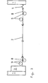
- a device for cutting uncoated or coated bodies consists in a first embodiment substantially of the bracket 1, a cutting wire 2 as a cutting member, a vibration generating device 3 and a spring mechanism as the device returning the cutting organ.
- the Fig. 1 shows a device for cutting uncoated or coated bodies in a schematic representation.
- the vibration generating device 3 At the end portions of the bracket 1 are the vibration generating device 3 and the spring mechanism in the form of a coil spring. 4
- the cutting wire 2 is coupled to the device 3 and the coil spring 4.
- the vibration generating device 3 is an eccentric coupled to a rotary drive.
- the frequency of the oscillation for the Cutting wire 2 is determined by the rotational speed of the rotary drive.
- the stroke depends on the eccentricity.
- the eccentric is known, in particular an out-of-center disc on the rotary drive. To the peripheral surface of this disc, the cutting wire 2 is coupled.
- the vibration-generating device 3 has piezo elements.
- the piezoelectric elements are connected via an AC voltage source to a low-voltage network as an energy source. Due to the reverse piezoelectric effect, the piezoelectric elements oscillate at the frequency of the AC voltage source. The stroke is determined by the piezo elements.
- the cutting wire 2 oscillates at a frequency of greater than 100 Hz and a stroke less than or equal to 3 mm in its longitudinal axis.
- the arrangement of the cutting wire 2 between the vibration generating device 3 and the coil spring 4 ensures a taut cutting wire 2.
- the tightness is ensured during the vibration of the cutting wire 2 as a reciprocating movement of the cutting wire 2 in its longitudinal axis.
- the cutting wire 2 itself consists of a metal. Furthermore, the cutting wire 2 is provided with particles of a hard material.
- the hard material is diamond, a ceramic or tungsten carbide.
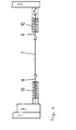
- bracket 1 In a further embodiment of the first embodiment of the bracket 1 is detachably arranged on guides 5.
- the guides 5 are connected via lockable hinges 7 with a support in the form of a base plate 6 for the uncoated or coated body for insulation and insulation spaced from each other.
- the bracket 1 and thus the cutting wire 2 relative to the base plate 6 is movable.
- the angle between the guides 5 and the base plate 6 is adjustable, so that mitres are cut.
- the Fig. 2 shows a cutting device with a device for cutting uncoated or coated bodies in a schematic representation.
- the coupling elements 8 advantageously serve for fastening the cutting wire 2 itself.
- Known hook / eye connections are used for this purpose.
- the coupling elements 8 are rod-shaped and each guided in the forced operation.
- the positive guidance consists of spaced apart in the longitudinal direction of the cutting wire 2 rollers 9, which have a circumferential groove for the coupling element 8. Between the rollers 9, the coupling element 8 is guided. The distance between the rollers 9 is either fixed or adjustable.
- the rollers 9 can be resiliently arranged in a variant so that the rollers 9 are pressed in the direction of the coupling element 8.
- the Fig. 3 shows a device for cutting with rollers 9 as positive guidance for a cutting wire 2 in a schematic representation.
- a second embodiment of the positive guidance consists of a pipe section 10 in which the respective coupling element 8 is guided.
- the cavity of the pipe section 10 is cylindrical or conical.
- the Fig. 4 shows a device for cutting with pipe sections 10 as positive guidance for the cutting wire. 2
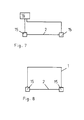
- means for cutting uncoated or coated bodies for insulation or insulation from the cutting wire 1 are the reciprocating motion as the vibration generating device and the device returning the cutting member , a drive 12 and transmission mechanisms.
- the Fig. 5 shows a device for cutting uncoated or coated bodies with a drive for the oscillating cutting member in a principal Presentation.
- the drive 12 is a rotary drive 12 in the form of a known electric motor.
- two transmission mechanisms for the rotational movement of the drive 12 are connected to the drive 12.
- These are two shafts 13, which are coupled either on both sides of the rotor of the electric motor or via a transmission to the electric motor.
- the shafts 13 are advantageously flexible shafts 13.
- the reciprocating means 11 are formed in connection with the cutting wire 2 in one embodiment as an eccentric. The eccentricity determines the stroke and the rotational speed is equivalent to the frequency of the cutting wire 2.
- the devices 11 are vibration generating devices for the cutting wire 2. With known constructions and brackets so easily a strap can be realized on the legs of the devices 11 are arranged.
- the one drive 12 and the shafts 13 ensure synchronously operating devices 11, so that the cutting wire 2 oscillates in its longitudinal axis.
- the transmission mechanisms each consist of two shafts 13a, 13b connected to one another via a gear 14.
- the gear 14 may be designed as a known bevel gear 14, so that the shafts 13a, 13b are arranged at an angle to each other.
- the Fig. 6 shows a device with a drive for a bracket in a schematic representation.
- the bracket 1 is formed to U-shaped. In the middle part are the drive 12 and the first waves 13a. In the legs of the bracket 1, the second waves 13 b are arranged.
- a device for cutting uncoated or coated bodies for insulation or insulation consists in a third embodiment essentially of the cutting wire 2 as a wire-shaped cutting member, imbalance motors 15 am Cutting wire 2 and a control device 16 for the synchronous operation of the unbalance motors 15th
- the Fig. 7 shows a device for cutting uncoated or coated bodies with unbalance motors 15 in a schematic representation.
- An unbalance motor 15 has both a drive 12 and a device 11 for a reciprocating motion.
- the unbalance motors 15 are arranged guided and / or are attached to a bracket 1.
- the unbalance motors 15 may be the guided components or guided components of the guides 5.
- the unbalance motors 15 are located at spaced-apart linear guides, which are further connected to a base / a base plate 6 for the body to be cut.
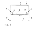
- the Fig. 8 shows a device with unbalance motors 15 on a bracket 1 in a schematic representation.
- a cutting device is realized, which is itself used for cutting bodies either by hand or in conjunction with the guides 5 on the base body / the base plate 6.
- the bracket 1 is releasably connected to guided components of the guides 5.
- the Fig. 9 shows a cutting device with a guided bracket 1 with unbalance motors 15 in a schematic representation.
- the bracket 1 is detachably arranged on guides 5.
- the guides 5 are about lockable hinges 7 with the base body / the base plate 6 for the uncoated or coated body to Isolation or insulation connected.
- the bracket 1 with the cutting wire 2 relative to the base body / the base plate 6 is movable.
- the bracket 1 is self-guided or connected to guided components of the guides 5.
- the angle between the guides 5 and the base body / the base plate 6 is adjustable, so that different cutting angles can be realized.
- the unbalance motors 15 as devices 11 for a reciprocating motion in the form of vibration generating devices are designed, for example, as coupled to rotary actuators eccentric.
- the frequency of the vibration for the cutting wire 2 is determined by the rotational speed of the rotary drive.
- the stroke depends on the eccentricity.
- the eccentric is known, in particular an out-of-center disc on the rotary drive. To the disc of the cutting wire 2 is coupled.
- the unbalance motors 15 as rotary drives have permanent-magnet motors each with a stator and a rotor with magnets.
- the permanent-magnet motors are each connected via a power converter and a device for determining the position of the rotor with the control device 16, so that the position of the rotors tunable to one another and thus a synchronous work of the unbalance motors 15 can be realized.
- the means for determining the position of the rotors is to a device for determining the position of the rotors during startup and / or during operation of the motors.
- Another embodiment of the embodiment has linear motors instead of the unbalanced motors 15. These are vibrating piezoelectric elements which deform with the frequency of an applied electric voltage and thus oscillate.
- the amplitude of the oscillations is determined by the size of the AC voltage.
- the stroke is determined by the magnitude of the AC voltage and the frequency of the oscillation by the frequency of the AC voltage.
- a long cutting wire 2 are in a further embodiment of the second and third embodiment, forced guides for the cutting wire 2 or Coupling elements 8 provided with the cutting wire 2. These are connected to the bracket 1 or the guides 5.
- the coupling elements 8 advantageously serve for fastening the cutting wire 2 itself.
- the positive guidance consists of spaced apart in the longitudinal direction of the cutting wire 2 rollers 9, which have a circumferential groove. Between the rollers 9, the coupling element 8 is guided. The distance between the rollers 9 is either fixed or adjustable.
- the rollers 9 can be resiliently arranged in a variant that the rollers 9 are pressed in the direction of the coupling element 8 (shown in the Fig. 3 ).
- this consists of a pipe section 10, in which the respective coupling element 8 is guided. (Presentation in the Fig. 4 )
- the cavity of the pipe section 10 is cylindrical or conical.
- the cutting wire 2 oscillates at a frequency of greater than 100Hz and a stroke less than or equal to 3mm in its longitudinal axis.
- the cutting wire 2 itself consists of a metal. Furthermore, this can be provided with particles of a hard material. This is advantageously diamond, a ceramic or hard metal.
- the body for insulation or insulation consists for example of a foamed plastic, organic pulp, inorganic pulp, chips containing material, composite material, natural material, polyurethane in each case from the substance itself or from a combination of these substances.
Abstract
Description
Einrichtung zum Schneiden von unbeschichteten oder beschichteten Körpern zur Isolation oder DämmungDevice for cutting uncoated or coated bodies for insulation or insulation
Die Erfindung betrifft Einrichtungen zum Schneiden von unbeschichteten oder beschichteten Körpern zur Isolation oder Dämmung mit einem draht- oder bandförmigen Schneidorgan.The invention relates to devices for cutting uncoated or coated bodies for insulation or insulation with a wire or ribbon-shaped cutting member.
Schneidgeräte mit einem hin- und herbewegbaren Rahmen mit einem Schneidorgan sind bekannt. Dabei ist der Rahmen mit dem Schneidorgan an wenigstens einen Exzenter gekoppelt.Cutters with a reciprocating frame with a cutting member are known. In this case, the frame is coupled to the cutting member to at least one eccentric.
Ein derartige Vorrichtung und ein derartiges Verfahren ist unter anderem durch die Druckschrift
Durch die Druckschrift
Der im Patentanspruch 1 angegebenen Erfindung liegt die Aufgabe zugrunde, unbeschichtete oder beschichtete Körper mit einem Schneidorgan einfach und Maß genau zu schneiden.The indicated in
Diese Aufgabe wird mit den im Patentanspruch 1 aufgeführten Merkmalen gelöst.This object is achieved with the features listed in
Die Einrichtungen zum Schneiden von unbeschichteten oder beschichteten Körpern zur Isolation oder Dämmung mit einem draht- oder bandförmigen Schneidorgan zeichnen sich insbesondere durch eine einfache Realisierung aus.The devices for cutting uncoated or coated bodies for insulation or insulation with a wire or ribbon-shaped cutting member are characterized in particular by a simple realization.
Dazu ist ein Ende des Schneidorgans an eine eine hin- und hergehende Bewegung als Vibration erzeugende Vorrichtung und das andere Ende des Schneidorgans an eine das Schneidorgan rückführende Vorrichtung gekoppelt, so dass das Schneidorgan zum Schneiden in seiner Längsachse schwingt. Weiterhin befinden sich die Vorrichtungen an einem Bügel oder an geführten Bestandteilen von Geradführungen. Mit einem Bügel ist eine leichte und einfache Handhabbarkeit gegeben. Das Schneidorgan lässt sich damit leicht per Hand oder mittels einer Führung bewegen. Im letzteren Fall ist der Bügel an geführten Bestandteilen der Führungen fest oder lösbar befestigt. Führungen sind als Geradführungen bekannt, wobei das Gleit- oder Wälzkörper-Führungen sein können. Das Schneidorgan ist günstigerweise ein Schneiddraht oder ein Schneidband. Der Abstand der Vorrichtungen bestimmt die Länge des zu schneidenden Körpers. Der Abstand ist dabei durch die beabstandet zueinander angeordneten Schenkel des Bügels oder der Geradführungen festgelegt oder festlegbar. Das Schneidorgan schwingt und vibriert durch die Bewegungen der Vorrichtungen in seiner Längsachse. Die vorhandenen Unebenheiten des Schneidorgans führen zu der Schnittwirkung der Einrichtung. Die Körper werden durch die hin- und hergehenden Bewegungen des Schneidorgans getrennt, wobei durch diese Bewegung eine Schnittfuge im Körper erzeugt wird. Die Schnittfuge entsteht günstigerweise durch eine Schleif- und/oder Schnittwirkung des Schneidorgans.For this purpose, one end of the cutting member is coupled to a reciprocating motion as a vibration generating device and the other end of the cutting member is coupled to a device returning the cutting member so that the cutting member vibrates for cutting in its longitudinal axis. Furthermore, the devices are located on a bracket or guided components of linear guides. With a bracket, a simple and easy handling is given. The cutting element can thus be easily moved by hand or by means of a guide. In the latter case, the bracket is fixedly or releasably attached to guided components of the guides. Guides are known as linear guides, wherein the sliding or rolling element guides can be. The cutting member is conveniently a cutting wire or a cutting tape. The spacing of the devices determines the length of the body to be cut. The distance is determined or fixed by the spaced-apart legs of the bracket or the linear guides. The cutting member vibrates and vibrates by the movements of the devices in its longitudinal axis. The existing unevenness of the cutting element lead to the cutting action of the device. The bodies are separated by the reciprocating movements of the cutting member, this movement creating a kerf in the body. The kerf is conveniently formed by a grinding and / or cutting action of the cutting member.
Damit sind vorteilhafterweise, unbeschichtete oder beschichtete Körper mit dem Schneidorgan einfach zu trennen. Das sind insbesondere Körper zur Wärmedämmung oder Schallisolation. Darüber hinaus können aber auch Formkörper leicht realisiert werden. Vorteilhafterweise sind das auch beschichtete Körper. Derartige Beschichtungen bestehen bekannterweise aus einem Metall oder einem Kunststoff.Thus, advantageously, uncoated or coated body with the cutting member are easy to separate. These are in particular bodies for thermal insulation or sound insulation. In addition, however, moldings can be easily realized. Advantageously, these are also coated body. Such coatings are known to consist of a metal or a plastic.
Weiterhin ist eine minimale bis keine Spanausbildung während des Schneidvorgangs zu verzeichnen.Furthermore, minimal to no chip formation is recorded during the cutting process.
Bei geschäumten Körpern verbessert sich weiterhin vorteilhafterweise die Schnittoberfläche durch partielles Aufschmelzen der oberflächennahen Schicht. Derartige Körper bestehen aus bekannten geschäumten Kunststoff.In the case of foamed bodies, the cutting surface is advantageously further improved by partial melting of the near-surface layer. Such bodies are made of known foamed plastic.
Damit lässt sich die Einrichtung vielfältig einsetzen. Insbesondere auch Körper aus nicht brennbaren geschäumten Kunststoffen, Faserstoffen und Naturstoffen, die auch eine Beschichtung aufweisen können, sind leicht schneidbar. Natürlich sind brennbare Körper davon nicht ausgenommen.Thus, the device can be used in many ways. In particular, bodies of non-combustible foamed plastics, fibers and natural materials, which may also have a coating, are easily cut. Of course, flammable bodies are not exempt from it.
Der Betrieb der wenigstens einen mechanisch schwingenden Einrichtung gewährleistet ein sicheres Schneiden der unbeschichteten oder beschichteten Körper. Der Körper zur Isolation und Dämmung besteht beispielsweise aus geschäumtem Kunststoff, organischen Faserstoffen, anorganischen Faserstoffen, Späne aufweisenden Stoffen, einem Verbundwerkstoff, Naturstoffen, Polyurethan selbst oder aus einer Kombination dieser Stoffe.The operation of the at least one mechanically oscillating device ensures a safe cutting of the uncoated or coated body. The body for insulation and insulation consists for example of foamed plastic, organic fibers, inorganic fibers, chips containing materials, a composite material, natural products, polyurethane itself or a combination of these substances.
Vorteilhafte Ausgestaltungen der Erfindung sind in den Patentansprüchen 2 bis 15 angegeben.Advantageous embodiments of the invention are specified in the
Die Vorrichtungen sind nach der Weiterbildung des Patentanspruchs 2 so ausgestaltet, dass das Schneidorgan mit einer Frequenz von größer 100Hz und einem Hub kleiner/ gleich 3mm in seiner Längsachse schwingt.The devices are designed according to the embodiment of
Die das Schneidorgan rückführende Vorrichtung ist nach der Weiterbildung des Patentanspruchs 3 ein Federmechanismus, so dass das Schneidorgan in seiner Längsachse schwingt und ein straffes Schneidorgan vorhanden ist.The device returning the cutting member is according to the embodiment of
Der Federmechanismus gewährleistet neben der Rückführung des Schneidorgans weiterhin ein straffes Schneidorgan. Im einfachsten Fall ist der Federmechanismus eine bekannte Schraubenfeder. Natürlich sind auch bekannte Federkörper einsetzbar, deren Federwirkung auf den Materialeigenschaften dieser Federkörper beruht.The spring mechanism ensures next to the return of the cutting element continues to be a taut cutting member. In the simplest case, the spring mechanism is a known coil spring. Of course, known spring body can be used, the spring action is based on the material properties of these spring body.
Die eine Vibration erzeugende Vorrichtung ist nach der Weiterbildung des Patentanspruchs 4 wenigstens ein Piezoelement ist, wobei das Piezoelement mit einer elektrischen Wechselspannungsquelle verbunden ist. Der piezoelektrische Effekt zeichnet sich dadurch aus, dass durch äußere Krafteinwirkung hervorgerufene Ladungsverschiebungen in dem Kristallgitter als Oberflächenladungen abnehmbar sind. Der piezoelektrische Effekt ist umkehrbar, so dass sich das Piezoelement bei Anlegen einer Ladung verformt. Bei Anlegen einer Wechselspannung schwingt das Piezoelement mit der Frequenz der angelegten Wechselspannung.The vibration generating device is according to the embodiment of
Das Schneidorgan ist direkt an diese Vorrichtung gekoppelt, so dass das Schneidorgan entsprechend der Deformation des Piezoelements bewegt wird. Damit schwingt das Schneidorgan als hin- und hergehende Bewegung mit der Frequenz der an das Piezoelement angelegten Wechselspannung. Der Hub wird durch die Deformation des Piezoelements bestimmt.The cutting member is coupled directly to this device, so that the cutting member is moved in accordance with the deformation of the piezoelectric element. Thus, the cutting member oscillates as a reciprocating motion with the frequency of the applied to the piezoelectric element AC voltage. The stroke is determined by the deformation of the piezo element.
Die eine Vibration erzeugende Vorrichtung ist nach der Weiterbildung des Patentanspruchs 5 ein an einen Rotationsantrieb gekoppelter Exzenter. Die Exzentrizität bestimmt bekannterweise den Hub des Schneidorgans. Die Frequenz des Schneidorgans in Form der hin- und hergehenden Bewegung ist durch die Drehzahl des Rotationsantriebs bestimmt.The vibration generating device is according to the embodiment of
Die das Schneidorgan rückführende Vorrichtung ist nach der Weiterbildung des Patentanspruchs 6 eine Vorrichtung für eine hin- und hergehende Bewegung. Das Schneidorgan ist an beabstandet zueinander angeordnete Einrichtungen für eine hin- und hergehende Bewegung und die Einrichtungen sind an wenigstens einen Antrieb gekoppelt, so dass die Einrichtungen und der Antrieb die Vorrichtungen für eine hin- und hergehende Bewegung sind. Weiterhin sind die Einrichtungen synchron arbeitende Einrichtungen, so dass das draht- oder bandförmige Schneidorgan zum Schneiden in seiner Längsachse schwingt.The device returning the cutting device is according to the embodiment of
Der Antrieb für die Vorrichtungen für eine hin- und hergehende Bewegung ist nach der Weiterbildung des Patentanspruchs 7 ein rotatorisch arbeitender Antrieb. An diesen sind zwei Übertragungsmechanismen für die Rotationsbewegung des Antriebs angeschlossen. Weiterhin ist das Schneidorgan an Exzenter an den Übertragungsmechanismen gekoppelt, so dass damit synchron arbeitende Vorrichtungen für eine hin- und hergehende Bewegung realisiert sind. Der Antrieb ist dazu beispielsweise ein bekannter Elektromotor. An den Läufer sind die Übertragungsmechanismen in Form von Wellen gekoppelt.The drive for the devices for a reciprocating movement is according to the embodiment of
Das Schneidorgan ist nach der Weiterbildung des Patentanspruchs 8 an Linearmotore als Antriebe mit Einrichtungen für eine hin- und hergehende Bewegung gekoppelt. Die Linearmotore sind synchron arbeitende Linearmotore, so dass das Schneidorgan in seiner Längsachse schwingt. Als Linearmotore können dazu günstigerweise Piezoelemente eingesetzt werden, die sich äquivalent einer angelegten elektrischen Spannung deformieren. Mittels einer Wechselspannung schwingen die Piezoelemente mit der Frequenz der Wechselspannung. Der Hub wird durch die an die Piezoelemente angelegte elektrische Spannung bestimmt.The cutting member is coupled according to the embodiment of
Das Schneidorgan ist nach der Weiterbildung des Patentanspruchs 9 an Unwuchtmotore als Antriebe mit Einrichtungen für eine hin- und hergehende Bewegung gekoppelt. Weiterhin sind das synchron arbeitende Unwuchtmotore, so dass das Schneidorgan in seiner Längsachse schwingt. Bestandteile der Unwuchtmotore sind bekannte Elektromotore.The cutting member is coupled according to the embodiment of
Die Linear- oder Unwuchtmotore sind nach der Weiterbildung des Patentanspruchs 10 geführte Bestandteile von Geradführungen. Weiterhin sind die Geradführungen an einem Grundkörper für den Körper zur Isolation oder Dämmung so angeordnet, dass das Schneidorgan gegenüber dem Grundkörper und damit den Körper zur Isolation oder Dämmung verfahrbar ist. Natürlich die Linear- oder Unwuchtmotore dazu auch an geführte Bestandteile der Geradführungen befestigt sein. Damit ist eine kompakte Einrichtung zum Schneiden von unbeschichteten oder beschichteten Körpern zur Isolation oder Dämmung mit einem draht- oder bandförmigen Schneidorgan realisiert. Die Geradführungen können auch über feststellbare Drehgelenke mit dem Grundkörper verbunden sein, so dass leicht verschiedene Geometrien schneidbar sind. Diese Schneideinrichtung ist auch mobil ausführbar, so dass eine Anwendung am Bearbeitungsort der Körper zur Isolation oder Dämmung möglich ist.The linear or imbalance motors are guided according to the embodiment of
Der Bügel mit dem Antrieb, den Linearmotoren oder den Unwuchtmotoren ist nach der Weiterbildung des Patentanspruchs 11 ein lösbarer oder fester sowie geführter Bestandteil von Geradführungen. Darüber hinaus sind die Geradführungen an einem Grundkörper für den Körper zur Isolation oder Dämmung so angeordnet, dass der Bügel und damit das Schneidorgan gegenüber dem Grundkörper und somit den Körper zur Isolation oder Dämmung verfahrbar ist. Dazu ist der Bügel selbst geführt oder an geführte Bestandteile der Geradführungen befestigt.The bracket with the drive, the linear motors or the unbalance motors is according to the embodiment of
Die Unwuchtmotore nach der Weiterbildung des Patentanspruchs 12 in Form von permanenterregten Motoren besitzen bekannterweise jeweils einen Stator und einen Rotor mit Magneten. Weiterhin sind die permanent erregten Motore jeweils über einen Stromrichter und einer Einrichtung zur Ermittlung der Lage des Rotors mit einer Steuereinrichtung verbunden, so dass die Lage der Rotoren aufeinander abstimmbar und damit eine synchrone Arbeit der Unwuchtmotore realisierbar ist.The unbalance motors according to the embodiment of
Permanent erregte Motore sind bekannte permanent erregte Synchronmaschinen oder bürstenlose Gleichstrommotore, die aus dem Stator und dem Rotor mit Magneten bestehen. Die einzelnen Phasen des Stators sind im Stern oder Dreieck verschaltet. Der Motor wird mit einem Stromrichter betrieben. Mittels der Steuereinrichtung werden die Rotorlage ermittelt und die einzelnen Phasen bestromt.Permanently energized motors are known permanent magnet synchronous machines or brushless DC motors, which consist of the stator and the rotor with magnets. The individual phases of the stator are connected in star or delta. The engine is operated with a power converter. By means of the control device, the rotor position are determined and energized the individual phases.
Die Rotorlage wird dazu mittels Sensoren oder sensorlos detektiert. Sensoren sind dazu beispielsweise bekannte Hallsensoren. Sensorlos wird in einer ersten Variante die durch Bewegung in den Phasen induzierte Spannung detektiert. In einer zweiten Variante werden die Ständerinduktivitäten variiert, wobei die Sättigung der Ständerinduktivität durch das Rotorfeld der Permanentmagnete und das stromverursachte Statorfeld beeinflusst wird.The rotor position is detected by means of sensors or sensorless. Sensors are, for example, known Hall sensors. Sensorless, the voltage induced by movement in the phases is detected in a first variant. In a second variant, the stator inductances are varied, the saturation of the stator inductance being influenced by the rotor field of the permanent magnets and the current-induced stator field.
Günstigerweise ist die Einrichtung zur Ermittlung der Lage der Rotoren nach der Weiterbildung des Patentanspruchs 13 eine Einrichtung zur Ermittlung der Lage der Rotoren im Anlauf und/oder während des Betriebs der Motore. Damit ist ein synchroner Betrieb der Unwuchtmotore leicht realisierbar.Conveniently, the means for determining the position of the rotors after the Development of
Die Endenbereiche des Schneidorgans oder an den Enden des Schneidorgans angeordnete Koppelelemente sind nach der Weiterbildung des Patentanspruchs 14 in Zwangsführungen geführt. Diese verhindern das Schwingen des Schneidorgans quer zu dessen Längsachse. Das ist insbesondere bei langen Schneidorganen vorteilhaft, so dass auch lange Schnitte mit der Einrichtung realisierbar sind. Zwangsführungen sind dazu beispielsweise entweder in Längsrichtung beabstandet angeordnete und im Umfang jeweils eine Nut aufweisende Rollen oder Rohrstücke.The end portions of the cutting member or arranged at the ends of the cutting element coupling elements are guided according to the embodiment of
Nach der Weiterbildung des Patentanspruchs 15 ist das Schneidorgan ein aus einem Metall oder einer Keramik bestehendes Schneidorgan. Die Breite der Schnittfuge ist durch den Durchmesser des drahtförmigen Schneidorgans oder der Dicke des bandförmigen Schneidorgans bestimmt.According to the embodiment of
Das Schneidorgan kann dabei vorteilhafterweise Partikel aus einem Hartstoff aufweisen. Damit wird die Rauheit der Oberfläche des Schneidorgans und daraus folgernd die Schnittwirkung wesentlich erhöht. Günstigerweise können die Partikel aus Diamant, einer Keramik oder Hartmetall bestehen.The cutting member may advantageously comprise particles of a hard material. Thus, the roughness of the surface of the cutting member and, consequently, the cutting action is substantially increased. Conveniently, the particles may consist of diamond, a ceramic or hard metal.
Das drahtförmige Schneidorgan kann darüber hinaus auch aus mehreren miteinander verdrillten Drähten bestehen.The wire-shaped cutting member may also consist of several twisted together wires.
Ausführungsbeispiel der Erfindung sind in den Zeichnungen jeweils prinzipiell dargestellt und werden im Folgenden näher beschrieben.Embodiment of the invention are illustrated in principle in the drawings and will be described in more detail below.
Es zeigen:
- Fig. 1
- eine Einrichtung zum Schneiden von unbeschichteten oder beschichteten Körpern,
- Fig. 2
- eine Schneidvorrichtung mit einer Einrichtung zum Schneiden von unbeschichteten oder beschichteten Körpern,
- Fig. 3
- eine Einrichtung zum Schneiden mit Rollen als Zwangsführung für einen Schneiddraht,
- Fig. 4
- eine Einrichtung zum Schneiden mit Rohrstücken als Zwangsführung für den Schneiddraht,
- Fig. 5
- eine Einrichtung zum Schneiden von unbeschichteten oder beschichteten Körpern mit einem Antrieb für das schwingende Schneidorgan,
- Fig. 6
- eine Einrichtung mit einem Antrieb für einen Bügel,
- Fig. 7
- eine Einrichtung zum Schneiden von unbeschichteten oder beschichteten Körpern mit Linear- oder Unwuchtmotoren,
- Fig. 8
- eine Einrichtung mit Linear- oder Unwuchtmotoren an einem Bügel und
- Fig. 9
- eine Schneidvorrichtung mit einem geführten Bügel mit einer Einrichtung.
- Fig. 1
- a device for cutting uncoated or coated bodies,
- Fig. 2
- a cutting device with a device for cutting uncoated or coated bodies,
- Fig. 3
- a device for cutting with rollers as forced guidance for a Cutting wire,
- Fig. 4
- a device for cutting with pipe sections as positive guidance for the cutting wire,
- Fig. 5
- a device for cutting uncoated or coated bodies with a drive for the oscillating cutting member,
- Fig. 6
- a device with a drive for a bracket,
- Fig. 7
- a device for cutting uncoated or coated bodies with linear or unbalanced motors,
- Fig. 8
- a device with linear or unbalance motors on a bracket and
- Fig. 9
- a cutting device with a guided bracket with a device.
Eine Einrichtung zum Schneiden von unbeschichteten oder beschichteten Körpern zur Isolation und Dämmung mit einem draht- oder bandförmigen Schneidorgan besteht im Wesentlichen aus einer eine hin- und hergehende Bewegung als Vibration erzeugenden Vorrichtung, einer das Schneidorgan rückführenden Vorrichtung und einem Bügel 1 und/oder geführten Bestandteilen von Geradführungen.A device for cutting uncoated or coated bodies for insulation and insulation with a wire or ribbon-shaped cutting member consists essentially of a reciprocating motion as a vibration generating device, a device returning the cutting organ and a
Eine Einrichtung zum Schneiden von unbeschichteten oder beschichteten Körpern besteht in einem ersten Ausführungsbeispiel im Wesentlichen aus dem Bügel 1, einem Schneiddraht 2 als Schneidorgan, einer eine Vibration erzeugenden Vorrichtung 3 und einem Federmechanismus als die das Schneidorgan rückführende Vorrichtung.A device for cutting uncoated or coated bodies consists in a first embodiment substantially of the
Die
An den Endenbereichen des Bügels 1 befinden sich die Vibrationen erzeugende Vorrichtung 3 und der Federmechanismus in Form einer Schraubenfeder 4.At the end portions of the
Der Schneiddraht 2 ist an die Vorrichtung 3 und die Schraubenfeder 4 gekoppelt. In einer ersten Ausführungsform ist die Vibrationen erzeugende Vorrichtung 3 ein an einen Rotationsantrieb gekoppelter Exzenter. Die Frequenz der Schwingung für den Schneiddraht 2 wird durch die Drehzahl des Rotationsantriebs bestimmt. Der Hub ist von der Exzentrizität abhängig. Der Exzenter ist bekannterweise insbesondere eine außer mittig angeordnete Scheibe am Rotationsantrieb. An die Umfangsfläche dieser Scheibe ist der Schneiddraht 2 gekoppelt.The
In einer zweiten Ausführungsform weist die Vibrationen erzeugende Vorrichtung 3 Piezoelemente auf. Die Piezoelemente sind über eine Wechselspannungsquelle mit einem Niederspannungsnetz als Energiequelle verbunden. Durch den umgekehrten piezoelektrischen Effekt schwingen die Piezoelemente mit der Frequenz der Wechselspannungsquelle. Der Hub ist durch die Piezoelemente bestimmt.In a second embodiment, the vibration-generating
Günstigerweise schwingt der Schneiddraht 2 mit einer Frequenz von größer 100 Hz und einem Hub kleiner/gleich 3 mm in seiner Längsachse.Conveniently, the
Die Anordnung des Schneiddrahtes 2 zwischen der die Vibration erzeugenden Vorrichtung 3 und der Schraubenfeder 4 sichert einen straffen Schneiddraht 2. Die Straffheit ist dabei auch während der Vibration des Schneiddrahtes 2 als hin- und hergehende Bewegung des Schneiddrahtes 2 in dessen Längsachse gewährleistet.The arrangement of the
Der Schneiddraht 2 selbst besteht aus einem Metall. Weiterhin ist der Schneiddraht 2 mit Partikeln aus einem Hartstoff versehen. Der Hartstoff ist dazu Diamant, eine Keramik oder Hartmetall.The
In einer weiteren Ausführungsform des ersten Ausführungsbeispiels ist der Bügel 1 an Führungen 5 lösbar angeordnet. Die Führungen 5 sind über feststellbare Drehgelenke 7 mit einem Träger in Form einer Grundplatte 6 für den unbeschichteten oder beschichteten Körper zur Isolation und Dämmung beabstandet zueinander verbunden. Damit ist der Bügel 1 und somit der Schneiddraht 2 gegenüber der Grundplatte 6 verfahrbar. Weiterhin ist der Winkel zwischen den Führungen 5 und der Grundplatte 6 einstellbar, so dass auch Gehrungen schneidbar sind.In a further embodiment of the first embodiment of the
Die
Bei einem langen Schneiddraht 2 sind in einer weiteren Ausführungsform Zwangsführungen für den Schneiddraht 2 oder Koppelelemente 8 mit dem Schneiddraht 2 vorgesehen. Diese sind mit dem Bügel 1 verbunden.In a
Die Koppelelemente 8 dienen gleichzeitig vorteilhafterweise zur Befestigung des Schneiddrahtes 2 selbst. Dazu werden bekannte Haken/Ösen-Verbindungen verwendet. Die Koppelelemente 8 sind stangenförmig ausgebildet und jeweils in der Zwangsführung geführt.At the same time, the
In einer ersten Ausführungsform der Zwangsführung besteht diese aus in Längsrichtung des Schneiddrahtes 2 beabstandet zueinander angeordneten Rollen 9, die eine umlaufende Nut für das Koppelelement 8 besitzen. Zwischen den Rollen 9 ist das Koppelelement 8 geführt. Der Abstand der Rollen 9 ist entweder fest oder einstellbar. Die Rollen 9 können in einer Variante federnd so angeordnet werden, dass die Rollen 9 in Richtung Koppelelement 8 gedrückt werden.In a first embodiment, the positive guidance consists of spaced apart in the longitudinal direction of the
Die
In einer zweiten Ausführungsform der Zwangsführung besteht diese aus einem Rohrstück 10, in dem das jeweilige Koppelelement 8 geführt ist. Der Hohlraum des Rohrstücks 10 ist zylindrisch oder konisch ausgebildet.In a second embodiment of the positive guidance consists of a
Die
In einem zweiten Ausführungsbeispiel besteht eine Einrichtung zum Schneiden von unbeschichteten oder beschichteten Körpern zur Isolation oder Dämmung aus dem Schneiddraht 1, Einrichtungen 11 für eine hin- und hergehende Bewegung als die eine hin- und hergehende Bewegung als Vibration erzeugenden Vorrichtung und die das Schneidorgan rückführenden Vorrichtung, einem Antrieb 12 und Übertragungsmechanismen.In a second embodiment, means for cutting uncoated or coated bodies for insulation or insulation from the
Die
Der Antrieb 12 ist ein rotatorisch arbeitender Antrieb 12 in Form eines bekannten Elektromotors. An den Antrieb 12 sind zwei Übertragungsmechanismen für die Rotationsbewegung des Antriebs 12 angeschlossen. Das sind zwei Wellen 13, die entweder beidseitig an den Läufer des Elektromotors oder über ein Getriebe an den Elektromotor angekoppelt sind. Die Wellen 13 sind vorteilhafterweise biegsame Wellen 13. Die Einrichtungen 11 für die hin- und hergehende Bewegung sind in Verbindung mit dem Schneiddraht 2 in einer Ausführungsform als Exzenter ausgebildet. Die Exzentrizität bestimmt den Hub und die Drehzahl ist äquivalent der Frequenz des Schneiddrahts 2. Die Einrichtungen 11 sind Vibrationen erzeugende Vorrichtungen für den Schneiddraht 2. Mit bekannten Konstruktionen und Halterungen ist damit leicht ein Bügel realisierbar, an dessen Schenkeln die Einrichtungen 11 angeordnet sind.The
Der eine Antrieb 12 und die Wellen 13 gewährleisten synchron arbeitende Einrichtungen 11, so dass der Schneiddraht 2 in seiner Längsachse schwingt.The one
In einer Ausführungsform bestehen die Übertragungsmechanismen jeweils aus zwei über ein Getriebe 14 miteinander verbundenen Wellen 13a, 13b. Das Getriebe 14 kann als bekanntes Kegelradgetriebe 14 ausgeführt sein, so dass die Wellen 13a, 13b winklig zueinander anordenbar sind.In one embodiment, the transmission mechanisms each consist of two
Die
Der Bügel 1 ist dazu U-förmig ausgebildet. Im Mittelteil befinden sich der Antrieb 12 und die ersten Wellen 13a. In den Schenkeln des Bügels 1 sind die zweiten Wellen 13b angeordnet.The
Eine Einrichtung zum Schneiden von unbeschichteten oder beschichteten Körpern zur Isolation oder Dämmung besteht in einem dritten Ausführungsbeispiel im Wesentlichen aus dem Schneiddraht 2 als drahtförmiges Schneidorgan, Unwuchtmotoren 15 am Schneiddraht 2 und einer Steuereinrichtung 16 zur synchronen Arbeitsweise der Unwuchtmotore 15.A device for cutting uncoated or coated bodies for insulation or insulation consists in a third embodiment essentially of the
Die
Ein Unwuchtmotor 15 besitzt sowohl einen Antrieb 12 als auch eine Einrichtung 11 für eine hin- und hergehende Bewegung.An
Zum Schneiden unbeschichteter oder beschichteter Körper sind die Unwuchtmotore 15 geführt angeordnet und/oder sind an einem Bügel 1 befestigt. Im ersteren Fall können die Unwuchtmotore 15 die geführten Bestandteile oder an geführten Bestandteilen der Führungen 5 sein.For cutting uncoated or coated body, the
In einer Ausführungsform befinden sich die Unwuchtmotore 15 an beabstandet zueinander angeordneten Geradführungen, die weiterhin mit einem Grundkörper/einer Grundplatte 6 für den zu schneidenden Körper verbunden sind.In one embodiment, the
Die
In einer weiteren Ausführungsform mit den Unwuchtmotoren 15 an dem Bügel 1 ist eine Schneideinrichtung realisiert, die selbst zum Schneiden von Körpern entweder per Hand oder in Verbindung mit den Führungen 5 an dem Grundkörper/der Grundplatte 6 einsetzbar ist. Dazu ist der Bügel 1 lösbar mit geführten Bestandteilen der Führungen 5 verbunden.In a further embodiment with the
Die
In Fortführung der weiteren Ausführungsform ist der Bügel 1 an Führungen 5 lösbar angeordnet. Die Führungen 5 sind über feststellbare Drehgelenke 7 mit dem Grundkörper/der Grundplatte 6 für den unbeschichteten oder beschichteten Körper zur Isolation oder Dämmung verbunden. Damit ist der Bügel 1 mit dem Schneiddraht 2 gegenüber dem Grundkörper/der Grundplatte 6 verfahrbar. Dazu ist der Bügel 1 selbst geführt oder mit geführten Bestandteilen der Führungen 5 verbunden. Weiterhin ist der Winkel zwischen den Führungen 5 und dem Grundkörper/der Grundplatte 6 einstellbar, so dass verschiedene Schnittwinkel realisierbar sind.In continuation of the further embodiment, the
Die Unwuchtmotore 15 als Einrichtungen 11 für eine hin- und hergehende Bewegung in Form von Vibrationen erzeugenden Vorrichtungen sind beispielsweise als an Rotationsantriebe gekoppelte Exzenter ausgeführt. Die Frequenz der Schwingung für den Schneiddraht 2 wird durch die Drehzahl des Rotationsantriebs bestimmt. Der Hub ist von der Exzentrizität abhängig. Der Exzenter ist bekannterweise insbesondere eine außer mittig angeordnete Scheibe am Rotationsantrieb. An die Scheibe ist der Schneiddraht 2 gekoppelt.The
Die Unwuchtmotore 15 als Rotationsantriebe besitzen permanenterregte Motore jeweils mit einem Stator und einem Rotor mit Magneten. Die permanenterregten Motore sind jeweils über einen Stromrichter und einer Einrichtung zur Ermittlung der Lage des Rotors mit der Steuereinrichtung 16 verbunden, so dass die Lage der Rotoren aufeinander abstimmbar und damit eine synchrone Arbeit der Unwuchtmotore 15 realisierbar ist. Die Einrichtung zur Ermittlung der Lage der Rotoren ist dazu eine Einrichtung zur Ermittlung der Lage der Rotoren im Anlauf und/oder während des Betriebs der Motore.The
Eine weitere Ausführungsform des Ausführungsbeispiels besitzt Linearmotore anstelle der Unwuchtmotore 15. Das sind schwingende Piezoelemente, die sich mit der Frequenz einer angelegten elektrischen Spannung deformieren und damit schwingen. Die Amplitude der Schwingungen wird durch die Größe der Wechselspannung bestimmt. Somit wird der Hub durch die Größe der Wechselspannung und die Frequenz der Schwingung durch die Frequenz der Wechselspannung bestimmt.Another embodiment of the embodiment has linear motors instead of the
Bei einem langen Schneiddraht 2 sind in einer weiteren Ausführungsform des zweiten und dritten Ausführungsbeispiels Zwangsführungen für den Schneiddraht 2 oder Koppelelemente 8 mit dem Schneiddraht 2 vorgesehen. Diese sind mit dem Bügel 1 oder den Führungen 5 verbunden.In a
Die Koppelelemente 8 dienen gleichzeitig vorteilhafterweise zur Befestigung des Schneiddrahtes 2 selbst.At the same time, the
In einer Ausführungsform der Zwangsführung besteht diese aus in Längsrichtung des Schneiddrahtes 2 beabstandet zueinander angeordneten Rollen 9, die eine umlaufende Nut besitzen. Zwischen den Rollen 9 ist das Koppelelement 8 geführt. Der Abstand der Rollen 9 ist entweder fest oder einstellbar. Die Rollen 9 können in einer Variante federnd so angeordnet werden, dass die Rollen 9 in Richtung Koppelelement 8 gedrückt werden (Darstellung in der
In einer weiteren Ausführungsform der Zwangsführung besteht diese aus einem Rohrstück 10, in dem das jeweilige Koppelelement 8 geführt ist. (Darstellung in der
Günstigerweise schwingt der Schneiddraht 2 mit einer Frequenz von größer 100Hz und einem Hub kleiner/gleich 3mm in seiner Längsachse.Conveniently, the
Der Schneiddraht 2 selbst besteht aus einem Metall. Weiterhin kann dieser mit Partikeln aus einem Hartstoff versehen sein. Dieser ist dazu vorteilhafterweise Diamant, eine Keramik oder Hartmetall.The
Der Körper zur Isolation oder Dämmung besteht beispielsweise aus einem geschäumten Kunststoff, organischen Faserstoff, anorganischen Faserstoff, Späne aufweisenden Stoff, Verbundwerkstoff, Naturstoff, Polyurethan jeweils aus dem Stoff selbst oder aus einer Kombination dieser Stoffe.The body for insulation or insulation consists for example of a foamed plastic, organic pulp, inorganic pulp, chips containing material, composite material, natural material, polyurethane in each case from the substance itself or from a combination of these substances.
Claims (15)
Applications Claiming Priority (3)
| Application Number | Priority Date | Filing Date | Title |
|---|---|---|---|
| DE102010023842 | 2010-06-10 | ||
| DE201020009080 DE202010009080U1 (en) | 2010-06-10 | 2010-06-10 | Device for cutting uncoated or coated bodies with a cutting member |
| DE202010016034U DE202010016034U1 (en) | 2010-11-27 | 2010-11-27 | Device for cutting uncoated or coated bodies for insulation or insulation |
Publications (1)
| Publication Number | Publication Date |
|---|---|
| EP2394802A1 true EP2394802A1 (en) | 2011-12-14 |
Family
ID=44562661
Family Applications (1)
| Application Number | Title | Priority Date | Filing Date |
|---|---|---|---|
| EP11400032A Withdrawn EP2394802A1 (en) | 2010-06-10 | 2011-06-04 | Device for cutting uncoated or coated bodies for insulation or dampening |
Country Status (2)
| Country | Link |
|---|---|
| EP (1) | EP2394802A1 (en) |
| DE (1) | DE102011103550A1 (en) |
Cited By (4)
| Publication number | Priority date | Publication date | Assignee | Title |
|---|---|---|---|---|
| CN103192418A (en) * | 2013-03-06 | 2013-07-10 | 江太炎 | Household electric filament and chip cutting machine |
| FR3057195A1 (en) * | 2016-10-11 | 2018-04-13 | Sodeva Tds | DEVICE FOR ULTRASOUND VIBRATION OF A VIBRANT WIRE FOR CUTTING INDUSTRIAL PRODUCTS, IN PARTICULAR FOOD PRODUCTS |
| CN109894683A (en) * | 2019-03-29 | 2019-06-18 | 奥美森智能装备股份有限公司 | A kind of new-type fracture pipe racking device |
| EP2900527B1 (en) * | 2012-09-28 | 2020-11-11 | Robert Bosch GmbH | Method for separating wiper strips, in particular of dual extruded wiper strips |
Families Citing this family (1)
| Publication number | Priority date | Publication date | Assignee | Title |
|---|---|---|---|---|
| DE102015204417A1 (en) * | 2015-03-12 | 2016-09-15 | Audi Ag | Cutting unit with a blade for separating at least one fiber, in particular for the production of fiber preforms |
Citations (6)
| Publication number | Priority date | Publication date | Assignee | Title |
|---|---|---|---|---|
| DE7520528U (en) * | 1976-01-08 | Arthaud, Jacques, Massy (Frankreich) | Saw attachment for multi-purpose machine | |
| DE3213900A1 (en) | 1982-04-15 | 1983-10-27 | Walter 8135 Söcking Brüser | Process for splitting rigid and flexible foam slabs into sheets, in particular polystyrene and polyurethane, also with other splitting methods of sheets |
| EP0124001A2 (en) * | 1983-05-02 | 1984-11-07 | Bernhard Schwarz | Cutting machine for plastic plates or blocks |
| EP0770459B1 (en) | 1995-09-04 | 2001-02-28 | Kurtz Altaussee GmbH | Apparatus and Method for cutting with cutting frames moving in parallel |
| US20090283214A1 (en) * | 2008-05-16 | 2009-11-19 | Jack Richard Nelson | Device and method for separating adhesive |
| US20100028516A1 (en) * | 2008-07-31 | 2010-02-04 | Kraft Foods Holding, Inc. | Production of cookies having large particulates using ultrasonic wirecutting |
-
2011
- 2011-06-04 DE DE201110103550 patent/DE102011103550A1/en not_active Withdrawn
- 2011-06-04 EP EP11400032A patent/EP2394802A1/en not_active Withdrawn
Patent Citations (6)
| Publication number | Priority date | Publication date | Assignee | Title |
|---|---|---|---|---|
| DE7520528U (en) * | 1976-01-08 | Arthaud, Jacques, Massy (Frankreich) | Saw attachment for multi-purpose machine | |
| DE3213900A1 (en) | 1982-04-15 | 1983-10-27 | Walter 8135 Söcking Brüser | Process for splitting rigid and flexible foam slabs into sheets, in particular polystyrene and polyurethane, also with other splitting methods of sheets |
| EP0124001A2 (en) * | 1983-05-02 | 1984-11-07 | Bernhard Schwarz | Cutting machine for plastic plates or blocks |
| EP0770459B1 (en) | 1995-09-04 | 2001-02-28 | Kurtz Altaussee GmbH | Apparatus and Method for cutting with cutting frames moving in parallel |
| US20090283214A1 (en) * | 2008-05-16 | 2009-11-19 | Jack Richard Nelson | Device and method for separating adhesive |
| US20100028516A1 (en) * | 2008-07-31 | 2010-02-04 | Kraft Foods Holding, Inc. | Production of cookies having large particulates using ultrasonic wirecutting |
Cited By (6)
| Publication number | Priority date | Publication date | Assignee | Title |
|---|---|---|---|---|
| EP2900527B1 (en) * | 2012-09-28 | 2020-11-11 | Robert Bosch GmbH | Method for separating wiper strips, in particular of dual extruded wiper strips |
| CN103192418A (en) * | 2013-03-06 | 2013-07-10 | 江太炎 | Household electric filament and chip cutting machine |
| CN103192418B (en) * | 2013-03-06 | 2015-01-07 | 江太炎 | Household electric filament and chip cutting machine |
| FR3057195A1 (en) * | 2016-10-11 | 2018-04-13 | Sodeva Tds | DEVICE FOR ULTRASOUND VIBRATION OF A VIBRANT WIRE FOR CUTTING INDUSTRIAL PRODUCTS, IN PARTICULAR FOOD PRODUCTS |
| CN109894683A (en) * | 2019-03-29 | 2019-06-18 | 奥美森智能装备股份有限公司 | A kind of new-type fracture pipe racking device |
| CN109894683B (en) * | 2019-03-29 | 2024-04-12 | 奥美森智能装备股份有限公司 | Novel broken material calandria device |
Also Published As
| Publication number | Publication date |
|---|---|
| DE102011103550A1 (en) | 2011-12-15 |
Similar Documents
| Publication | Publication Date | Title |
|---|---|---|
| EP2394802A1 (en) | Device for cutting uncoated or coated bodies for insulation or dampening | |
| EP1641602B1 (en) | Small electrical appliance comprising an electric motor for generating an oscillating displacement | |
| DE102010022812B4 (en) | ultrasonic motor | |
| WO2008040684A1 (en) | Electric machine | |
| EP2257415B1 (en) | Concrete block finisher, having harmonic vibration by means of shape excitation and method for shaping and compacting concrete mixtures | |
| DE202015001305U1 (en) | Oscillating arrangement for a vibrating table or a screening device | |
| EP1816727A3 (en) | Electric motor | |
| DE202017100736U1 (en) | Ultrasonic hand drill | |
| DE4203434A1 (en) | METHOD AND DEVICE FOR GRINDING WORKPIECES | |
| DE2530045A1 (en) | ELECTRIC MOTOR | |
| WO2021104765A1 (en) | Rotor for an electric machine and method for producing a rotor | |
| EP1722036A2 (en) | Ground compacting machine | |
| DE202014009997U1 (en) | Double helical spline vibration mechanism and compacting machine having vibratory mechanism | |
| DE202013008945U1 (en) | Core hole drill | |
| DE19909913B4 (en) | Electromechanical drive device | |
| DE19916378A1 (en) | Internal vibrator with variable vibration amplitude | |
| WO2018146531A1 (en) | Handheld ultrasonic drilling machine | |
| DE202010016034U1 (en) | Device for cutting uncoated or coated bodies for insulation or insulation | |
| EP1130756A2 (en) | Piezoelectric actuator | |
| DE102013219764A1 (en) | machine tool | |
| EP1672769A3 (en) | Actuating device for vehicle components | |
| EP1777068A3 (en) | Direct drive of a printing machine | |
| WO2020144067A1 (en) | Electric motor | |
| EP2781269A1 (en) | Vibration generator, especially for a construction machine | |
| EP3165290B1 (en) | Vibration generator and method for inserting a pile element into the ground |
Legal Events
| Date | Code | Title | Description |
|---|---|---|---|
| AK | Designated contracting states |
Kind code of ref document: A1 Designated state(s): AL AT BE BG CH CY CZ DE DK EE ES FI FR GB GR HR HU IE IS IT LI LT LU LV MC MK MT NL NO PL PT RO RS SE SI SK SM TR |
|
| AX | Request for extension of the european patent |
Extension state: BA ME |
|
| PUAI | Public reference made under article 153(3) epc to a published international application that has entered the european phase |
Free format text: ORIGINAL CODE: 0009012 |
|
| 17P | Request for examination filed |
Effective date: 20120612 |
|
| STAA | Information on the status of an ep patent application or granted ep patent |
Free format text: STATUS: THE APPLICATION IS DEEMED TO BE WITHDRAWN |
|
| 18D | Application deemed to be withdrawn |
Effective date: 20140103 |