EP2394765B1 - Perceuse à percussion - Google Patents
Perceuse à percussion Download PDFInfo
- Publication number
- EP2394765B1 EP2394765B1 EP20100165864 EP10165864A EP2394765B1 EP 2394765 B1 EP2394765 B1 EP 2394765B1 EP 20100165864 EP20100165864 EP 20100165864 EP 10165864 A EP10165864 A EP 10165864A EP 2394765 B1 EP2394765 B1 EP 2394765B1
- Authority
- EP
- European Patent Office
- Prior art keywords
- housing
- shaft
- bevel gear
- disc
- unit
- Prior art date
- Legal status (The legal status is an assumption and is not a legal conclusion. Google has not performed a legal analysis and makes no representation as to the accuracy of the status listed.)
- Not-in-force
Links
Images


Classifications
-
- B—PERFORMING OPERATIONS; TRANSPORTING
- B25—HAND TOOLS; PORTABLE POWER-DRIVEN TOOLS; MANIPULATORS
- B25D—PERCUSSIVE TOOLS
- B25D11/00—Portable percussive tools with electromotor or other motor drive
- B25D11/06—Means for driving the impulse member
- B25D11/10—Means for driving the impulse member comprising a cam mechanism
- B25D11/102—Means for driving the impulse member comprising a cam mechanism the rotating axis of the cam member being coaxial with the axis of the tool
- B25D11/106—Means for driving the impulse member comprising a cam mechanism the rotating axis of the cam member being coaxial with the axis of the tool cam member and cam follower having the same shape
-
- B—PERFORMING OPERATIONS; TRANSPORTING
- B23—MACHINE TOOLS; METAL-WORKING NOT OTHERWISE PROVIDED FOR
- B23Q—DETAILS, COMPONENTS, OR ACCESSORIES FOR MACHINE TOOLS, e.g. ARRANGEMENTS FOR COPYING OR CONTROLLING; MACHINE TOOLS IN GENERAL CHARACTERISED BY THE CONSTRUCTION OF PARTICULAR DETAILS OR COMPONENTS; COMBINATIONS OR ASSOCIATIONS OF METAL-WORKING MACHINES, NOT DIRECTED TO A PARTICULAR RESULT
- B23Q5/00—Driving or feeding mechanisms; Control arrangements therefor
- B23Q5/02—Driving main working members
- B23Q5/04—Driving main working members rotary shafts, e.g. working-spindles
- B23Q5/043—Accessories for spindle drives
- B23Q5/045—Angle drives
-
- B—PERFORMING OPERATIONS; TRANSPORTING
- B25—HAND TOOLS; PORTABLE POWER-DRIVEN TOOLS; MANIPULATORS
- B25D—PERCUSSIVE TOOLS
- B25D2211/00—Details of portable percussive tools with electromotor or other motor drive
- B25D2211/003—Crossed drill and motor spindles
-
- B—PERFORMING OPERATIONS; TRANSPORTING
- B25—HAND TOOLS; PORTABLE POWER-DRIVEN TOOLS; MANIPULATORS
- B25D—PERCUSSIVE TOOLS
- B25D2250/00—General details of portable percussive tools; Components used in portable percussive tools
- B25D2250/121—Housing details
Definitions
- the present invention relates to a percussion drill, comprising a drive device equipped with a drive motor with a rotatably driven first axis, a housing having a unit which can be placed on the drive means, with a further axis, which is equipped with a receptacle for a drill and to which the rotational movement of the first axis and the striking axial movement generated by a beating device is transferable, which beating device is arranged in the unit and the rotational movement of the first axis is transferable via a transmission to the further axis, and which beating device of a first disc-shaped Wheel, which is held stationary in the housing, and a second disc-shaped wheel, which is fixed on the further axis, is formed, and that the mutually facing end faces of the two disc-shaped wheels each with a substantially en are provided in the radial direction toothing, wherein the first axis and the further axis are aligned in the patch on the drive means state of the unit substantially at right angles to each other.
- Percussion drills are known in many ways. They are used to drill holes in masonry or concrete works, these impact drills are hand-operated machines. The usual impact drills have in the axial direction of the drill and consequently the hole to be mounted on a large length, which is why it is necessary that in the axial direction of the hole to be mounted a relatively large space is available. In the absence of such a clearance, it becomes difficult, if not impossible, to be able to attach the corresponding bore with such a percussion drill.
- impact drills which are provided with an essay, in which the drill with respect.
- the longitudinal alignment in an angled position preferably can be used at right angles.
- Such a device is for example from the DE-A-3439475 known.
- an angled attachment is placed, with which in addition to the rotary driving of the drill and the beating axial movement is deflected to the drill.
- the full impact can not be transferred to the drill. Due to the elasticity of the impact transfer means some of impact energy is lost.
- the production of such a design of a percussion drill is relatively complex and associated with high costs.
- JP 2004 216 511 A is a percussion drill according to the preamble of independent claim 1 described.
- the object of the present invention is thus to make a percussion drill with angled drill so that the best possible impact effect is achieved and the production and assembly can be achieved in a simple manner and cost.
- the solution of this object is achieved in that the housing of the unit is formed of two halves, which are detachably connected to each other, and that the axial movement of the further axis away from the first disc-shaped wheel is limited by a stop, which stop arranged by a housing Shoulder is formed, on which the provided with a toothing end face opposite end face of the second disc-shaped wheel can be supported.
- this embodiment it is achieved that the beating movement generated by the direction of impact can be transmitted directly to the drill without deflection, whereby the energy loss can be reduced to an absolute minimum and the efficiency of the percussion drill can be optimally maintained.
- the height in the axial direction of the drill can be kept very low by this embodiment of the invention. As a result, the application area can be increased even in tight spaces.
- the unit has a housing, which is formed from two halves, which are detachably connected to each other, whereby in particular a simple assembly of this unit can be achieved.
- the axial movement of the further axis away from the first disk-shaped wheel can be limited by a stop which is formed by a shoulder arranged on the housing, on which the end face of the second disk-shaped wheel opposite the toothed end face can be supported.
- the unit can be mounted in a simple manner.
- the unit is connected in an advantageous manner by means of screwing to the drive device, which can be achieved with little effort.
- the transmission consists of a first bevel gear, which is connected to the first axis, and a second bevel gear, which is rotatably mounted on the further axis, which two bevel gears mesh with each other, resulting in a very simple structure.
- the second bevel gear is held stationary and rotatable in the housing.
- the further axis is rotationally fixed and arranged axially displaceable in the second bevel gear, whereby an optimal transmission of the rotation is obtained.
- the second bevel gear is provided with an axial bore, the surface of which is provided with axially extending ribs and grooves, and the surface of the further axis is provided with corresponding, axially extending grooves and ribs, which optimally fulfills the desired properties.
- the further axis is held by an upper radial bearing and a lower radial bearing in the housing, resulting in a stable mounting of the other axis in the housing.
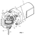
- the impact drill according to the invention consists in a known manner of a drive device 1, in which a drive motor in the form of an electric motor is used, which is not shown, and with which a first axis 2 can be driven to rotate in a known manner.
- This drive device 1 has an end face 3, from which protrudes the first axis 2, on which end face 3 screws 4 are attached.
- a unit 5 can be screwed, which has a housing 6 which consists of two halves 7 and 8 (FIG. Fig. 4 ) is formed. In the embodiment shown here, one half 8 of the housing 6 is omitted for reasons of visibility.
- a further axis 9 is inserted, and is rotatably supported by bearings, which are described in detail later in the housing 6.
- This further axis 9 is arranged so that it is aligned at right angles to the first axis 2.
- the over the housing 6 projecting portion of the further axis 9 is equipped in a known manner with a receptacle 10 for a drill 11.
- the storage of this further axis 9 in the housing 6 via an upper radial bearing 12 and a lower radial bearing 13, as will be seen later in detail.
- a second bevel gear 14 is mounted, which meshes with a first bevel gear, which is fixed to the first axis 2.
- the impact device 16 with which the striking axial movement of the further axis 9 is generated, consists of a first disk-shaped wheel 17, which is held stationary in the housing 6, and a second disc-shaped wheel 18, which is fixed on the further axis 9.
- the two disc-shaped wheels 17 and 18 have mutually facing end faces 19 and 20, which are equipped in a known manner in each case with a toothing 21 extending substantially in the radial direction.
- the further axis 9 can be seen, which is held by the upper radial bearing 12 and the lower radial bearing 13 in the housing 6.
- the first disk-shaped wheel 17 of the impact device 16 is firmly anchored in the housing 6.
- the second disc-shaped wheel 18 is fixedly connected to the further axis 9.
- the further axis 9 is held axially displaceably in the upper radial bearing 12 and in the lower radial bearing 13.
- the Hubendlagen this Achsialterrorism the other axis 9 is formed on the one hand by the juxtaposition of the two end faces 19 and 20 of the first disc-shaped wheel 17 and the second disc-shaped wheel 18 and on the other hand by a stop 22 which has the shape of a shoulder 23 which on the housing.
- the second bevel gear 14 is held immovably between two stationary held in the housing slide rings 25 in the axial direction.
- This second bevel gear 14 is provided with an axial bore 26, the surface of which is provided with axially extending ribs and grooves 27.
- the surface of the further axis 9 is also equipped with axially extending grooves and ribs 28 in this area.
- FIG. 4 From the Fig. 4 the details of this percussion drill can be seen, with the drive device 1, in which the first axis 2 is arranged, and with which the first bevel gear 15 is set in rotation. This rotation of the first bevel gear is transmitted via the second bevel gear 14 to the further axis 9.
- This axis 9 is, as previously described, mounted on the upper radial bearing 12 and the lower radial bearing 13 in the housing 6.
- the housing 6 consists of a first half 7 and a second half 8, which are screwed together, and which can also be screwed onto the drive device 1.
- the axial movement of the further axis 9 for generating the impact effect is formed in the impact device 16, formed by the first disk-shaped wheel 17 and the second disc-shaped wheel 18, each having end faces 19 and 20 with a toothing 21, as previously described.
- the further axis 9, on which the receptacle 10 is arranged for the drill 11, has a surface which is provided with ribs and grooves 27.
- the second bevel gear 14 has an axial bore 26 which is also provided with grooves and ribs 28 so that a longitudinal displacement of the further axis 9 with respect to this second bevel gear 14 can take place, and the second bevel gear 14 non-rotatably with the further axis 9 to Transmission of the rotation is connected.
- the unit 5 through the Use of two halves 7 and 8, which form the housing 6, are mounted in a very simple manner and thus cost-effectively.
- a very handy percussion drill is obtained, with which it is possible to install holes in masonry and concrete works whose accessibility is impaired. Due to the very compact design, a very small clearance is needed in the area of the hole to be drilled, which massively improves the possible applications of this impact drill.
- This hammer drill is also characterized by an effective impact drilling performance, since the impact is generated directly on the axis in which the drill is held. This hammer drill is also characterized by the fact that it is simple and can be assembled in a simple manner, which is reflected in low cost.
Landscapes
- Engineering & Computer Science (AREA)
- Mechanical Engineering (AREA)
- Percussive Tools And Related Accessories (AREA)
- Drilling And Boring (AREA)
Claims (6)
- Perceuse à percussion, comprenant un dispositif d'entraînement (1), équipé d'un moteur d'entraînement, avec un premier axe (2) qui peut être entraîné de manière rotative, une unité (5) ayant un boîtier (6), cette unité étant agençable sur un dispositif d'entraînement (1), avec un axe supplémentaire (9), qui est muni d'une prise (10) pour une perceuse (11) et auquel le mouvement rotationnel du premier axe (2) et le mouvement axial de battement généré par un dispositif de frappe (16) peuvent être transmis, lequel dispositif de frappe (16) étant disposé dans l'unité (5) et le mouvement rotationnel du premier axe (2) pouvant être transmis à l'axe supplémentaire (9) par un engrenage (14, 15), et lequel dispositif de frappe (16) étant formé par une première roue en forme de disque (17), qui est tenue d'une manière stationnaire dans le boîtier (6), et une seconde roue en forme de disque (18), qui est fixée à l'axe supplémentaire (9), et que les faces (19, 20) dirigées vers l'une et l'autre des deux roues en forme de disque (17, 18) sont chacune munies d'une denture (21) s'étendant substantiellement dans une direction radiale, le premier axe (2) et l'axe supplémentaire (9), dans l'état de l'unité (5) agencé sur le dispositif d'entraînement (1), étant alignés substantiellement à un angle droit l'un par rapport à l'autre, caractérisé en ce que le boîtier (6) de l'unité (5) est composé de deux moitiés (7, 8), qui sont connectées de manière détachable l'une de l'autre, et en ce que le mouvement axial de l'axe supplémentaire (9) s'éloignant de la première roue en forme de disque (17) est limité par une butée (22), laquelle butée (22) est formée d'une épaule (23) agencée sur le boîtier (6), sur laquelle épaule la face (24) de la seconde roue en forme de disque (18), opposée à la face (20) munie d'une denture (21), peut être supportée.
- Perceuse à percussion selon la revendication 1, caractérisée en ce que l'unité (5) peut être connectée au dispositif d'entraînement (1) au moyen de raccord à vis (4).
- Perceuse à percussion selon la revendication 1 ou 2, caractérisée en ce que l'engrenage est réalisé par une première roue dentée conique (15), qui est connectée fermement au premier axe (2), et une seconde roue dentée conique (14), qui est disposée d'une manière fixe en rotation sur l'axe supplémentaire (9), lesquels deux roues dentées coniques (14, 15) sont en prise d'engrenage l'une avec l'autre.
- Perceuse à percussion selon la revendication 3, caractérisée en ce que la seconde roue dentée conique (14) est tenue d'une manière stationnaire et rotative dans le boîtier (6) et en ce que l'axe supplémentaire (9) est disposé dans la seconde roue dentée conique (14) d'une manière fixe en rotation et déplaçable axialement.
- Perceuse à percussion selon la revendication 3 ou 4, caractérisée en ce que la seconde roue dentée conique (14) est munie d'un trou axial (26), la surface duquel est munie des nervures et rainures (27) s'étendant axialement, et en ce que la surface de l'axe supplémentaire (9) est munie des nervures et rainures (28) s'étendant axialement correspondantes.
- Perceuse à percussion selon l'une quelconque des revendications 1 à 5, caractérisée en ce que l'axe supplémentaire (9) est tenu dans le boîtier (6) par un palier radial supérieur (12) et un palier radial inférieur (13).
Priority Applications (1)
| Application Number | Priority Date | Filing Date | Title |
|---|---|---|---|
| EP20100165864 EP2394765B1 (fr) | 2010-06-14 | 2010-06-14 | Perceuse à percussion |
Applications Claiming Priority (1)
| Application Number | Priority Date | Filing Date | Title |
|---|---|---|---|
| EP20100165864 EP2394765B1 (fr) | 2010-06-14 | 2010-06-14 | Perceuse à percussion |
Publications (2)
| Publication Number | Publication Date |
|---|---|
| EP2394765A1 EP2394765A1 (fr) | 2011-12-14 |
| EP2394765B1 true EP2394765B1 (fr) | 2014-01-15 |
Family
ID=43033069
Family Applications (1)
| Application Number | Title | Priority Date | Filing Date |
|---|---|---|---|
| EP20100165864 Not-in-force EP2394765B1 (fr) | 2010-06-14 | 2010-06-14 | Perceuse à percussion |
Country Status (1)
| Country | Link |
|---|---|
| EP (1) | EP2394765B1 (fr) |
Families Citing this family (1)
| Publication number | Priority date | Publication date | Assignee | Title |
|---|---|---|---|---|
| CN115805331A (zh) * | 2021-09-15 | 2023-03-17 | 珠海格力机电工程有限公司 | 换向结构及电钻机具 |
Family Cites Families (5)
| Publication number | Priority date | Publication date | Assignee | Title |
|---|---|---|---|---|
| DE2105335C3 (de) * | 1971-02-05 | 1978-05-24 | Robert Bosch Gmbh, 7000 Stuttgart | Tragbare, auf Drehen oder Drehschlagen schaltbare Bohrmaschine |
| US3789933A (en) * | 1972-08-30 | 1974-02-05 | Skil Corp | Hammer drill |
| DE3439475C2 (de) | 1984-10-27 | 1996-02-01 | Bosch Gmbh Robert | Winkelvorsatz für schlagend und rotierend arbeitende Werkzeugmaschinen |
| AU1205695A (en) * | 1994-02-04 | 1995-08-21 | Dumitru Panu Misailescu | Portable hand-held machine |
| JP2004216511A (ja) * | 2003-01-15 | 2004-08-05 | Makita Corp | アングルドリル |
-
2010
- 2010-06-14 EP EP20100165864 patent/EP2394765B1/fr not_active Not-in-force
Also Published As
| Publication number | Publication date |
|---|---|
| EP2394765A1 (fr) | 2011-12-14 |
Similar Documents
| Publication | Publication Date | Title |
|---|---|---|
| EP2655019B1 (fr) | Machine-outil à main | |
| DE102009054930B4 (de) | Bohrmaschine | |
| DE2158118C3 (fr) | ||
| EP3533561B1 (fr) | Foreuse | |
| EP2627483B1 (fr) | Outil électrique à main doté d'un dispositif verrou de broche | |
| EP3250344B1 (fr) | Dispositif à percussion, en particulier pour clé à chocs | |
| DE10008911A1 (de) | Vorrichtung zur Vermeidung von Zahnradspiel in Getrieben | |
| DE202014101503U1 (de) | Vorrichtung zur Bewegungsdämpfung | |
| DE102016207930B3 (de) | Wellgetriebe | |
| EP1170096A1 (fr) | Outil motorisé combiné | |
| DE29512161U1 (de) | Handwerkzeugmaschine mit Winkelgetriebe | |
| DE102004058808A1 (de) | Handwerkzeugmaschine mit einer Drehmomentbegrenzungseinheit | |
| DE102008024132B4 (de) | Spoilerantrieb mit Zwischenstellungen | |
| DE10161356B4 (de) | Schraubgerät | |
| DE102012221906B4 (de) | Handwerkzeugmaschine mit einer Drehmomentkupplung | |
| DE102005000199A1 (de) | Handwerkzeuggerät mit Ratschenschlagwerk | |
| DE102006059633A1 (de) | Schlagbohrmaschine | |
| DE4102014C2 (de) | Handgeführte Elektrowerkzeugmaschine mit Überlastkupplung | |
| EP2394765A1 (fr) | Perceuse à percussion | |
| EP3426442B1 (fr) | Machine-outil manuelle avec un limiteur de couple | |
| DE10393566T5 (de) | Getriebe | |
| CH688682A5 (de) | Bohrhammer. | |
| EP2104594B1 (fr) | Machine-outil portative | |
| DE202015100310U1 (de) | Elektrisches Werkzeug | |
| EP1281483B1 (fr) | Marteau rotatif |
Legal Events
| Date | Code | Title | Description |
|---|---|---|---|
| AK | Designated contracting states |
Kind code of ref document: A1 Designated state(s): AL AT BE BG CH CY CZ DE DK EE ES FI FR GB GR HR HU IE IS IT LI LT LU LV MC MK MT NL NO PL PT RO SE SI SK SM TR |
|
| AX | Request for extension of the european patent |
Extension state: BA ME RS |
|
| PUAI | Public reference made under article 153(3) epc to a published international application that has entered the european phase |
Free format text: ORIGINAL CODE: 0009012 |
|
| 17P | Request for examination filed |
Effective date: 20120530 |
|
| RIC1 | Information provided on ipc code assigned before grant |
Ipc: B23Q 5/04 20060101ALN20130711BHEP Ipc: B23B 45/16 20060101AFI20130711BHEP Ipc: B25D 11/10 20060101ALI20130711BHEP |
|
| GRAP | Despatch of communication of intention to grant a patent |
Free format text: ORIGINAL CODE: EPIDOSNIGR1 |
|
| INTG | Intention to grant announced |
Effective date: 20130829 |
|
| GRAS | Grant fee paid |
Free format text: ORIGINAL CODE: EPIDOSNIGR3 |
|
| GRAA | (expected) grant |
Free format text: ORIGINAL CODE: 0009210 |
|
| AK | Designated contracting states |
Kind code of ref document: B1 Designated state(s): AL AT BE BG CH CY CZ DE DK EE ES FI FR GB GR HR HU IE IS IT LI LT LU LV MC MK MT NL NO PL PT RO SE SI SK SM TR |
|
| REG | Reference to a national code |
Ref country code: GB Ref legal event code: FG4D Free format text: NOT ENGLISH Ref country code: CH Ref legal event code: EP |
|
| REG | Reference to a national code |
Ref country code: AT Ref legal event code: REF Ref document number: 649562 Country of ref document: AT Kind code of ref document: T Effective date: 20140215 |
|
| REG | Reference to a national code |
Ref country code: IE Ref legal event code: FG4D Free format text: LANGUAGE OF EP DOCUMENT: GERMAN |
|
| REG | Reference to a national code |
Ref country code: DE Ref legal event code: R096 Ref document number: 502010005947 Country of ref document: DE Effective date: 20140227 |
|
| REG | Reference to a national code |
Ref country code: CH Ref legal event code: NV Representative=s name: BOVARD AG, CH |
|
| REG | Reference to a national code |
Ref country code: NL Ref legal event code: VDEP Effective date: 20140115 |
|
| REG | Reference to a national code |
Ref country code: LT Ref legal event code: MG4D |
|
| PG25 | Lapsed in a contracting state [announced via postgrant information from national office to epo] |
Ref country code: IS Free format text: LAPSE BECAUSE OF FAILURE TO SUBMIT A TRANSLATION OF THE DESCRIPTION OR TO PAY THE FEE WITHIN THE PRESCRIBED TIME-LIMIT Effective date: 20140515 Ref country code: NO Free format text: LAPSE BECAUSE OF FAILURE TO SUBMIT A TRANSLATION OF THE DESCRIPTION OR TO PAY THE FEE WITHIN THE PRESCRIBED TIME-LIMIT Effective date: 20140415 Ref country code: LT Free format text: LAPSE BECAUSE OF FAILURE TO SUBMIT A TRANSLATION OF THE DESCRIPTION OR TO PAY THE FEE WITHIN THE PRESCRIBED TIME-LIMIT Effective date: 20140115 |
|
| PG25 | Lapsed in a contracting state [announced via postgrant information from national office to epo] |
Ref country code: CY Free format text: LAPSE BECAUSE OF FAILURE TO SUBMIT A TRANSLATION OF THE DESCRIPTION OR TO PAY THE FEE WITHIN THE PRESCRIBED TIME-LIMIT Effective date: 20140115 Ref country code: PT Free format text: LAPSE BECAUSE OF FAILURE TO SUBMIT A TRANSLATION OF THE DESCRIPTION OR TO PAY THE FEE WITHIN THE PRESCRIBED TIME-LIMIT Effective date: 20140515 Ref country code: SE Free format text: LAPSE BECAUSE OF FAILURE TO SUBMIT A TRANSLATION OF THE DESCRIPTION OR TO PAY THE FEE WITHIN THE PRESCRIBED TIME-LIMIT Effective date: 20140115 Ref country code: ES Free format text: LAPSE BECAUSE OF FAILURE TO SUBMIT A TRANSLATION OF THE DESCRIPTION OR TO PAY THE FEE WITHIN THE PRESCRIBED TIME-LIMIT Effective date: 20140115 Ref country code: FI Free format text: LAPSE BECAUSE OF FAILURE TO SUBMIT A TRANSLATION OF THE DESCRIPTION OR TO PAY THE FEE WITHIN THE PRESCRIBED TIME-LIMIT Effective date: 20140115 Ref country code: NL Free format text: LAPSE BECAUSE OF FAILURE TO SUBMIT A TRANSLATION OF THE DESCRIPTION OR TO PAY THE FEE WITHIN THE PRESCRIBED TIME-LIMIT Effective date: 20140115 |
|
| PG25 | Lapsed in a contracting state [announced via postgrant information from national office to epo] |
Ref country code: LV Free format text: LAPSE BECAUSE OF FAILURE TO SUBMIT A TRANSLATION OF THE DESCRIPTION OR TO PAY THE FEE WITHIN THE PRESCRIBED TIME-LIMIT Effective date: 20140115 Ref country code: HR Free format text: LAPSE BECAUSE OF FAILURE TO SUBMIT A TRANSLATION OF THE DESCRIPTION OR TO PAY THE FEE WITHIN THE PRESCRIBED TIME-LIMIT Effective date: 20140115 |
|
| REG | Reference to a national code |
Ref country code: DE Ref legal event code: R097 Ref document number: 502010005947 Country of ref document: DE |
|
| PG25 | Lapsed in a contracting state [announced via postgrant information from national office to epo] |
Ref country code: DK Free format text: LAPSE BECAUSE OF FAILURE TO SUBMIT A TRANSLATION OF THE DESCRIPTION OR TO PAY THE FEE WITHIN THE PRESCRIBED TIME-LIMIT Effective date: 20140115 Ref country code: EE Free format text: LAPSE BECAUSE OF FAILURE TO SUBMIT A TRANSLATION OF THE DESCRIPTION OR TO PAY THE FEE WITHIN THE PRESCRIBED TIME-LIMIT Effective date: 20140115 Ref country code: CZ Free format text: LAPSE BECAUSE OF FAILURE TO SUBMIT A TRANSLATION OF THE DESCRIPTION OR TO PAY THE FEE WITHIN THE PRESCRIBED TIME-LIMIT Effective date: 20140115 Ref country code: RO Free format text: LAPSE BECAUSE OF FAILURE TO SUBMIT A TRANSLATION OF THE DESCRIPTION OR TO PAY THE FEE WITHIN THE PRESCRIBED TIME-LIMIT Effective date: 20140115 |
|
| PLBE | No opposition filed within time limit |
Free format text: ORIGINAL CODE: 0009261 |
|
| STAA | Information on the status of an ep patent application or granted ep patent |
Free format text: STATUS: NO OPPOSITION FILED WITHIN TIME LIMIT |
|
| PG25 | Lapsed in a contracting state [announced via postgrant information from national office to epo] |
Ref country code: SK Free format text: LAPSE BECAUSE OF FAILURE TO SUBMIT A TRANSLATION OF THE DESCRIPTION OR TO PAY THE FEE WITHIN THE PRESCRIBED TIME-LIMIT Effective date: 20140115 Ref country code: PL Free format text: LAPSE BECAUSE OF FAILURE TO SUBMIT A TRANSLATION OF THE DESCRIPTION OR TO PAY THE FEE WITHIN THE PRESCRIBED TIME-LIMIT Effective date: 20140115 |
|
| 26N | No opposition filed |
Effective date: 20141016 |
|
| PG25 | Lapsed in a contracting state [announced via postgrant information from national office to epo] |
Ref country code: MC Free format text: LAPSE BECAUSE OF FAILURE TO SUBMIT A TRANSLATION OF THE DESCRIPTION OR TO PAY THE FEE WITHIN THE PRESCRIBED TIME-LIMIT Effective date: 20140115 Ref country code: LU Free format text: LAPSE BECAUSE OF FAILURE TO SUBMIT A TRANSLATION OF THE DESCRIPTION OR TO PAY THE FEE WITHIN THE PRESCRIBED TIME-LIMIT Effective date: 20140614 |
|
| REG | Reference to a national code |
Ref country code: DE Ref legal event code: R097 Ref document number: 502010005947 Country of ref document: DE Effective date: 20141016 |
|
| REG | Reference to a national code |
Ref country code: IE Ref legal event code: MM4A |
|
| REG | Reference to a national code |
Ref country code: FR Ref legal event code: ST Effective date: 20150227 |
|
| PG25 | Lapsed in a contracting state [announced via postgrant information from national office to epo] |
Ref country code: IE Free format text: LAPSE BECAUSE OF NON-PAYMENT OF DUE FEES Effective date: 20140614 |
|
| PG25 | Lapsed in a contracting state [announced via postgrant information from national office to epo] |
Ref country code: FR Free format text: LAPSE BECAUSE OF NON-PAYMENT OF DUE FEES Effective date: 20140630 Ref country code: SI Free format text: LAPSE BECAUSE OF FAILURE TO SUBMIT A TRANSLATION OF THE DESCRIPTION OR TO PAY THE FEE WITHIN THE PRESCRIBED TIME-LIMIT Effective date: 20140115 |
|
| PG25 | Lapsed in a contracting state [announced via postgrant information from national office to epo] |
Ref country code: MT Free format text: LAPSE BECAUSE OF FAILURE TO SUBMIT A TRANSLATION OF THE DESCRIPTION OR TO PAY THE FEE WITHIN THE PRESCRIBED TIME-LIMIT Effective date: 20140115 |
|
| PG25 | Lapsed in a contracting state [announced via postgrant information from national office to epo] |
Ref country code: SM Free format text: LAPSE BECAUSE OF FAILURE TO SUBMIT A TRANSLATION OF THE DESCRIPTION OR TO PAY THE FEE WITHIN THE PRESCRIBED TIME-LIMIT Effective date: 20140115 |
|
| PG25 | Lapsed in a contracting state [announced via postgrant information from national office to epo] |
Ref country code: GR Free format text: LAPSE BECAUSE OF FAILURE TO SUBMIT A TRANSLATION OF THE DESCRIPTION OR TO PAY THE FEE WITHIN THE PRESCRIBED TIME-LIMIT Effective date: 20140416 Ref country code: BG Free format text: LAPSE BECAUSE OF FAILURE TO SUBMIT A TRANSLATION OF THE DESCRIPTION OR TO PAY THE FEE WITHIN THE PRESCRIBED TIME-LIMIT Effective date: 20140115 Ref country code: IT Free format text: LAPSE BECAUSE OF FAILURE TO SUBMIT A TRANSLATION OF THE DESCRIPTION OR TO PAY THE FEE WITHIN THE PRESCRIBED TIME-LIMIT Effective date: 20140115 |
|
| PG25 | Lapsed in a contracting state [announced via postgrant information from national office to epo] |
Ref country code: TR Free format text: LAPSE BECAUSE OF FAILURE TO SUBMIT A TRANSLATION OF THE DESCRIPTION OR TO PAY THE FEE WITHIN THE PRESCRIBED TIME-LIMIT Effective date: 20140115 Ref country code: HU Free format text: LAPSE BECAUSE OF FAILURE TO SUBMIT A TRANSLATION OF THE DESCRIPTION OR TO PAY THE FEE WITHIN THE PRESCRIBED TIME-LIMIT; INVALID AB INITIO Effective date: 20100614 Ref country code: BE Free format text: LAPSE BECAUSE OF FAILURE TO SUBMIT A TRANSLATION OF THE DESCRIPTION OR TO PAY THE FEE WITHIN THE PRESCRIBED TIME-LIMIT Effective date: 20140630 |
|
| REG | Reference to a national code |
Ref country code: AT Ref legal event code: MM01 Ref document number: 649562 Country of ref document: AT Kind code of ref document: T Effective date: 20150614 |
|
| PG25 | Lapsed in a contracting state [announced via postgrant information from national office to epo] |
Ref country code: AT Free format text: LAPSE BECAUSE OF NON-PAYMENT OF DUE FEES Effective date: 20150614 |
|
| PG25 | Lapsed in a contracting state [announced via postgrant information from national office to epo] |
Ref country code: MK Free format text: LAPSE BECAUSE OF FAILURE TO SUBMIT A TRANSLATION OF THE DESCRIPTION OR TO PAY THE FEE WITHIN THE PRESCRIBED TIME-LIMIT Effective date: 20140115 |
|
| PG25 | Lapsed in a contracting state [announced via postgrant information from national office to epo] |
Ref country code: AL Free format text: LAPSE BECAUSE OF FAILURE TO SUBMIT A TRANSLATION OF THE DESCRIPTION OR TO PAY THE FEE WITHIN THE PRESCRIBED TIME-LIMIT Effective date: 20140115 |
|
| PGFP | Annual fee paid to national office [announced via postgrant information from national office to epo] |
Ref country code: DE Payment date: 20190619 Year of fee payment: 10 |
|
| PGFP | Annual fee paid to national office [announced via postgrant information from national office to epo] |
Ref country code: CH Payment date: 20190613 Year of fee payment: 10 |
|
| PGFP | Annual fee paid to national office [announced via postgrant information from national office to epo] |
Ref country code: GB Payment date: 20190619 Year of fee payment: 10 |
|
| REG | Reference to a national code |
Ref country code: DE Ref legal event code: R119 Ref document number: 502010005947 Country of ref document: DE |
|
| REG | Reference to a national code |
Ref country code: CH Ref legal event code: PL |
|
| GBPC | Gb: european patent ceased through non-payment of renewal fee |
Effective date: 20200614 |
|
| PG25 | Lapsed in a contracting state [announced via postgrant information from national office to epo] |
Ref country code: LI Free format text: LAPSE BECAUSE OF NON-PAYMENT OF DUE FEES Effective date: 20200630 Ref country code: CH Free format text: LAPSE BECAUSE OF NON-PAYMENT OF DUE FEES Effective date: 20200630 Ref country code: GB Free format text: LAPSE BECAUSE OF NON-PAYMENT OF DUE FEES Effective date: 20200614 |
|
| PG25 | Lapsed in a contracting state [announced via postgrant information from national office to epo] |
Ref country code: DE Free format text: LAPSE BECAUSE OF NON-PAYMENT OF DUE FEES Effective date: 20210101 |