EP2394082B1 - Appareil de priorité manuelle pour actionneurs linéaires - Google Patents
Appareil de priorité manuelle pour actionneurs linéaires Download PDFInfo
- Publication number
- EP2394082B1 EP2394082B1 EP10701284A EP10701284A EP2394082B1 EP 2394082 B1 EP2394082 B1 EP 2394082B1 EP 10701284 A EP10701284 A EP 10701284A EP 10701284 A EP10701284 A EP 10701284A EP 2394082 B1 EP2394082 B1 EP 2394082B1
- Authority
- EP
- European Patent Office
- Prior art keywords
- drive member
- stem
- valve
- actuator
- manual operator
- Prior art date
- Legal status (The legal status is an assumption and is not a legal conclusion. Google has not performed a legal analysis and makes no representation as to the accuracy of the status listed.)
- Active
Links
- 230000008878 coupling Effects 0.000 claims description 34
- 238000010168 coupling process Methods 0.000 claims description 34
- 238000005859 coupling reaction Methods 0.000 claims description 34
- 239000012530 fluid Substances 0.000 description 31
- 230000007246 mechanism Effects 0.000 description 14
- 238000000034 method Methods 0.000 description 4
- 238000004519 manufacturing process Methods 0.000 description 2
- 238000012354 overpressurization Methods 0.000 description 2
- 239000000126 substance Substances 0.000 description 2
- 238000012369 In process control Methods 0.000 description 1
- 230000000712 assembly Effects 0.000 description 1
- 238000000429 assembly Methods 0.000 description 1
- 230000000295 complement effect Effects 0.000 description 1
- 230000009977 dual effect Effects 0.000 description 1
- 239000010720 hydraulic oil Substances 0.000 description 1
- 238000010965 in-process control Methods 0.000 description 1
- 238000003780 insertion Methods 0.000 description 1
- 230000037431 insertion Effects 0.000 description 1
- 238000012856 packing Methods 0.000 description 1
- 238000004886 process control Methods 0.000 description 1
Images


Classifications
-
- F—MECHANICAL ENGINEERING; LIGHTING; HEATING; WEAPONS; BLASTING
- F16—ENGINEERING ELEMENTS AND UNITS; GENERAL MEASURES FOR PRODUCING AND MAINTAINING EFFECTIVE FUNCTIONING OF MACHINES OR INSTALLATIONS; THERMAL INSULATION IN GENERAL
- F16K—VALVES; TAPS; COCKS; ACTUATING-FLOATS; DEVICES FOR VENTING OR AERATING
- F16K31/00—Actuating devices; Operating means; Releasing devices
- F16K31/44—Mechanical actuating means
- F16K31/50—Mechanical actuating means with screw-spindle or internally threaded actuating means
- F16K31/508—Mechanical actuating means with screw-spindle or internally threaded actuating means the actuating element being rotatable, non-rising, and driving a non-rotatable axially-sliding element
-
- F—MECHANICAL ENGINEERING; LIGHTING; HEATING; WEAPONS; BLASTING
- F16—ENGINEERING ELEMENTS AND UNITS; GENERAL MEASURES FOR PRODUCING AND MAINTAINING EFFECTIVE FUNCTIONING OF MACHINES OR INSTALLATIONS; THERMAL INSULATION IN GENERAL
- F16K—VALVES; TAPS; COCKS; ACTUATING-FLOATS; DEVICES FOR VENTING OR AERATING
- F16K31/00—Actuating devices; Operating means; Releasing devices
- F16K31/12—Actuating devices; Operating means; Releasing devices actuated by fluid
- F16K31/122—Actuating devices; Operating means; Releasing devices actuated by fluid the fluid acting on a piston
Definitions
- This disclosure relates generally to linear actuators for use with control valves and, more particularly, to manual override apparatus for linear actuators.
- Actuators may be used to automate control valves such as, for example, linear valves, rotary valves, etc. by supplying force and motion to open or close a valve.
- Linear valves such as gate, globe, diaphragm, pinch, and angle valves typically have a valve stem (e.g., a sliding stem) that moves a flow control member (e.g., a valve plug) between an open position and a closed position.
- Rotary valves such as butterfly valves, ball valves, and disk valves typically have a valve shaft that moves a flow control member between an open position and a closed position.
- An actuator stem operatively couples a linear valve stem or a rotary valve shaft to the actuator (e.g., a pneumatic actuator, hydraulic actuator, etc.).
- a positioner or control unit supplies a control fluid (e.g., air) to the actuator to cause the actuator to position the valve stem or shaft and, thus, the flow control member to a desired position to regulate fluid flow through a valve.
- a control fluid e.g., air
- the flow control member is typically configured to engage an annular or circumferential seal that encircles the flow path through the valve to prevent fluid flow (e.g., in one or both directions) through the valve.
- a valve In process control systems, it may be necessary to manually override the position of the flow control member to the open position, the closed position, or any other desired position. For example, it may be necessary to open a valve to prevent overpressurization of a vessel or it may be necessary to close a valve to prevent a spill (e.g., a chemical spill) during emergency situations, power failures, or if the control fluid (e.g., air) supply to an actuator (e.g., a pneumatic) is shut down.
- Some known example manual override mechanisms provide a hand wheel and screw configuration that is typically mounted directly to an actuator to manually operate a valve. Other manual override mechanisms are for example known from US 2008/0149874 A1 and EP 0 655 574 A1 .
- an example manual override apparatus includes a manual operator having a first coupling on a first side and a second coupling on a second side opposite the first side.
- a first drive member or stem having external threads is coupled to a housing of an actuator.
- the first drive member includes a first end to receive the first coupling of the manual operator and a second end to selectively engage an actuation member of the actuator.
- a second drive member or stem is slidably coupled to the first drive member and has a first end threadably coupled to an actuator stem of the actuation member and a second end to receive the second coupling of the manual operator.
- Rotation of the first drive member in a first rotational direction via the manual operator moves the actuation member of the actuator in a first linear direction and rotation of the second drive member relative to the first drive member in the first rotational direction via the manual operator causes the actuation member of the actuator to move in a second linear direction opposite the first linear direction.
- a control valve in another example, includes an actuator having an actuation member disposed within a housing and having an actuator stem coupled to the actuation member at a first end and coupled to a valve stem of a valve at a second end.
- a third stem has a bore along a longitudinal axis of the stem and an externally threaded portion to couple the third stem to the housing. The third stem is to selectively engage the actuation member to move the actuation member in a first linear direction when the third stem is rotated in a first rotational direction.
- a leadscrew is rotatably coupled to the third stem.
- the leadscrew includes a head portion that is to engage a first end of the third stem and a body disposed in the bore of the third stem and includes a threaded portion to threadably engage the first end of the actuator stem such that rotation of the leadscrew relative to the third stem in the first rotational direction is to cause the actuation member to move in a second linear direction opposite the first linear direction.
- an example override apparatus includes first means for selectively moving an actuation member of an actuator in which rotation of the first means in a first rotational direction causes the actuation member to move in a first linear direction.
- the example override apparatus further includes second means for selectively moving the actuation member.
- the second means is coupled to an actuator stem of the actuation member and rotatably coupled to the first means for selectively moving the actuation member such that rotation of the second means in the first rotational direction relative to the first means for selectively moving the actuation member causes the actuation member to move in a second linear direction opposite the first linear direction.
- the example further includes means for rotating the first means for selectively moving the actuation member and second means for rotating the second means for selectively moving the actuation member.
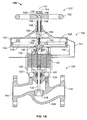
- FIG. 1A illustrates a cross-sectional view of an example control valve implemented with a manual override apparatus described herein and shown in a closed position.
- FIG. 1B illustrates a cross-sectional view of the example control valve of FIG. 1A shown in an open position.
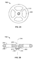
- FIG. 2A is a plan view of the example manual operator of FIGS. 1A and 1B and FIG. 2B is a cross-sectional view of the example manual operator of FIGS. 1A , 1B , and 2A .
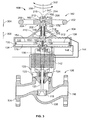
- FIG. 3 illustrates a cross-sectional view of the example control valve of FIGS. 1A and 1B manually moved to the closed position via the example manual override apparatus of FIGS. 1A , 1B , 2A and 2B .
- FIG. 4 illustrates a cross-sectional view of the example control valve of FIGS. 1A and 1B in a failed closed position.
- FIG 5 illustrates a cross-sectional view of the example control valve of FIG. 4 manually moved to the open position via the example manual override apparatus of FIGS. 1A , 1B , 2A and 2B .
- a control fluid e.g.. air
- a valve actuator e.g., pneumatic actuator
- it may be necessary to manually override the position of a flow control member of a valve to a desired position e.g., a closed position of FIG. 3 , an open position or FIG. 5 , etc.
- a desired position e.g., a closed position of FIG. 3 , an open position or FIG. 5 , etc.
- the automatic control system fails to supply control fluid to the actuator, it may be necessary to open the valve to prevent overpressurization of a vessel or it may be necessary to close the valve to prevent a spill (e.g., a chemical spill).
- known manual override mechanisms for control valves permit manual operation of the valve and do not require an outside power source to move the flow control member of the valve to a desired position.
- these known manual override mechanisms typically use a hand wheel, a chain wheel, a lever, a declutchable mechanism, or a combination thereof, to drive a series of gears (e.g., a worm drive gearbox, etc.) providing a reduction that results in a higher output torque compared to an input (manual) torque provided by a person.
- gears e.g., a worm drive gearbox, etc.
- Some known manual override mechanisms use a worm drive gearbox in which a self-locking worm and worm gear drive holds the valve in a desired position.
- this configuration usually requires aligning a hole in a manual override stem with a hole in an actuator stem and sliding a pin therethrough to engage the manual override mechanism. During emergency situations, this process can be time consuming and unacceptable.
- Other known applications utilize a declutchable worm drive gear box that involves manually engaging a lever to enable manual operation of a valve via a hand wheel.
- worm drive gearboxes are relatively expensive, difficult to operate, enlarge the dimensional envelope of the valve and actuator assembly, and involve complex assemblies with the actuator.
- Another known example manual override mechanism provides a hand wheel and screw combination that is mounted directly to an actuator to manually operate a valve.
- this known configuration limits operation of some valves in one direction and, thus, once these valves are manually operated, the override mechanism cannot be used to operate the valve in the other or opposite direction. Therefore, these known manual override mechanisms cannot be used with double acting actuators.
- the example manual override apparatus described herein may be used to selectively engage or operate an actuator.
- the example manual override apparatus enables manual control of the actuator to position a flow control member of a valve at any position between a fully open position in which the flow of fluid through the valve is permitted and a fully closed position in which the flow of fluid through the valve is restricted or prevented.
- the example, manual override apparatus described herein is particularly advantageous for use with double acting actuators (i.e., actuators in which pressurized fluid is used to open and close the valve) because the example manual override apparatus provides dual direction operation or rectilinear movement of the actuator (i.e., moving the actuator in a first direction and a second direction opposite the first direction).
- the example manual override apparatus described herein may be used with valves having a linear actuator such as, for example, control valves, throttling valves, on/off valves, etc. Additionally, the example manual override apparatus may be used with fluid-to-open actuated valves (i.e., valves in which a spring biases the valve in the closed position) or fail-to-close actuated valves (i.e., valves in which a spring biases the valve in the opened position).
- fluid-to-open actuated valves i.e., valves in which a spring biases the valve in the closed position
- fail-to-close actuated valves i.e., valves in which a spring biases the valve in the opened position
- the example manual override apparatus described herein is less expensive and reduces the dimensional envelope of the valve and actuator assembly because the example manual override apparatus does not have a declucthable mechanism or an expensive gear box configuration, which typically involves manually engaging a lever to enable operation of the valve via the manual override apparatus.
- F.IG. 1A illustrates a cross-sectional view of an example control valve 100 implemented with an example manual override apparatus 102 described herein and showing the example control valve 100 in a closed position.
- FIG. 1B illustrates a cross-sectional view of the example control valve 100 of FIG. 1A shown in an open position.
- the example control valve 100 includes an actuator 104 to move or operate a valve 106 between an open position to allow fluid flow through the valve 106 and a closed position to prevent or restrict the fluid flow through the valve 106.
- the valve 106 has a valve body 108 that is the main pressure boundary of the valve 106 and includes a valve seat 110 ( FIG. 1B ) disposed therein to define an orifice 112 ( FIG. 1B ) that provides a fluid flow passageway between an inlet 114 and an outlet 116.
- a flow control member 118 is operatively coupled to the actuator 104 via a valve stem 120.
- the actuator 104 moves the flow control member 118 in a first direction (e.g., toward the valve seat 110) to restrict or prevent the flow of fluid between the inlet 114 and the outlet 116 as shown in FIG. 1A and a second direction (e.g., away from the valve seat 110) to allow the flow of fluid between the inlet 114 and the outlet 116 as shown in FIG. 1B .
- the position of the flow control member 118 relative to the valve seat 110 varies or controls the fluid flow rate through the control valve 100.
- a bonnet 122 houses the valve stem 120 and includes a packing system 124 to prevent leakage of process fluid along the valve stem 120 and outside the valve body 108 into the environment surrounding the valve 100. Also, the bonnet 122 couples the valve body 108 to a yoke 126, which couples the valve 106 to the actuator 104. In some examples, a cage (not shown) may be disposed in the valve body 108 to slidably receive the flow control member 118 to provide certain flow characteristics of the fluid (e.g., reduced noise, reduced cavitation generated by the flow of fluid through the valve 106, etc.).
- the actuator 104 shown in FIGS. 1A and 1B is commonly referred to as a double acting actuator (i.e., in which pressurized fluid is used to open and close the valve 108).
- An actuation member 128 e.g., a piston, a diaphragm, etc.
- An actuator stem 136 is coupled to the actuation member 128 at a first end 138 and is coupled to the valve stem 120 at a second end 140.
- a travel indicator may be coupled to the second end 140 of the actuator stem 136 or the valve stem 120 to follow or indicate the position of the actuator 104 and, thus, the position of the flow control member 118 relative to the valve seat 110 (e.g., an open position, a closed position, an intermediate position, etc.).
- the travel indicator may be configured to provide a signal (e.g., a mechanical signal, an electrical signal, etc.) to a control unit or positioner 142.
- the control unit or positioner 142 supplies control fluid (e.g., pressurized air, hydraulic oil, etc.) to the first chamber 132 via a first port or passageway 144 (e.g., a hose) and the second chamber 134 via a second port or passageway 146 (e.g., a hose) based on the signal (e.g., a mechanical signal, an electronic signal, etc.) provided by the travel indicator.
- control fluid e.g., pressurized air, hydraulic oil, etc.
- the pressure differential across the actuation member 128 moves the actuation member 128 in a first direction (e.g., a rectilinear path along an axis 147) and a second direction (e.g., a rectilinear path along the axis 147) opposite the first direction.
- a first direction e.g., a rectilinear path along an axis 147
- a second direction e.g., a rectilinear path along the axis 147
- the example manual override apparatus 102 enables manual movement or operation of the flow control member 118 between the closed position shown in FIG. 1A and the open position shown in FIG. 1B .
- the manual override apparatus 102 includes a first drive member 148 that slidably receives a second drive member or stem, 150.
- the first drive member 140 is a stem and the second drive member 150 is a leadscrew.
- the first drive member 148 or the second drive member 150 may be a stem, a shaft, or any other suitable drive members.
- a manual operator 152 removably couples to either of the stem 148 and/or the leadscrew 150 to manually drive the stem 148 or the leadscrew 150.
- the stem 148 and the leadscrew 150 are coaxially aligned with the actuator stem 136 about the axis 147.
- the stem 148 is threadably coupled to the housing 130 of the actuator 104 and is driven in a first direction along a rectilinear path along the axis 147 to selectively engage a first side 154 of the actuation member 128.
- the stem 148 includes a body having a bore 156 and having at least an externally threaded portion 158 between a first end 160 and a second end 162.
- the threads of the threaded portion 158 are right-handed threads.
- the threads of the threaded portion 158 may be left-handed threads and/or any other suitable threads.
- the first end 160 of the stem 148 has a hex-shaped cross-sectional shape.
- the first end 160 may have a square cross-sectional shape or any other suitable cross-sectional shape.
- the leadscrew 150 is slidably and rotatably coupled to the stem 148.
- the leadscrew 150 includes a first end 164 having a head portion 166 to engage the first end 160 of the stem 148 and a body 168 disposed within (e.g., in a bore of) the hollow body 156 of the stem 148.
- At least a portion of the body 168 of the leadscrew 150 at a second end 170 has threads 172 to threadably engage the first end 138 of the actuator stem 136.
- the first end 138 of the actuator stem 136 has a threaded aperture 174 to receive the second end 170 of the leadscrew 150.
- the leadscrew 150 has right-handed threads substantially similar to (e.g., having the same pitch as) the right-handed threads of the threaded aperture 174 of the actuator stem 136.
- the threads 172 of the leadscrew 150 and/or the threads of the threaded aperture 174 may be left-handed threads and/or any other suitable threads.
- the head portion 166 of the leadscrew 150 has an aperture 176 substantially perpendicular to the axis 147.
- FIG. 2A is a top view of the manual operator 152 of FIGS. 1 A and 1B and FIG. 2B is a cross-sectional view of the manual operator 152 of FIGS. 1A , 1B , and 2A .
- the manual operator 152 is depicted as a handwheel.
- the manual operator 152 includes a first coupling 202 on a first side 204 of the manual operator 152 and a second coupling 206 on a second side 208 opposite the first side 204.
- the first coupling 202 removably couples the manual operator 152 to the first end 160 of the stem 148 to rotate the stem 148 about the axis 147.
- the first coupling 202 includes an aperture 210 having a hex cross-sectional shape that is to matably engage the hex cross-sectional shape of the first end 160 of the stem 148.
- the first coupling 202 may have any suitable cross-sectional shape substantially similar or complementary to the cross-sectional shape of the first end 160 of the stem 148.
- the first coupling 202 may couple to the stem 148 via any other suitable fastening mechanism(s) such as, for example, a pin, a fastener, a clip, etc.
- the second coupling 206 removably couples the manual operator 152 to the first end 164 of the leadscrew 150 to rotate the leadscrew 150 about the axis 147.
- the second coupling 206 includes a cylindrically shaped hub 212 having a bore 214 to receive the first end 164 (i.e., the head 166) of the leadscrew 150.
- the hub 212 includes an aperture 216 substantially perpendicular to an axis 218 of the hub 212.
- the aperture 176 in the head 166 of the leadscrew 150 aligns with the aperture 216 of the hub 212 to receive a pin or clip member 402 ( FIGS.
- the pin 402 is required only to couple the manual operator 152 to the leadscrew 150 via the second coupling 206. Thus, the pin 402 is removed from the apertures 176 and 216 in normal operations and/or when the manual operator 152 is coupled to the stem 148 via the first coupling 202.
- the pin member 402 may be, for example, a pin having a spring detent and may include a ring to facilitate its removal from or insertion into the apertures 176 and 216. Additionally, although not shown, the pin member 402 may be tethered to the manual operator 152.
- the manual operator 152 is coupled to the stem 148 via the first coupling 204 (and the pin 402 is removed from the apertures 176 and 216).
- the positioner 142 supplies control fluid to the first chamber 132 to exert a force on the first side 154 of the actuation member 128 that is greater than the force exerted on a second side 178 of the actuation member 128 by the control fluid in the second chamber 134 (e.g., the fluid in the second chamber 134 is released or removed via the second port 146) to move the actuation member 128 in a first direction (e.g., a downward direction in the orientation of FIG. 1A ).
- a first direction e.g., a downward direction in the orientation of FIG. 1A
- Movement of the actuation member 128 in the first direction causes the actuator stem 136, the valve stem 120 and, thus, the flow control member 118 to move in a rectilinear path along the axis 147 toward the valve seat 110. As shown in FIG. 1A , in the closed position, the flow control member 118 sealingly engages the valve seat 110 to prevent the flow of fluid through the valve 106.
- the positioner 142 supplies control fluid to the second chamber 134 to exert a force on the second side 178 of the actuation member 128 that is greater than the force exerted on the first side 154 of the actuation member 128 by the fluid in the first chamber 132 (e.g., the fluid in the first chamber 132 is released or removed via the first port 144).
- Movement of the actuation member 128 in the second direction causes the actuator stem 136, the leadscrew 150, and the valve stem 120 to move in the second direction and, thus, the flow control member 118 to move in a rectilinear path along the axis 147 away from the valve seat 110 to allow the flow of fluid through the valve 106 as shown in FIG. 1B .
- the positioner 142 supplies control fluid to the first and second chambers 132 and 134 to vary the position of the flow control member 118 between the closed position ( FIG. 1A ) at which the flow control member 118 sealingly engages the valve seat 110 and the fully open or maximum flow rate position ( FIG. 1B ) at which the flow control member 118 is spaced away from the valve seat 110.
- the manual override apparatus 102 does not affect or impair the automatic operation of the control valve 100. More specifically, the manual override apparatus 102 does not interfere with the actuator 104 when the control valve 100 is operating normally between the first position ( FIG. 1A ) and the second position ( FIG. 1B ) while the manual operator 152 coupled to the first end 160 of the stem 148 via the first coupling 202. Also, although the leadscrew 150 is threadably coupled to and, thus, moves in a rectilinear path along the axis 147 with the actuator stem 136, the leadscrew 150 (or the manual override apparatus 102) does not interfere with the operation of the control valve 100. As clearly shown in FIG.
- the leadscrew 150 is not coupled to the manual operator 152 (e.g., a pin is removed from the apertures 176 and 216) when the control valve 100 is in operation (and when the manual operator 152 is coupled to the stem 148), the leadscrew 150 slides within the hollow body 156 (e.g., the bore) of the stem 148.
- the first end 164 e.g., the head 166) slides through the apertures 210 and 214 of the manual operator 152.
- the manual operator 152 may be coupled to the control valve 100 such that the the first coupling 202 of the manual operator 152 engages the first end 160 of the stem 148.
- the manual operator 152 may be removed from the control valve 100 during normal operation.
- FIG. 3 illustrates the example control valve 100 having the flow control member 118 manually moved to the closed position via the example manual override apparatus 102.
- the first coupling 202 of the manual operator 152 is coupled to the first end 160 of the stem 148.
- the pin member 402 is not required when the manual operator 152 is coupled to the stem 148 via the first coupling 204.
- An operator manually rotates the manual operator 152 in a first rotational direction 302 (e.g., a clockwise direction) about the axis 147.
- Rotation of the manual operator 152 in the first rotational direction 302 causes the stem 148 to rotate in the first rotational direction 302.
- rotation of the stem 148 in the first rotational direction 302 causes the stem 148 to move in a first linear direction 304 (e.g., a downward direction toward the actuation member 128 in the orientation of FIG. 3 ) along the axis 147.
- the second end 162 of the stem 148 engages the first side 154 of the actuation member 128 to move or displace the actuation member 128 and thus, the flow control member 118 along a rectilinear path in the first linear direction 304 so that the flow control member 118 sealingly engages the valve seat 110 to prevent the flow of fluid through the valve 106 as shown in FIG. 3 .
- the operator rotates the manual operator 152 in a second rotational direction 306 (e.g., a counterclockwise direction) opposite the first rotational direction 302 (e.g., the clockwise direction).
- Rotation of the stem 148 in the second rotational direction 306 causes the second end 162 to retract or move in a second linear direction 308 (e.g., in a direction away from the first side 154 of the actuation member 128).
- the stem 148 translates rotational motion to linear motion to selectively engage the actuation member 128 and drive the actuation member 128 in the first linear direction 304.
- a retainer 310 (e.g., a C-ring) is disposed along a portion of the stem 148 that engages a first surface 312 of the housing 130 to limit movement of the stem 148 in the first linear direction 304 when the stem 148 is rotated in the first rotational direction 302.
- the retainer 310 engages a second surface 314 of the housing 130 to prevent or limit movement of the stem 148 in the second linear direction 308 when the stem 148 is rotated in the second rotational direction 306.
- FIG. 4 illustrates the control valve 100 in a failed closed position
- FIG. 5 illustrates the control valve 100 manually moved to the open position via the manual override apparatus 102.
- an operator turns over (e.g., flips) the manual operator 152 so that the first side 204 of the manual operator 152 is opposite (e.g., facing away) from the actuator 102.
- the second coupling 206 is coupled to or engages the head 166 of the leadscrew 150 so that the aperture 176 of the head 166 and the aperture 216 of the hub 212 are aligned.
- the operator inserts the pin 402 through the apertures 176 and 216 to couple the manual operator 152 to the leadscrew 150.
- the operator rotates the leadscrew 150 in the first rotational direction 302.
- Rotation of the leadscrew 150 in the first rotational direction 302 causes the leadscrew 150 to rotate relative to the stem 148.
- the manual operator 152 is coupled to the leadscrew 150 via the second coupling 204.
- rotation of the leadscrew 150 does not cause the stem 148 to rotate in the first rotational direction 302 or the second rotational direction 306.
- the leadscrew 150 rotates relative (e.g., within) the stem 148 when the manual operator 152 is coupled to the leadscrew 150 via the second coupling 204.
- the leadscrew 150 As the leadscrew 150 is rotated relative to the stem 148, the head 166 of the leadscrew 150 engages the first end 160 of the stem 148. Thus, the leadscrew 150 does not move in the first linear direction 304 along the axis 147 (e.g., toward the actuation member 128) because the stem 148 is stationary (i.e., docs not move in either the first or second rotational directions 302 or 306 or the first and second linear directions 304 and 308) while the leadscrew 150 rotates in the first rotational direction 302.
- the threads 172 of the leadscrew 150 engage the threads of the threaded aperture 174 of the actuator stem 136.
- the threads e.g., right-handed threads
- the actuator stem 136 moves (e.g., lift) in the second linear direction 308 and, thus, causes the actuation member 128 to move in a rectilinear path along the axis 147 in the second linear direction 308 (e.g., toward the first chamber 132).
- rotation of the leadscrew 150 relative to the stem 148 in the first rotational direction 302 causes the flow control member 118 to move to the open position of FIG. 5 . Therefore, the leadscrew 150 translates rotational motion of the leadscrew 150 to linear motion of the actuation member 128 of the actuator 104 along a rectilinear path in the second linear direction 308 (e.g., an upward direction).
- frictional forces between the stem 148 and the leadscrew 150 do not cause the stem 148 to rotate with the leadscrew 150 when the leadscrew 150 is rotated via the second coupling 206 of the manual operator 152 because the head portion 166 engages the first end 160 of the stem 148 and the pin member 402 couples the manual operator 152 to the leadscrew 150.
- the manual operator 152 does not engage the stem 148 when the manual operator 152 is coupled to the leadscrew 150 via the second coupling 206.
- frictional forces may cause the leadscrew 150 to rotate together with the stem 148 when the stem 148 is rotated in the first or second rotational directions 302 and 306 about the axis 147 via the first coupling 202.
- the leadscrew 150 does not cause the actuation member 128 to move in the first or second linear directions 304 and 308. respectively, because the external threads (e.g., right-handed threads) of the stem 148 have a pitch substantially similar or identical to the pitch of the threads 172 (e.g., right-handed threads) of the second end 170 of the leadscrew 150.
- rotation of the first and second drive members 148 and 150 in the first rotational direction 302 causes the leadscrew 150 to thread further into the actuator stem 136 without causing the actuation member 128 to displace because the stem 148 also moves in the first linear direction 304 along with the leadscrew 150 (i.e., the leadscrew 150 does not rotate relative to the stem 148).
- the example override apparatus 102 is not limited to the example actuator 104 (e.g., a double acting actuator) described herein.
- the example override apparatus 102 may be used with any actuators such as, for example, spring return piston actuators, and/or any other suitable actuator commonly used to operate control valves. Additionally, the example described in connection with the manual override apparatus is not limited to the example valve 106 of FIGS.
- valves such as, for example, a sliding stem valve (e.g., a gate valve, a globe valve, etc.), a rotary valve (e.g., a ball valve, a disk valve, a butterfly valve, etc.) and/or any other suitable valve that are operated via linear actuators such as, for example, the actuator 104 of FIG. 1B and/or any other suitable actuator.
- a sliding stem valve e.g., a gate valve, a globe valve, etc.
- a rotary valve e.g., a ball valve, a disk valve, a butterfly valve, etc.
- linear actuators such as, for example, the actuator 104 of FIG. 1B and/or any other suitable actuator.
Landscapes
- Engineering & Computer Science (AREA)
- General Engineering & Computer Science (AREA)
- Mechanical Engineering (AREA)
- Mechanically-Actuated Valves (AREA)
- Transmission Devices (AREA)
- Fluid-Driven Valves (AREA)
- Lock And Its Accessories (AREA)
- Air Bags (AREA)
Claims (10)
- Appareil de commande manuelle (100) destiné à être utilisé avec une soupape, comprenant :un opérateur manuel (152) ayant un premier accouplement (202) sur un premier coté (204) et un second accouplement (206) sur un second côté (208) opposé au premier coté (204) par rapport à un axe longitudinal (218) de l'opérateur manuel (152) ;un premier élément d'entraînement (148) ayant des filets extérieurs (158) qui peuvent être couplés à un boîtier (130) d'un actionneur (104), dans lequel le premier élément d'entraînement (148) comprend une première extrémité (160) pour recevoir de manière amovible le premier accouplement (202) de l'opérateur manuel (152), une seconde extrémité (162) qui peut être mise en prise de manière sélective avec un élément d'actionnement (128) de l'actionneur (104), et un alésage (156) traversant le long d'un axe longitudinal (147) du premier élément d'entraînement (148) ; etun second élément d'entraînement (150) disposé dans l'alésage (156) pour être relié de manière rotative au premier élément d'entraînement (148), le second élément d'entraînement (150) ayant une première extrémité (164) pour recevoir de manière amovible le second accouplement (206) de l'opérateur manuel (152), et une seconde extrémité (170) qui peut être reliée de manière vissée à une tige d'actionneur (136) de l'élément d'actionnement (128),dans lequel une rotation du premier élément d'entraînement (148) dans un premier sens de rotation par l'intermédiaire de l'opérateur manuel (152) déplace l'élément d'actionnement (128) de l'actionneur (104) dans une première direction linéaire et une rotation du second élément d'entraînement (150) par rapport au premier élément d'entraînement (148) dans le premier sens de rotation par l'intermédiaire de l'opérateur manuel (152) amène l'élément d'actionnement (128) à se déplacer dans une seconde direction linéaire opposée à la première direction linéaire.
- Appareil selon la revendication 1, dans lequel le second élément d'entraînement (150) est relié de manière coulissante au premier élément d'entraînement (148).
- Appareil selon la revendication 1, dans lequel l'opérateur manuel (152) comprend un volant.
- Appareil selon la revendication 1, dans lequel le premier accouplement (202) de l'opérateur manuel (152) comprend une ouverture de forme hexagonale pour recevoir la première extrémité du premier élément d'entraînement et le second accouplement de l'opérateur manuel (152) comprend un moyeu ayant un alésage pour recevoir la seconde extrémité du second élément d'entraînement et une ouverture sensiblement perpendiculaire à l'alésage.
- Appareil selon la revendication 4, dans lequel la première extrémité du premier élément d'entraînement (148) est constituée d'une forme hexagonale.
- Appareil selon la revendication 4, dans lequel la seconde extrémité du second élément d'entraînement (150) comprend un corps de forme cylindrique ayant une ouverture qui est destinée à être alignée avec l'ouverture du second accouplement pour recevoir un axe pour relier le second élément d'entraînement (150) au second accouplement de l'opérateur manuel (152) lorsque le second élément d'entraînement doit être mis en rotation dans le premier sens.
- Appareil selon la revendication 6, dans lequel le corps de forme cylindrique est en prise avec la première extrémité du premier élément d'entraînement (148) pour empêcher un mouvement rectiligne du second élément d'entraînement (150) le long d'un axe longitudinal de la tige d'actionneur (136) lorsque le second élément d'entraînement est mis en rotation par rapport au premier élément d'entraînement par l'intermédiaire de l'opérateur manuel (152).
- Appareil selon la revendication 1, dans lequel le premier élément d'entraînement (148) et le second élément d'entraînement (150) sont alignés sensiblement coaxialement avec la tige d'actionneur (136).
- Appareil selon la revendication 1, dans lequel les filets du premier élément d'entraînement (148) et les filets du second élément d'entraînement (150) ont le même pas.
- Soupape de commande (100), comprenant :l'appareil de commande manuelle (102) de la revendication 1 ; etun actionneur (104) ayant un élément d'actionnement (128) disposé dans un boîtier (130) et une tige d'actionneur (136) reliée à l'élément d'actionnement (128) à une première extrémité (138) et reliée à une tige de soupape (120) d'une soupape à une seconde extrémité (140),dans lequel l'appareil de commande manuelle (100) est relié au boîtier (130) de l'actionneur (104).
Applications Claiming Priority (2)
| Application Number | Priority Date | Filing Date | Title |
|---|---|---|---|
| US12/365,663 US8070127B2 (en) | 2009-02-04 | 2009-02-04 | Manual override apparatus for linear actuators |
| PCT/US2010/021392 WO2010090816A1 (fr) | 2009-02-04 | 2010-01-19 | Appareil de priorité manuelle pour actionneurs linéaires |
Publications (2)
| Publication Number | Publication Date |
|---|---|
| EP2394082A1 EP2394082A1 (fr) | 2011-12-14 |
| EP2394082B1 true EP2394082B1 (fr) | 2013-01-16 |
Family
ID=42077528
Family Applications (1)
| Application Number | Title | Priority Date | Filing Date |
|---|---|---|---|
| EP10701284A Active EP2394082B1 (fr) | 2009-02-04 | 2010-01-19 | Appareil de priorité manuelle pour actionneurs linéaires |
Country Status (11)
| Country | Link |
|---|---|
| US (1) | US8070127B2 (fr) |
| EP (1) | EP2394082B1 (fr) |
| JP (1) | JP5457467B2 (fr) |
| CN (1) | CN102308134B (fr) |
| AU (1) | AU2010210944B2 (fr) |
| BR (1) | BRPI1007307A2 (fr) |
| CA (1) | CA2750277C (fr) |
| MX (1) | MX2011008193A (fr) |
| NO (1) | NO340106B1 (fr) |
| RU (1) | RU2523458C2 (fr) |
| WO (1) | WO2010090816A1 (fr) |
Families Citing this family (14)
| Publication number | Priority date | Publication date | Assignee | Title |
|---|---|---|---|---|
| US8215241B2 (en) * | 2010-02-25 | 2012-07-10 | Msb Design | Vertical linear actuator mechanism |
| CN103403419B (zh) * | 2010-12-28 | 2016-03-30 | 艾默生过程管理(天津)阀门有限公司 | 用于滑动杆控制阀组件的液压致动设备 |
| CN102182422A (zh) * | 2011-05-24 | 2011-09-14 | 江苏金石富源机械有限公司 | 调压单流阀 |
| US9194108B2 (en) | 2012-02-07 | 2015-11-24 | Mueller International, Llc | Flushing hydrant with fail-safe |
| CA2863349C (fr) * | 2012-02-07 | 2020-01-21 | Mueller International, Llc | Rincage de bouche d'incendie |
| CN102900859B (zh) * | 2012-10-29 | 2014-02-12 | 宝鸡石油机械有限责任公司 | 水下液压驱动型平板闸阀 |
| CN102927355A (zh) * | 2012-11-15 | 2013-02-13 | 无锡智能自控工程股份有限公司 | 一种内置式角阀故障锁定机构 |
| US10371281B2 (en) * | 2013-09-06 | 2019-08-06 | Ge Oil & Gas Pressure Control Lp | Hybrid manual and hydraulic override |
| US9500294B2 (en) | 2013-09-06 | 2016-11-22 | Ge Oil & Gas Pressure Control Lp | Hybrid manual and hydraulic actuator override |
| KR101590617B1 (ko) * | 2014-04-04 | 2016-02-01 | 주식회사 유연 | 선박의 화재진압을 위한 메인 밸브 |
| US10096885B2 (en) * | 2014-09-16 | 2018-10-09 | Commscope Technologies Llc | Transversely clampable linear adjustment mechanism |
| US10578220B2 (en) | 2017-02-27 | 2020-03-03 | Bimba Manufacturing Company | Proportionally controlled pinch valves, systems and methods |
| US10564653B2 (en) | 2018-04-13 | 2020-02-18 | Mueller International, Llc | Flushing verification and management system |
| RU205093U1 (ru) * | 2021-03-10 | 2021-06-28 | Общество с ограниченной ответственностью НПО "Сибирский Машиностроитель" | Малогабаритный электропривод для трубопроводной арматуры |
Family Cites Families (33)
| Publication number | Priority date | Publication date | Assignee | Title |
|---|---|---|---|---|
| US935856A (en) | 1908-04-29 | 1909-10-05 | Jeremiah O'meara | Valve. |
| US2403427A (en) | 1944-01-27 | 1946-07-02 | Skinner Engine Co | Valve mechanism |
| US2370604A (en) * | 1944-03-02 | 1945-02-27 | Crane Co | Valve actuating means |
| US2630829A (en) | 1947-07-30 | 1953-03-10 | Shafer Valve Co | Valve operating mechanism |
| US2890014A (en) * | 1955-12-19 | 1959-06-09 | Worthington Corp | Pressure responsive valve |
| DE1113344B (de) | 1957-12-18 | 1961-08-31 | Acf Ind Inc | Kombinierter Druckmittel- und Handantrieb fuer Ventile u. dgl. taetige Verschluesse |
| FR1300618A (fr) | 1961-09-18 | 1962-08-03 | Jansen Gmbh Th | Vanne d'arrêt à surfaces de joint obliques |
| US3290003A (en) | 1962-10-29 | 1966-12-06 | G & H Products Corp | Valve construction facilitating removal of parts |
| US3734455A (en) | 1971-09-21 | 1973-05-22 | Acf Ind Inc | Safety device for a fluid cylinder valve actuator |
| USRE29322E (en) * | 1971-09-29 | 1977-07-26 | Teledyne Merla, div. of Teledyne, Inc. | Valve and actuator assembly |
| US3842854A (en) | 1973-04-16 | 1974-10-22 | Acf Ind Inc | Heat responsive safety device for manual gate valve operators |
| SU457840A1 (ru) * | 1973-05-10 | 1975-01-25 | Научно-Производственное Объединение "Киеварматура" | Механизм переключени приводов |
| US3842690A (en) * | 1973-05-10 | 1974-10-22 | Res Eng Co | Automatically disengageable manual control |
| US3946985A (en) * | 1974-02-28 | 1976-03-30 | Tokico Ltd. | Valve device for gases |
| US4619434A (en) * | 1981-02-17 | 1986-10-28 | Axelson, Inc. | Heat sensitive motor valve jack |
| US4414995A (en) | 1982-04-08 | 1983-11-15 | Spencer Larry K | Three-way hydraulic controller |
| SU1142685A1 (ru) * | 1982-12-27 | 1985-02-28 | Предприятие П/Я А-7899 | Электропривод с ручным дублером |
| US4605039A (en) * | 1984-10-04 | 1986-08-12 | Stewart-Warner Corporation | Runaway protective fuse valve |
| US4617992A (en) * | 1985-05-03 | 1986-10-21 | Abel Thomas E | System and choke valve actuator mechanism for operating a plunger lift well |
| CN2033873U (zh) * | 1988-04-09 | 1989-03-08 | 朱兆坤 | 流体控制装置 |
| ES2030811T3 (es) * | 1988-08-18 | 1992-11-16 | Festo Kg | Dispositivo lineal de impulsion. |
| US4921207A (en) * | 1989-08-22 | 1990-05-01 | Cameron Iron Works Usa, Inc. | Actuated gate valve with manual override |
| GB2243669B (en) * | 1990-05-04 | 1994-06-01 | Ava Int Corp | Fail safe valve actuator |
| FR2712955B1 (fr) | 1993-11-25 | 1995-12-22 | Pyromeca | Dispositif de manÓoeuvre d'une vanne à obturateur se déplaçant par translation. |
| AU2092095A (en) * | 1994-03-04 | 1995-09-18 | Safoco, Inc. | Valve actuator apparatus and method |
| US5477752A (en) * | 1994-03-07 | 1995-12-26 | Dyna-Torque Company, Inc. | Valve actuator declutch mechanism |
| RU2103582C1 (ru) * | 1996-05-05 | 1998-01-27 | Открытое акционерное общество "Пензтяжпромарматура" | Электромоторный привод с ручным дублером |
| FR2817940B1 (fr) | 2000-12-08 | 2004-04-30 | Atofina | Robinet a commande par servomoteur pour recipient de fluides toxiques |
| US6575426B2 (en) * | 2001-08-09 | 2003-06-10 | Worldwide Oilfield Machine, Inc. | Valve system and method |
| US6722528B2 (en) * | 2002-03-14 | 2004-04-20 | Fisher Controls International, Inc. | Rotary pneumatic actuator |
| WO2005088180A1 (fr) * | 2004-03-10 | 2005-09-22 | Swagelok Company | Actionneur de dispositif fluidique a neutralisation manuelle |
| EP1793114B1 (fr) | 2005-12-02 | 2013-05-15 | Behr Thermot-tronik GmbH | Appareil, en particulier vanne de recyclage des gaz d'échappement, pour commander un courant de fluide |
| JP4517371B2 (ja) * | 2006-12-25 | 2010-08-04 | Smc株式会社 | 流量調整弁 |
-
2009
- 2009-02-04 US US12/365,663 patent/US8070127B2/en active Active
-
2010
- 2010-01-19 MX MX2011008193A patent/MX2011008193A/es active IP Right Grant
- 2010-01-19 CA CA2750277A patent/CA2750277C/fr active Active
- 2010-01-19 CN CN2010800065720A patent/CN102308134B/zh active Active
- 2010-01-19 AU AU2010210944A patent/AU2010210944B2/en not_active Ceased
- 2010-01-19 WO PCT/US2010/021392 patent/WO2010090816A1/fr active Application Filing
- 2010-01-19 JP JP2011548057A patent/JP5457467B2/ja not_active Expired - Fee Related
- 2010-01-19 RU RU2011135328/06A patent/RU2523458C2/ru active
- 2010-01-19 EP EP10701284A patent/EP2394082B1/fr active Active
- 2010-01-19 BR BRPI1007307A patent/BRPI1007307A2/pt not_active Application Discontinuation
-
2011
- 2011-07-21 NO NO20111051A patent/NO340106B1/no not_active IP Right Cessation
Also Published As
| Publication number | Publication date |
|---|---|
| AU2010210944A1 (en) | 2011-08-11 |
| MX2011008193A (es) | 2011-08-17 |
| CN102308134B (zh) | 2013-09-04 |
| US8070127B2 (en) | 2011-12-06 |
| RU2523458C2 (ru) | 2014-07-20 |
| CA2750277C (fr) | 2015-10-27 |
| RU2011135328A (ru) | 2013-03-10 |
| JP2012516978A (ja) | 2012-07-26 |
| WO2010090816A1 (fr) | 2010-08-12 |
| JP5457467B2 (ja) | 2014-04-02 |
| CA2750277A1 (fr) | 2010-08-12 |
| US20100193715A1 (en) | 2010-08-05 |
| CN102308134A (zh) | 2012-01-04 |
| AU2010210944B2 (en) | 2016-02-25 |
| NO340106B1 (no) | 2017-03-13 |
| BRPI1007307A2 (pt) | 2016-02-10 |
| NO20111051A1 (no) | 2011-07-21 |
| EP2394082A1 (fr) | 2011-12-14 |
Similar Documents
| Publication | Publication Date | Title |
|---|---|---|
| EP2394082B1 (fr) | Appareil de priorité manuelle pour actionneurs linéaires | |
| US8408518B2 (en) | Electric actuators having internal load apparatus | |
| EP2499410B1 (fr) | Couplage pour utiliser avec des actionneurs électriques | |
| EP2191181B1 (fr) | Appareil et procédés pour le fonctionnement en mode prioritaire manuel d'un actionneur linéaire | |
| CN103238016B (zh) | 步进电动机操作平衡的流量控制阀 | |
| US20110193001A1 (en) | Conical Seat Shut Off Valve | |
| US20160091110A1 (en) | Axial fluid valves with annular flow control members | |
| KR20150065899A (ko) | 이중 구동부를 갖춘 액추에이터 | |
| US6585228B1 (en) | Electric valve actuator with eddy current clutch | |
| EP3749884B1 (fr) | Vanne à flux axial à fermeture rapide | |
| US20070194263A1 (en) | Valve arrangement | |
| JPH09203478A (ja) | バルブアクチュエイター | |
| JP5988635B2 (ja) | 弁 |
Legal Events
| Date | Code | Title | Description |
|---|---|---|---|
| PUAI | Public reference made under article 153(3) epc to a published international application that has entered the european phase |
Free format text: ORIGINAL CODE: 0009012 |
|
| 17P | Request for examination filed |
Effective date: 20110825 |
|
| AK | Designated contracting states |
Kind code of ref document: A1 Designated state(s): AT BE BG CH CY CZ DE DK EE ES FI FR GB GR HR HU IE IS IT LI LT LU LV MC MK MT NL NO PL PT RO SE SI SK SM TR |
|
| DAX | Request for extension of the european patent (deleted) | ||
| GRAP | Despatch of communication of intention to grant a patent |
Free format text: ORIGINAL CODE: EPIDOSNIGR1 |
|
| GRAS | Grant fee paid |
Free format text: ORIGINAL CODE: EPIDOSNIGR3 |
|
| GRAA | (expected) grant |
Free format text: ORIGINAL CODE: 0009210 |
|
| AK | Designated contracting states |
Kind code of ref document: B1 Designated state(s): AT BE BG CH CY CZ DE DK EE ES FI FR GB GR HR HU IE IS IT LI LT LU LV MC MK MT NL NO PL PT RO SE SI SK SM TR |
|
| REG | Reference to a national code |
Ref country code: GB Ref legal event code: FG4D |
|
| REG | Reference to a national code |
Ref country code: CH Ref legal event code: EP |
|
| REG | Reference to a national code |
Ref country code: IE Ref legal event code: FG4D |
|
| REG | Reference to a national code |
Ref country code: AT Ref legal event code: REF Ref document number: 594085 Country of ref document: AT Kind code of ref document: T Effective date: 20130215 Ref country code: CH Ref legal event code: EP |
|
| REG | Reference to a national code |
Ref country code: DE Ref legal event code: R096 Ref document number: 602010004664 Country of ref document: DE Effective date: 20130314 |
|
| REG | Reference to a national code |
Ref country code: SE Ref legal event code: TRGR |
|
| REG | Reference to a national code |
Ref country code: AT Ref legal event code: MK05 Ref document number: 594085 Country of ref document: AT Kind code of ref document: T Effective date: 20130116 |
|
| REG | Reference to a national code |
Ref country code: NL Ref legal event code: VDEP Effective date: 20130116 |
|
| REG | Reference to a national code |
Ref country code: LT Ref legal event code: MG4D |
|
| PG25 | Lapsed in a contracting state [announced via postgrant information from national office to epo] |
Ref country code: BG Free format text: LAPSE BECAUSE OF FAILURE TO SUBMIT A TRANSLATION OF THE DESCRIPTION OR TO PAY THE FEE WITHIN THE PRESCRIBED TIME-LIMIT Effective date: 20130416 Ref country code: NO Free format text: LAPSE BECAUSE OF FAILURE TO SUBMIT A TRANSLATION OF THE DESCRIPTION OR TO PAY THE FEE WITHIN THE PRESCRIBED TIME-LIMIT Effective date: 20130416 Ref country code: AT Free format text: LAPSE BECAUSE OF FAILURE TO SUBMIT A TRANSLATION OF THE DESCRIPTION OR TO PAY THE FEE WITHIN THE PRESCRIBED TIME-LIMIT Effective date: 20130116 Ref country code: ES Free format text: LAPSE BECAUSE OF FAILURE TO SUBMIT A TRANSLATION OF THE DESCRIPTION OR TO PAY THE FEE WITHIN THE PRESCRIBED TIME-LIMIT Effective date: 20130427 Ref country code: IS Free format text: LAPSE BECAUSE OF FAILURE TO SUBMIT A TRANSLATION OF THE DESCRIPTION OR TO PAY THE FEE WITHIN THE PRESCRIBED TIME-LIMIT Effective date: 20130516 Ref country code: BE Free format text: LAPSE BECAUSE OF FAILURE TO SUBMIT A TRANSLATION OF THE DESCRIPTION OR TO PAY THE FEE WITHIN THE PRESCRIBED TIME-LIMIT Effective date: 20130116 Ref country code: LT Free format text: LAPSE BECAUSE OF FAILURE TO SUBMIT A TRANSLATION OF THE DESCRIPTION OR TO PAY THE FEE WITHIN THE PRESCRIBED TIME-LIMIT Effective date: 20130116 |
|
| PG25 | Lapsed in a contracting state [announced via postgrant information from national office to epo] |
Ref country code: SI Free format text: LAPSE BECAUSE OF FAILURE TO SUBMIT A TRANSLATION OF THE DESCRIPTION OR TO PAY THE FEE WITHIN THE PRESCRIBED TIME-LIMIT Effective date: 20130116 Ref country code: PT Free format text: LAPSE BECAUSE OF FAILURE TO SUBMIT A TRANSLATION OF THE DESCRIPTION OR TO PAY THE FEE WITHIN THE PRESCRIBED TIME-LIMIT Effective date: 20130516 Ref country code: MC Free format text: LAPSE BECAUSE OF NON-PAYMENT OF DUE FEES Effective date: 20130131 Ref country code: PL Free format text: LAPSE BECAUSE OF FAILURE TO SUBMIT A TRANSLATION OF THE DESCRIPTION OR TO PAY THE FEE WITHIN THE PRESCRIBED TIME-LIMIT Effective date: 20130116 Ref country code: GR Free format text: LAPSE BECAUSE OF FAILURE TO SUBMIT A TRANSLATION OF THE DESCRIPTION OR TO PAY THE FEE WITHIN THE PRESCRIBED TIME-LIMIT Effective date: 20130417 Ref country code: NL Free format text: LAPSE BECAUSE OF FAILURE TO SUBMIT A TRANSLATION OF THE DESCRIPTION OR TO PAY THE FEE WITHIN THE PRESCRIBED TIME-LIMIT Effective date: 20130116 Ref country code: LV Free format text: LAPSE BECAUSE OF FAILURE TO SUBMIT A TRANSLATION OF THE DESCRIPTION OR TO PAY THE FEE WITHIN THE PRESCRIBED TIME-LIMIT Effective date: 20130116 |
|
| PG25 | Lapsed in a contracting state [announced via postgrant information from national office to epo] |
Ref country code: HR Free format text: LAPSE BECAUSE OF FAILURE TO SUBMIT A TRANSLATION OF THE DESCRIPTION OR TO PAY THE FEE WITHIN THE PRESCRIBED TIME-LIMIT Effective date: 20130116 |
|
| REG | Reference to a national code |
Ref country code: IE Ref legal event code: MM4A |
|
| PG25 | Lapsed in a contracting state [announced via postgrant information from national office to epo] |
Ref country code: EE Free format text: LAPSE BECAUSE OF FAILURE TO SUBMIT A TRANSLATION OF THE DESCRIPTION OR TO PAY THE FEE WITHIN THE PRESCRIBED TIME-LIMIT Effective date: 20130116 Ref country code: DK Free format text: LAPSE BECAUSE OF FAILURE TO SUBMIT A TRANSLATION OF THE DESCRIPTION OR TO PAY THE FEE WITHIN THE PRESCRIBED TIME-LIMIT Effective date: 20130116 Ref country code: RO Free format text: LAPSE BECAUSE OF FAILURE TO SUBMIT A TRANSLATION OF THE DESCRIPTION OR TO PAY THE FEE WITHIN THE PRESCRIBED TIME-LIMIT Effective date: 20130116 Ref country code: CZ Free format text: LAPSE BECAUSE OF FAILURE TO SUBMIT A TRANSLATION OF THE DESCRIPTION OR TO PAY THE FEE WITHIN THE PRESCRIBED TIME-LIMIT Effective date: 20130116 Ref country code: SK Free format text: LAPSE BECAUSE OF FAILURE TO SUBMIT A TRANSLATION OF THE DESCRIPTION OR TO PAY THE FEE WITHIN THE PRESCRIBED TIME-LIMIT Effective date: 20130116 |
|
| PLBE | No opposition filed within time limit |
Free format text: ORIGINAL CODE: 0009261 |
|
| STAA | Information on the status of an ep patent application or granted ep patent |
Free format text: STATUS: NO OPPOSITION FILED WITHIN TIME LIMIT |
|
| PG25 | Lapsed in a contracting state [announced via postgrant information from national office to epo] |
Ref country code: CY Free format text: LAPSE BECAUSE OF FAILURE TO SUBMIT A TRANSLATION OF THE DESCRIPTION OR TO PAY THE FEE WITHIN THE PRESCRIBED TIME-LIMIT Effective date: 20130116 |
|
| 26N | No opposition filed |
Effective date: 20131017 |
|
| PG25 | Lapsed in a contracting state [announced via postgrant information from national office to epo] |
Ref country code: IT Free format text: LAPSE BECAUSE OF FAILURE TO SUBMIT A TRANSLATION OF THE DESCRIPTION OR TO PAY THE FEE WITHIN THE PRESCRIBED TIME-LIMIT Effective date: 20130116 |
|
| PG25 | Lapsed in a contracting state [announced via postgrant information from national office to epo] |
Ref country code: IE Free format text: LAPSE BECAUSE OF NON-PAYMENT OF DUE FEES Effective date: 20130119 |
|
| REG | Reference to a national code |
Ref country code: DE Ref legal event code: R097 Ref document number: 602010004664 Country of ref document: DE Effective date: 20131017 |
|
| PG25 | Lapsed in a contracting state [announced via postgrant information from national office to epo] |
Ref country code: MT Free format text: LAPSE BECAUSE OF FAILURE TO SUBMIT A TRANSLATION OF THE DESCRIPTION OR TO PAY THE FEE WITHIN THE PRESCRIBED TIME-LIMIT Effective date: 20130116 |
|
| REG | Reference to a national code |
Ref country code: CH Ref legal event code: PL |
|
| PG25 | Lapsed in a contracting state [announced via postgrant information from national office to epo] |
Ref country code: LI Free format text: LAPSE BECAUSE OF NON-PAYMENT OF DUE FEES Effective date: 20140131 Ref country code: CH Free format text: LAPSE BECAUSE OF NON-PAYMENT OF DUE FEES Effective date: 20140131 |
|
| PG25 | Lapsed in a contracting state [announced via postgrant information from national office to epo] |
Ref country code: SM Free format text: LAPSE BECAUSE OF FAILURE TO SUBMIT A TRANSLATION OF THE DESCRIPTION OR TO PAY THE FEE WITHIN THE PRESCRIBED TIME-LIMIT Effective date: 20130116 |
|
| PG25 | Lapsed in a contracting state [announced via postgrant information from national office to epo] |
Ref country code: TR Free format text: LAPSE BECAUSE OF FAILURE TO SUBMIT A TRANSLATION OF THE DESCRIPTION OR TO PAY THE FEE WITHIN THE PRESCRIBED TIME-LIMIT Effective date: 20130116 |
|
| PG25 | Lapsed in a contracting state [announced via postgrant information from national office to epo] |
Ref country code: HU Free format text: LAPSE BECAUSE OF FAILURE TO SUBMIT A TRANSLATION OF THE DESCRIPTION OR TO PAY THE FEE WITHIN THE PRESCRIBED TIME-LIMIT; INVALID AB INITIO Effective date: 20100119 Ref country code: MK Free format text: LAPSE BECAUSE OF FAILURE TO SUBMIT A TRANSLATION OF THE DESCRIPTION OR TO PAY THE FEE WITHIN THE PRESCRIBED TIME-LIMIT Effective date: 20130116 Ref country code: LU Free format text: LAPSE BECAUSE OF NON-PAYMENT OF DUE FEES Effective date: 20130119 |
|
| REG | Reference to a national code |
Ref country code: FR Ref legal event code: PLFP Year of fee payment: 7 |
|
| REG | Reference to a national code |
Ref country code: FR Ref legal event code: PLFP Year of fee payment: 8 |
|
| REG | Reference to a national code |
Ref country code: FR Ref legal event code: PLFP Year of fee payment: 9 |
|
| PGFP | Annual fee paid to national office [announced via postgrant information from national office to epo] |
Ref country code: DE Payment date: 20200129 Year of fee payment: 11 |
|
| REG | Reference to a national code |
Ref country code: DE Ref legal event code: R119 Ref document number: 602010004664 Country of ref document: DE |
|
| PG25 | Lapsed in a contracting state [announced via postgrant information from national office to epo] |
Ref country code: DE Free format text: LAPSE BECAUSE OF NON-PAYMENT OF DUE FEES Effective date: 20210803 |
|
| P01 | Opt-out of the competence of the unified patent court (upc) registered |
Effective date: 20230526 |
|
| PGFP | Annual fee paid to national office [announced via postgrant information from national office to epo] |
Ref country code: GB Payment date: 20231219 Year of fee payment: 15 |
|
| PGFP | Annual fee paid to national office [announced via postgrant information from national office to epo] |
Ref country code: SE Payment date: 20231219 Year of fee payment: 15 Ref country code: FR Payment date: 20231219 Year of fee payment: 15 Ref country code: FI Payment date: 20231219 Year of fee payment: 15 |