EP2394017B1 - Auslöserverbindung - Google Patents
Auslöserverbindung Download PDFInfo
- Publication number
- EP2394017B1 EP2394017B1 EP10703708.7A EP10703708A EP2394017B1 EP 2394017 B1 EP2394017 B1 EP 2394017B1 EP 10703708 A EP10703708 A EP 10703708A EP 2394017 B1 EP2394017 B1 EP 2394017B1
- Authority
- EP
- European Patent Office
- Prior art keywords
- riser
- joint
- fluid
- chamber part
- piston
- Prior art date
- Legal status (The legal status is an assumption and is not a legal conclusion. Google has not performed a legal analysis and makes no representation as to the accuracy of the status listed.)
- Active
Links
Images



Classifications
-
- E—FIXED CONSTRUCTIONS
- E21—EARTH OR ROCK DRILLING; MINING
- E21B—EARTH OR ROCK DRILLING; OBTAINING OIL, GAS, WATER, SOLUBLE OR MELTABLE MATERIALS OR A SLURRY OF MINERALS FROM WELLS
- E21B17/00—Drilling rods or pipes; Flexible drill strings; Kellies; Drill collars; Sucker rods; Cables; Casings; Tubings
- E21B17/02—Couplings; joints
- E21B17/08—Casing joints
- E21B17/085—Riser connections
-
- E—FIXED CONSTRUCTIONS
- E21—EARTH OR ROCK DRILLING; MINING
- E21B—EARTH OR ROCK DRILLING; OBTAINING OIL, GAS, WATER, SOLUBLE OR MELTABLE MATERIALS OR A SLURRY OF MINERALS FROM WELLS
- E21B19/00—Handling rods, casings, tubes or the like outside the borehole, e.g. in the derrick; Apparatus for feeding the rods or cables
- E21B19/002—Handling rods, casings, tubes or the like outside the borehole, e.g. in the derrick; Apparatus for feeding the rods or cables specially adapted for underwater drilling
- E21B19/004—Handling rods, casings, tubes or the like outside the borehole, e.g. in the derrick; Apparatus for feeding the rods or cables specially adapted for underwater drilling supporting a riser from a drilling or production platform
- E21B19/006—Handling rods, casings, tubes or the like outside the borehole, e.g. in the derrick; Apparatus for feeding the rods or cables specially adapted for underwater drilling supporting a riser from a drilling or production platform including heave compensators
Definitions
- the present invention regards a joint for use in riser and a method for extending an operation window for a riser.
- a riser is a pipe extending between a subsea installation and a floating installation for transferring fluids and or signals between equipment at the two installations. There may be produced hydrocarbons, drilling fluids, injection fluids etc. transferred by the riser.
- the floating installation which will move due to changing weather conditions, wind waves, currents etc. is normally given a safe operation window.
- a safe operation window may for instance define an area wherein the installation may move without danger of damaging the equipment, wind conditions where the installation can be kept within this area, etc.
- drift off or drive off situation dependent one the incident occurring are normally release the floating installation from the subsea installation by activating an Emergency Quick Disconnect Package (EQDP) when or before such situations occur.
- EQDP Emergency Quick Disconnect Package
- Document WO 2005/113929 A discloses a heave compensator for a riser, comprising a telescopic connection with a first chamber which is in fluid connection with the interior of the riser and a second chamber which is connected with a source for pressurized fluid.
- the problem is to have enough time for the execution of an emergency disconnect in the event of an emergency situation.
- a drift off/drive off situation of the floating installation or if the heave compensator fails, there is normally very little time available to disconnect the riser from the wellhead.
- activation of the Emergency Quick Disconnect may take more time than is available.
- the object of the present invention is to provide an increased available window for operation of a riser. This is achieved with a joint and a method as defined in the attached claims.
- a joint for use in a riser extending between a floating installation and a subsea installation.
- the subsea installation may be any installation which is kept in a fixed position relative the seabed.
- the floating installation may be a vessel, floating platform, or even an installation floating in the water below the surface of the water but still experiencing movement relative the seabed.
- the joint comprises an inner pipe segment and an outer pipe segments, arranged moveable relative each other in an axial direction of the pipe segments.
- the pipe segments are connectable to respective riser segments.
- the joint will then form part of the riser.
- the pipe segments forms a fluid channel through them, normally arranged in line with the fluid channel of the rest of the riser.
- the pipe segments are configured such that they form a chamber between them.
- a radially extending piston dividing the chamber in a first chamber part and a second chamber part, wherein on of said chamber parts in an initial position of the joint is adapted to contain a mainly incompressible fluid.
- This chamber part is decreasing in volume as the inner pipe segment is moved relatively out of the outer pipe segment.
- the piston is preferably connected to one of said two pipe segments and follows the movement of this pipe segment.
- the joint is configured with a fluid line connection from said one chamber part to the other chamber part.
- This fluid line connection is configured such that the relative movement of the pipe segments is controlled by the allowed flow rate of a fluid flowing through the fluid line connection.
- An outlet from said one chamber part is configured such that the relative movement of the pipe segments is controlled by the allowed flow rate of a fluid flowing out of the chamber part through the outlet.
- This outlet leads to a fluid connection connecting the one chamber part with the other chamber part.
- the fluid line connection may be arranged within the piston element, within the walls forming the chamber part, as equipment attached to one pipe segment or as a combination of these.
- the joint according to the invention When tension is applied to the riser the joint according to the invention will allow some extension in the riser and thereby gain some time for the EQDP to operate before the tension in the riser exceeds threshold values of week links in the riser.
- the joint according to the invention will also act as a brake to slow down and control the rate of extension allowed by the joint, this will also result in that there will be adequate tension in the riser at the time the EQD is activated and ensures that the end of the riser will move off the wellhead.
- There is by controlling the flow out of the chamber part also the possibility to regulate the way the joint extends.
- the controlled outflow also the possibility of operating the flow out of the chamber part to only begin when a threshold value for the tension in the riser is reached.
- a threshold value may also be compensated with regards to pressure within the fluid within the riser, as will be explained below.
- the fluid line connection may comprise a burst disk.
- the burst disk will brake as a result of a pressure in the chamber part exceeding a predetermined pressure level, a threshold value.
- the pressure in the chamber part will be a function on the tension in the riser, as the tension in the riser will try to move the inner pipe segment out of the outer pipe segment and thereby try to reduce the size of the chamber part with the incompressible fluid.
- the pressure of the fluid within the chamber part is a function on the tension in the riser.
- a burst disk may also be configures such that only a small amount of fluid is allowed to flow through the fluid line connection in an initial state after a first threshold value is reached and then is pressure is further increasing and a second threshold value is reached the burst disk may the allow a larger flow through the fluid line connection. In this way the rate of the extension may be regulated at different intervals. There may be additional burst disks arranged in the fluid line connection, braking at different threshold values.
- the fluid line connection may comprises a regulating valve.
- This valve may be any kind of suitable valve.
- the valve will be operated by signals of the state of the riser.
- One such signal may be the pressure of the fluid within the chamber part.
- the valve may have a fully open and a closed state but may also be regulated to have positions between these two states, to allow different partial flows through the fluid line connection and thereby out of the chamber part.
- This regulating valve may in one embodiment be combined with an initial burst disk.
- the joint may comprise control means connected to a sensor for reading the tension in the riser and the control means in response to the sensor readings actuate the regulating valve.
- the sensors for reading the tension may be arranged relatively above the joint.
- the joint may be configured such that the pressure within said one chamber part act on a mechanical control device for operating the regulating valve.
- One such embodiment may comprise a fluid line from said one chamber part to a piston arrangement.
- the piston arrangement comprises a cylinder with a piston moveable arranged within the cylinder, dividing the cylinder in two.
- the fluid line will be connected to one side of the piston and the pressure in the fluid will act on the piston and move this relative the cylinder.
- the piston arrangement operating as a response to the fluid pressure in the chamber part may then act on a mechanical operating arm, for operation of the valve between an open and closed state. By this the opening of the valve will be mechanically linked to the pressure in the fluid within the chamber part.
- the joint may be configured such that the pressure within a flow path through the joint is acting on a mechanical control device for operating the regulating valve. By this one achieves the internal pressure in the riser as an input value in the mechanical control device. This input will represent a tension in the riser and this may then be withdrawn from the tension experienced in the riser and one achieves the tension externally inflicted on the riser.
- the joint may comprise a fluid line extending from an opening towards a flow path through the joint to a piston arrangement.
- the piston arrangement operating as a response to the fluid pressure in the flow path through the joint may then be acting on an operating arm, for operation of the valve.
- This operating arm may be acting in an opposite way compared with the influence from the pressure of the fluid within the chamber part.
- the pressure of the fluid within the chamber part will then have to act against the pressure of the fluid in the riser, and in total reach a threshold value before the valve in the fluid line is operated.
- the piston arrangement may according to one embodiment be the same piston arrangement influenced by both the fluid in the chamber part and the fluid within the riser.
- the fluid in the chamber part may act on one side of a piston and the fluid within the riser may act on the opposite side of the piston, where the piston is connected to an operating arm.
- the position of the piston which determines the operation of the valve will then be regulated by the difference in pressures within the riser and within the chamber part.
- the piston arrangement may comprise two cylinders with pistons with a piston rod. These cylinders are connected to respective fluid lines, giving that the position of the respective pistons are determined by the fluid pressure in the respective lines.
- the operating arm may comprise a lever arm, where the distal ends of the two piston rods act on the lever arm to move the lever arm in opposite rotational directions relative a fulcrum.
- the lever arm may be extended out on both sides of the fulcrum and the piston rods may be connected to the lever arm on opposite sides of the fulcrum. Alternatively they may act on the same side, in different directions.
- a mechanical spring element to set a pretension for what tension level the joint will start to engage. The pretension level will then be independent on the pressure within the riser.
- this mechanical spring element may act on one side of the piston preventing opening of the valve unless a threshold value is reach in the fluid within one chamber part.
- the mechanical spring element may act on the lever arm, here also preventing the valve to open before there is exerted a given external tension in the riser.
- At least one of the fluid lines between the one chamber part and the piston arrangement or the riser and the piston arrangement be arranged a pressure intensifier.
- Another possibility to these mechanical solutions for achieving a pressure compensated joint may be to have a sensor reading the internal pressure within the riser and feeding this to the control device for operation of the valve. This may be combined with all the above mentioned solutions.
- the present invention also regards a riser extending between a floating installation and a fixed subsea installation, comprising an emergency quick disconnect pack (EQDP).
- EQDP emergency quick disconnect pack
- a joint as described above is located between the floating installation and EQDP.
- the joint is located close to or just above the EQDP in a riser configuration.
- the joint may be located in a mid part of the riser.
- the riser may comprise a control unit connected to the joint and to the EQDP, and this control unit may be configured to at least receive signals from the joint, process these and send signals to the EQDP.
- the signals received from the joint may be one or several signals.
- the signals may be transmitted through a signal line or possibly remotely.
- the signals may be pressure readings, extension readings, tension readings or other values in relation to the joint.
- the control unit may also receive signals from other parts of the riser.
- the control unit may also send signals to an operator.
- the control unit may also be configures to send an activation signal to the EQDP when a given value in the signals is received or the signals indicate a given state to the joint.
- the riser there may be arranged a flex joint between the EQDP and the joint.
- the fluid line connection leading fluid out of the chamber part in the joint comprises a valve
- the operation of the allowed flow rate through the fluid line connection may also receive signals from sensors in connection with the flex joint for operation of the valve.
- the invention also regards a method for increasing the operation window of a riser extending between a floating installation and a fixed subsea installation.
- the method comprises providing a joint as described above between the floating installation and an EQDP, preferably close to the EQDP, and when the floating installation deviates from its operational area and thereby increase the tension in the riser above a threshold value, the outflow of fluid from the one chamber part is controlled and thereby controlling the extension rate of the joint thereby increasing the available time to release the EQDP.
- a normal riser 1 configuration extending between the floating installation 3 and a subsea installation 2.
- the floating installation 3 has a part of the installation above the water surface 18. As the floating installation 3 floats on the water it will be subjected to varying weather conditions.
- the subsea installation 2, comprising a wellhead 10 and a subsea tree 8, is kept fixed relative the seabed 17. From the subsea installation the riser 1 comprises an lower riser package 8, an emergency quick disconnect package (EQDP) 7, a stress joint 6, a riser weak link 5 and close to the floating installation a tension joint 4.
- EQDP emergency quick disconnect package
- the riser comprises further above the tension joint a telescopic joint 11, a speed lock 13, a swivel 14 and an adapter 15 and a surface BOP 12 arranged in a tension frame 16.
- a riser configuration This is just one exemplary embodiment of a riser configuration. Some of these elements may be excluded from a riser or there may be additional elements in the riser, dependent on the use of the riser.
- the stress joint 6 may for instance be switched with a flex joint etc.
- a joint for use in a riser This joint may be arranged in the riser between the emergency quick disconnect package 7 and the floating installation 3, preferably close to the emergency quick disconnect package 7.
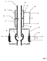
- a first embodiment of a joint is shown as a schematic cross section.
- the joint comprises an inner pipe segment 21 and an outer pipe segment 22. These pipe segments 21, 22 may move relative each other in an axial direction of the pipe segments when the joint is activated.
- the inner pipe segment 21 is the moved relatively out of the outer pipe segment 22, thereby extending the length of the joint.
- the inner pipe segment 21 is at one end configured to be attached to a part of a riser.
- the outer pipe segment 22 is also at one end, positioned on an opposite side of the joint, configured to be connected to another part of a riser.
- An inner passage through the two pipe segments 21, 22 will in a connected state, forms a continuing passage with the internal passage in the riser.
- This inner passage through the pipe segments 21, 22 may be in line with the passage in the riser.
- the inner and outer pipe segments 21, 22 are configured such that there is formed a chamber 23 between them. This is for instance formed by having end flange parts formed by the outer pipe segment, as indicated in fig. 2 but a skilled person will understand that there are other ways to form a chamber between the two pipe segments.
- a piston 24 is radially extending in the chamber 23 and thereby in abutment against both the inner pipe segment 21 and the outer pipe segment 22, and fixed relative one of the pipe segments.
- This piston 24 divides the chamber 23 in a first chamber part 25 and a second chamber part 26.
- the piston 24 is also so arranged that it when the pipe segments 21, 22 are moved relatively each other one of the chamber parts will decrease in size and one will increase in size.
- the chamber part which decreases in size is according to the invention adapted to be filled with a mainly incompressible fluid and is during use filled with this incompressible fluid, which when the fluid is kept within this chamber part will due to its incompressibility prevent the pipe segments from relative movement in one direction, even with increased tension in the riser. This tension will be transferred to a pressure in the incompressible fluid in the one chamber part.
- a fluid line connection 30 between the first chamber part 25 and the second chamber part 26.
- a burst disk 31 in this fluid line connection 30.
- This burst disk 31 is configured to brake at a given pressure in the one chamber part 25 which will decrease in size when the inner pipe segment 21 is moved out of the outer pipe segment 22. This given pressure thereby forms a threshold value.
- the flex joint comprises an inner pipe segment and an outer pipe segment configured such that center axis of the two pipe segments are allowed to form an angle between them. This will allow some angular deviation of the centre axis of one of the pipe segments relative the centre axis of the other pipe segment, other than keeping the pipe segments aligned.
- One possible configuration is shown in fig. 2 , where one pipe segments on one end is formed with a seat, partly similar to a sphere, for an end of the other pipe segments, having a complementary shape.
- This flex joint may be formed with control means for controlling when the two pipe segments are allowed to form a relative angular deviation from an alignment. There are formed operating arms 51 on both pipe segments.
- These operating arms are linked to a cylinder arrangement on opposite sides of the cylinder arrangements for the different pipe segments.
- One pipe segment is linked to the cylinder of the cylinder arrangement and the other pipe segment is linked to a piston arranged in the cylinder in the cylinder arrangement.
- the flex joint is thereby allowed to deviate at a given pressure, and one may also control the rate for how fast the pipe segments are allowed to deviate by the dimension of the fluid connection line and the opening formed by the burst disk.
- valve 55 there is instead of the burst disk in the fluid line arranged a valve 55.
- pressure sensors 33b, 33c may be arranged in the different chamber parts in the cylinder arrangement and these may be used to operate the valve 55 in the fluid line.
- the fluid line connection 30 between the two chamber parts formed by the piston 24 between the inner pipe segment 21 and the outer pipe segment 22, comprises a valve 32.
- this valve 32 may be controlled by a control module 34, which operates the valve as a response to signals received from a sensor 33 reading the tension in the riser. Possibly the sensors 33b, 33c in the stress joint may also be giving information about the angular stress in the riser to the control module for input in the operation of the valve.
- the control module 34 may also be linked to the valve 55 in the flex joint.
- the control module may also control the operation of the valve 55 in the flex joint.
- the inner and outer pipe segments 21, 22 are formed such that they allow extension in the joint by for instance having an extension of the inner pipe segment 21 on the opposite side of the chamber parts.
- sealing elements between the different parts in the joint as is the case in all the embodiment.
- the piston 24 may as shown in this embodiment be connected to the inner pipe segment 21. In an alternative embodiment the piston 24 may be connected to the outer pipe segment 22.
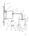
- valve 32 in the fluid line connection 30 between the two chamber parts formed between the inner and outer pipe segments 21, 22 is mechanically operated.
- a fluid line 35a from the one chamber part where this fluid line extends to one cylinder arrangement 36 and one side of a piston 37 arranged in a cylinder 38, forming the cylinder arrangement 36.
- the piston 37 is connected to a piston rod 39.
- This piston rod 39 is attached to a lever arm 40 which is allowed to move relative a fulcrum 41.
- the arrangement in this embodiment is also compensated with regards to pressure of the fluid within the riser. This is done by having a fluid line 35b extending from the internal passage of the riser or joint and to a cylinder arrangement 36b similar to the other cylinder arrangement 36a. The pressure of the fluid within the riser acts on this cylinder arrangement 36b, which through the piston 37b and piston rod 39b act on the lever arm 40, however in the opposite direction of the influence of the other cylinder arrangement 36a. The piston rod 39b is connected to the lever arm 40 on the other side of the fulcrum. As the pressure of the fluid within the riser increases the pressure on the lever arm 40 increases giving that there need to be a larger pressure within the chamber part before the valve 32 is opened.
- pressure intensifiers 44 in the fluid lines 35a, 35b.
- the system may be formed without the pressure intensifiers 44.
- the system may be formed without the fluid line 35b transferring the force from the fluid within the riser to the lever arm 40.
- a fourth embodiment of the joint In fig. 5 there is shown a fourth embodiment of the joint. Only different features from the third embodiment will be described.
- the fluid lines 35a and 35b from the fluid within the chamber part and the fluid within the riser respectively are connected to a common cylinder arrangement 36.
- the fluid line 35a from the chamber part leads to one side of a piston 37 in a cylinder 38 and the fluid line 35b from the riser lead to the opposite side of the piston 37.
- the piston 37 comprises a piston rod 39 linked to an operating arm 43 for operation of a valve 32.
- a spring element 42 is also arranged to provide a pretension on the piston 37.
- the spring element 42 is arranged within the cylinder 38. It is possible to envisage the spring element 42 arranged in connection with the operating arm but outside the cylinder arrangement.
- the operating arm 43 is in this embodiment connected to a sliding valve element 320 which slides in a valve housing 321 to close or open the fluid connection line between the two chamber parts formed between the inner and outer pipe segment 21,22.
- riser In addition to the joint as explained above there is the possibility of providing the riser with a special riser weak link, as shown in fig. 6 and which will be described below.
- a riser weak link is typically situated above two standard joints above a lower taper stress joint where the bending moment is low.
- the weak link is located above the barrier elements.
- the failure mode of the weak link may be to excessive tension as shown in US 5951061 , excessive bending as shown in NO 321184 or a combination of both. As discussed above there are different elements that induce tension in the riser, external forces or internal pressure within the riser.
- a weak link comprises two pipe segment joined by an element configured to brake at a given tension in the pipe segments, for thereby separating the two pipe segments.
- the two pipe segments are at their opposite ends, in use, connected to respective riser parts.
- the riser weak link comprises a preload package, which is connected to the respective riser segments, and configures such that the preload package can induce a tension across the weak link. This induces tension may be added independent on the tension in the riser as a whole.
- the riser weak link to brake at a predetermined tension, which equals an external added tension by regulating the preload package according to any internal pressure in the riser.
- the braking tension will be a tension in the riser from any internal fluid or added by the preload package when the internal pressure in the riser is below the design pressure and the external added pressure.
- the preload package ay be turned off, i.e. not applying any tension to the riser weak link.
- riser weak link will brake at a given external tension applied to the riser, independent of the internal pressure in the riser.
- Such a solution also gives the possibility to have an "active" riser weak link, where one by using the preload package may apply tension to the weak link so that it brakes. One can then actively decide when the weak link should brake.
- the riser weak link comprises a first pipe segment 101 and a second pipe segment 102 connected by a break element 103.
- the pipe segments 101,102 are provided with flange sections 104,105 where between a preload package 106 is arranged.
- the preload package 106 comprises in this embodiment a piston 107, cylinder 108 arrangement each connected to respective pipe segments 101,102 and a control system 109 providing pressurized fluid into the piston/cylinder arrangement.
- the piston/cylinder arrangement thereby provides a tension across the weak link. By controlling the piston/cylinder arrangement the tension across the weak link is controlled.
- there are other possibilities for providing a preload package one may use hydraulic force as explained, springs, thermal expansion, electric coil/magnet system, combinations or similar.
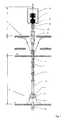
- a riser 1 with a joint 20, according to the invention forming part of the riser extending from a subsea installation 2 arranged at the seabed to a floating unit 3.
- a subsea tree 9 and an emergency disconnect package 7 close to the seabed, and the joint 20 according to the invention between the emergency disconnect package 7 and a connection point for a tension system connected between the riser 1 and the floating unit 3.
- a surface BOP 12 and a telescopic joint 11 or slip joint in the upper part of the riser 1.
- the telescopic joint 11 is arranged above the connection of the tension system to the riser.
- the joint 20 is through signal line 61 connected to a control unit 60.
- the signal or signals transmitted from the joint to the control unit 60 may represent the pressure of the fluid in the riser, within the chambers of the joint, the extension of the joint, the stress in the riser or other values in relation to the operation of the joint.
- the signal transmission between the control unit 60 and the joint 20 may also be wireless.
- This control unit 60 receives signals from the joint 20 and these signals may be communicated to an operator.
- the control unit 60 is also in communication with the emergency disconnect package 7, possibly through signal lines 62. When the signal from the joint 20 reaches a given value the control unit 60 will as a consequence of this activate the emergency disconnect package 7.
- the signal may be a representation of the extension of the joint 20, and when a given extension is reached then the emergency disconnect package 7 is activated.
- the control unit 60 may also receive signals from other parts of the riser, as indicated with signal lines 64, 63. These other signals may also be input to the processes in the control unit 60, which decides to activate the emergency disconnect package 7 or not or they may be transmitted to the operator.
Landscapes
- Engineering & Computer Science (AREA)
- Geology (AREA)
- Life Sciences & Earth Sciences (AREA)
- Mining & Mineral Resources (AREA)
- Physics & Mathematics (AREA)
- Environmental & Geological Engineering (AREA)
- Fluid Mechanics (AREA)
- Mechanical Engineering (AREA)
- General Life Sciences & Earth Sciences (AREA)
- Geochemistry & Mineralogy (AREA)
- Earth Drilling (AREA)
- Joints Allowing Movement (AREA)
- Other Liquid Machine Or Engine Such As Wave Power Use (AREA)
Claims (18)
- Verbindung zur Benutzung in einer Steigleitung (1), die sich zwischen einer schwimmenden Installation (3) und einer Unterwasser-Installation (2) erstreckt, aufweisend ein Innenrohrsegment (21) und ein Außenrohrsegment (22), die relativ zueinander in einer axialen Richtung beweglich und mit entsprechenden Steigleitungssegmenten verbindbar angeordnet sind, eine Kammer (23) zwischen sich mit einem sich radial erstreckenden Kolben (24) bildend, der die Kammer (23) in einen ersten Kammerteil (25) und einen zweiten Kammerteil (26) teilt, wobei mindestens einer der Kammerteile (25) in einer Anfangsstellung der Verbindung dazu ausgebildet ist, ein im Wesentlichen inkompressibles Fluid zu enthalten, wobei dieser Kammerteil (25) sein Volumen verringert, wenn das Innenrohrsegment (21) relativ aus dem zum Außenrohrsegment (22) heraus bewegt wird, dadurch gekenntzeichnet, dass die Verbindung mit einer Fluidleitungsverbindung (30) vom einem Kammerteil (25) zum anderen Kammerteil (26) ausgestattet ist, die so konfiguriert ist, dass die Relativbewegung der Rohrsegmente (21, 22) durch die erlaubte Flussrate eines aus dem Kammerteil (25) durch die Fluidverbindung (30) in den anderen Kammerteil (26) fließenden Fluids gesteuert wird.
- Verbindung nach Anspruch 1, dadurch gekennzeichnet, dass die Fluidleitungsverbindung (30) eine Berstscheibe (31) aufweist.
- Verbindung nach einen der vorangehenden Ansprüche, dadurch gekennzeichnet, dass die Fluidleitungsverbindung (30) ein Drosselventil (32) aufweist.
- Verbindung nach Anspruch 3, dadurch gekennzeichnet, dass sie eine Steuereinrichtung (34) aufweist, die mit einem Sensor (33) zum Lesen der Spannung in der Steigleitung (1) verbunden ist und dass die Steuereinrichtung (34) im Ansprechen auf die Sensor-Auslesungen das Drosselventil (32) betätigt.
- Verbindung nach einem der vorangehenden Ansprüche, dadurch gekennzeichnet, dass sie derart konfiguriert ist, dass der Druck innerhalb des einen Kammerteils (25) auf eine mechanische Steuereinrichtung (36, 40, 43) zur Betätigung des Drosselventils (32) wirkt.
- Verbindung nach Anspruch 5, dadurch gekennzeichnet, dass sie eine Fluidleitung (35a), von dem einen Kammerteil (25) zur einer Kolbenanordnung (36, 36a) aufweist, wobei die Kolbenanordnung (36, 36a) im Ansprechen auf den Fluiddruck im Kammerteil arbeitet und auf einen Betätigungsarm (43) zur Betätigung des Ventils (32) wirkt.
- Verbindung nach Anspruch 5 oder 6, dadurch gekennzeichnet, dass sie derart konfiguriert ist, dass der Druck innerhalb eines Flussweges durch die Verbindung auf eine mechanische Steuereinrichtung (36, 40, 43) zur Betätigung des Drosselventils (32) wirkt.
- Verbindung nach Anspruch 7, dadurch gekennzeichnet, dass sie eine Fluidleitung (35b) vom Flussweg durch die Verbindung zu einer Kolbenanordnung (36, 36b) aufweist, wobei die Kolbenanordnung (36, 36b) im Ansprechen auf den Fluiddruck im Flussweg arbeitet und auf einen Betätigungsarm (43) zur Betätigung des Ventils (32) wirkt.
- Verbindung nach Anspruch 6 und 8, dadurch gekennzeichnet, dass die Kolbenanordnung zwei Zylinder (38a, 38b) mit Kolben (37a, 37b) mit einer Kolbenstange (39a, 39b) aufweist, die mit entsprechenden Fluidleitungen (35a, 35b) verbunden sind und dass der Betätigungsarm (43) einen Hebelarm (40) aufweist, wobei die distalen Enden der beiden Kolbenstangen (39a, 39b) auf den Hebelarm (40) wirken, um den Hebelarm (40) in entgegengesetzte Richtungen relativ zu einem Hebelstützpunkt (41) zu bewegen.
- Verbindung nach einem der Ansprüche 6, 8 oder 9, dadurch gekennzeichnet, dass mindestens eine der Fluidleitungen (35a, 35b) zwischen dem Kammerteil (25) und der Kolbenanordnung (36, 36a) oder der Verbindung und der Kolbenanordnung (36, 36b) als Druckverstärker (44) ausgebildet ist.
- Verbindung nach einem der Ansprüche 6, 8, 9 oder 10, dadurch gekennzeichnet, dass mindestens einer der Kolbenanordnung (36, 36a, 36b) durch Federelemente (42) vorgespannt ist.
- Steigleitung (1), die sich zwischen einer schwimmenden Installation (3) und einer Unterwasserinstallation (2) erstreckt, aufweisend einen Not-Schnellabschaltpack (EQDP) (7), dadurch gekennzeichnet, dass eine Verbindung (20) nach einem der Ansprüche 1 bis 11 einen Teil der Steigleitung (1) zwischen der schwimmenden Installation (3) und dem EQDP (7) bildet.
- Steigleitung nach Anspruch 12, dadurch gekennzeichnet, dass ein Flex-Gelenk (50) zwischen dem EQDP (7) und der Verbindung (20) angeordnet ist.
- Steigleitung nach Anspruch 12 oder 13, dadurch gekennzeichnet, dass sie eine Steuereinheit (60) aufweist, die mit der Verbindung (20) und dem EQDP (7) verbunden und konfiguriert ist, mindestens Signale von der Verbindung (20) zu empfangen, diese zu verarbeiten und Signale an den EQDP (7) zu senden.
- Steigleitung nach Anspruch 14, dadurch gekennzeichnet, dass die Steuereinheit (60) auch Signale von anderen Teilen der Steigleitung (1) empfängt.
- Steigleitung nach einem der Ansprüche 12 bis 15 mit einer Verbindung nach Anspruch 4, dadurch gekenntzeichnet, dass die Steuereinrichtung (34) auch Signale von Sensoren (33b,c in Verbindung mit dem Flex-Gelenk (50) empfängt.
- Steigleitung nach Anspruch 16, dadurch gekennzeichnet, dass die Steuereinrichtung (34) mit der Steuereinheit (60) verbunden ist oder einen Teil dieser bildet.
- Verfahren zur Vergrößerung des Betriebsfensters einer Steigleitung (1), die sich zwischen einer schwimmenden Installation (3) und einer Unterwasser-Installation (2) erstreckt, bereitstellend eine Verbindung gemäß einem der Ansprüche 1 bis 11 zwischen der schwimmenden Installation (3) und dem EQPD (7), wenn die schwimmende Installation (3) von ihrem Betriebsfenster abweicht und dadurch die Spannung in der Steigleitung (1) steigt, Steuern des Ausströmens von Fluid aus dem Kammerteil (25) und dadurch Steuern der Ausdehnungsrate der Verbindung, hierdurch vergrößernd die verfügbare Zeit zur Freigabe des EQDP (7).
Priority Applications (2)
| Application Number | Priority Date | Filing Date | Title |
|---|---|---|---|
| DK14193668.2T DK2863005T3 (en) | 2009-02-09 | 2010-02-05 | Shutter Connection |
| EP14193668.2A EP2863005B1 (de) | 2009-02-09 | 2010-02-05 | Auslöserverbindung |
Applications Claiming Priority (2)
| Application Number | Priority Date | Filing Date | Title |
|---|---|---|---|
| NO20090607A NO329804B1 (no) | 2009-02-09 | 2009-02-09 | Kobling for bruk i et stigeror, stigeror med en slik kobling og fremgangsmate for a oke operasjonsvinduet til et stigeror |
| PCT/NO2010/000044 WO2010090531A1 (en) | 2009-02-09 | 2010-02-05 | Trigger joint |
Related Child Applications (2)
| Application Number | Title | Priority Date | Filing Date |
|---|---|---|---|
| EP14193668.2A Division-Into EP2863005B1 (de) | 2009-02-09 | 2010-02-05 | Auslöserverbindung |
| EP14193668.2A Division EP2863005B1 (de) | 2009-02-09 | 2010-02-05 | Auslöserverbindung |
Publications (2)
| Publication Number | Publication Date |
|---|---|
| EP2394017A1 EP2394017A1 (de) | 2011-12-14 |
| EP2394017B1 true EP2394017B1 (de) | 2015-06-24 |
Family
ID=42224774
Family Applications (2)
| Application Number | Title | Priority Date | Filing Date |
|---|---|---|---|
| EP14193668.2A Revoked EP2863005B1 (de) | 2009-02-09 | 2010-02-05 | Auslöserverbindung |
| EP10703708.7A Active EP2394017B1 (de) | 2009-02-09 | 2010-02-05 | Auslöserverbindung |
Family Applications Before (1)
| Application Number | Title | Priority Date | Filing Date |
|---|---|---|---|
| EP14193668.2A Revoked EP2863005B1 (de) | 2009-02-09 | 2010-02-05 | Auslöserverbindung |
Country Status (9)
| Country | Link |
|---|---|
| US (1) | US8875794B2 (de) |
| EP (2) | EP2863005B1 (de) |
| AU (1) | AU2010211446B2 (de) |
| CA (1) | CA2751446C (de) |
| DK (1) | DK2863005T3 (de) |
| NO (1) | NO329804B1 (de) |
| RU (1) | RU2516352C2 (de) |
| SG (1) | SG173575A1 (de) |
| WO (1) | WO2010090531A1 (de) |
Families Citing this family (24)
| Publication number | Priority date | Publication date | Assignee | Title |
|---|---|---|---|---|
| CN101980738A (zh) | 2008-02-07 | 2011-02-23 | 华盛顿大学 | 圆周气雾设备 |
| NO333849B1 (no) * | 2010-04-28 | 2013-09-30 | Statoil Petroleum As | Sikkerhetsanordning og fremgangsmåte for beskyttelse av brønnbarrieren. |
| NO338526B1 (no) * | 2010-11-30 | 2016-08-29 | Vetco Gray Scandinavia As | Sikkerhetskobling samt stigerør som omfatter en slik sikkerhetskobling |
| RU2612506C2 (ru) | 2011-03-03 | 2017-03-09 | Импел Ньюрофарма Инк. | Устройство для назальной доставки лекарственных средств |
| WO2012154859A1 (en) | 2011-05-09 | 2012-11-15 | Impel Neuropharma Inc. | Nozzles for nasal drug delivery |
| NO345526B1 (no) * | 2011-11-18 | 2021-03-29 | Statoil Petroleum As | Svakt ledd i stigerør |
| WO2013154566A1 (en) * | 2012-04-12 | 2013-10-17 | Eaton Corporation | Plunger-type wire riser tensioner |
| NO339117B1 (no) * | 2013-01-08 | 2016-11-14 | Fmc Kongsberg Subsea As | Teleskopisk stigerørsskjøt. |
| NO335378B1 (no) | 2013-01-08 | 2014-12-08 | Fmc Kongsberg Subsea As | sikkerhetsskjøt |
| EP2991713B1 (de) | 2013-04-28 | 2019-06-19 | Impel Neuropharma Inc. | Medizinischer einzeldosisbehälter |
| RU2566162C1 (ru) * | 2014-10-31 | 2015-10-20 | Общество с ограниченной ответственностью "ТюменНИИгипрогаз" | Морская скважина для добычи нефти и газа с надводным размещением устьевого оборудования |
| NZ741171A (en) | 2015-09-10 | 2022-01-28 | Impel Neuropharma Inc | In-line nasal delivery device |
| EP3420176A4 (de) * | 2016-02-22 | 2019-10-30 | Safelink AS | Mobiler hubkompensator für unterseeische umgebung |
| WO2017146591A2 (en) | 2016-02-22 | 2017-08-31 | Safelink As | Mobile active heave compensator |
| EP3713628A4 (de) | 2017-11-21 | 2021-08-18 | Impel Neuropharma Inc. | Intranasale vorrichtung mit tauchrohr |
| CA3081680A1 (en) | 2017-11-21 | 2019-05-31 | Impel Neuropharma, Inc. | Intranasal device with inlet interface |
| JP7317020B2 (ja) | 2018-01-05 | 2023-07-28 | インペル ファーマシューティカルズ インコーポレイテッド | 精密嗅覚デバイスによるジヒドロエルゴタミンの鼻腔内送達 |
| US11278492B2 (en) | 2018-01-05 | 2022-03-22 | Impel Neuropharma, Inc. | Intranasal delivery of olanzapine by precision olfactory device |
| JP2021532098A (ja) | 2018-07-19 | 2021-11-25 | インペル ニューロファーマ インコーポレイテッド | パーキンソン病の治療のためのレボドパおよびドーパデカルボキシラーゼ阻害剤の呼吸管路送達 |
| AU2019418744B2 (en) | 2019-01-03 | 2023-08-03 | Impel Pharmaceuticals Inc. | Nasal drug delivery device |
| BR112021023049A8 (pt) | 2019-05-17 | 2022-10-18 | Impel Neuropharma Inc | Dispositivo de dispensação nasal de uso único |
| RU2703892C1 (ru) * | 2019-06-27 | 2019-10-22 | Общество с ограниченной ответственностью "Газпром 335" | Соединительный узел райзера |
| CN110576941B (zh) * | 2019-09-25 | 2021-03-02 | 大连理工大学 | 一种具有电磁阻尼的被动式波浪补偿装置 |
| GB202107620D0 (en) * | 2021-05-28 | 2021-07-14 | Expro North Sea Ltd | Control system for a well control device |
Family Cites Families (28)
| Publication number | Priority date | Publication date | Assignee | Title |
|---|---|---|---|---|
| US3643751A (en) | 1969-12-15 | 1972-02-22 | Charles D Crickmer | Hydrostatic riser pipe tensioner |
| US3647245A (en) * | 1970-01-16 | 1972-03-07 | Vetco Offshore Ind Inc | Telescopic joint embodying a pressure-actuated packing device |
| US4049239A (en) * | 1975-12-08 | 1977-09-20 | Exxon Production Research Company | Drill spring tension limiting device for floating drilling vessels |
| GB1526239A (en) * | 1975-12-30 | 1978-09-27 | Shell Int Research | Marine riser system and method for installing the same |
| US4361165A (en) | 1980-08-07 | 1982-11-30 | Exxon Research And Engineering Co. | Breakaway pipe coupling with automatically closed valves |
| US4371038A (en) * | 1980-12-08 | 1983-02-01 | Otis Engineering Corporation | Apparatus and method for injecting fluid into a well |
| US4367981A (en) | 1981-06-29 | 1983-01-11 | Combustion Engineering, Inc. | Fluid pressure-tensioned slip joint for drilling riser |
| US4424988A (en) | 1981-12-28 | 1984-01-10 | Consumers' Gas Company Limited | Frangible pipe coupling |
| CA1205740A (en) * | 1982-03-05 | 1986-06-10 | Hydra-Rig, Inc. | Marine riser tensioner |
| JPS59177494A (ja) * | 1983-03-29 | 1984-10-08 | 工業技術院長 | ライザ用テレスコピツクジヨイント |
| US4712620A (en) * | 1985-01-31 | 1987-12-15 | Vetco Gray Inc. | Upper marine riser package |
| NO169027C (no) * | 1988-11-09 | 1992-04-29 | Smedvig Ipr As | Bevegelseskompensator for stigeroer |
| NO302493B1 (no) * | 1996-05-13 | 1998-03-09 | Maritime Hydraulics As | Glideskjöt |
| US5951061A (en) | 1997-08-13 | 1999-09-14 | Continental Emsco Company | Elastomeric subsea flex joint and swivel for offshore risers |
| US5978739A (en) | 1997-10-14 | 1999-11-02 | Stockton; Thomas R. | Disconnect information and monitoring system for dynamically positioned offshore drilling rigs |
| US6017168A (en) | 1997-12-22 | 2000-01-25 | Abb Vetco Gray Inc. | Fluid assist bearing for telescopic joint of a RISER system |
| US6913092B2 (en) * | 1998-03-02 | 2005-07-05 | Weatherford/Lamb, Inc. | Method and system for return of drilling fluid from a sealed marine riser to a floating drilling rig while drilling |
| WO2004113158A2 (en) | 2001-11-06 | 2004-12-29 | Worldwide Oilfield Machine, Inc. | Lightweight and compact subsea intervention package and method |
| GB2391889A (en) | 2001-04-30 | 2004-02-18 | Shell Int Research | Subsea drilling riser disconnect system and method |
| EP1319800B1 (de) * | 2001-12-12 | 2006-02-22 | Cooper Cameron Corporation | System zur Positionsdetektion für eine Einrichtung im Bohrloch |
| ES2297124T3 (es) | 2002-02-01 | 2008-05-01 | Seadrill Management As | Mecanismo de accionamiento para desconectar un elevador de un conector de elevador. |
| US20050100414A1 (en) | 2003-11-07 | 2005-05-12 | Conocophillips Company | Composite riser with integrity monitoring apparatus and method |
| NO322172B1 (no) * | 2004-05-21 | 2006-08-21 | Fmc Kongsberg Subsea As | Anordning i forbindelse med hivkompensering av et trykksatt stigeror forlopende mellom en havbunnsinstallasjon og en flytende enhet. |
| NO321184B1 (no) | 2004-09-02 | 2006-04-03 | Fmc Kongsberg Subsea As | Anordning for sikkerhetsskjot for et ror |
| NO327932B1 (no) * | 2006-10-27 | 2009-10-26 | Fmc Kongsberg Subsea As | Teleskopskjot |
| US7926579B2 (en) | 2007-06-19 | 2011-04-19 | Schlumberger Technology Corporation | Apparatus for subsea intervention |
| NO328634B1 (no) * | 2008-02-13 | 2010-04-12 | Fmc Kongsberg Subsea As | Ledd for anvendelse sammen med et stigeror, stigeror med slikt ledd og fremgangsmate for a redusere boyemomenter i et stigeror |
| NO333681B1 (no) * | 2009-01-08 | 2013-08-12 | Aker Subsea As | Undervanns tilleggskompensator |
-
2009
- 2009-02-09 NO NO20090607A patent/NO329804B1/no not_active IP Right Cessation
-
2010
- 2010-02-05 RU RU2011136553/03A patent/RU2516352C2/ru active
- 2010-02-05 AU AU2010211446A patent/AU2010211446B2/en active Active
- 2010-02-05 DK DK14193668.2T patent/DK2863005T3/en active
- 2010-02-05 CA CA2751446A patent/CA2751446C/en active Active
- 2010-02-05 EP EP14193668.2A patent/EP2863005B1/de not_active Revoked
- 2010-02-05 WO PCT/NO2010/000044 patent/WO2010090531A1/en not_active Ceased
- 2010-02-05 SG SG2011056728A patent/SG173575A1/en unknown
- 2010-02-05 US US13/138,371 patent/US8875794B2/en active Active
- 2010-02-05 EP EP10703708.7A patent/EP2394017B1/de active Active
Also Published As
| Publication number | Publication date |
|---|---|
| AU2010211446B2 (en) | 2015-07-16 |
| US20120031622A1 (en) | 2012-02-09 |
| SG173575A1 (en) | 2011-09-29 |
| EP2863005B1 (de) | 2015-12-23 |
| EP2863005A1 (de) | 2015-04-22 |
| CA2751446C (en) | 2016-10-18 |
| RU2011136553A (ru) | 2013-03-20 |
| AU2010211446A1 (en) | 2011-08-25 |
| DK2863005T3 (en) | 2016-03-29 |
| NO329804B1 (no) | 2010-12-20 |
| EP2394017A1 (de) | 2011-12-14 |
| NO20090607L (no) | 2010-08-10 |
| WO2010090531A1 (en) | 2010-08-12 |
| CA2751446A1 (en) | 2010-08-12 |
| US8875794B2 (en) | 2014-11-04 |
| RU2516352C2 (ru) | 2014-05-20 |
Similar Documents
| Publication | Publication Date | Title |
|---|---|---|
| EP2863005B1 (de) | Auslöserverbindung | |
| AU2014204959B2 (en) | Safety joint | |
| US10001220B2 (en) | Pipeline isolation check plug | |
| JP7102398B2 (ja) | 油圧式係留索保持装置、システム及び方法 | |
| WO2011135021A2 (en) | Electronic combined load weak link | |
| US9915372B2 (en) | High integrity pressure protecting system (HIPPS) for a fluid line | |
| US8393397B2 (en) | Apparatus and method for separating a tubular string from a subsea well installation | |
| WO2013137743A1 (en) | Device for compensation of wave influenced distance variations on a drill string | |
| US10156113B2 (en) | BOP control system circuit to reduce hydraulic flow/water hammer | |
| AU2015201236B2 (en) | Trigger joint | |
| NO20171771A1 (en) | Riser pressure relief apparatus | |
| EP3992505A1 (de) | Vorrichtung zur steuerung eines ventils | |
| NO327464B1 (no) | Stigerorsystem | |
| WO2016122774A1 (en) | Well flow control assemblies and associated methods | |
| WO2007069905A2 (en) | Smart compensator |
Legal Events
| Date | Code | Title | Description |
|---|---|---|---|
| PUAI | Public reference made under article 153(3) epc to a published international application that has entered the european phase |
Free format text: ORIGINAL CODE: 0009012 |
|
| 17P | Request for examination filed |
Effective date: 20110909 |
|
| AK | Designated contracting states |
Kind code of ref document: A1 Designated state(s): AT BE BG CH CY CZ DE DK EE ES FI FR GB GR HR HU IE IS IT LI LT LU LV MC MK MT NL NO PL PT RO SE SI SK SM TR |
|
| RIN1 | Information on inventor provided before grant (corrected) |
Inventor name: JOHANSEN, JOHN, A. Inventor name: CARLSEN, TOR-OYSTEIN Inventor name: CARLSEN, HANS, PAUL |
|
| DAX | Request for extension of the european patent (deleted) | ||
| GRAP | Despatch of communication of intention to grant a patent |
Free format text: ORIGINAL CODE: EPIDOSNIGR1 |
|
| INTG | Intention to grant announced |
Effective date: 20150123 |
|
| GRAS | Grant fee paid |
Free format text: ORIGINAL CODE: EPIDOSNIGR3 |
|
| GRAA | (expected) grant |
Free format text: ORIGINAL CODE: 0009210 |
|
| AK | Designated contracting states |
Kind code of ref document: B1 Designated state(s): AT BE BG CH CY CZ DE DK EE ES FI FR GB GR HR HU IE IS IT LI LT LU LV MC MK MT NL NO PL PT RO SE SI SK SM TR |
|
| REG | Reference to a national code |
Ref country code: GB Ref legal event code: FG4D |
|
| REG | Reference to a national code |
Ref country code: CH Ref legal event code: EP |
|
| REG | Reference to a national code |
Ref country code: AT Ref legal event code: REF Ref document number: 732964 Country of ref document: AT Kind code of ref document: T Effective date: 20150715 |
|
| REG | Reference to a national code |
Ref country code: IE Ref legal event code: FG4D |
|
| REG | Reference to a national code |
Ref country code: DE Ref legal event code: R096 Ref document number: 602010025406 Country of ref document: DE |
|
| PG25 | Lapsed in a contracting state [announced via postgrant information from national office to epo] |
Ref country code: FI Free format text: LAPSE BECAUSE OF FAILURE TO SUBMIT A TRANSLATION OF THE DESCRIPTION OR TO PAY THE FEE WITHIN THE PRESCRIBED TIME-LIMIT Effective date: 20150624 Ref country code: HR Free format text: LAPSE BECAUSE OF FAILURE TO SUBMIT A TRANSLATION OF THE DESCRIPTION OR TO PAY THE FEE WITHIN THE PRESCRIBED TIME-LIMIT Effective date: 20150624 Ref country code: LT Free format text: LAPSE BECAUSE OF FAILURE TO SUBMIT A TRANSLATION OF THE DESCRIPTION OR TO PAY THE FEE WITHIN THE PRESCRIBED TIME-LIMIT Effective date: 20150624 |
|
| REG | Reference to a national code |
Ref country code: NO Ref legal event code: T2 Effective date: 20150624 |
|
| REG | Reference to a national code |
Ref country code: AT Ref legal event code: MK05 Ref document number: 732964 Country of ref document: AT Kind code of ref document: T Effective date: 20150624 |
|
| REG | Reference to a national code |
Ref country code: LT Ref legal event code: MG4D |
|
| PG25 | Lapsed in a contracting state [announced via postgrant information from national office to epo] |
Ref country code: BG Free format text: LAPSE BECAUSE OF FAILURE TO SUBMIT A TRANSLATION OF THE DESCRIPTION OR TO PAY THE FEE WITHIN THE PRESCRIBED TIME-LIMIT Effective date: 20150924 Ref country code: GR Free format text: LAPSE BECAUSE OF FAILURE TO SUBMIT A TRANSLATION OF THE DESCRIPTION OR TO PAY THE FEE WITHIN THE PRESCRIBED TIME-LIMIT Effective date: 20150925 Ref country code: LV Free format text: LAPSE BECAUSE OF FAILURE TO SUBMIT A TRANSLATION OF THE DESCRIPTION OR TO PAY THE FEE WITHIN THE PRESCRIBED TIME-LIMIT Effective date: 20150624 |
|
| REG | Reference to a national code |
Ref country code: NL Ref legal event code: MP Effective date: 20150624 |
|
| REG | Reference to a national code |
Ref country code: FR Ref legal event code: PLFP Year of fee payment: 7 |
|
| PG25 | Lapsed in a contracting state [announced via postgrant information from national office to epo] |
Ref country code: EE Free format text: LAPSE BECAUSE OF FAILURE TO SUBMIT A TRANSLATION OF THE DESCRIPTION OR TO PAY THE FEE WITHIN THE PRESCRIBED TIME-LIMIT Effective date: 20150624 |
|
| PG25 | Lapsed in a contracting state [announced via postgrant information from national office to epo] |
Ref country code: IS Free format text: LAPSE BECAUSE OF FAILURE TO SUBMIT A TRANSLATION OF THE DESCRIPTION OR TO PAY THE FEE WITHIN THE PRESCRIBED TIME-LIMIT Effective date: 20151024 Ref country code: AT Free format text: LAPSE BECAUSE OF FAILURE TO SUBMIT A TRANSLATION OF THE DESCRIPTION OR TO PAY THE FEE WITHIN THE PRESCRIBED TIME-LIMIT Effective date: 20150624 Ref country code: RO Free format text: LAPSE BECAUSE OF NON-PAYMENT OF DUE FEES Effective date: 20150624 Ref country code: PL Free format text: LAPSE BECAUSE OF FAILURE TO SUBMIT A TRANSLATION OF THE DESCRIPTION OR TO PAY THE FEE WITHIN THE PRESCRIBED TIME-LIMIT Effective date: 20150624 Ref country code: SK Free format text: LAPSE BECAUSE OF FAILURE TO SUBMIT A TRANSLATION OF THE DESCRIPTION OR TO PAY THE FEE WITHIN THE PRESCRIBED TIME-LIMIT Effective date: 20150624 Ref country code: CZ Free format text: LAPSE BECAUSE OF FAILURE TO SUBMIT A TRANSLATION OF THE DESCRIPTION OR TO PAY THE FEE WITHIN THE PRESCRIBED TIME-LIMIT Effective date: 20150624 Ref country code: ES Free format text: LAPSE BECAUSE OF FAILURE TO SUBMIT A TRANSLATION OF THE DESCRIPTION OR TO PAY THE FEE WITHIN THE PRESCRIBED TIME-LIMIT Effective date: 20150624 Ref country code: PT Free format text: LAPSE BECAUSE OF FAILURE TO SUBMIT A TRANSLATION OF THE DESCRIPTION OR TO PAY THE FEE WITHIN THE PRESCRIBED TIME-LIMIT Effective date: 20151026 |
|
| REG | Reference to a national code |
Ref country code: DE Ref legal event code: R097 Ref document number: 602010025406 Country of ref document: DE |
|
| PG25 | Lapsed in a contracting state [announced via postgrant information from national office to epo] |
Ref country code: DK Free format text: LAPSE BECAUSE OF FAILURE TO SUBMIT A TRANSLATION OF THE DESCRIPTION OR TO PAY THE FEE WITHIN THE PRESCRIBED TIME-LIMIT Effective date: 20150624 |
|
| PLBE | No opposition filed within time limit |
Free format text: ORIGINAL CODE: 0009261 |
|
| STAA | Information on the status of an ep patent application or granted ep patent |
Free format text: STATUS: NO OPPOSITION FILED WITHIN TIME LIMIT |
|
| PG25 | Lapsed in a contracting state [announced via postgrant information from national office to epo] |
Ref country code: BE Free format text: LAPSE BECAUSE OF NON-PAYMENT OF DUE FEES Effective date: 20160229 |
|
| 26N | No opposition filed |
Effective date: 20160329 |
|
| PG25 | Lapsed in a contracting state [announced via postgrant information from national office to epo] |
Ref country code: SI Free format text: LAPSE BECAUSE OF FAILURE TO SUBMIT A TRANSLATION OF THE DESCRIPTION OR TO PAY THE FEE WITHIN THE PRESCRIBED TIME-LIMIT Effective date: 20150624 |
|
| REG | Reference to a national code |
Ref country code: DE Ref legal event code: R119 Ref document number: 602010025406 Country of ref document: DE |
|
| PG25 | Lapsed in a contracting state [announced via postgrant information from national office to epo] |
Ref country code: MC Free format text: LAPSE BECAUSE OF FAILURE TO SUBMIT A TRANSLATION OF THE DESCRIPTION OR TO PAY THE FEE WITHIN THE PRESCRIBED TIME-LIMIT Effective date: 20150624 Ref country code: LU Free format text: LAPSE BECAUSE OF FAILURE TO SUBMIT A TRANSLATION OF THE DESCRIPTION OR TO PAY THE FEE WITHIN THE PRESCRIBED TIME-LIMIT Effective date: 20160205 |
|
| REG | Reference to a national code |
Ref country code: CH Ref legal event code: PL |
|
| PG25 | Lapsed in a contracting state [announced via postgrant information from national office to epo] |
Ref country code: CH Free format text: LAPSE BECAUSE OF NON-PAYMENT OF DUE FEES Effective date: 20160229 Ref country code: LI Free format text: LAPSE BECAUSE OF NON-PAYMENT OF DUE FEES Effective date: 20160229 |
|
| REG | Reference to a national code |
Ref country code: IE Ref legal event code: MM4A |
|
| PG25 | Lapsed in a contracting state [announced via postgrant information from national office to epo] |
Ref country code: BE Free format text: LAPSE BECAUSE OF FAILURE TO SUBMIT A TRANSLATION OF THE DESCRIPTION OR TO PAY THE FEE WITHIN THE PRESCRIBED TIME-LIMIT Effective date: 20150624 |
|
| REG | Reference to a national code |
Ref country code: FR Ref legal event code: PLFP Year of fee payment: 8 |
|
| PG25 | Lapsed in a contracting state [announced via postgrant information from national office to epo] |
Ref country code: IE Free format text: LAPSE BECAUSE OF NON-PAYMENT OF DUE FEES Effective date: 20160205 Ref country code: DE Free format text: LAPSE BECAUSE OF NON-PAYMENT OF DUE FEES Effective date: 20160901 |
|
| PG25 | Lapsed in a contracting state [announced via postgrant information from national office to epo] |
Ref country code: SE Free format text: LAPSE BECAUSE OF FAILURE TO SUBMIT A TRANSLATION OF THE DESCRIPTION OR TO PAY THE FEE WITHIN THE PRESCRIBED TIME-LIMIT Effective date: 20150624 Ref country code: NL Free format text: LAPSE BECAUSE OF FAILURE TO SUBMIT A TRANSLATION OF THE DESCRIPTION OR TO PAY THE FEE WITHIN THE PRESCRIBED TIME-LIMIT Effective date: 20150624 |
|
| PG25 | Lapsed in a contracting state [announced via postgrant information from national office to epo] |
Ref country code: MT Free format text: LAPSE BECAUSE OF FAILURE TO SUBMIT A TRANSLATION OF THE DESCRIPTION OR TO PAY THE FEE WITHIN THE PRESCRIBED TIME-LIMIT Effective date: 20150624 |
|
| REG | Reference to a national code |
Ref country code: FR Ref legal event code: PLFP Year of fee payment: 9 |
|
| PG25 | Lapsed in a contracting state [announced via postgrant information from national office to epo] |
Ref country code: CY Free format text: LAPSE BECAUSE OF FAILURE TO SUBMIT A TRANSLATION OF THE DESCRIPTION OR TO PAY THE FEE WITHIN THE PRESCRIBED TIME-LIMIT Effective date: 20150624 Ref country code: SM Free format text: LAPSE BECAUSE OF FAILURE TO SUBMIT A TRANSLATION OF THE DESCRIPTION OR TO PAY THE FEE WITHIN THE PRESCRIBED TIME-LIMIT Effective date: 20150624 Ref country code: HU Free format text: LAPSE BECAUSE OF FAILURE TO SUBMIT A TRANSLATION OF THE DESCRIPTION OR TO PAY THE FEE WITHIN THE PRESCRIBED TIME-LIMIT; INVALID AB INITIO Effective date: 20100205 |
|
| PG25 | Lapsed in a contracting state [announced via postgrant information from national office to epo] |
Ref country code: MT Free format text: LAPSE BECAUSE OF FAILURE TO SUBMIT A TRANSLATION OF THE DESCRIPTION OR TO PAY THE FEE WITHIN THE PRESCRIBED TIME-LIMIT Effective date: 20160229 Ref country code: MK Free format text: LAPSE BECAUSE OF FAILURE TO SUBMIT A TRANSLATION OF THE DESCRIPTION OR TO PAY THE FEE WITHIN THE PRESCRIBED TIME-LIMIT Effective date: 20150624 Ref country code: TR Free format text: LAPSE BECAUSE OF FAILURE TO SUBMIT A TRANSLATION OF THE DESCRIPTION OR TO PAY THE FEE WITHIN THE PRESCRIBED TIME-LIMIT Effective date: 20150624 |
|
| P01 | Opt-out of the competence of the unified patent court (upc) registered |
Effective date: 20230523 |
|
| PGFP | Annual fee paid to national office [announced via postgrant information from national office to epo] |
Ref country code: GB Payment date: 20260219 Year of fee payment: 17 |
|
| PGFP | Annual fee paid to national office [announced via postgrant information from national office to epo] |
Ref country code: NO Payment date: 20260127 Year of fee payment: 17 |
|
| PGFP | Annual fee paid to national office [announced via postgrant information from national office to epo] |
Ref country code: IT Payment date: 20260210 Year of fee payment: 17 |
|
| PGFP | Annual fee paid to national office [announced via postgrant information from national office to epo] |
Ref country code: FR Payment date: 20260227 Year of fee payment: 17 |