EP2393339A1 - Versatile microwave heating apparatus - Google Patents
Versatile microwave heating apparatus Download PDFInfo
- Publication number
- EP2393339A1 EP2393339A1 EP10164960A EP10164960A EP2393339A1 EP 2393339 A1 EP2393339 A1 EP 2393339A1 EP 10164960 A EP10164960 A EP 10164960A EP 10164960 A EP10164960 A EP 10164960A EP 2393339 A1 EP2393339 A1 EP 2393339A1
- Authority
- EP
- European Patent Office
- Prior art keywords
- microwave
- cavity
- supply system
- heating apparatus
- food
- Prior art date
- Legal status (The legal status is an assumption and is not a legal conclusion. Google has not performed a legal analysis and makes no representation as to the accuracy of the status listed.)
- Granted
Links
Images

Classifications
-
- H—ELECTRICITY
- H05—ELECTRIC TECHNIQUES NOT OTHERWISE PROVIDED FOR
- H05B—ELECTRIC HEATING; ELECTRIC LIGHT SOURCES NOT OTHERWISE PROVIDED FOR; CIRCUIT ARRANGEMENTS FOR ELECTRIC LIGHT SOURCES, IN GENERAL
- H05B6/00—Heating by electric, magnetic or electromagnetic fields
- H05B6/64—Heating using microwaves
- H05B6/647—Aspects related to microwave heating combined with other heating techniques
- H05B6/6482—Aspects related to microwave heating combined with other heating techniques combined with radiant heating, e.g. infrared heating
-
- H—ELECTRICITY
- H05—ELECTRIC TECHNIQUES NOT OTHERWISE PROVIDED FOR
- H05B—ELECTRIC HEATING; ELECTRIC LIGHT SOURCES NOT OTHERWISE PROVIDED FOR; CIRCUIT ARRANGEMENTS FOR ELECTRIC LIGHT SOURCES, IN GENERAL
- H05B6/00—Heating by electric, magnetic or electromagnetic fields
- H05B6/64—Heating using microwaves
- H05B6/6402—Aspects relating to the microwave cavity
-
- H—ELECTRICITY
- H05—ELECTRIC TECHNIQUES NOT OTHERWISE PROVIDED FOR
- H05B—ELECTRIC HEATING; ELECTRIC LIGHT SOURCES NOT OTHERWISE PROVIDED FOR; CIRCUIT ARRANGEMENTS FOR ELECTRIC LIGHT SOURCES, IN GENERAL
- H05B6/00—Heating by electric, magnetic or electromagnetic fields
- H05B6/64—Heating using microwaves
- H05B6/6447—Method of operation or details of the microwave heating apparatus related to the use of detectors or sensors
-
- H—ELECTRICITY
- H05—ELECTRIC TECHNIQUES NOT OTHERWISE PROVIDED FOR
- H05B—ELECTRIC HEATING; ELECTRIC LIGHT SOURCES NOT OTHERWISE PROVIDED FOR; CIRCUIT ARRANGEMENTS FOR ELECTRIC LIGHT SOURCES, IN GENERAL
- H05B6/00—Heating by electric, magnetic or electromagnetic fields
- H05B6/64—Heating using microwaves
- H05B6/647—Aspects related to microwave heating combined with other heating techniques
- H05B6/6491—Aspects related to microwave heating combined with other heating techniques combined with the use of susceptors
- H05B6/6494—Aspects related to microwave heating combined with other heating techniques combined with the use of susceptors for cooking
-
- H—ELECTRICITY
- H05—ELECTRIC TECHNIQUES NOT OTHERWISE PROVIDED FOR
- H05B—ELECTRIC HEATING; ELECTRIC LIGHT SOURCES NOT OTHERWISE PROVIDED FOR; CIRCUIT ARRANGEMENTS FOR ELECTRIC LIGHT SOURCES, IN GENERAL
- H05B2206/00—Aspects relating to heating by electric, magnetic, or electromagnetic fields covered by group H05B6/00
- H05B2206/04—Heating using microwaves
- H05B2206/044—Microwave heating devices provided with two or more magnetrons or microwave sources of other kind
Definitions
- the present invention relates to the field of microwave heating and, in particular, to a versatile microwave heating apparatus.
- microwave heating involves feeding of microwave energy into a cavity.
- the basic function of a microwave oven is to heat food by dielectric heating (i.e. via directly acting microwaves absorbed in the food)
- microwave ovens have been developed to include additional kinds of cooking capabilities, such as e.g. a crisp (or browning) function or a grill function, thereby enabling preparation of various types of food items and providing new culinary effects.
- additional kinds of cooking capabilities usually require additional components such as a browning plate or a grill element.
- microwave oven comprises a magnetron, a browning plate acting as a bottom heater (on which the food is placed) and optionally an IR-radiating top heater, which all can be controlled via a control unit of the oven.
- the microwave oven comprises also a feeding system with an upper opening for supplying the directly acting microwaves and a lower opening for supplying microwaves under the bottom heater. Both openings are arranged in the right-hand lateral wall of the cavity.
- a drawback of such prior art microwave ovens is that, while the design of a microwave oven may be optimized (or improved) for a specific function (usually the directly acting microwaves, also referred to as standard microwave heating in the following), this is often made at the detriment of another function (typically the crisp function).
- the crisp function of prior art microwave ovens is therefore usually not optimized.
- the performance of the crisp function may also significantly vary from one type of microwave oven to another.
- An object of the present invention is to provide a more efficient alternative to the above technique and prior art.
- the microwave heating apparatus comprises a cavity arranged to receive a piece of food to be heated, a first microwave supply system configured to supply microwaves at the cavity bottom for energizing a browning function in the cavity, a second microwave supply system configured to supply microwaves into the cavity for exciting cavity modes and a control unit configured to control the first and the second microwave supply systems based on a food category and/or a cooking program.
- the first microwave supply system comprises at least one microwave source and at least one antenna arranged in a lower port of the cavity and the second microwave supply system comprises at least one microwave source and at least one feeding port arranged in an upper part of the cavity.
- the present invention makes use of an understanding that, the crisp function being generally achieved based on the already existing system for standard microwave heating via directly acting microwaves (also referred to as volume heating in the following) in traditional microwave ovens, a compromise has to be made between optimization (or at least improvement) of the crisp function and optimization (or improvement) of the standard microwave heating.
- microwave ovens are primarily used for standard microwave heating (i.e. volume heating by excitation of cavity modes)
- the effectiveness of the crisp function is often limited and rather poor.
- a separate microwave supply system configured to supply microwaves at the cavity bottom is provided for the browning function.
- a microwave heating apparatus with an improved browning (or crisp) function is provided.
- the present invention is advantageous in that a microwave heating apparatus for standard microwave heating by excitation of cavity modes and with a crisp function is provided without the need of any specific design tradeoff between the two types of heating such as in prior art microwave ovens.
- a microwave heating apparatus may be designed with an improved browning function without affecting the performance (e.g. uniformity or available power) of the standard microwave heating obtained by excitation of cavity modes.
- the present invention is advantageous in that it provides a greater flexibility in cooking modes.
- the control unit of the microwave heating apparatus can monitor which one of the two microwave supply systems needs to be used depending on a food category or cooking program.
- the present invention is advantageous in that the control unit can activate the microwave supply system that provides the most beneficial type of heating for the food.
- the microwave heating apparatus is not limited to use only a fraction of the available power if both standard microwave heating and the crisp function are desired but, instead, may use the full power of the first microwave supply system dedicated to the browning function and, still, via the second microwave supply system, provide some (or full) power for standard microwave heating.
- the present invention is advantageous in that it reduces power consumption as a microwave supply system is configured and designed for a specific heating function.
- traditional microwave ovens usually result in an excessive power consumption since the microwave generator and system initially designed and configured for standard microwave heating is also used for achieving the desired crisp function. Consequently, in prior art microwave ovens, more power than what is required is used for the crisp function.
- the present invention is also advantageous in that it does not require any complex feeding system or power divider.
- the microwave heating apparatus may further comprise a user interface for selection of a food category or cooking program.
- the food category may correspond to a specific type of food or state of food and the cooking program may include at least one of the group comprising defrosting, frying, grill, baking, roasting, standard heating and upper browning.
- the microwave heating apparatus comprises a number of sensors enabling recognition of the type of food inserted in the cavity and/or the state of the food for selecting a mode of operation
- the present embodiment is advantageous in that a user may directly input such information in the microwave heating apparatus.
- the control unit may then process such information and thereafter select the appropriate mode of operation (i.e. which of the microwave supply systems is to be used and how) for the microwave heating apparatus.
- the microwave heating apparatus may further comprise a grill element (a resistive element or IR-radiating heater) arranged at a wall of the cavity for providing a grill function or top browning, which is advantageous in that it provides an additional source of heating and an additional degree of freedom in the mode of operation of the microwave heating apparatus.
- the resistive element or IR-radiating heater may e.g. be placed at the ceiling of the cavity, i.e. above the food, thereby acting as a top heater.
- control unit may be configured to regulate the respective power of the first microwave supply system, the second microwave supply system and/or the grill element on the basis of a selected cooking program or food category.
- control unit may separately monitor the various heating sources and thereby optimize (or at least improve) the operation mode as a function of the selected cooking program or food category.
- control unit may be configured to activate only the first microwave supply system for the crisp function and the grill element for the grill function if the cooking program is selected to be frying.
- the microwave heating apparatus may further comprise a sensor configured to detect if a browning plate arranged to receive a piece of food is introduced in the cavity.
- the control unit may then monitor the first microwave supply system as a function of the information provided by the sensor.
- the control unit may be configured to activate the first microwave supply system if a browning plate is detected.
- some cooking programs or food items may require bottom heating (e.g. using a certain percentage of the total power available from the first microwave supply system) even if no browning plate is inserted in the cavity.
- the control unit is still configured to regulate the power of the first microwave supply system depending on the cooking program or food category but some additional information may also be provided by a sensor and used by the control unit for determining the mode of operation.
- the first microwave supply system may comprise at least two pairs of microwave source and antenna distributed at the bottom of the cavity.
- the present embodiment is advantageous in that a plurality of microwave sources and antennas distributed in the lower part of the cavity (e.g. at the cavity bottom) improves the uniformity and/or the total power of the crisp effect.
- the microwave source of either one of the first and second microwave supply systems may be at least one of a solid state microwave generator and a magnetron.
- a solid-state microwave generator comprise the possibility of controlling the frequency of the generated microwaves, controlling the output power of the generator and an inherent narrow-band spectrum.
- solid-state microwave generators are relatively more compact than magnetrons and, thus, are advantageous in domestic applications where a plurality of microwave sources needs to be used such as for implementing the first and second microwave supply systems and for improving the uniformity of the crisp function.
- a plurality of magnetrons for improving uniformity of e.g. the crisp function.
- the uniform distribution of a plurality of solid-state microwave generators in the lower part of the cavity is advantageous in that rotation of the browning plate (which rotation usually is used for improving uniformity) is not required, thereby providing a larger freedom for designing the browning plate, which does not have to be circular.
- the arrangement of the plurality of solid state microwave generators in the lower part of the cavity may therefore allow for a rectangular browning plate or any other shape of browning plates.
- the microwave heating apparatus may comprise a feeding system (or at least a transmission line) for feeding the microwaves generated by the microwave source of the second supply system to the feeding port.
- a feeding system or at least a transmission line
- the transmission line may be a standard one such as, e.g., a waveguide, a coaxial cable or a strip line.
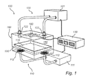
- a microwave heating apparatus 100 e.g. a microwave oven, having features and functions according to an embodiment of the present invention.
- the microwave oven 100 comprises a cavity 150 defined by an enclosing surface or external casing 160.
- the cavity 150 is arranged to receive a piece of food to be heated and, in particular, may be equipped with a bottom shelf 190 for receiving the piece of food or an accessory 170 containing the piece of food.
- the bottom shelf 190 may for instance be made of glass.
- the microwave oven further comprises a first microwave supply system 110, a second microwave supply system 120 and a control unit 130 configured to control the first and second microwave supply systems 110 and 120 based on a food category and/or a cooking program.
- the first supply system 110 comprises at least one microwave source 111 (or a generating block comprising a plurality of microwave sources) and at least one antenna 112 arranged in a lower part of the cavity, e.g. at the cavity bottom or at the bottom of the side walls of the cavity, for supplying microwaves under the bottom shelf 190.
- the first microwave supply system 110 is configured to supply microwaves at the cavity bottom for energizing a browning function in the cavity, i.e. such that a browning function is provided using a crisp or browning plate 170 arranged on the bottom shelf 190.
- the antennas are arranged such that a suitable electromagnetic field is provided between the bottom of the cavity 150 and the crisp or browning plate 170 for feeding the sole of the plate 170 with energy. More specifically, the antennas are configured such that the electric field vector is directed substantially perpendicular to the sole of the browning plate 170.
- the crisp or browning plate 170 usually comprises a microwave-absorbing layer arranged in thermal contact with another layer having relatively good thermal conductivity.
- the antennas are preferably arranged such that the magnetic field vector of microwaves fed into the cavity is directed substantially along the microwave-absorbing layer in order to generate magnetic losses in the layer and thereby heat the crisp or browning plate 170.
- the microwave-absorbing layer corresponds to the underside (or the sole) of the crisp or browning plate 170 and the piece of food can be browned on the thermally conductive layer, i.e. at the upper side of the browning plate 170.
- the upper side of the crisp or browning plate may consist of an aluminum (or steel) plate which has small thermal mass and good thermal conductivity and possibly a non-stick coating.
- no particular distinction is made between a crisp plate and a browning plate and reference to a crisp plate in the following could equally be made to a browning plate and vice versa.
- the underside of the crisp plate is provided with a microwave-absorbing layer which may be rubber-embedded ferrite (in a proportion of about 75% ferrite and 25% silicon dioxide).
- the ferrite material has a Curie point at which absorption of microwaves in the material ceases.
- the characteristics for absorption of the microwaves in the ferrite material may be varied by altering the thickness of the layer and/or the composition of the material.
- the temperature of the upper side of the crisp plate that comes into contact with the piece of food stabilizes in a temperature range of 130-230°C.
- the second microwave supply system 120 is configured to supply microwaves into the cavity 150 for exciting cavity modes.
- the second supply system 120 comprises at least one microwave source 121 and at least one feeding port 122 arranged in an upper part of the cavity 150.
- the feeding ports 122 may be arranged at, in principle, any of the walls of the cavity 150 such as a side wall or the ceiling. However, there is generally an optimized location of the feeding port for a predefined cavity mode structure. In the example shown in Figure 1 , two feeding ports 122 are used and both feeding ports are arranged at the ceiling of the cavity 150, thereby providing standard microwave heating by direct absorption of microwaves in the piece of food.
- the microwave oven 100 comprises a control unit 130 for controlling the first and second microwave supply systems 110 and 120.
- the control unit 130 acts as a shared control system for the first and second microwave supply systems 110 and 120 and is configured to control them based on a food category or cooking program.
- the control unit 130 may determine which of the microwave supply systems 110 and 120 is to be activated and according to which mode of operation.
- the determination of the operation mode by the control unit 130 may be realized by means of algorithms that optimize, or at least improve, the balance between different energy sources, for example the balance between microwave heating via the crisp function at the bottom of the cavity and standard microwave heating via the feeding ports at the ceiling of the cavity.
- a food category may correspond to a specific type of food, such as e.g. a pizza or French fries thereby defining, on the one hand, a type of food which is compact and may cover a relatively large area of the bottom shelf 190 and, on the other hand, a type of food which is dispersed in the form of elongated pieces.
- a food category may also comprise the state of the piece of food, e.g. frozen, thawed or liquid.
- a type of food category may therefore also be beverage.
- a cooking program may be at least one of defrosting, frying, grill, baking, roasting, standard heating and upper browning.
- the control unit 130 can determine an appropriate mode of operation for heating and control the first and second microwave supply systems 110 and 120 accordingly.
- the first and second microwave supply systems 110 and 120 may be controlled individually, thereby allowing that both or just one of them is activated depending on the type of cooking program or food category.
- control unit 130 may be configured to separately control the properties (such as frequency, phase and power) of the microwaves transmitted into the cavity 150 by either one of the first and second microwave supply systems 110 and 120.
- control unit 130 may also be connected to sensors, such as field sensors or temperature sensors, for monitoring the conditions in the cavity 150 and, then, control the microwave supply systems 110 and 120 based on the information provided by the sensors during the heating procedure.
- sensors such as field sensors or temperature sensors
- the oven may also be equipped with other heat sources, such as a grill element 180 or a heating source based on force convection (or convection and steam), for providing an additional source of heating and thereby increasing the cooking capability of the microwave heating apparatus 100.
- the grill element 180 may be arranged in the ceiling of the cavity 150.
- the grill element may for example be a so-called "grill tube", a quartz tube, a halogen-radiation source or an IR-radiating heater.
- the control unit 130 may therefore act as a shared control system for the first and second microwave supply systems 110 and 120 and for any additional heat source, such as the grill element 180.
- the control unit 130 may then be configured to control these various sources based on the food category or cooking program according to a mode of operation.
- the control unit 130 may in particular be configured to control the microwave generators 111 and 121 (e.g. their power) of the first and second microwave supply systems 110 and 120 and any power supply connected to the grill element 180.
- a microwave heating apparatus 200 e.g. a microwave oven, having features and functions according to another embodiment of the present invention.
- the microwave oven 200 comprises a cavity 250 defined by an enclosing surface or external casing 260.
- One of the side walls of the cavity 250 may be equipped with a door 255 for enabling the introduction of a load, e.g. a food item, in the cavity 250.
- the cavity 250 is also provided with two feeding ports 222 through which microwaves generated by the microwave source 221 (e.g. a magnetron or a solid-state microwave generator) of the second microwave supply system 220 can be fed.
- Each of the microwave feeding ports 222 of the cavity 250 is connected to the microwave source 221 of the second microwave supply system 220 by means of a transmission line 223.
- the transmission line 223 may be a waveguide, a coaxial cable or a strip line.
- regular waveguides may be used as transmission lines and the apertures may be of the same size as the waveguide cross-section.
- the microwave oven 200 may also comprise switches (not shown), each being associated with a feeding port 222 arranged in the transmission line 223 for stopping the feeding of a respective feeding port.
- the microwave oven 200 may also comprise a grill element 280 arranged at the ceiling of the cavity 250.
- the microwave oven 200 of Figure 2 comprises a first microwave supply system 210 for providing a browning function at the bottom of the cavity 250 (via a number of distributed antennas 212), a second microwave supply system 220 for excitation of cavity modes and a control unit 230 for controlling the first and second microwave supply systems 210 and 220.
- Figure 2 explicitly shows a user interface for selection of a food category or cooking program.
- the user interface may comprise a display or control panel 295 which may show symbols or plain-text messages for selection of a food category or cooking program and for verification of the selections.
- the display 295 may also show the remaining cooking or heating time during the cooking procedure, i.e. provide information on how the cooking or heating proceeds.
- the user interface may comprise at least one control button 290 or knob for entering information about the food category corresponding to the piece of food to be heated and/or information about a desired cooking program.
- the user interface may comprise a touch screen enabling both entry and display of information.
- the user interface may preferably be in communication with the control unit 230 such that the entered information can be processed by the control unit 230.
- the control unit 230 may then start a preprogrammed mode of operation in accordance with the entered information for implementing the desired cooking program.
- the microwave oven 200 comprises at least two microwave supply systems 210 and 220 connected to the control unit 230.
- the control unit 230 may be configured to regulate the respective power of the first microwave supply system 210, the second microwave supply system 220 and/or the grill element 280 on the basis of a cooking program or food category selected (or input) via the user interface.
- the control unit 230 may for instance use a look-up table for matching the entered information with parameters already stored in the look-up table and thereby retrieving an appropriate mode of operation for controlling the first and second microwave supply systems 210 and 220.
- the use of a look-up table is advantageous in that the microwave heating apparatus can itself retrieve the appropriate mode of operation (with details on, e.g., which types of heat source is to be activated, at which power level and for which period of time) based on information (facts) entered by a user via the user interface without the need of estimation by the user.
- the preprogrammed operation mode may include a sequential and/or simultaneous operation (or a combination of sequential and simultaneous operation) of the grill element, the standard microwave heating in the upper part of the cavity and the crisp function at the bottom of the cavity.
- a sequential and/or simultaneous operation or a combination of sequential and simultaneous operation
- the grill element is activated to provide the right color and melting of ingredients on top of the pizza
- the crisp function is activated for providing the right consistence of the food
- the standard microwave heating provides heating and preparation of the core of the deep-frozen pizza.
- control unit 230 may be configured to only activate the first microwave supply system 210 (for the underneath crisp function) and the top grill element 280 (for the grill function), thereby frying the piece of food arranged in the cavity.
- the user interface may therefore enable selection of various types of food category and cooking program such that a specific food category and cooking program can be retrieved in the look-up table, thereby activating the heat sources in accordance with a specific mode of operation.
- the microwave heating apparatus may also comprise a sensor (not shown) configured to detect if a browning plate is present in the cavity 250 or, alternatively, detect on which kind of plate the piece of food is placed.
- the control unit 230 may then be configured to activate the first microwave supply system 210 if a browning plate is detected.
- it may also be preferable to activate the first microwave supply system 210 even if no browning plate is detected.
- Figure 2 illustrates also that the first microwave supply system 210 may comprise a plurality of microwave sources and antennas 212 distributed at the bottom of the cavity, thereby improving uniformity of the crisp function and reducing the need of rotation of the crisp plate.
- the microwave source 211 of the first microwave supply system 210 is represented by a single generator block comprising four separate microwave sources, each of those being connected to a specific antenna.
- the antennas may be H-loop or patch antennas or any combination of such antennas.
- the microwave sources of the first and second microwave supply systems 110, 120, 210 and 220 may be solid-state based microwave generators.
- the advantages of a solid-state based microwave generator comprise the possibility of controlling the output power level of the generator and an inherent narrow-band feature.
- the frequencies of the microwaves that are emitted from a solid-state based generator usually constitute a narrow range of frequencies such as 2.4 to 2.5 GHz.
- the present invention is not limited to such a range of frequencies and the solid-state based microwave sources 111, 121, 211 and 221 could be adapted to emit in a range centered at 915 MHz, for instance 875-955 MHz, or any other suitable range of frequency (or bandwidth).
- the present invention is for instance applicable for standard sources having mid-band frequencies of 915 MHz, 2450 MHz, 5800 MHz and 22.125 GHz.
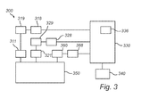
- FIG. 3 there is shown a block diagram illustrating the functional units of a microwave heating apparatus 300 in accordance with an embodiment of the present invention.
- the microwave heating apparatus 300 may be equivalent to any one of the microwave heating apparatuses 100 and 200 described above with reference to Figures 1 and 2 , respectively.
- FIG. 3 shows a control unit 330 (which may be the control units 130 or 230 described above with reference to Figures 1 and 2 , respectively) comprising a microprocessor and a program store 336 for storing a look-up table comprising preprogrammed operation modes and parameters such as described above with reference to Figure 2 .
- Information about food category and cooking program may be inputted via the user interface 340, which may correspond to a touch screen or the display 290 and the control buttons 295 and any optional knob described above with reference to Figure 2 .
- the control unit 330 can control the microwave source 311 of the first microwave supply system (which may be equivalent to the first microwave supply systems 110 or 210 described above with reference to Figures 1 and 2 , respectively) providing the crisp function.
- the control unit 330 can control the microwave source 321 of the second microwave supply system (which may be equivalent to the second microwave supply systems 120 or 220 described above with reference to Figures 1 and 2 , respectively) providing standard microwave heating by excitation of cavity modes.
- the control unit 330 can control the grill element 380 (which may be equivalent to any one of the grill elements 180 and 280 described above with reference to Figures 1 and 2 , respectively) providing the grill function or top browning.
- the grill element 380 may also be a browning element, i.e. an element operated at a relatively lower power and mainly configured for browning (i.e. giving an adequate color) to the piece of food.
- the control unit 330 may then control the various heat sources 311, 321 and 380 to optimize the heating or cooking of the piece of food introduced in the cavity in accordance with the food category and the desired cooking program.
- the control unit 330 may activate the heat sources according to a specific mode of operation, i.e. at adjusted power levels and for a suitable period of time during the cooking or heating procedure.
- the cavity of the microwave oven is not limited to such a shape and that it is also envisaged to implement the present invention in a cavity having a circular cross section or any other geometries describable in an orthogonal curve-linear coordinate system.
- the grill element has been described in the application to be arranged at the ceiling of the cavity, it will be appreciated that the grill element may in principle be arranged at any wall of the cavity.
- any number of antennas may be used such that a uniform crisp function at the bottom of the cavity is achieved or such that any shape of browning plates may be used without the need of rotation of the plate.
- the second microwave supply system comprises two feeding ports in the embodiments described with reference to Figures 1 and 2 , it will be appreciated that the second supply system may comprise a single feeding port or more than two feeding ports.
Landscapes
- Physics & Mathematics (AREA)
- Electromagnetism (AREA)
- Electric Ovens (AREA)
- Constitution Of High-Frequency Heating (AREA)
- Cookers (AREA)
Abstract
Description
- The present invention relates to the field of microwave heating and, in particular, to a versatile microwave heating apparatus.
- The art of microwave heating involves feeding of microwave energy into a cavity. Although the basic function of a microwave oven is to heat food by dielectric heating (i.e. via directly acting microwaves absorbed in the food), microwave ovens have been developed to include additional kinds of cooking capabilities, such as e.g. a crisp (or browning) function or a grill function, thereby enabling preparation of various types of food items and providing new culinary effects. Such additional kinds of cooking capabilities usually require additional components such as a browning plate or a grill element.
- An example of such a microwave oven is for instance described in American patent
US5595673 , wherein the microwave oven comprises a magnetron, a browning plate acting as a bottom heater (on which the food is placed) and optionally an IR-radiating top heater, which all can be controlled via a control unit of the oven. The microwave oven comprises also a feeding system with an upper opening for supplying the directly acting microwaves and a lower opening for supplying microwaves under the bottom heater. Both openings are arranged in the right-hand lateral wall of the cavity. - A drawback of such prior art microwave ovens is that, while the design of a microwave oven may be optimized (or improved) for a specific function (usually the directly acting microwaves, also referred to as standard microwave heating in the following), this is often made at the detriment of another function (typically the crisp function). The crisp function of prior art microwave ovens is therefore usually not optimized. In addition, as the crisp function is obtained via the feeding system used for standard microwave heating, the performance of the crisp function may also significantly vary from one type of microwave oven to another.
- Thus, there is a need for providing alternatives and/or new apparatuses that would overcome such drawbacks.
- An object of the present invention is to provide a more efficient alternative to the above technique and prior art.
- More specifically, it is an object of the present invention to provide a versatile microwave heating apparatus with an improved crisp function.
- This and other objects of the present invention are achieved by means of a microwave heating apparatus having the features defined in the independent claim. Preferable embodiments of the invention are characterized by the dependent claims.
- Hence, a microwave heating apparatus as defined in claim 1 is provided. The microwave heating apparatus comprises a cavity arranged to receive a piece of food to be heated, a first microwave supply system configured to supply microwaves at the cavity bottom for energizing a browning function in the cavity, a second microwave supply system configured to supply microwaves into the cavity for exciting cavity modes and a control unit configured to control the first and the second microwave supply systems based on a food category and/or a cooking program. The first microwave supply system comprises at least one microwave source and at least one antenna arranged in a lower port of the cavity and the second microwave supply system comprises at least one microwave source and at least one feeding port arranged in an upper part of the cavity.
- The present invention makes use of an understanding that, the crisp function being generally achieved based on the already existing system for standard microwave heating via directly acting microwaves (also referred to as volume heating in the following) in traditional microwave ovens, a compromise has to be made between optimization (or at least improvement) of the crisp function and optimization (or improvement) of the standard microwave heating. As microwave ovens are primarily used for standard microwave heating (i.e. volume heating by excitation of cavity modes), the effectiveness of the crisp function is often limited and rather poor. In the present invention, a separate microwave supply system configured to supply microwaves at the cavity bottom is provided for the browning function. With such a first microwave supply system including a microwave source and at least one antenna dedicated to the supply of microwaves at the bottom of the cavity, a microwave heating apparatus with an improved browning (or crisp) function is provided. Indeed, the present invention is advantageous in that a microwave heating apparatus for standard microwave heating by excitation of cavity modes and with a crisp function is provided without the need of any specific design tradeoff between the two types of heating such as in prior art microwave ovens. As a result, a microwave heating apparatus may be designed with an improved browning function without affecting the performance (e.g. uniformity or available power) of the standard microwave heating obtained by excitation of cavity modes.
- Further, the present invention is advantageous in that it provides a greater flexibility in cooking modes. Using separate microwave supply systems for the crisp function and the standard microwave heating, the control unit of the microwave heating apparatus can monitor which one of the two microwave supply systems needs to be used depending on a food category or cooking program. In other words, the present invention is advantageous in that the control unit can activate the microwave supply system that provides the most beneficial type of heating for the food.
- In addition, with the present invention, the microwave heating apparatus is not limited to use only a fraction of the available power if both standard microwave heating and the crisp function are desired but, instead, may use the full power of the first microwave supply system dedicated to the browning function and, still, via the second microwave supply system, provide some (or full) power for standard microwave heating.
- Further, the present invention is advantageous in that it reduces power consumption as a microwave supply system is configured and designed for a specific heating function. In comparison, traditional microwave ovens usually result in an excessive power consumption since the microwave generator and system initially designed and configured for standard microwave heating is also used for achieving the desired crisp function. Consequently, in prior art microwave ovens, more power than what is required is used for the crisp function.
- The present invention is also advantageous in that it does not require any complex feeding system or power divider.
- According to an embodiment, the microwave heating apparatus may further comprise a user interface for selection of a food category or cooking program. In particular, the food category may correspond to a specific type of food or state of food and the cooking program may include at least one of the group comprising defrosting, frying, grill, baking, roasting, standard heating and upper browning. Although it may be envisaged that the microwave heating apparatus comprises a number of sensors enabling recognition of the type of food inserted in the cavity and/or the state of the food for selecting a mode of operation, the present embodiment is advantageous in that a user may directly input such information in the microwave heating apparatus. The control unit may then process such information and thereafter select the appropriate mode of operation (i.e. which of the microwave supply systems is to be used and how) for the microwave heating apparatus.
- According to an embodiment, the microwave heating apparatus may further comprise a grill element (a resistive element or IR-radiating heater) arranged at a wall of the cavity for providing a grill function or top browning, which is advantageous in that it provides an additional source of heating and an additional degree of freedom in the mode of operation of the microwave heating apparatus. The resistive element or IR-radiating heater may e.g. be placed at the ceiling of the cavity, i.e. above the food, thereby acting as a top heater.
- According to an embodiment, the control unit may be configured to regulate the respective power of the first microwave supply system, the second microwave supply system and/or the grill element on the basis of a selected cooking program or food category. The present embodiment is advantageous in that the control unit may separately monitor the various heating sources and thereby optimize (or at least improve) the operation mode as a function of the selected cooking program or food category. In particular, the control unit may be configured to activate only the first microwave supply system for the crisp function and the grill element for the grill function if the cooking program is selected to be frying.
- According to another embodiment, the microwave heating apparatus may further comprise a sensor configured to detect if a browning plate arranged to receive a piece of food is introduced in the cavity. The present embodiment is advantageous in that the control unit may then monitor the first microwave supply system as a function of the information provided by the sensor. In particular, the control unit may be configured to activate the first microwave supply system if a browning plate is detected. However, some cooking programs or food items may require bottom heating (e.g. using a certain percentage of the total power available from the first microwave supply system) even if no browning plate is inserted in the cavity. Thus, the control unit is still configured to regulate the power of the first microwave supply system depending on the cooking program or food category but some additional information may also be provided by a sensor and used by the control unit for determining the mode of operation.
- According to yet another embodiment, the first microwave supply system may comprise at least two pairs of microwave source and antenna distributed at the bottom of the cavity. The present embodiment is advantageous in that a plurality of microwave sources and antennas distributed in the lower part of the cavity (e.g. at the cavity bottom) improves the uniformity and/or the total power of the crisp effect.
- According to an embodiment, the microwave source of either one of the first and second microwave supply systems may be at least one of a solid state microwave generator and a magnetron. The advantages of a solid-state microwave generator comprise the possibility of controlling the frequency of the generated microwaves, controlling the output power of the generator and an inherent narrow-band spectrum.
- Further, solid-state microwave generators are relatively more compact than magnetrons and, thus, are advantageous in domestic applications where a plurality of microwave sources needs to be used such as for implementing the first and second microwave supply systems and for improving the uniformity of the crisp function. However, for professional applications, wherein significantly larger apparatus than home appliances are used, it may be envisaged to use a plurality of magnetrons for improving uniformity of e.g. the crisp function. In addition, the uniform distribution of a plurality of solid-state microwave generators in the lower part of the cavity is advantageous in that rotation of the browning plate (which rotation usually is used for improving uniformity) is not required, thereby providing a larger freedom for designing the browning plate, which does not have to be circular. The arrangement of the plurality of solid state microwave generators in the lower part of the cavity (e.g. at the cavity bottom) may therefore allow for a rectangular browning plate or any other shape of browning plates.
- According to an embodiment, the microwave heating apparatus may comprise a feeding system (or at least a transmission line) for feeding the microwaves generated by the microwave source of the second supply system to the feeding port. It will be appreciated that the transmission line may be a standard one such as, e.g., a waveguide, a coaxial cable or a strip line.
- Further objectives of, features of, and advantages with, the present invention will become apparent when studying the following detailed disclosure, the drawings and the appended claims. Those skilled in the art realize that different features of the present invention can be combined to create embodiments other than those described in the following.
- The above, as well as additional objects, features and advantages of the present invention, will be better understood through the following illustrative and non-limiting detailed description of preferred embodiments of the present invention, with reference to the appended drawings, in which:
-
Figure 1 schematically shows a microwave heating apparatus according to an exemplifying embodiment of the present invention; -
Figure 2 schematically shows a microwave heating apparatus according to another exemplifying embodiment of the present invention; and -
Figure 3 shows a block diagram illustrating the functional units of a microwave heating apparatus according to an exemplifying embodiment of the present invention. - All the figures are schematic, not necessarily to scale, and generally only show parts which are necessary in order to elucidate the invention, wherein other parts may be omitted or merely suggested.
- With reference to
Figure 1 , there is shown amicrowave heating apparatus 100, e.g. a microwave oven, having features and functions according to an embodiment of the present invention. - The
microwave oven 100 comprises acavity 150 defined by an enclosing surface orexternal casing 160. Thecavity 150 is arranged to receive a piece of food to be heated and, in particular, may be equipped with abottom shelf 190 for receiving the piece of food or anaccessory 170 containing the piece of food. Thebottom shelf 190 may for instance be made of glass. - The microwave oven further comprises a first
microwave supply system 110, a secondmicrowave supply system 120 and acontrol unit 130 configured to control the first and secondmicrowave supply systems - The
first supply system 110 comprises at least one microwave source 111 (or a generating block comprising a plurality of microwave sources) and at least oneantenna 112 arranged in a lower part of the cavity, e.g. at the cavity bottom or at the bottom of the side walls of the cavity, for supplying microwaves under thebottom shelf 190. The firstmicrowave supply system 110 is configured to supply microwaves at the cavity bottom for energizing a browning function in the cavity, i.e. such that a browning function is provided using a crisp orbrowning plate 170 arranged on thebottom shelf 190. Advantageously, the antennas are arranged such that a suitable electromagnetic field is provided between the bottom of thecavity 150 and the crisp orbrowning plate 170 for feeding the sole of theplate 170 with energy. More specifically, the antennas are configured such that the electric field vector is directed substantially perpendicular to the sole of thebrowning plate 170. - The crisp or
browning plate 170 usually comprises a microwave-absorbing layer arranged in thermal contact with another layer having relatively good thermal conductivity. In particular, the antennas are preferably arranged such that the magnetic field vector of microwaves fed into the cavity is directed substantially along the microwave-absorbing layer in order to generate magnetic losses in the layer and thereby heat the crisp orbrowning plate 170. The microwave-absorbing layer corresponds to the underside (or the sole) of the crisp orbrowning plate 170 and the piece of food can be browned on the thermally conductive layer, i.e. at the upper side of thebrowning plate 170. Generally, the upper side of the crisp or browning plate may consist of an aluminum (or steel) plate which has small thermal mass and good thermal conductivity and possibly a non-stick coating. In the present specification, no particular distinction is made between a crisp plate and a browning plate and reference to a crisp plate in the following could equally be made to a browning plate and vice versa. - The underside of the crisp plate is provided with a microwave-absorbing layer which may be rubber-embedded ferrite (in a proportion of about 75% ferrite and 25% silicon dioxide). The ferrite material has a Curie point at which absorption of microwaves in the material ceases. The characteristics for absorption of the microwaves in the ferrite material may be varied by altering the thickness of the layer and/or the composition of the material. Generally, the temperature of the upper side of the crisp plate that comes into contact with the piece of food stabilizes in a temperature range of 130-230°C.
- The second
microwave supply system 120 is configured to supply microwaves into thecavity 150 for exciting cavity modes. Thesecond supply system 120 comprises at least onemicrowave source 121 and at least one feedingport 122 arranged in an upper part of thecavity 150. The feedingports 122 may be arranged at, in principle, any of the walls of thecavity 150 such as a side wall or the ceiling. However, there is generally an optimized location of the feeding port for a predefined cavity mode structure. In the example shown inFigure 1 , two feedingports 122 are used and both feeding ports are arranged at the ceiling of thecavity 150, thereby providing standard microwave heating by direct absorption of microwaves in the piece of food. - Further, the
microwave oven 100 comprises acontrol unit 130 for controlling the first and secondmicrowave supply systems control unit 130 acts as a shared control system for the first and secondmicrowave supply systems control unit 130 may determine which of themicrowave supply systems control unit 130 may be realized by means of algorithms that optimize, or at least improve, the balance between different energy sources, for example the balance between microwave heating via the crisp function at the bottom of the cavity and standard microwave heating via the feeding ports at the ceiling of the cavity. - According to an embodiment, a food category may correspond to a specific type of food, such as e.g. a pizza or French fries thereby defining, on the one hand, a type of food which is compact and may cover a relatively large area of the
bottom shelf 190 and, on the other hand, a type of food which is dispersed in the form of elongated pieces. Further, a food category may also comprise the state of the piece of food, e.g. frozen, thawed or liquid. A type of food category may therefore also be beverage. - According to an embodiment, a cooking program may be at least one of defrosting, frying, grill, baking, roasting, standard heating and upper browning. Depending on the cooking program and/or food category, the
control unit 130 can determine an appropriate mode of operation for heating and control the first and secondmicrowave supply systems - The first and second
microwave supply systems - Further, the
control unit 130 may be configured to separately control the properties (such as frequency, phase and power) of the microwaves transmitted into thecavity 150 by either one of the first and secondmicrowave supply systems - Optionally, the
control unit 130 may also be connected to sensors, such as field sensors or temperature sensors, for monitoring the conditions in thecavity 150 and, then, control themicrowave supply systems - According to an embodiment, the oven may also be equipped with other heat sources, such as a
grill element 180 or a heating source based on force convection (or convection and steam), for providing an additional source of heating and thereby increasing the cooking capability of themicrowave heating apparatus 100. Advantageously, thegrill element 180 may be arranged in the ceiling of thecavity 150. The grill element may for example be a so-called "grill tube", a quartz tube, a halogen-radiation source or an IR-radiating heater. - The
control unit 130 may therefore act as a shared control system for the first and secondmicrowave supply systems grill element 180. Thecontrol unit 130 may then be configured to control these various sources based on the food category or cooking program according to a mode of operation. - The
control unit 130 may in particular be configured to control themicrowave generators 111 and 121 (e.g. their power) of the first and secondmicrowave supply systems grill element 180. With reference toFigure 2 , there is shown amicrowave heating apparatus 200, e.g. a microwave oven, having features and functions according to another embodiment of the present invention. - The
microwave oven 200 comprises acavity 250 defined by an enclosing surface orexternal casing 260. One of the side walls of thecavity 250 may be equipped with adoor 255 for enabling the introduction of a load, e.g. a food item, in thecavity 250. - In the
microwave oven 200, thecavity 250 is also provided with two feedingports 222 through which microwaves generated by the microwave source 221 (e.g. a magnetron or a solid-state microwave generator) of the secondmicrowave supply system 220 can be fed. Each of themicrowave feeding ports 222 of thecavity 250 is connected to themicrowave source 221 of the secondmicrowave supply system 220 by means of atransmission line 223. Thetransmission line 223 may be a waveguide, a coaxial cable or a strip line. In the example shown inFigure 2 , regular waveguides may be used as transmission lines and the apertures may be of the same size as the waveguide cross-section. However, this is not necessarily the case and a multitude of other arrangements can be used such as, e.g., E-probes, H-loops, helices, patch antennas and resonant high-ε bodies arranged at the junction between thetransmission line 223 and thecavity 250. Optionally, themicrowave oven 200 may also comprise switches (not shown), each being associated with a feedingport 222 arranged in thetransmission line 223 for stopping the feeding of a respective feeding port. - Optionally, the
microwave oven 200 may also comprise agrill element 280 arranged at the ceiling of thecavity 250. - The main features and functions of the
microwave oven 200 ofFigure 2 are identical to the main features and functions of themicrowave oven 100 described with reference toFigure 1 . In particular, themicrowave oven 200 comprises a firstmicrowave supply system 210 for providing a browning function at the bottom of the cavity 250 (via a number of distributed antennas 212), a secondmicrowave supply system 220 for excitation of cavity modes and acontrol unit 230 for controlling the first and secondmicrowave supply systems Figure 2 explicitly shows a user interface for selection of a food category or cooking program. - In particular, the user interface may comprise a display or
control panel 295 which may show symbols or plain-text messages for selection of a food category or cooking program and for verification of the selections. Optionally, thedisplay 295 may also show the remaining cooking or heating time during the cooking procedure, i.e. provide information on how the cooking or heating proceeds. - Further, the user interface may comprise at least one
control button 290 or knob for entering information about the food category corresponding to the piece of food to be heated and/or information about a desired cooking program. - Alternatively, the user interface may comprise a touch screen enabling both entry and display of information.
- The user interface may preferably be in communication with the
control unit 230 such that the entered information can be processed by thecontrol unit 230. Thecontrol unit 230 may then start a preprogrammed mode of operation in accordance with the entered information for implementing the desired cooking program. - The
microwave oven 200 comprises at least twomicrowave supply systems control unit 230. In particular, thecontrol unit 230 may be configured to regulate the respective power of the firstmicrowave supply system 210, the secondmicrowave supply system 220 and/or thegrill element 280 on the basis of a cooking program or food category selected (or input) via the user interface. Based on the entered information, thecontrol unit 230 may for instance use a look-up table for matching the entered information with parameters already stored in the look-up table and thereby retrieving an appropriate mode of operation for controlling the first and secondmicrowave supply systems - For example, if the information entered by the user (i.e. the selected food category) corresponds to a deep-frozen pizza, the preprogrammed operation mode may include a sequential and/or simultaneous operation (or a combination of sequential and simultaneous operation) of the grill element, the standard microwave heating in the upper part of the cavity and the crisp function at the bottom of the cavity. Each of these three types of heat sources will provide a specific culinary effect which will result in an efficient and appropriate preparation of the deep-frozen pizza. In this specific example, the grill element is activated to provide the right color and melting of ingredients on top of the pizza, the crisp function is activated for providing the right consistence of the food and the standard microwave heating provides heating and preparation of the core of the deep-frozen pizza.
- In another example, if the pizza was not deep-frozen but already prepared and stored in a fridge, activation of the grill element and the crisp function would be sufficient for warming up the pizza.
- In another example, if the cooking program is selected to be "frying", the
control unit 230 may be configured to only activate the first microwave supply system 210 (for the underneath crisp function) and the top grill element 280 (for the grill function), thereby frying the piece of food arranged in the cavity. - The user interface may therefore enable selection of various types of food category and cooking program such that a specific food category and cooking program can be retrieved in the look-up table, thereby activating the heat sources in accordance with a specific mode of operation.
- Optionally, the microwave heating apparatus may also comprise a sensor (not shown) configured to detect if a browning plate is present in the
cavity 250 or, alternatively, detect on which kind of plate the piece of food is placed. Thecontrol unit 230 may then be configured to activate the firstmicrowave supply system 210 if a browning plate is detected. However, depending on the desired cooking program and/or food category, it may also be preferable to activate the firstmicrowave supply system 210 even if no browning plate is detected. -
Figure 2 illustrates also that the firstmicrowave supply system 210 may comprise a plurality of microwave sources andantennas 212 distributed at the bottom of the cavity, thereby improving uniformity of the crisp function and reducing the need of rotation of the crisp plate. InFigure 2 , themicrowave source 211 of the firstmicrowave supply system 210 is represented by a single generator block comprising four separate microwave sources, each of those being connected to a specific antenna. The antennas may be H-loop or patch antennas or any combination of such antennas. - According to an embodiment, the microwave sources of the first and second
microwave supply systems microwave sources - With reference to
Figure 3 , there is shown a block diagram illustrating the functional units of amicrowave heating apparatus 300 in accordance with an embodiment of the present invention. - The
microwave heating apparatus 300 may be equivalent to any one of themicrowave heating apparatuses Figures 1 and2 , respectively. - The block diagram of
Figure 3 shows a control unit 330 (which may be thecontrol units Figures 1 and2 , respectively) comprising a microprocessor and aprogram store 336 for storing a look-up table comprising preprogrammed operation modes and parameters such as described above with reference toFigure 2 . Information about food category and cooking program may be inputted via theuser interface 340, which may correspond to a touch screen or thedisplay 290 and thecontrol buttons 295 and any optional knob described above with reference toFigure 2 . Via adriver 318 and amicrowave power unit 319, thecontrol unit 330 can control themicrowave source 311 of the first microwave supply system (which may be equivalent to the firstmicrowave supply systems Figures 1 and2 , respectively) providing the crisp function. Similarly, via adriver 328 and amicrowave power unit 329, thecontrol unit 330 can control the microwave source 321 of the second microwave supply system (which may be equivalent to the secondmicrowave supply systems Figures 1 and2 , respectively) providing standard microwave heating by excitation of cavity modes. Further, via adriver 388 , thecontrol unit 330 can control the grill element 380 (which may be equivalent to any one of thegrill elements Figures 1 and2 , respectively) providing the grill function or top browning. Thegrill element 380 may also be a browning element, i.e. an element operated at a relatively lower power and mainly configured for browning (i.e. giving an adequate color) to the piece of food. - The
control unit 330 may then control thevarious heat sources control unit 330 may activate the heat sources according to a specific mode of operation, i.e. at adjusted power levels and for a suitable period of time during the cooking or heating procedure. - While specific embodiments have been described, the skilled person will understand that various modifications and alterations are conceivable within the scope as defined in the appended claims.
- For example, although a cavity having a rectangular cross-section has been described in the application, it will be appreciated that the cavity of the microwave oven is not limited to such a shape and that it is also envisaged to implement the present invention in a cavity having a circular cross section or any other geometries describable in an orthogonal curve-linear coordinate system.
- Further, although the grill element has been described in the application to be arranged at the ceiling of the cavity, it will be appreciated that the grill element may in principle be arranged at any wall of the cavity.
- Further, although four antennas connected to four microwave sources, respectively, are shown in
Figure 2 for implementing the first microwave supply system, any number of antennas may be used such that a uniform crisp function at the bottom of the cavity is achieved or such that any shape of browning plates may be used without the need of rotation of the plate. - Further, although the second microwave supply system comprises two feeding ports in the embodiments described with reference to
Figures 1 and2 , it will be appreciated that the second supply system may comprise a single feeding port or more than two feeding ports.
Claims (11)
- A microwave heating apparatus (100) comprising:a cavity (150) arranged to receive a piece of food to be heated;a first microwave supply system (110) configured to supply microwaves at the cavity bottom for energizing a browning function in the cavity, wherein the first microwave supply system comprises at least one microwave source (111) and at least one antenna (112) arranged in a lower part of the cavity;a second microwave supply system (120) configured to supply microwaves into the cavity for exciting cavity modes, wherein the second microwave supply system comprises at least one microwave source (121) and at least one feeding port (122) arranged in an upper part of the cavity; anda control unit (130) configured to control said first and second microwave supply systems based on a food category and/or a cooking program.
- The microwave heating apparatus of claim 1, further comprising a user interface (290, 295, 340) for selection of the food category or cooking program.
- The microwave heating apparatus of claim 1 or 2, wherein a food category corresponds to a specific type of food or state of food and wherein a cooking program includes at least one of the group comprising defrosting, frying, grill, baking, roasting, volume heating and upper browning.
- The microwave heating apparatus of any one of the preceding claims, wherein the microwave source of either one of the first and second supply systems is at least one of a solid state microwave generator and a magnetron.
- The microwave heating apparatus of any one of the preceding claims, further comprising a grill element (180) arranged at a wall of the cavity for providing a grill function or top browning.
- The microwave heating apparatus of any one of the preceding claims, wherein the control unit is configured to regulate the respective power of the first microwave supply system, the second microwave supply system and/or the grill element on the basis of a selected cooking program or food category.
- The microwave heating apparatus of claim 6, wherein the control unit is configured to activate only the first microwave supply system and the grill element if the cooking program is selected to be frying.
- The microwave heating apparatus of any one of the preceding claims, further comprising a sensor configured to detect if a browning plate (170) arranged to receive a piece of food is introduced in the cavity.
- The microwave heating apparatus of claim 8, wherein the control unit is configured to activate the first microwave supply system if a browning plate is detected.
- The microwave heating apparatus of any one of the preceding claims, wherein said first microwave supply system comprises at least two pairs of microwave source and antenna distributed at the bottom of the cavity.
- The microwave heating apparatus of any one of the preceding claims, further comprising at least one transmission line for feeding the microwaves generated by the microwave source of the second microwave supply system to the feeding port.
Priority Applications (4)
| Application Number | Priority Date | Filing Date | Title |
|---|---|---|---|
| EP10164960.6A EP2393339B1 (en) | 2010-06-04 | 2010-06-04 | Versatile microwave heating apparatus |
| PL10164960T PL2393339T3 (en) | 2010-06-04 | 2010-06-04 | Versatile microwave heating apparatus |
| US13/150,335 US9332597B2 (en) | 2010-06-04 | 2011-06-01 | Versatile microwave heating apparatus |
| US15/139,629 US9769884B2 (en) | 2010-06-04 | 2016-04-27 | Versatile microwave heating apparatus |
Applications Claiming Priority (1)
| Application Number | Priority Date | Filing Date | Title |
|---|---|---|---|
| EP10164960.6A EP2393339B1 (en) | 2010-06-04 | 2010-06-04 | Versatile microwave heating apparatus |
Publications (2)
| Publication Number | Publication Date |
|---|---|
| EP2393339A1 true EP2393339A1 (en) | 2011-12-07 |
| EP2393339B1 EP2393339B1 (en) | 2016-12-07 |
Family
ID=42802693
Family Applications (1)
| Application Number | Title | Priority Date | Filing Date |
|---|---|---|---|
| EP10164960.6A Not-in-force EP2393339B1 (en) | 2010-06-04 | 2010-06-04 | Versatile microwave heating apparatus |
Country Status (3)
| Country | Link |
|---|---|
| US (2) | US9332597B2 (en) |
| EP (1) | EP2393339B1 (en) |
| PL (1) | PL2393339T3 (en) |
Cited By (5)
| Publication number | Priority date | Publication date | Assignee | Title |
|---|---|---|---|---|
| EP2605617A1 (en) * | 2011-12-16 | 2013-06-19 | Whirlpool Corporation | Microwave heating apparatus with dual level cavity |
| CN108430127A (en) * | 2017-02-15 | 2018-08-21 | 合默麟机械股份有限公司 | Modular composite microwave heating system with separable cavity |
| CN109352894A (en) * | 2018-11-02 | 2019-02-19 | 郑州峰泰纳米材料有限公司 | A kind of continuous uniformity foam device of melamine bubble |
| EP3451794A1 (en) * | 2017-09-01 | 2019-03-06 | Whirlpool Corporation | Crispness and browning in full flat microwave oven |
| CN113540827A (en) * | 2021-07-16 | 2021-10-22 | 中国工程物理研究院应用电子学研究所 | An omnidirectional radiation high-power microwave system |
Families Citing this family (29)
| Publication number | Priority date | Publication date | Assignee | Title |
|---|---|---|---|---|
| US10225893B2 (en) | 2013-03-15 | 2019-03-05 | Tf Cardinal Llc | Cooking apparatus |
| US11191133B2 (en) | 2014-09-17 | 2021-11-30 | Whirlpool Corporation | Direct heating through patch antennas |
| EP3266281B1 (en) | 2015-03-06 | 2021-04-21 | Whirlpool Corporation | Method of calibrating a high power amplifier for a radio frequency power measurement system |
| US10251223B2 (en) * | 2015-05-20 | 2019-04-02 | Illinois Tool Works Inc. | Apparatus for providing customizable heat zones in an oven |
| EP3305019B1 (en) | 2015-06-03 | 2023-07-19 | Whirlpool Corporation | Method and device for electromagnetic cooking |
| US10764970B2 (en) | 2016-01-08 | 2020-09-01 | Whirlpool Corporation | Multiple cavity microwave oven insulated divider |
| EP3400755A1 (en) | 2016-01-08 | 2018-11-14 | Whirlpool Corporation | Method and apparatus for determining heating strategies |
| JP6775023B2 (en) | 2016-01-28 | 2020-10-28 | パナソニック株式会社 | Methods and equipment for transmitting high frequency electromagnetic energy to cook food |
| EP3417675B1 (en) | 2016-02-15 | 2020-03-18 | Whirlpool Corporation | Method and apparatus for delivering radio frequency electromagnetic energy to cook foodstuff |
| FR3050915B1 (en) * | 2016-05-03 | 2018-10-05 | Seb Sa | COOKING APPARATUS AND METHOD OF USING THE COOKING APPARATUS |
| CN109417839B (en) * | 2016-06-28 | 2021-10-12 | 惠而浦有限公司 | Multi-feed microwave oven with improved crisping |
| CN106211406B (en) * | 2016-07-13 | 2019-07-02 | 广东美的厨房电器制造有限公司 | Semiconductor microwave heating device |
| CN109644526A (en) * | 2016-09-15 | 2019-04-16 | 惠而浦有限公司 | Microwave oven oven with efficient honeycomb pattern grid |
| CA3033452A1 (en) * | 2016-10-28 | 2018-05-03 | Nestec S.A. | Method for cooking food in a solid state microwave oven |
| WO2018118065A1 (en) * | 2016-12-22 | 2018-06-28 | Whirlpool Corporation | Method and device for electromagnetic cooking using non-centered loads |
| US11039510B2 (en) | 2017-09-27 | 2021-06-15 | Whirlpool Corporation | Method and device for electromagnetic cooking using asynchronous sensing strategy for resonant modes real-time tracking |
| EP3637957A4 (en) | 2018-01-31 | 2020-11-18 | Guangdong Midea Kitchen Appliances Manufacturing Co., Ltd. | MICROWAVE COOKING DEVICE, CONTROL PROCEDURE AND STORAGE MEDIUM |
| US10772165B2 (en) | 2018-03-02 | 2020-09-08 | Whirlpool Corporation | System and method for zone cooking according to spectromodal theory in an electromagnetic cooking device |
| US11404758B2 (en) | 2018-05-04 | 2022-08-02 | Whirlpool Corporation | In line e-probe waveguide transition |
| US10912160B2 (en) | 2018-07-19 | 2021-02-02 | Whirlpool Corporation | Cooking appliance |
| CN112997583B (en) * | 2018-09-17 | 2025-01-07 | 可口可乐公司 | Packaged food product microwave system and method |
| US12396074B2 (en) * | 2018-11-15 | 2025-08-19 | Whirlpool Corporation | Hybrid nanoreinforced liner for microwave oven |
| US11234298B2 (en) * | 2018-11-15 | 2022-01-25 | Whirlpool Corporation | Hybrid nanoreinforced liner for microwave oven |
| US11632828B2 (en) * | 2019-08-13 | 2023-04-18 | Haier Us Appliance Solutions, Inc. | Cooking appliance operable in a crisp reheat cycle |
| KR102805215B1 (en) * | 2020-01-17 | 2025-05-12 | 삼성전자주식회사 | Cooking apparatus |
| KR20210136717A (en) * | 2020-05-08 | 2021-11-17 | 엘지전자 주식회사 | Oven includes a plurality of antennas and method of control the same |
| JP7680015B2 (en) * | 2021-04-22 | 2025-05-20 | 株式会社 クリスタル電器 | Semiconductor Oscillation Microwave Oven |
| CN113720103A (en) * | 2021-07-02 | 2021-11-30 | 广西科学院 | Drying process for different-frequency microwave synergistic heating of curcuma longa slices |
| US20230276981A1 (en) * | 2022-03-03 | 2023-09-07 | Whirlpool Corporation | Cooking vessel |
Citations (8)
| Publication number | Priority date | Publication date | Assignee | Title |
|---|---|---|---|---|
| US4427867A (en) * | 1982-12-03 | 1984-01-24 | General Electric Company | Power divider for microwave oven |
| US4499356A (en) * | 1982-04-07 | 1985-02-12 | Matsushita Electric Industrial Co., Ltd. | Microwave heater having a device for thawing frozen cakes |
| JPS60235388A (en) * | 1984-05-08 | 1985-11-22 | 松下電器産業株式会社 | High frequency heating device |
| EP0478082A1 (en) * | 1990-09-28 | 1992-04-01 | Whirlpool Europe B.V. | Microwave oven with browning means |
| JPH06193884A (en) * | 1992-12-21 | 1994-07-15 | Matsushita Electric Ind Co Ltd | High frequency heating cooker |
| GB2284133A (en) * | 1993-11-15 | 1995-05-24 | Toshiba Kk | High-frequency heater and method of controlling same |
| US5451751A (en) * | 1992-01-23 | 1995-09-19 | Kabushiki Kaisha Toshiba | High-frequency heating apparatus with wave guide switching means and selective power switching means for magnetron |
| US5595673A (en) | 1994-06-13 | 1997-01-21 | Whirlpool Europe B.V. | Microwave oven with microwave-actuable bottom and temperature sensor |
Family Cites Families (6)
| Publication number | Priority date | Publication date | Assignee | Title |
|---|---|---|---|---|
| SE458493B (en) * | 1987-01-08 | 1989-04-03 | Philips Norden Ab | MIKROVAAGSUGN |
| US5179264A (en) * | 1989-12-13 | 1993-01-12 | International Business Machines Corporation | Solid state microwave powered material and plasma processing systems |
| US5236614A (en) | 1990-09-25 | 1993-08-17 | Colgate-Palmolive Company | Stable microemulsion disinfecting detergent composition |
| US5204503A (en) * | 1991-12-17 | 1993-04-20 | Raytheon Company | Microwave oven having convection and griddle features |
| US5272302A (en) * | 1991-12-17 | 1993-12-21 | Raytheon Company | Microwave oven with improved cooking uniformity |
| US5523549A (en) * | 1994-05-25 | 1996-06-04 | Ceramic Powders, Inc. | Ferrite compositions for use in a microwave oven |
-
2010
- 2010-06-04 PL PL10164960T patent/PL2393339T3/en unknown
- 2010-06-04 EP EP10164960.6A patent/EP2393339B1/en not_active Not-in-force
-
2011
- 2011-06-01 US US13/150,335 patent/US9332597B2/en active Active
-
2016
- 2016-04-27 US US15/139,629 patent/US9769884B2/en active Active
Patent Citations (8)
| Publication number | Priority date | Publication date | Assignee | Title |
|---|---|---|---|---|
| US4499356A (en) * | 1982-04-07 | 1985-02-12 | Matsushita Electric Industrial Co., Ltd. | Microwave heater having a device for thawing frozen cakes |
| US4427867A (en) * | 1982-12-03 | 1984-01-24 | General Electric Company | Power divider for microwave oven |
| JPS60235388A (en) * | 1984-05-08 | 1985-11-22 | 松下電器産業株式会社 | High frequency heating device |
| EP0478082A1 (en) * | 1990-09-28 | 1992-04-01 | Whirlpool Europe B.V. | Microwave oven with browning means |
| US5451751A (en) * | 1992-01-23 | 1995-09-19 | Kabushiki Kaisha Toshiba | High-frequency heating apparatus with wave guide switching means and selective power switching means for magnetron |
| JPH06193884A (en) * | 1992-12-21 | 1994-07-15 | Matsushita Electric Ind Co Ltd | High frequency heating cooker |
| GB2284133A (en) * | 1993-11-15 | 1995-05-24 | Toshiba Kk | High-frequency heater and method of controlling same |
| US5595673A (en) | 1994-06-13 | 1997-01-21 | Whirlpool Europe B.V. | Microwave oven with microwave-actuable bottom and temperature sensor |
Cited By (7)
| Publication number | Priority date | Publication date | Assignee | Title |
|---|---|---|---|---|
| EP2605617A1 (en) * | 2011-12-16 | 2013-06-19 | Whirlpool Corporation | Microwave heating apparatus with dual level cavity |
| CN108430127A (en) * | 2017-02-15 | 2018-08-21 | 合默麟机械股份有限公司 | Modular composite microwave heating system with separable cavity |
| CN108430127B (en) * | 2017-02-15 | 2020-10-30 | 合默麟机械股份有限公司 | Modular composite microwave heating system with separable cavity |
| EP3451794A1 (en) * | 2017-09-01 | 2019-03-06 | Whirlpool Corporation | Crispness and browning in full flat microwave oven |
| US20190075624A1 (en) * | 2017-09-01 | 2019-03-07 | Whirlpool Corporation | Crispness and browning in full flat microwave oven |
| CN109352894A (en) * | 2018-11-02 | 2019-02-19 | 郑州峰泰纳米材料有限公司 | A kind of continuous uniformity foam device of melamine bubble |
| CN113540827A (en) * | 2021-07-16 | 2021-10-22 | 中国工程物理研究院应用电子学研究所 | An omnidirectional radiation high-power microwave system |
Also Published As
| Publication number | Publication date |
|---|---|
| EP2393339B1 (en) | 2016-12-07 |
| US9769884B2 (en) | 2017-09-19 |
| PL2393339T3 (en) | 2017-03-31 |
| US9332597B2 (en) | 2016-05-03 |
| US20160242241A1 (en) | 2016-08-18 |
| US20110297672A1 (en) | 2011-12-08 |
Similar Documents
| Publication | Publication Date | Title |
|---|---|---|
| EP2393339B1 (en) | Versatile microwave heating apparatus | |
| US12058798B2 (en) | Cooking apparatus and control method thereof | |
| US11395380B2 (en) | Method of heating a load in a cavity using microwaves | |
| US7355150B2 (en) | Food preparation system with inductive power | |
| JP5310741B2 (en) | Microwave heating cooker | |
| EP2605617B1 (en) | Microwave heating apparatus with dual level cavity | |
| CA2459604C (en) | Methods and apparatus for operating a speedcooking oven | |
| US11953261B2 (en) | Food treatment device | |
| JP2009144970A5 (en) | ||
| EP3298861B1 (en) | Apparatus for providing customizable heat zones in an oven | |
| EP2037784B1 (en) | A device and method for heating multiple prepared meals | |
| EP4368075A1 (en) | Recipe presentation method, cooking device, recipe presentation program, and recipe presentation system | |
| EP3476183B1 (en) | Multi-feed microwave oven with improved crisp function | |
| JP5496165B2 (en) | Cooker | |
| US10827569B2 (en) | Crispness and browning in full flat microwave oven | |
| JP2013153943A (en) | Tray for high frequency heating and high frequency heating apparatus | |
| KR200342080Y1 (en) | Steamed cooking vessel of a humidified type in a a microwave oven | |
| KR19990004980U (en) | microwave |
Legal Events
| Date | Code | Title | Description |
|---|---|---|---|
| AK | Designated contracting states |
Kind code of ref document: A1 Designated state(s): AL AT BE BG CH CY CZ DE DK EE ES FI FR GB GR HR HU IE IS IT LI LT LU LV MC MK MT NL NO PL PT RO SE SI SK SM TR |
|
| AX | Request for extension of the european patent |
Extension state: BA ME RS |
|
| PUAI | Public reference made under article 153(3) epc to a published international application that has entered the european phase |
Free format text: ORIGINAL CODE: 0009012 |
|
| 17P | Request for examination filed |
Effective date: 20120528 |
|
| 17Q | First examination report despatched |
Effective date: 20150622 |
|
| GRAP | Despatch of communication of intention to grant a patent |
Free format text: ORIGINAL CODE: EPIDOSNIGR1 |
|
| GRAS | Grant fee paid |
Free format text: ORIGINAL CODE: EPIDOSNIGR3 |
|
| INTG | Intention to grant announced |
Effective date: 20161005 |
|
| GRAA | (expected) grant |
Free format text: ORIGINAL CODE: 0009210 |
|
| STAA | Information on the status of an ep patent application or granted ep patent |
Free format text: STATUS: THE PATENT HAS BEEN GRANTED |
|
| AK | Designated contracting states |
Kind code of ref document: B1 Designated state(s): AL AT BE BG CH CY CZ DE DK EE ES FI FR GB GR HR HU IE IS IT LI LT LU LV MC MK MT NL NO PL PT RO SE SI SK SM TR |
|
| REG | Reference to a national code |
Ref country code: GB Ref legal event code: FG4D |
|
| REG | Reference to a national code |
Ref country code: CH Ref legal event code: EP Ref country code: AT Ref legal event code: REF Ref document number: 852690 Country of ref document: AT Kind code of ref document: T Effective date: 20161215 |
|
| REG | Reference to a national code |
Ref country code: IE Ref legal event code: FG4D |
|
| REG | Reference to a national code |
Ref country code: DE Ref legal event code: R096 Ref document number: 602010038570 Country of ref document: DE |
|
| PG25 | Lapsed in a contracting state [announced via postgrant information from national office to epo] |
Ref country code: LV Free format text: LAPSE BECAUSE OF FAILURE TO SUBMIT A TRANSLATION OF THE DESCRIPTION OR TO PAY THE FEE WITHIN THE PRESCRIBED TIME-LIMIT Effective date: 20161207 |
|
| REG | Reference to a national code |
Ref country code: LT Ref legal event code: MG4D |
|
| REG | Reference to a national code |
Ref country code: NL Ref legal event code: MP Effective date: 20161207 |
|
| PG25 | Lapsed in a contracting state [announced via postgrant information from national office to epo] |
Ref country code: NO Free format text: LAPSE BECAUSE OF FAILURE TO SUBMIT A TRANSLATION OF THE DESCRIPTION OR TO PAY THE FEE WITHIN THE PRESCRIBED TIME-LIMIT Effective date: 20170307 Ref country code: GR Free format text: LAPSE BECAUSE OF FAILURE TO SUBMIT A TRANSLATION OF THE DESCRIPTION OR TO PAY THE FEE WITHIN THE PRESCRIBED TIME-LIMIT Effective date: 20170308 Ref country code: SE Free format text: LAPSE BECAUSE OF FAILURE TO SUBMIT A TRANSLATION OF THE DESCRIPTION OR TO PAY THE FEE WITHIN THE PRESCRIBED TIME-LIMIT Effective date: 20161207 Ref country code: LT Free format text: LAPSE BECAUSE OF FAILURE TO SUBMIT A TRANSLATION OF THE DESCRIPTION OR TO PAY THE FEE WITHIN THE PRESCRIBED TIME-LIMIT Effective date: 20161207 |
|
| REG | Reference to a national code |
Ref country code: FR Ref legal event code: PLFP Year of fee payment: 8 |
|
| REG | Reference to a national code |
Ref country code: AT Ref legal event code: MK05 Ref document number: 852690 Country of ref document: AT Kind code of ref document: T Effective date: 20161207 |
|
| PG25 | Lapsed in a contracting state [announced via postgrant information from national office to epo] |
Ref country code: ES Free format text: LAPSE BECAUSE OF FAILURE TO SUBMIT A TRANSLATION OF THE DESCRIPTION OR TO PAY THE FEE WITHIN THE PRESCRIBED TIME-LIMIT Effective date: 20161207 Ref country code: HR Free format text: LAPSE BECAUSE OF FAILURE TO SUBMIT A TRANSLATION OF THE DESCRIPTION OR TO PAY THE FEE WITHIN THE PRESCRIBED TIME-LIMIT Effective date: 20161207 Ref country code: FI Free format text: LAPSE BECAUSE OF FAILURE TO SUBMIT A TRANSLATION OF THE DESCRIPTION OR TO PAY THE FEE WITHIN THE PRESCRIBED TIME-LIMIT Effective date: 20161207 |
|
| PG25 | Lapsed in a contracting state [announced via postgrant information from national office to epo] |
Ref country code: NL Free format text: LAPSE BECAUSE OF FAILURE TO SUBMIT A TRANSLATION OF THE DESCRIPTION OR TO PAY THE FEE WITHIN THE PRESCRIBED TIME-LIMIT Effective date: 20161207 |
|
| PG25 | Lapsed in a contracting state [announced via postgrant information from national office to epo] |
Ref country code: IS Free format text: LAPSE BECAUSE OF FAILURE TO SUBMIT A TRANSLATION OF THE DESCRIPTION OR TO PAY THE FEE WITHIN THE PRESCRIBED TIME-LIMIT Effective date: 20170407 Ref country code: CZ Free format text: LAPSE BECAUSE OF FAILURE TO SUBMIT A TRANSLATION OF THE DESCRIPTION OR TO PAY THE FEE WITHIN THE PRESCRIBED TIME-LIMIT Effective date: 20161207 Ref country code: EE Free format text: LAPSE BECAUSE OF FAILURE TO SUBMIT A TRANSLATION OF THE DESCRIPTION OR TO PAY THE FEE WITHIN THE PRESCRIBED TIME-LIMIT Effective date: 20161207 Ref country code: RO Free format text: LAPSE BECAUSE OF FAILURE TO SUBMIT A TRANSLATION OF THE DESCRIPTION OR TO PAY THE FEE WITHIN THE PRESCRIBED TIME-LIMIT Effective date: 20161207 Ref country code: SK Free format text: LAPSE BECAUSE OF FAILURE TO SUBMIT A TRANSLATION OF THE DESCRIPTION OR TO PAY THE FEE WITHIN THE PRESCRIBED TIME-LIMIT Effective date: 20161207 |
|
| PG25 | Lapsed in a contracting state [announced via postgrant information from national office to epo] |
Ref country code: BE Free format text: LAPSE BECAUSE OF FAILURE TO SUBMIT A TRANSLATION OF THE DESCRIPTION OR TO PAY THE FEE WITHIN THE PRESCRIBED TIME-LIMIT Effective date: 20161207 Ref country code: PT Free format text: LAPSE BECAUSE OF FAILURE TO SUBMIT A TRANSLATION OF THE DESCRIPTION OR TO PAY THE FEE WITHIN THE PRESCRIBED TIME-LIMIT Effective date: 20170407 Ref country code: AT Free format text: LAPSE BECAUSE OF FAILURE TO SUBMIT A TRANSLATION OF THE DESCRIPTION OR TO PAY THE FEE WITHIN THE PRESCRIBED TIME-LIMIT Effective date: 20161207 Ref country code: SM Free format text: LAPSE BECAUSE OF FAILURE TO SUBMIT A TRANSLATION OF THE DESCRIPTION OR TO PAY THE FEE WITHIN THE PRESCRIBED TIME-LIMIT Effective date: 20161207 Ref country code: BG Free format text: LAPSE BECAUSE OF FAILURE TO SUBMIT A TRANSLATION OF THE DESCRIPTION OR TO PAY THE FEE WITHIN THE PRESCRIBED TIME-LIMIT Effective date: 20170307 |
|
| REG | Reference to a national code |
Ref country code: DE Ref legal event code: R097 Ref document number: 602010038570 Country of ref document: DE |
|
| PLBE | No opposition filed within time limit |
Free format text: ORIGINAL CODE: 0009261 |
|
| STAA | Information on the status of an ep patent application or granted ep patent |
Free format text: STATUS: NO OPPOSITION FILED WITHIN TIME LIMIT |
|
| 26N | No opposition filed |
Effective date: 20170908 |
|
| PG25 | Lapsed in a contracting state [announced via postgrant information from national office to epo] |
Ref country code: SI Free format text: LAPSE BECAUSE OF FAILURE TO SUBMIT A TRANSLATION OF THE DESCRIPTION OR TO PAY THE FEE WITHIN THE PRESCRIBED TIME-LIMIT Effective date: 20161207 Ref country code: DK Free format text: LAPSE BECAUSE OF FAILURE TO SUBMIT A TRANSLATION OF THE DESCRIPTION OR TO PAY THE FEE WITHIN THE PRESCRIBED TIME-LIMIT Effective date: 20161207 |
|
| PG25 | Lapsed in a contracting state [announced via postgrant information from national office to epo] |
Ref country code: MC Free format text: LAPSE BECAUSE OF FAILURE TO SUBMIT A TRANSLATION OF THE DESCRIPTION OR TO PAY THE FEE WITHIN THE PRESCRIBED TIME-LIMIT Effective date: 20161207 |
|
| REG | Reference to a national code |
Ref country code: CH Ref legal event code: PL |
|
| REG | Reference to a national code |
Ref country code: IE Ref legal event code: MM4A |
|
| REG | Reference to a national code |
Ref country code: FR Ref legal event code: PLFP Year of fee payment: 9 |
|
| PG25 | Lapsed in a contracting state [announced via postgrant information from national office to epo] |
Ref country code: LI Free format text: LAPSE BECAUSE OF NON-PAYMENT OF DUE FEES Effective date: 20170630 Ref country code: IE Free format text: LAPSE BECAUSE OF NON-PAYMENT OF DUE FEES Effective date: 20170604 Ref country code: CH Free format text: LAPSE BECAUSE OF NON-PAYMENT OF DUE FEES Effective date: 20170630 Ref country code: LU Free format text: LAPSE BECAUSE OF NON-PAYMENT OF DUE FEES Effective date: 20170604 |
|
| PG25 | Lapsed in a contracting state [announced via postgrant information from national office to epo] |
Ref country code: MT Free format text: LAPSE BECAUSE OF NON-PAYMENT OF DUE FEES Effective date: 20170604 |
|
| PG25 | Lapsed in a contracting state [announced via postgrant information from national office to epo] |
Ref country code: PL Free format text: LAPSE BECAUSE OF NON-PAYMENT OF DUE FEES Effective date: 20170604 |
|
| PG25 | Lapsed in a contracting state [announced via postgrant information from national office to epo] |
Ref country code: HU Free format text: LAPSE BECAUSE OF FAILURE TO SUBMIT A TRANSLATION OF THE DESCRIPTION OR TO PAY THE FEE WITHIN THE PRESCRIBED TIME-LIMIT; INVALID AB INITIO Effective date: 20100604 |
|
| PG25 | Lapsed in a contracting state [announced via postgrant information from national office to epo] |
Ref country code: CY Free format text: LAPSE BECAUSE OF NON-PAYMENT OF DUE FEES Effective date: 20161207 |
|
| PG25 | Lapsed in a contracting state [announced via postgrant information from national office to epo] |
Ref country code: MK Free format text: LAPSE BECAUSE OF FAILURE TO SUBMIT A TRANSLATION OF THE DESCRIPTION OR TO PAY THE FEE WITHIN THE PRESCRIBED TIME-LIMIT Effective date: 20161207 |
|
| PG25 | Lapsed in a contracting state [announced via postgrant information from national office to epo] |
Ref country code: TR Free format text: LAPSE BECAUSE OF FAILURE TO SUBMIT A TRANSLATION OF THE DESCRIPTION OR TO PAY THE FEE WITHIN THE PRESCRIBED TIME-LIMIT Effective date: 20161207 |
|
| PG25 | Lapsed in a contracting state [announced via postgrant information from national office to epo] |
Ref country code: AL Free format text: LAPSE BECAUSE OF FAILURE TO SUBMIT A TRANSLATION OF THE DESCRIPTION OR TO PAY THE FEE WITHIN THE PRESCRIBED TIME-LIMIT Effective date: 20161207 |
|
| REG | Reference to a national code |
Ref country code: FR Ref legal event code: PLFP Year of fee payment: 14 |
|
| P01 | Opt-out of the competence of the unified patent court (upc) registered |
Effective date: 20230522 |
|
| PGFP | Annual fee paid to national office [announced via postgrant information from national office to epo] |
Ref country code: GB Payment date: 20240618 Year of fee payment: 15 |
|
| PGFP | Annual fee paid to national office [announced via postgrant information from national office to epo] |
Ref country code: DE Payment date: 20240627 Year of fee payment: 15 |
|
| PGFP | Annual fee paid to national office [announced via postgrant information from national office to epo] |
Ref country code: FR Payment date: 20240625 Year of fee payment: 15 |
|
| PGFP | Annual fee paid to national office [announced via postgrant information from national office to epo] |
Ref country code: IT Payment date: 20240619 Year of fee payment: 15 |
|
| REG | Reference to a national code |
Ref country code: DE Ref legal event code: R119 Ref document number: 602010038570 Country of ref document: DE |
|
| GBPC | Gb: european patent ceased through non-payment of renewal fee |
Effective date: 20250604 |
|
| PG25 | Lapsed in a contracting state [announced via postgrant information from national office to epo] |
Ref country code: GB Free format text: LAPSE BECAUSE OF NON-PAYMENT OF DUE FEES Effective date: 20250604 |
|
| PG25 | Lapsed in a contracting state [announced via postgrant information from national office to epo] |
Ref country code: DE Free format text: LAPSE BECAUSE OF NON-PAYMENT OF DUE FEES Effective date: 20260101 |
|
| PG25 | Lapsed in a contracting state [announced via postgrant information from national office to epo] |
Ref country code: IT Free format text: LAPSE BECAUSE OF NON-PAYMENT OF DUE FEES Effective date: 20250604 |
|
| PG25 | Lapsed in a contracting state [announced via postgrant information from national office to epo] |
Ref country code: FR Free format text: LAPSE BECAUSE OF NON-PAYMENT OF DUE FEES Effective date: 20250630 |