EP2393305B1 - Sound signal processing apparatus, microphone apparatus, sound signal processing method, and program - Google Patents
Sound signal processing apparatus, microphone apparatus, sound signal processing method, and program Download PDFInfo
- Publication number
- EP2393305B1 EP2393305B1 EP11165430.7A EP11165430A EP2393305B1 EP 2393305 B1 EP2393305 B1 EP 2393305B1 EP 11165430 A EP11165430 A EP 11165430A EP 2393305 B1 EP2393305 B1 EP 2393305B1
- Authority
- EP
- European Patent Office
- Prior art keywords
- sliding
- sliding operation
- sound signal
- microphone
- sound
- Prior art date
- Legal status (The legal status is an assumption and is not a legal conclusion. Google has not performed a legal analysis and makes no representation as to the accuracy of the status listed.)
- Not-in-force
Links
Images


Classifications
-
- H—ELECTRICITY
- H04—ELECTRIC COMMUNICATION TECHNIQUE
- H04R—LOUDSPEAKERS, MICROPHONES, GRAMOPHONE PICK-UPS OR LIKE ACOUSTIC ELECTROMECHANICAL TRANSDUCERS; DEAF-AID SETS; PUBLIC ADDRESS SYSTEMS
- H04R3/00—Circuits for transducers, loudspeakers or microphones
-
- H—ELECTRICITY
- H04—ELECTRIC COMMUNICATION TECHNIQUE
- H04R—LOUDSPEAKERS, MICROPHONES, GRAMOPHONE PICK-UPS OR LIKE ACOUSTIC ELECTROMECHANICAL TRANSDUCERS; DEAF-AID SETS; PUBLIC ADDRESS SYSTEMS
- H04R3/00—Circuits for transducers, loudspeakers or microphones
- H04R3/04—Circuits for transducers, loudspeakers or microphones for correcting frequency response
-
- G—PHYSICS
- G06—COMPUTING OR CALCULATING; COUNTING
- G06F—ELECTRIC DIGITAL DATA PROCESSING
- G06F3/00—Input arrangements for transferring data to be processed into a form capable of being handled by the computer; Output arrangements for transferring data from processing unit to output unit, e.g. interface arrangements
- G06F3/01—Input arrangements or combined input and output arrangements for interaction between user and computer
- G06F3/03—Arrangements for converting the position or the displacement of a member into a coded form
- G06F3/033—Pointing devices displaced or positioned by the user, e.g. mice, trackballs, pens or joysticks; Accessories therefor
- G06F3/0354—Pointing devices displaced or positioned by the user, e.g. mice, trackballs, pens or joysticks; Accessories therefor with detection of 2D relative movements between the device, or an operating part thereof, and a plane or surface, e.g. 2D mice, trackballs, pens or pucks
- G06F3/03547—Touch pads, in which fingers can move on a surface
-
- G—PHYSICS
- G06—COMPUTING OR CALCULATING; COUNTING
- G06F—ELECTRIC DIGITAL DATA PROCESSING
- G06F3/00—Input arrangements for transferring data to be processed into a form capable of being handled by the computer; Output arrangements for transferring data from processing unit to output unit, e.g. interface arrangements
- G06F3/01—Input arrangements or combined input and output arrangements for interaction between user and computer
- G06F3/03—Arrangements for converting the position or the displacement of a member into a coded form
- G06F3/033—Pointing devices displaced or positioned by the user, e.g. mice, trackballs, pens or joysticks; Accessories therefor
- G06F3/0362—Pointing devices displaced or positioned by the user, e.g. mice, trackballs, pens or joysticks; Accessories therefor with detection of 1D translations or rotations of an operating part of the device, e.g. scroll wheels, sliders, knobs, rollers or belts
-
- G—PHYSICS
- G06—COMPUTING OR CALCULATING; COUNTING
- G06F—ELECTRIC DIGITAL DATA PROCESSING
- G06F3/00—Input arrangements for transferring data to be processed into a form capable of being handled by the computer; Output arrangements for transferring data from processing unit to output unit, e.g. interface arrangements
- G06F3/01—Input arrangements or combined input and output arrangements for interaction between user and computer
- G06F3/03—Arrangements for converting the position or the displacement of a member into a coded form
- G06F3/041—Digitisers, e.g. for touch screens or touch pads, characterised by the transducing means
- G06F3/043—Digitisers, e.g. for touch screens or touch pads, characterised by the transducing means using propagating acoustic waves
- G06F3/0433—Digitisers, e.g. for touch screens or touch pads, characterised by the transducing means using propagating acoustic waves in which the acoustic waves are either generated by a movable member and propagated within a surface layer or propagated within a surface layer and captured by a movable member
-
- H—ELECTRICITY
- H04—ELECTRIC COMMUNICATION TECHNIQUE
- H04R—LOUDSPEAKERS, MICROPHONES, GRAMOPHONE PICK-UPS OR LIKE ACOUSTIC ELECTROMECHANICAL TRANSDUCERS; DEAF-AID SETS; PUBLIC ADDRESS SYSTEMS
- H04R1/00—Details of transducers, loudspeakers or microphones
- H04R1/10—Earpieces; Attachments therefor ; Earphones; Monophonic headphones
- H04R1/1041—Mechanical or electronic switches, or control elements
-
- H—ELECTRICITY
- H04—ELECTRIC COMMUNICATION TECHNIQUE
- H04R—LOUDSPEAKERS, MICROPHONES, GRAMOPHONE PICK-UPS OR LIKE ACOUSTIC ELECTROMECHANICAL TRANSDUCERS; DEAF-AID SETS; PUBLIC ADDRESS SYSTEMS
- H04R9/00—Transducers of moving-coil, moving-strip, or moving-wire type
- H04R9/08—Microphones
-
- H—ELECTRICITY
- H04—ELECTRIC COMMUNICATION TECHNIQUE
- H04R—LOUDSPEAKERS, MICROPHONES, GRAMOPHONE PICK-UPS OR LIKE ACOUSTIC ELECTROMECHANICAL TRANSDUCERS; DEAF-AID SETS; PUBLIC ADDRESS SYSTEMS
- H04R1/00—Details of transducers, loudspeakers or microphones
- H04R1/10—Earpieces; Attachments therefor ; Earphones; Monophonic headphones
- H04R1/1083—Reduction of ambient noise
-
- H—ELECTRICITY
- H04—ELECTRIC COMMUNICATION TECHNIQUE
- H04R—LOUDSPEAKERS, MICROPHONES, GRAMOPHONE PICK-UPS OR LIKE ACOUSTIC ELECTROMECHANICAL TRANSDUCERS; DEAF-AID SETS; PUBLIC ADDRESS SYSTEMS
- H04R2430/00—Signal processing covered by H04R, not provided for in its groups
- H04R2430/01—Aspects of volume control, not necessarily automatic, in sound systems
-
- H—ELECTRICITY
- H04—ELECTRIC COMMUNICATION TECHNIQUE
- H04R—LOUDSPEAKERS, MICROPHONES, GRAMOPHONE PICK-UPS OR LIKE ACOUSTIC ELECTROMECHANICAL TRANSDUCERS; DEAF-AID SETS; PUBLIC ADDRESS SYSTEMS
- H04R2430/00—Signal processing covered by H04R, not provided for in its groups
- H04R2430/03—Synergistic effects of band splitting and sub-band processing
-
- H—ELECTRICITY
- H04—ELECTRIC COMMUNICATION TECHNIQUE
- H04R—LOUDSPEAKERS, MICROPHONES, GRAMOPHONE PICK-UPS OR LIKE ACOUSTIC ELECTROMECHANICAL TRANSDUCERS; DEAF-AID SETS; PUBLIC ADDRESS SYSTEMS
- H04R5/00—Stereophonic arrangements
- H04R5/033—Headphones for stereophonic communication
Definitions
- the present disclosure relates to a sound signal processing apparatus and a sound signal processing method that detect a user operation input by a sound signal collected by a microphone. Also, the present disclosure relates to a program for implementing the sound signal processing apparatus and the sound signal processing method. Furthermore, the present disclosure relates to a microphone apparatus that supplies a sound signal to a sound signal processing apparatus.
- operating keys In various kinds of electronic equipment, operating keys, a keyboard, a mouse, operating dials, a touch panel, and so on are used as devices for inputting user operations.
- Japanese Unexamined Patent Application Publication No. 2008-166897 discloses a technique that uses a microphone as a device for operation input.
- the technique described in Japanese Unexamined Patent Application Publication No. 2008-166897 recognizes user's light tapping on the microphone and its vicinity with a finger or the like as an operation input. To this end, the waveform of a sound signal collected by the microphone when the user taps the microphone is recognized through a waveform correlation process.
- the ability to use a microphone also as an input device can contribute to reducing the number of operating keys on the housing of equipment and improved operability.
- a microphone is attached to the headphone portion worn by the user.
- the user usually puts the portable music player in a pocket of clothing, a bag, or the like. If the user is able to perform a predetermined operation by tapping the vicinity of the microphone in the headphone portion, this saves the user the trouble of taking the portable music player out.
- the above-mentioned technique is not suited for "an operation for performing fast forward during playback while pressing a button" as fast-forward playback, or an action such as "changing the playback pitch or playback speed while pressing a button”.
- tapping In the case of operations for which an operation quantity is relevant, for example, Volume Up/Down, and "Advance" of a cursor or a selected portion of a menu, although tapping can be used to perform such operations, tapping is inconvenient in some cases. For example, tapping is inconvenient for the kind of operation for which an operating element such as a jog dial or a slide lever is suited.
- a conceivable mode of operation would be to turn the volume up (or down) by one step with each single tap. Then, to greatly raise (lower) the volume quickly, in the case of a tapping operation, it is necessary to perform tapping many times, making quick operation difficult. Moreover, the resulting operation is neither intuitive nor easy to use.
- Document US2009/0270141 shows a sound signal processing apparatus detecting sounds produced by a sliding operation on the apparatus itself, for producing an operation input.
- a sound signal processing apparatus includes a sliding operation detecting section to which a sound signal collected by a microphone is inputted, and which determines start and end of a sliding operation by a determination process using a sliding sound signal component in the inputted sound signal, the sliding sound signal component being produced by the sliding operation on the microphone itself or its vicinity, and a control section that performs a predetermined control process that is set with respect to the sliding operation, during a period from the start to the end of the sliding operation determined by the sliding operation detecting section.
- the sliding operation detecting section determines that the sliding operation has been started, when a time during which an energy level of the sliding sound signal component is equal to or higher than a first level has continued for a first time or more.
- the sliding operation detecting section determines that the sliding operation has been ended, when a time during which the energy level of the sliding sound signal component is lower than a second level has continued for a second time or more.
- the sliding operation detecting section performs the determination process by using a sliding sound signal component produced by a rotary sliding motion on the microphone itself or its vicinity with a finger or a sliding tool.
- a plurality of channels of sound signals are inputted to the sliding operation detecting section, and the sliding operation detecting section performs the determination process with respect to a sound signal obtained by adding the plurality of channels of sound signals to each other.
- a plurality of channels of sound signals are inputted to the sliding operation detecting section, and the sliding operation detecting section performs the determination process with respect to each of the plurality of channels of sound signals, and determines the start and end of the sliding operation with respect to each of the channels.
- a plurality of channels of sound signals are inputted to the sliding operation detecting section, and the sliding operation detecting section determines the start and the end of the sliding operation, and determines a channel on which the sliding operation has been performed, by performing a channel determination process which determines a channel that contains a sliding signal component from among the plurality of channels of sound signals, and the determination process with respect to a signal obtained by adding or subtracting sliding sound signal components from the plurality of channels to or from each other.
- the sliding operation detecting section further detects a sliding operation direction from the inputted sound signal, and the control section performs a predetermined control process that is set with respect to the sliding operation direction detected by the sliding operation detecting section, during the period from the start to the end of the sliding operation determined by the sliding operation detecting section.
- the sliding operation detecting section further detects a sliding operation location from the inputted sound signal, and the control section performs a predetermined control process that is set with respect to the sliding operation location detected by the sliding operation detecting section, during the period from the start to the end of the sliding operation determined by the sliding operation detecting section.
- the sound signal processing apparatus further includes a microphone, and a sound signal collected by the microphone is inputted to the sliding operation detecting section.
- a microphone apparatus includes a microphone, and a sliding guide section that is formed in the vicinity of the microphone and guides a sliding operation position.
- a microphone apparatus includes a microphone, and a directional sound source section that is provided in the vicinity of the microphone, and produces different sound signal components depending on a sliding operation direction.
- a microphone apparatus includes a microphone, and a plurality of sliding sound source sections that are provided in the vicinity of the microphone, and produce different sound signal components when a sliding operation is performed.
- a sound signal processing method includes determining start and end of a sliding operation by a determining process using a sliding sound signal component in a sound signal collected by a microphone, the sliding sound signal component being produced by the sliding operation on the microphone itself or its vicinity, and performing a predetermined control process that is set with respect to the sliding operation, during a period from the determined start to end of the sliding operation.
- a program according to claim 14 of the present disclosure is a program for causing an arithmetic processing apparatus to execute the determination of the start and end of the sliding operation, and the predetermined control process.
- the embodiments of the present disclosure as described above make it possible to detect an input operation that is continuous or has an operation quantity, while using a microphone for the input operation and through simple sound signal processing.
- the user performs a predetermined operation as a sliding motion on the microphone or its vicinity with a finger or the like, that is, as an operation of keeping the finger or the like moving while touching the microphone or its vicinity in a tracing fashion.
- the sound produced by the sliding motion is collected by the microphone.
- the sound signal inputted from the microphone to the sound signal processing apparatus contains the sound signal component of the sound produced by the sliding motion (sliding sound signal component). Accordingly, the start and end of the sliding operation are determined from the energy level or amplitude of the sliding sound signal component.
- a continuous operation or an operation quantity can be recognized from the duration of the sliding operation. That is, it is possible to recognize the sliding operation on the microphone or its vicinity as a continuous operation or an operation having an operation quantity, and perform the corresponding control process.
- the present disclosure assumes a system that uses a microphone device mounted in equipment and used for the purpose of collecting sound, as a sensor for various kinds of operation inputs made to control the functions of the equipment.
- an embodiment of the present disclosure provides a user interface suited for a continuous operation or an operation for which an operation quantity is specified, by enabling an operation input to be made by a "sliding operation" whereby a finger or the like is moved while touching a microphone or its vicinity.
- the present disclosure relates to a detection algorithm for detecting an operation input made by this sliding operation, and a mechanism associated with the detection algorithm.
- the detection algorithm according to an embodiment of the present disclosure makes it possible to obtain detection results with reduced processing resources by performing processing only on the temporal axis, without performing processing that necessitates a large amount of computation such as a frequency axis analysis.
- the embodiments described below represent various kinds of electronic equipment installed with a sound signal processing apparatus that adopts the above-mentioned configuration to recognize an operation input made by a sliding operation.
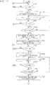
- Fig. 1 shows the basic configuration according to an embodiment.
- Fig. 1 shows a sound signal processing section 1, a microphone 4, a microphone amplifier 5, an A/D converter 6, and a normal processing system 7.
- the sound signal processing section 1 includes a sliding operation detecting section 2 and a control section 3.
- the sound signal processing section 1 corresponds to a sound signal processing apparatus according to an embodiment of the present disclosure.
- the sound signal processing section 1 is formed by, for example, a central processing unit (CPU) or a digital signal processor (DSP).
- a sound signal collected by the microphone 4 is amplified by the microphone amplifier 5, before undergoing analog-digital conversion in the A/D converter 6. Then, the sound signal converted into a digital signal is inputted to the normal processing system 7 and the sound signal processing section 1.
- normal processing system 7 refers to a processing section for functions normally associated with a sound signal in electronic equipment to which a sound signal is inputted from the microphone 4.
- the microphone 4 is already provided for various purposes. Alternatively, a separate microphone 4 can be connected to consumer electronic equipment.
- consumer electronic equipment examples include a digital camera equipped with a sound recording function as well as a picture recording function, an IC recorder, an information processing apparatus such as a personal computer having a voice communication function, mobile equipment, and a noise-cancelling headphone (hereinafter, "NC headphone").
- a digital camera equipped with a sound recording function as well as a picture recording function
- an IC recorder an information processing apparatus such as a personal computer having a voice communication function, mobile equipment, and a noise-cancelling headphone (hereinafter, "NC headphone").
- NC headphone noise-cancelling headphone
- a processing system is provided with respect to a microphone input sound signal in accordance with its function.
- sections that perform processing such as compression for sound recording, encoding for recording, and recording to the recording medium make up the normal processing system 7 shown in Fig. 1 .
- the functional portion that performs a noise cancellation process corresponds to the normal processing system 7.
- the normal processing system 7 performs processing according to these functions, with respect to an inputted sound signal.
- the sound signal processing section 1 performs detection of a sliding operation with respect to an inputted sound signal, thereby detecting an operation input made by the user.
- the sliding operation detecting section 2 detects the start and end of a user's sliding operation solely through processing on the temporal axis.
- the sliding operation detecting section 2 determines that a sliding operation has started. At this time, the sliding operation detecting section 2 outputs a sliding start detection signal SdetS to the control section 3.
- the sliding operation detecting section 2 determines that the sliding operation has ended. At this time, the sliding operation detecting section 2 outputs a sliding end detection signal SdetE to the control section 3.
- the time from the determination of the start to the determination of the end is determined as the period during which the sliding operation is continued.
- the sliding start detection signal SdetS and the sliding end detection signal SdetE may take various conceivable signal forms.
- the sliding start detection signal SdetS and the sliding end detection signal SdetE may not necessarily be two independent lines of signals but may be any such signal that allows the control section 3 to recognize the start and end of sliding.
- the control section 3 is equipped with the function of performing a control process in accordance with at least a user operation in electronic equipment.
- the control section 3 recognizes that the start of a sliding operation has been detected by the sliding operation detecting section 2, the control section 3 starts a predetermined control process that is set with respect to the sliding operation.
- control section 3 When, on the basis of a sliding end detection signal SdetE, the control section 3 recognizes that the end of the sliding operation has been detected by the sliding operation detecting section 2, the control section 3 ends the control process being executed.
- control section 3 performs a predetermined control process while recognizing the length of the period from the sliding start detection signal SdetS to the sliding end detection signal SdetE, that is, the length of the period during which the user is continuing the sliding operation, as an operation quantity.
- control process executed varies for each kind of electronic equipment, examples of control process will be described later in the description of specific embodiments of electronic equipment.
- control process executed varies for each kind of electronic equipment, examples of control process will be described later in the description of specific embodiments of electronic equipment.
- volume Up/Down control control of fast forward playback or rewind playback, and the like are conceivable.
- turning up/down of the volume of playback sound, or the like is implemented by the user performing a sliding operation on the microphone 4.
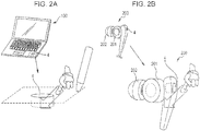
- Figs. 2A and 2B illustrate how a sliding operation is performed.
- Fig. 2A shows a personal computer 100.
- the microphone 4 is provided in the flat portion of the housing near the keyboard.
- the user performs a sliding operation so as to trace the top surface of the microphone 4 or its vicinity, with a finger or a sliding tool such as a pen-shaped pointer.
- the sound produced by the sliding operation is collected by the microphone 4, and is supplied to the sliding operation detecting section 2 in accordance with the configuration as shown in Fig. 1 .
- the sliding operation detecting section 2 determines the start/end of the sliding operation by observing the amplitude or energy level (the absolute value of the amplitude) of the sliding sound signal component of the inputted sound signal.
- Fig. 2B shows a part of a headphone (earphone) 200 that is provided with the microphone 4 for the purpose of noise cancelling, for example.
- the headphone 200 has a headphone driver 201, and an earpiece 202 that is the portion inserted by the user into his/her ear.
- the microphone 4 is provided on the side opposite from the earpiece 202, that is, at a position where the microphone 4 can collect external sound.
- the user performs such a sliding operation as to trace the top surface of the microphone 4 or its vicinity with a finger or the like.
- the sound produced by the sliding operation is collected by the microphone 4, and is supplied to the sliding operation detecting section 2 in accordance with the configuration as shown in Fig. 1 .
- the sliding operation detecting section 2 determines the start/end of the sliding operation by observing the amplitude or energy level (the absolute value of the amplitude) of the sliding sound signal component of the inputted sound signal.
- a sliding operation is such an operation that the user touches and continuously traces the top surface of the microphone 4 or its vicinity in various kinds of electronic equipment with a finger or the like.
- FIGs. 2A and 2B depict a linear sliding operation
- the user may perform a circular (rotary) sliding operation.
- a linear sliding operation can be maintained only for a short time and, as a result, the user may not be able to perform intended control in some cases. In such cases, if the user is made to perform a circular sliding motion around the microphone 4, for example, the user can easily continue the sliding operation.
- the basic configuration according to an embodiment of the present disclosure is as described above with reference to Fig. 1 . That is, an input sound signal from the microphone 4 is inputted to the sound signal processing section 1, and the sound signal processing section 1 detects a user operation by determining a sliding operation. When it is detected that an operation input has been made, a predetermined control process is performed in accordance with the operation.
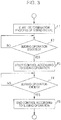
- Fig. 3 shows the procedure of basic processing according to an embodiment.
- step F2 it is determined whether or not a sliding operation has been started. This is a process in the sliding operation detecting section 2. Then, if it is determined that a sliding operation as a user operation input has been started, the processing proceeds from step F2 to F3, and a control process according to the operation input is started as a process in the control section 3.
- step F4 as a process in the sliding operation detecting section 2, it is determined whether or not the user's sliding operation has been ended. Then, if it is determined that the sliding operation has been ended, the processing proceeds from step F4 to F5, and the action according to the operation input which has been executed by the control section 3 is ended.
- NC headphone noise-cancelling headphone
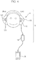
- Fig. 4 schematically shows a noise-cancelling headphone (NC headphone) 10 used by being connected to music playback equipment such as a portable media player 20.
- NC headphone noise-cancelling headphone
- the media player 20 plays back data such as music recorded on an internal recording medium, and outputs two channels, Land R, of sound signals to the connected NC headphone 10.
- the NC headphone 10 includes a headphone section 11 and a noise cancellation section 14.
- the headphone section 11 has L and R channels of speakers 13L and 13R inside respective speaker housings corresponding to the left and right ears of the user.
- Microphones 12L and 12R are provided so as to collect external sounds from the outside of the left and right speaker housings, respectively.
- the headphone section 11 may not be of a type having the speaker housing as shown in the drawing, but may be of an earphone type shown in Fig. 2B , or an ear-pad type. In this example, any of these types may be used as long as the microphones 12L and 12R are provided.
- the NC headphone 10 is not limited to an NC headphone that performs a feedforward noise cancellation process but may be an NC headphone that performs a feedback noise cancellation process.
- the noise cancellation unit 14 is connected to the headphone section 11 provided with the microphones 12L and 12R as mentioned above.
- the noise cancellation unit 14 mixes a noise reduction sound signal into the sound signal of playback music or the like supplied from the media player 20, thereby outputting a sound signal with reduced external noise from each of the speakers 13L and 13R.
- noise reduction is performed as follows.
- the microphones 12L and 12R each attached to the speaker housing collects external noise reaching the user's ear via the speaker housing. From the sound signal of the external noise collected by each of the microphones 12L and 12R, the noise cancellation unit 14 generates a noise reduction sound signal of acoustically opposite phase to the external noise. Then, the noise cancellation unit 14 synthesizes the generated noise reduction sound signal with the sound signal of playback music or the like, and supplies the resulting sound signal to each of the speakers 13L and 13R.
- the sound outputted from each of the speakers 13L and 13R contains a component of opposite phase to external noise.
- this opposite phase component and the external noise that actually leaks in via the speaker housing spatially cancel each other out, with the result that as auditorily perceived by the user, the external noise component is reduced and the original output sound of the playback music reaches the user.
- FIG. 5 An example of the internal configuration of the noise cancellation unit 14 is shown in Fig. 5 .
- the noise cancellation unit 14 has microphone amplifiers 31L and 31R, A/D converters 32L and 32R, a main processing section 33 formed by a DSP or CPU, a memory section 40, power amplifiers 42L and 42R, and A/D converters 41L and 41R.
- the main processing section 33 is provided with a noise cancellation section 34, a gain section 35, adders 36L and 36R, a sliding operation detecting section 37, a control section 38, and an equalizer 39.
- the sound signal of playback music or the like from the media player 20 is processed as follows.
- L and R channels of playback sound signals SA-L and SA-R as so-called headphone outputs are supplied.
- the playback sound signals SA-L and SA-R are respectively converted into digital signals by the A/D converters 41L and 41R. Then, in the equalizer 39, these sound signals are subjected to sound quality correction such as amplitude-frequency characteristic correction or phase-frequency characteristic correction, or both.
- the correction process in the equalizer 39 is executed on the basis of a control signal SG3 from the control section 38. For example, designation of frequency characteristics or the like is done by the control signal SG3.
- the playback sound signals SA-L and SA-R that have undergone sound quality correction in the equalizer 39 are respectively added with noise reduction sound signals by the adders 36L and 36R, and supplied to the power amplifiers 42L and 42R, respectively.
- the power amplifiers 42L and 42R may each be made of a digital amplifier, or may be made of a D/A converter and an analog amplifier.
- Outputs from the power amplifiers 42L and 42R serve as driving signals for the speakers 13L and 13R, and sounds based on the playback sound signals SA-L and SA-R are outputted from the speakers 13L and 13R, respectively.
- Sound signals SmL and SmR collected by the microphones 12L and 12R are amplified by the microphone amplifiers 31L and 31 R in the noise cancellation unit 14, and then converted into digital signals in the A/D converters 32L and 32R, respectively.
- the digitized sound signals SmL and SmR outputted from the A/D converters 32L and 32R are supplied to the noise cancellation section 34.
- the noise cancellation section 34 is configured as a digital filter that generates a noise reduction sound signal in the feedforward mode mentioned above.
- the noise cancellation section 34 performs filtering on each of the sound signals SmL and SmR, with a filter factor designated by a control signal SG1 from the control section 38, thereby generating L and R channels of noise reduction sound signals.
- the generated L and R channels of noise reduction sound signals are supplied to the gain section 35.
- the gain section 35 gives a gain to the L and R channels of noise reduction sound signals, with a gain factor designated by the control signal SG1 from the control section 38.
- the L and R channels of noise reduction sound signals from the gain section 35 are supplied to the adders 36L and 36R, and added with the playback sound signals SA-L and SA-R as described above, respectively.
- the noise cancellation unit 14 in this example further is equipped with the function of detecting a user operation made by a sliding operation on the microphone 12L, 12R or its vicinity.
- the sound signals SmL and SmR respectively collected by the microphones 12L and 12R are also supplied to the sliding operation detecting section 37.
- the sliding operation detecting section 37 detects a user's sliding operation on the microphone 12L, 12R and its vicinity solely through processing on the temporal axis. Specifically, when the energy level of the sliding sound signal component in the inputted sound signal SmL, SmR has continued to exceed a predetermined value for a first time or more, the sliding operation detecting section 37 determines that a sliding operation has been started. Then, to notify the start of operation input by the user, the sliding operation detecting section 37 outputs a sliding start detection signal SdetS to the control section 38.
- the sliding operation detecting section 37 determines that the sliding operation has been ended. Then, to notify the end of operation input by the user, the sliding operation detecting section 37 outputs a sliding end detection signal SdetE to the control section 38.
- the control section 38 controls the individual sections of the noise cancellation unit 14 by the above-mentioned control signals SG1, SG2, and SG3. Also, the control section 38 can also transmit a control signal SG4 to the media player 20.
- control section 38 is equipped with the function of performing a control process in accordance with a user's sliding operation. That is, the control section 38 performs a predetermined control process that is set with respect to the sliding operation, during the period in which the sliding operation as grasped by the sliding start detection signal SdetS and the sliding end detection signal SdetE is being executed. For example, in response to detection of an operation inputted by a sliding operation, the control section 38 transmits operation input information to the media player 20 as the control signal SG4.
- the memory section 40 stores information to be referenced by the control section 38 when performing a control process.
- the memory section 40 stores information on the filter factors in the noise cancellation section 34 and the equalizer 39, and so on.
- control section 38 performs a predetermined control in accordance with a user's sliding operation.
- a real-time, continuous control is suited for the control process. The following are assumed as examples of such control.
- control section 38 performs the process of transmitting a necessary command to the media player 20 during the sliding operation period detected by the sliding operation detecting section 37.
- the control section 38 performs the process of transmitting a "Volume up” or "Volume down" command to the media player 20, in response to detection of a sliding operation by the sliding operation detecting section 37.
- control section 38 transmits a predetermined command to the media player 20 in response to detection of each of those sliding operations.
- the microphones 12L and 12R are usually mounted close to the ears.
- the user is able to control the action of the media player 20 by simply performing a sliding operation on the microphone 12L, 12R, without taking the main body of the media player 20 out during a commute or the like, for example.
- control section 38 it is also conceivable for the control section 38 to perform internal control of the noise cancellation unit 14 in response to detection of a sliding operation.
- control section 38 may be configured to switch the filter factor of the noise cancellation section 34 by control using the control signal SG1, in response to a sliding operation. For example, it is also possible to control such an action as to sequentially switch the filter factor in short time units during the sliding operation period so that the user can select the filter characteristic suited for the current condition.
- the noise environment characteristic varies greatly depending on the environment of each individual location such as an airfield, the platform of a train station, the inside of a train, a factory, or the like, even when observed as a frequency characteristic. Therefore, as the filter characteristic for noise reduction, it is desired to use the optimal filter characteristic suited to each individual noise environment characteristic. For this reason, it is advantageous to allow the user to sequentially switch to and select the most suitable filter characteristic by performing a sliding operation on the microphone 12L, 12R.
- control section 38 may be configured to switch the gain factor of the gain section 35 by control using the control signal SG2, in response to a sliding operation. This allows the user to adjust the noise cancellation level in an arbitrary fashion through an easy operation.
- control section 38 may be configured to change the filter factor in the equalizer 39 by control using the control signal SG3, in response to detection of a sliding operation. For example, it is also possible to control such an action as to sequentially switch the equalizing characteristic in short time units during the sliding operation period so that the user can select a preferred characteristic. This allows the user to select a sound quality correction state through an easy operation. For example, it is advantageous to store various preset frequency characteristics in the memory section 40 in advance, and allow the user to sequentially apply equalizer characteristics that provide a preferred sound quality and select a suitable characteristic at the end of the sliding operation.
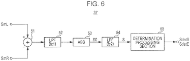
- This Configuration Example I represents a configuration example in which a sliding operation is detected in a manner common to the sound signals SmL and SmR from the microphones 12L and 12R.
- the sliding operation detecting section 37 includes an adder 51, a low-pass filter 52, an absoluteizing circuit 53, a low-pass filter 54, and a determination processing section 55.
- the respective sound signals SmL and SmR from the microphones 12L and 12R are added together in the adder 51 and inputted to the low-pass filter 52.
- the cut-off frequency of the low-pass filter 52 is set to fc1.
- This cut-off frequency fc1 is set to a frequency for extracting a sliding sound signal component.
- the cut-off frequency is set to such a frequency that makes it possible to extract the sound signal component produced when a finger is traced over the resin material. Therefore, a cut-off frequency fc1 suited for the kind of resin being used is determined.
- the filter characteristic is determined in accordance with the material of the microphones 12L and 12R themselves or the material used in their surroundings.
- a sliding sound produced near the microphone is the predominant component in the sound signal SmL or SmR. It should be noted, however, that the sound signals SmL and SmR also contain broad-bandwidth noise such as background noise and ambient noise. Accordingly, first, the sliding sound signal component is extracted with the low-pass filter 52.
- the sound signal component of a sound produced by a sliding motion has high energy in low frequencies.
- the sliding sound signal component in the summed signal of the sound signals SmL and SmR outputted from the low-pass filter 52 is absoluteized in the absoluteizing circuit 53.
- the signal S0 absoluteized in the absoluteizing circuit 53 is converted into a signal S representing the energy level of the sound signal SmL, SmR via the low-pass filter 54, and inputted to the determination processing section 55.
- the cut-off frequency fc2 of the low-pass filter 54 is set to a frequency for converting the signal S0 into an envelope signal.
- the determination processing section detects the start/end of a sliding operation through processing described later, with respect to the signal S. Then, as a result of the detection, the determination processing section outputs a sliding start detection signal SdetS and a sliding end detection signal SdetE to the control section 38.
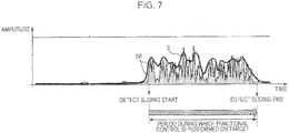
- Fig. 7 shows an example of the waveforms of the signal S0 and signal S when a sliding operation is performed.
- the low-pass filter 52 extracts a sliding sound signal component. Since the output of the low-pass filter 52, which is the sliding sound signal component, has an amplitude with a positive/negative value, in order to determine the negative amplitude as an energy level as well, the signal S0 absoluteized in the absoluteizing circuit 53 is used.
- the energy level of the signal S0 (the amplitude level of the absoluteized sliding sound signal component) becomes high.
- the period during which high energy level continues can be easily determined as the sliding operation period.
- the determining processing section 55 determines the sliding operation period shown in the drawing, that is, the period during which functional control according to the sliding operation is performed with respect to a controlled object.
- Fig. 8 is a flowchart of a process in which the determining processing section 55 determines the start and end of a sliding operation from the signal S.
- the determining processing section 55 performs the sliding operation determination process shown in Fig. 8 with respect to the signal S that is inputted.
- step F101 the determining processing section 55 determines whether or not the level of the signal S is higher than a threshold TH1.
- Fig. 9 shows the waveform of the signal S and thresholds TH1 and TH2.
- the threshold TH1 is a threshold for determining whether or not the energy level of the signal S has increased.
- the threshold TH2 is a threshold for determining whether or not the energy level of the signal S has decreased.
- step F101 the value of the signal S that is inputted is sequentially compared with the threshold TH1. If it is determined that the value of the signal S is equal to or smaller than the threshold TH1, the determining processing section 55 returns to step F101 as indicated by "R", and the next input value of the signal S is compared with the threshold TH1.
- step F102 When the value of the signal S exceeds the threshold TH1, the determining processing section 55 proceeds to step F102.
- step F102 the determining processing section 55 first resets a counter Cn1 to 0, and causes counting to be started.
- the determining processing section 55 performs the determinations in steps F104 and F105.
- step F104 the determining processing section 55 determines whether or not the value of the signal S is larger than the threshold TH1.
- step F105 the determining processing section 55 determines whether or not the value of the counter Cn1 has reached a first time THtm1.
- the first time THtm1 is a predetermined time interval as shown in Fig. 9 . This is set as a time for determining that an increase that has occurred in the energy of the signal S is not momentary but is a continuous increase in energy level due to a sliding operation.
- step F104 If it is detected in step F104 that the signal S is lower than the threshold TH1, it is determined that the increase in energy level detected in step F101 is a momentary one and not caused by a sliding operation, and the determination processing section 55 returns to step F101 as indicated by "R". That is, it is determined that a sliding operation has not been started.
- step F105 the case where it is determined in step F105 that the value of the counter Cn1 has reached the first time THtm1 is a case where it is determined that the state in which the energy level of the signal S is larger than the threshold TH1 has continued.
- the determination processing section 55 proceeds to step F106, and determines that a sliding operation has been started. Then, the determination processing section 55 outputs a sliding start detection signal SdetS to the control section 38.
- step F107 After determining that a sliding operation has been started, the determining processing section 55 proceeds to step F107, and starts determination of the end of the sliding operation.
- step F107 the determination processing section 55 compares the signal S with the threshold TH2, and determines whether or not the signal S has become lower than the threshold TH2.
- the threshold TH2 is set to a slightly lower level than the threshold TH1.
- This threshold TH2 is a value for determining a decrease in the energy level of the signal S.
- the determination processing section 55 regards this as indicating a possibility that the sliding operation has been ended, and proceeds to step F108.
- step F108 the determination processing section 55 resets a counter Cn2 to 0, and causes counting to be started.
- the determining processing section 55 performs the determinations in steps F110 and F111.
- step F110 the determination processing section 55 determines whether or not the signal S has become lower than the threshold TH2.
- step F111 the determination processing section 55 determines whether or not the value of the counter Cn2 has reached the second time Thmt2.
- the second time THtm2 is a predetermined time interval as shown in Fig. 9 . This is set as a time for determining that a decrease that has occurred in the energy of the signal S is not momentary but is a continuous decrease in energy level following the end of the sliding operation.
- step F110 If it is detected in step F110 that the signal S has not become lower than the threshold TH2, it is determined that the decrease in energy level detected in step F107 is a momentary one and not caused by ending of the sliding operation, and the determination processing section 55 returns to step F107 as indicated by "Q". That is, it is determined that the sliding operation has not been ended.
- Fig. 9 shows, as a period tmA, a state in which, after the start of sliding, the energy level of the signal S has temporarily decreased below the threshold TH2.
- the period tmA is a period shorter than the second time THtm2.
- the decrease is determined as a temporary decrease in level during the sliding operation.
- a sliding operation performed by the user is not necessarily a regular sliding motion.
- the sliding motion is not performed with a fixed force at a constant speed.
- momentary stoppage of the sliding motion due to a finger getting stuck or the like during sliding is a common occurrence.
- the second time THtm2 is set, and if the period during which the decrease has occurred is less than the second time THtm2, it is determined that the sliding operation has not been ended.
- step F111 the case where it is determined in step F111 that the value of the counter Cn2 has reached the second time THtm2 is a case where it is determined that the state in which the energy level of the signal S is smaller than the threshold TH2 has continued.
- the determination processing section 55 proceeds to step F112, and determines that the sliding operation has been ended. Then, the determination processing section 55 outputs a sliding end detection signal SdetE to the control section 38.
- the determination processing section 55 determines the start/end of a sliding operation in the manner as described above with reference to Fig. 8 . This allows the control section 38 to recognize the period during which the sliding operation is being performed, thereby enabling a control based on a sliding operation as a continuous operation or an operation for which an operation quantity is specified.
- the determining processing section 55 determines the start/end of a sliding operation by observing an increase/decrease in energy level on the temporal axis. This makes it possible to determine a sliding operation easily without causing an increase in resources.
- a sliding operation When a sliding operation is performed, the energy level (amplitude) of a sound signal of a predetermined band (sliding sound signal component) in a microphone input signal increases. Accordingly, by monitoring the energy of the sliding sound signal component, a sliding operation can be detected by determining an increase/decrease in energy, without performing a waveform analysis.
- the detection process is simple, the time necessary for detecting the start or end of a sliding operation is shortened, thereby enabling the action of the apparatus with good response.
- the user may perform a sliding operation on either one of the left and right microphones 12L and 12R.
- control section 38 performs a control according to the kind of operation assigned to this sliding operation, for example, the control illustrated above.
- control section 38 is to transmit a command for controlling the action of the media player 20, the user is able to operate the media player 20 while keeping the media player 20 in a pocket or a bag during a commute or the like.
- the operation method used is such that a sliding motion is made with a finger or the like, it is possible to intuitively control the media player 20 or the noise cancellation unit 14.
- the mode used is such that a sliding motion is made on the microphone 12L, 12R or its vicinity
- implementation is possible as long as there are an ordinary (inexpensive) microphone and a signal processing section such as a CPU/DSP even without using a special sensor such as a touch sensor, which contributes to reducing cost.
- the headphone section 11 is provided with the microphones 12L and 12R for the noise cancellation function. Since a sliding operation can be performed using the microphones 12L and 12R, it is unnecessary to provide an additional sensor device for operation input.
- This configuration example is suited for cost reduction also in this respect, and also does not cause an increase in the number of components that make up the apparatus.
- the sound signals SmL and SmR from the respective L and R channels of microphones 12L and 12R are synthesized to determine a sliding operation, only one of the channels of sound signals (for example, the sound signal SmL) may be inputted to the low-pass filter 52. In that case, only the microphone 12L on the corresponding channel is used for the purpose of the sliding operation.
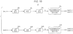
- the sliding operation detecting section 37 as Configuration Example II will be described with reference to Fig. 10 .
- Configuration Example II is an example in which the L channel and the R channel, that is, the microphones 12L and 12R can be assigned to different operations.
- this configuration example is such that a sliding operation on the microphone 12L can be assigned to Volume up, and a sliding operation on the microphone 12R can be assigned to Volume down.
- the sliding operation detecting section 37 adopts two independent lines of sliding operation detection configurations for the L channel and the R channel.
- a low-pass filter 52L, an absoluteizing circuit 53L, a low-pass filter 54L, and a determination processing section 55L are provided for the sound signal SmL from the microphone 12L.
- a low-pass filter 52R, an absoluteizing circuit 53R, a low-pass filter 54R, and a determination processing section 55R are provided for the sound signal SmR from the microphone 12R.
- the determination processing sections 55L and 55R may each perform the process of determining the start/end of a sliding operation as shown in Fig. 8 , for example.
- the determination processing section 55L Upon detecting the start of a sliding operation with respect to a signal S obtained from the sound signal SmL, the determination processing section 55L outputs a sliding start detection signal SdetS(L) to the control section, and upon detecting the end of the sliding operation 38, the determination processing section 55L outputs a sliding end detection signal SdetE(L) to the control section 38.
- the determination processing section 55R Upon detecting the start of a sliding operation with respect to a signal S obtained from the sound signal SmR, the determination processing section 55R outputs a sliding start detection signal SdetS(R) to the control section 38, and upon detecting the end of the sliding operation, the determination processing section 55R outputs a sliding end detection signal SdetE(R) to the control section 38.
- the control section 38 can recognize two kinds of operation inputs on the basis of the sliding start detection signal SdetS(L) and the sliding end detection signal SdetE(L), and the sliding start detection signal SdetS(R) and the sliding end detection signal SdetE(R). Therefore, for example, the above-mentioned Volume Up/Down control or the like can be performed in accordance with those operation inputs.
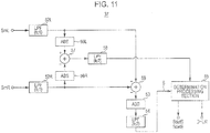
- Configuration Example III is shown in Fig. 11 .
- the L channel and the R channel that is, the microphones 12L and 12R can be assigned to different operations.
- the sliding operation detecting section 37 is simply installed with two lines of sliding operation detection processing systems, and thus the load on the configuration is large. Configuration Example III can reduce the load on the configuration.
- the sliding operation detecting section 37 performs a channel determination process which determines a channel that contains a sliding sound signal component from among a plurality of channels of sound signals SmL and SmR, and a sliding operation start/end determination process with respect to a sound signal obtained by adding or subtracting sliding sound signal components from the plurality of channels to or from each other. A sliding operation, and the channel on which the sliding operation has been performed can be thus detected.
- the sound signal SmL from the microphone 12L is inputted to the low-pass filter 52L, and a sliding sound signal component is extracted with the cut-off frequency fc1.
- the sound signal SmR from the microphone 12R is inputted to the low-pass filter 52R, and a sliding sound signal component is extracted with the cut-off frequency fc1.
- the output of the low-pass filter 52L is supplied to an absoluteizing circuit 56L and a subtractor 59.
- the output of the low-pass filter 52R is supplied to an absoluteizing circuit 56R and the subtractor 59.
- the absoluteizing circuit 56L Absolutizes the output of the low-pass filter 52L, and supplies the resulting output to a subtractor 57.
- the absoluteizing circuit 56R absoluteizes the output of the low-pass filter 52R, and supplies the resulting output to the subtractor 57.
- the output of the subtractor 57 is converted into an envelope signal by a low-pass filter 58 with the cut-off frequency fc2, and supplied to the determination processing section 55.
- the determination processing section 55 when a sliding operation is performed on either the microphone 12L or 12R, it is possible to detect on which of the microphones 12L and 12R the sliding operation has been performed, by determining whether the envelope signal is positive or negative.
- the respective sliding signal components in the sound signals SmL and SmR extracted with the low-pass filters 52L and 52R are subjected to a subtraction process in the subtractor 59, and their difference value is extracted.
- This output of the subtractor 59 is absoluteized in the absoluteizing circuit 53, converted into an enveloped signal S by the low-pass filter 54 with the cut-off frequency fc2, and supplied to the determination processing section 55.
- the determination processing section 55 performs a sliding operation determination process with respect to the signal S, and outputs a sliding start detection signal SdetS, a sliding end detection signal SdetE, and an L-channel/R-channel determination signal D-LR to the control section 38 in accordance with the determination process with respect to the signal S.
- the determination process in the determination processing section 55 in this case may be performed in the manner as shown in Fig. 12 , for example.
- steps F101 to S106 the start of a sliding operation is determined in the same manner as in Fig. 8 .
- step F106 determines whether sliding has been started. If it is determined in step F106 that sliding has been started, the determination processing section 55 performs L/R determination in step F130.
- This L/R determination is a process that detects on which of the microphones 12L and 12R a sliding operation has been performed. Then, the determination processing section 55 outputs an L-channel/R-channel determination signal D-LR indicating the result of the L/R determination to the control section 38.
- a sliding start detection signal SdetS and a determination signal D-LR are supplied to the control section 38.
- the determination processing section 55 determines the end of the sliding operation in steps F107 to F111 in the same manner as in Fig. 8 .
- step F112 the determination processing section 55 outputs a sliding end detection signal SdetE to the control section 38.
- control section 38 can recognize two kinds of operation inputs made by using the microphones 12L and 12R separately, on the basis of a sliding start detection signal SdetS, a sliding end detection signal SdetE, and a determination signal D-LR, thereby allowing Volume Up/Down control or the like to be performed in accordance with those operation inputs, for example.
- a sliding operation is such as operation as to simply trace the area where the microphone 4 is formed.
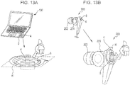
- FIGs. 13A and 13B each show a configuration in which a sliding guide 8 is provided in the vicinity of the microphone 4.
- Fig. 13A shows a case in which the microphone 4 is provided in a predetermined area on the housing of the personal computer 100.
- the sliding guide 8 having a ring-like shape is formed around the microphone 4.
- Fig. 13B also shows, for example, a part of the headphone (earphone) 200 provided with the microphone 4 for the purpose of noise cancellation.
- the sliding guide 8 having a ring-like shape is formed around the microphone 4.
- the sliding guide 8 may be simply any structural part that can be tactilely recognized by the user.
- the sliding guide 8 is formed in a projected or recessed shape so as to be able to guide the sliding motion made with a user's finger. That is, the sliding guide 8 may be any structure that is mounted for the purpose of allowing the user to smoothly move a finger or the like in a circular fashion while being aware of the sliding guide 8.
- a recessed, that is, ring-like groove is formed around the microphone 4
- a projected (rail-like) ring may be formed as well.
- a sliding operation is easy if the user is to make the sliding operation in a rotary fashion (in the manner of drawing a circle).
- the sliding guide 8 having a ring-like shape is provided in this way, the user can perform a rotary sliding operation more easily. That is, when the user rotates a finger while touching the sliding guide 8 with the fingertip, the resulting motion becomes a sliding operation.
- the provision of the sliding guide 8 can eliminate situations in which the user performs a sliding operation at a position far from the microphone 4 and thus the operation is not determined appropriately, or the user does not know where a sliding motion should be made.
- the sliding guide 8 may have a linear or bowed shape.
- the sliding guide 8 may have a ring shape or linear shape that is partially cut away.
- FIGs. 14A and 14B illustrate an example in which a directional sound source section 9 that produces different sound signal components depending on the direction of a sliding operation is provided in the vicinity of the microphone 4.
- Figs. 14A and 14B also show examples of the personal computer 100 and the headphone 200, respectively.
- the portion around the microphone 4 serves as the directional sound source section 9.
- the directional sound source section 9 is a portion of a material or structure that produces different sounds depending on the sliding direction.
- Figs. 15A to 15C An example of the directional sound source section 9 is shown in Figs. 15A to 15C .
- Fig. 15A shows one that has such a material structure that produces sound by mutual contact, is fibrous, and has springiness at the root. This may be a material having such properties, or may be a structure made from a mold or the like.
- the directional sound source section 9 has such a property that when a sliding operation is performed to the right as shown in Fig. 15B , for example, mutual contact readily occurs and sound is readily produced, but when a sliding operation is performed to the left as shown in Fig. 15C , no mutual contact occurs and thus sound is hardly produced.
- the frequency characteristic of the produced sound varies depending on the direction of the sliding operation.
- Examples of the direction sound source section 9 include one made of hair such as pig hair, one woven in a thread or fabric form with nylon, polypropylene, polyolefine, ABS, glass fiber, FRP, or the like, and one made of a material such as a substance subjected to a fabric finish that fluffs up the both sides of a textile, such as a velvet or velour fabric made from not only hair or silk but also cotton, rayon, acetate, or the like.
- a structure made of a material such as metal, rubber, or resin, or a combination of such materials can be also made to produce different sounds when touched from different directions depending on its structural shape, and thus can be used as the direction sound source section 9.
- FIGs. 15A to 15C mentioned above are directed to the case of sliding in one direction and in a direction opposite to the direction, as described above, there are a variety of conceivable materials and structures that produce different sounds depending on the sliding direction.
- the sound can be made to differ not only between the forward and reverse directions of sliding as shown in Figs. 15A to 15C but also between an X-direction and a Y-direction orthogonal to the X-direction. Furthermore, the sound can be made to differ between the X-direction, the Y-direction, and a diagonal direction.
- the sound can be also made to differ between a forward X-direction (X1), a reverse X-direction (X2), a forward Y-direction (Y1), and a reverse Y-direction (Y2).
- Figs. 14A and 14B each show a case in which the directional sound source section 9 of such a material or structure that produces different sounds between sliding in the X-direction and sliding in the Y-direction.
- the produced sound differs between when making a to-and-fro sliding motion in the X-direction and when making a to-and-fro sliding motion in the Y-direction.
- the sliding operation detecting section 2 illustrated in Fig. 1 can determine not only the start/end of a sliding operation but also whether the sliding operation is performed in the X-direction or in the Y-direction.
- the control section 3 can perform a control process according to the determination.
- Fig. 16 shows an example of the configuration of the sound signal processing section 1 designed to detect the sliding direction, in particular, the configuration of the sliding operation detecting section 2 in the case where the directional sound source section 9 is provided in the vicinity of the microphone 4.
- Fig. 16 shows the internal configuration of the sliding operation detecting section 2 in detail, out of the basic configuration shown in Fig. 1 .
- the sliding operation detecting section 2 determines the start and end of the sliding operation, and further detects the direction of the sliding operation from an inputted sound signal.
- control section 3 performs a predetermined control process that is set with respect to the sliding operation direction detected by the sliding operation detecting section, during the period from the start to end of the sliding operation determined by the sliding operation detecting section 2.
- the sliding operation detecting section 2 includes the low-pass filter 52, the absoluteizing circuit 53, the low-pass filter 54, and the determination processing section 55. These components may be considered to be the same as those described in Configuration Examples I, II, and III in the case of the NC headphone 10 described above.
- the low-pass filter 52 extracts a sliding sound signal component from the sound signal obtained with the microphone 4.
- a low-pass filter is assumed here, depending on the material or structure of the directional sound source section 9, there may be cases where it is suitable to use a band-pass filter.
- This sliding sound signal component is absoluteized in the absoluteizing circuit 53, converted into an enveloped signal S with the low-pass filter 54, and supplied to the determination processing section 55.
- the determination processing section 55 is provided with a start/end detection processing block 55a and a sliding direction detection block 55b.
- the start/end detection processing block 55a determines the start and end of a sliding operation from the signal S, and outputs a sliding start detection signal SdetS and a sliding end detection signal SdetE to the control section 3 in accordance with this determination.
- the sliding operation detecting section 2 is also provided with band-pass filters 61-1, 61-2, 61-3, and 61-4, and absoluteizing circuits 62-1, 62-2, 62-3, and 62-4.
- the pass-band center frequency of the band-pass filter 61-1 is set to fc3.
- the pass-band center frequency of the band-pass filter 61-2 is set to fc4.
- the pass-band center frequency of the band-pass filter 61-3 is set to fc5.
- the pass-band center frequency of the band-pass filter 61-4 is set to fc6.
- the absoluteizing circuits 62-1, 62-2, 62-3, and 62-4 supplies signals S1, S2, S3, and S4 obtained by absoluteizing the outputs of the band-pass filters 61-1, 61-2, 61-3, and 61-4, respectively, to the sliding direction detection block 55b in the determination processing section 55.
- the sliding direction detection block 55b observes the characteristic based on the signals S1, S2, S3, and S4.
- the sliding direction detection block 55b For example, in the sliding direction detection block 55b, the tendencies of frequency characteristics are preset for individual sliding directions. These are compared with the signals S1, S2, S3, and S4, and in the same manner as pattern recognition, the direction corresponding to the closest characteristic is determined as the sliding direction. Then, the sliding direction detection block 55b outputs a sliding direction determination signal Sd to the control section 3.
- the processing in the determination processing section 55 including the start/end detection processing block 55a and the sliding direction detection block 55b is as shown in Fig. 17 .
- step F106 determines whether a sliding operation has been started, and a sliding start detection signal SdetS is outputted, as the processing on the sliding direction detection block 55b side.
- the sliding direction detection block 55b compares the signals S1 to S4 with the frequency characteristic patterns that are preset for individual sliding directions, and determines the sliding direction according to which pattern the frequency characteristic based on the current signals S1 to S4 is close to.
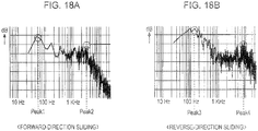
- Figs. 18A and 18B and Figs. 19A and 19B each show an example of how to determine the sliding direction.
- Figs. 18A and 18B show frequency characteristics when sliding is performed in the forward and reverse directions, respectively, in the case where the directional sound source section 9 is in the form of a hook-and-loop fastener.
- Figs. 19A and 19B schematically show a determination process.
- the respective pass-band center frequencies fc3 to fc6 of the band-pass filters 61-1 to 61-4 are set to 50 Hz, 150 Hz, 3 KHz, and 7 KHz corresponding to Peak1 to Peak4 shown in Figs. 18A and 18B mentioned above, respectively.
- the frequency characteristic is such that Peak1 and Peak2 are observed during sliding in the forward direction.
- the frequency characteristic is such that Peak3 and Peak4 are observed during sliding in the reverse direction.
- model patterns corresponding to the signals S1 to S4 are preset in this way.
- the frequency characteristic based on the inputted signals S1 to S4 is regarded as being close to the forward-direction sliding model pattern. Therefore, the sliding direction is determined to be the forward direction.
- Fig. 20A the same applies also in the case of differentiating between sliding operations in the forward X-direction (X1), the reverse X-direction (X2), the forward Y-direction (Y1), and the reverse Y-direction (Y2).
- individual frequency characteristic model patterns corresponding to the sliding directions X1, X2, Y1, and Y2 are prepared in advance. Then, by determining which model pattern the frequency characteristic obtained from the respective levels of the inputted signals S1 to S4 is close to, it is possible to discriminate between the sliding directions X1, X2, Y1, and Y2.
- two band-pass filters for the bands A and B may be provided.
- frequency characteristic matching may be performed by dividing the frequency characteristic into five or more bands with five or more band-pass filters.
- step F140 in Fig. 17 the sliding direction detection block 55b determines the sliding direction by, for example, the above-mentioned pattern matching method, and outputs a sliding direction determination signal Sd to the control section 3.
- a sliding start detection signal SdetS and a sliding direction determination signal Sd are supplied to the control section 38.
- the determination processing section 55 determines the end of the sliding operation in steps F107 to F111 in the same manner as in the case of Fig. 8 .
- the determination processing section 55 outputs a sliding end detection signal SdetE to the control section 38 in step F112.
- the control section 38 can recognize a plurality of kinds of operation inputs in accordance with the sliding direction with respect to the microphone 4. Therefore, different control processes, for example, controls such as Volume Up/Down, can be performed in accordance with those operation inputs.
- two or more operation inputs can be made by a sliding operation on a single microphone 4.
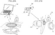
- Figs. 21A and 21 B each illustrate a case in which both the sliding guide 8 and the directional sound source section 9 are provided.
- Figs. 21A and 21B also show examples of the personal computer 100 and headphone 200 as in Figs. 2A and 2B , Figs. 13A and 13B , and Figs. 14A and 14B , respectively, in Figs. 21A and 21B , the sliding guide 8 is formed as the directional sound source section 9.
- a projected (rail-like) sliding guide 8 is formed in a ring shape around the microphone 4.
- the material or structure of the sliding guide 8 is such that the direction sound source section 9 that produces different sounds in the forward and reverse directions.
- the user can make an operation input while differentiating between clockwise sliding and counter-clockwise sliding operations along the sliding guide 8.
- the sliding operation detecting section 2 may be configured to determine the start/end of a sliding operation, and the sliding direction as in Fig. 17 .
- control section 3 can perform a control process according to the sliding direction.
- control process for example, such intuitive operations as would be used in ordinary AV equipment, including Volume Up/Down, and Advance/Return of channels or playback content, become possible for enhanced user convenience.
- the sliding guide 8 may have a linear or bowed shape.
- the sliding guide 8 may have a ring shape or linear shape that is partially cut away.
- Fig. 22A shows an example in which two ring-like sliding sound source sections 8a and 8b are provided around the microphone 4.
- Fig. 22B shows an example in which two linear sliding sound source sections 8a and 8b are provided near the microphone 4.
- the sliding sound source sections 8a and 8b differ in material and shape from each other, and produce different when sliding is performed.
- the sliding operation detecting section 2 detects the location of a sliding operation from an input sound signal. That is, by a determination process using a sliding sound signal component produced by the sliding operation, the sliding operation detecting section 2 determines the start and end of the sliding operation, and further, detects the location where the sliding operation has been performed from the inputted sound signal.
- Detecting the location where the sliding operation has been performed means determining on which of the sliding sound source sections 8a and 8b the sliding operation has been performed. Since the sliding sound source sections 8a and 8b produce different when sliding is performed, in this case as well, the configuration and processing as shown in Fig. 16 may be employed.
- the location of sliding can be determined by pattern matching of the frequency characteristics of sounds obtained with the respective sliding sound source sections 8a and 8b. Then, in accordance with determination of the start and end of the sliding operation, the sliding operation detecting section 2 outputs a sliding start detection signal SdetS and a sliding end detection signal SdetE to the control section 3, and also outputs a determination signal of the sliding location.
- control section 3 can recognize on which of the sliding sound source sections 8a and 8b the sliding operation has been performed from the determination signal of the sliding location, the control section 3 can perform a control process that differs in accordance with this recognition.
- control section 8 performs a control such as Volume up when the sliding sound source section 8a is operated, and Volume down when the sliding sound source section 8b is operated.
- the function of the noise cancellation unit 14 is built in the media player 20.
- the media player 20 is the specific apparatus installed with the sound signal processing section 1 according to an embodiment of the present disclosure, and can provide the same effect as that of the NC headphone 10 described above.
- the microphone 4 in that case may be installed in a headphone apparatus being connected, or may be separate microphone equipment from a headphone apparatus connected to a microphone input terminal.
- a microphone is built in the main body of the media player 20, that microphone may be used.
- the microphone 4 is provided, so the configuration as shown in Fig. 1 can be easily implemented. In that case, it is conceivable to apply a sliding operation on the microphone 4 to an adjustment of the recording microphone level, or the like.
- imaging equipment such as digital still cameras and video cameras also come installed with a microphone.
- Providing such imaging equipment with the configuration shown in Fig. 1 enables operation inputs to be made using a microphone.
- a sliding operation to perform a scroll operation when playing back or searching for captured images.
- a sliding operation for, for example, doing a zoom on an object to be captured, or a camera zoom operation.
- a sliding operation on the microphone 4 can be used to do an operation related to the game.
- a sliding operation on the microphone 4 can be used to do a scroll operation for channel selection, a volume control operation, or the like.
- the present disclosure is also applicable to a personal computer, a portable information processing apparatus (for example, a personal digital assistant (PDA)), a portable telephone, or the like.
- a personal computer for example, a personal digital assistant (PDA)
- PDA personal digital assistant
- an operation input can be made by doing a sliding operation on the microphone.
- a stereo microphone for communication installed in personal computers or mobile PCs, it is possible to recognize an operation by detecting a sliding operation, and perform a predetermined process. For example, it is conceivable to assign a sliding operation to a mouse operation, a pointing operation, a scroll operation, or the like.
- a microphone is provided of course.
- the present disclosure can be applied without the burden of installing a microphone device anew.
- the present disclosure can be suitably applied to a scroll operation when searching through telephone numbers, addresses, the names of transmit destinations, and so on.
- the present disclosure is also applicable to various kinds of communication apparatus, audio-visual (AV) equipment, consumer electronic equipment, and so on.
- AV audio-visual
- a microphone is mounted in mobile equipment with high portability, such as NC headphones, media players, portable telephones, mobile PCs, and portable game machines. For this reason, it is advantageous to be able to obviate mounting of switches that occupy a large space.
- a variety of operations can be assigned by combining an intermittent sliding operation, the sliding operation interval, and the like, in addition to the differentiation regarding on which microphone a sliding operation is performed, the direction of sliding, the location of sliding, and the like described above.
- the sliding sound produced differs between when performing the sliding operation with the thick of the finger and when performing the sliding operation with the tip of the nail. That is, the frequency characteristic of the resulting sliding sound signal component differs.
- these two cases can be differentiated from each other by the sliding operation detecting section 2 when determining a sliding operation. Therefore, it is also conceivable to assign different operations depending on whether the sliding operation in question has been performed with the thick of the finger or the nail, thereby increasing the kinds of operations that can be made by a sliding operation.
- the microphone it is possible to not only employ a microphone used for another sound input function but also provide a microphone dedicated to sliding operation input. If a large number of microphones for operation input can be provided, many kinds of operation inputs can be made using the microphones.
- the microphone used for the sliding operation may be either of a stereo microphone, a monophonic microphone, and a multi-channel microphone.
- the sliding operation detecting section 2, 37 outputs a sliding start detection signal SdetS and a sliding end detection signal SdetE.
- Those signals may take any such signal form that allows the control section 3, 38 to recognize the start and end of a sliding operation.
- the sliding start detection signal SdetS and the sliding end detection signal SdetE may each be a signal of H level pulse, or a pulse that rises to H level at the start of sliding and drops to L level at the end of sliding. That is, the pulse is such a pulse that continuously becomes H level during the sliding operation period.
- the pulse logic may be reversed.
- the signal form may be such that high frequency pulses are repeatedly outputted during the sliding operation period.
- a program according to an embodiment of the present disclosure is a program for causing an arithmetic processing apparatus to execute a sliding operation detecting step and a controlling step.
- the sliding operation detecting step determines the start and end of a sliding operation by a determination process using a sliding sound signal component in a sound signal collected by an integral or separately connected microphone.
- the sliding sound signal component is produced by the sliding operation on the microphone itself or its vicinity.
- the controlling step performs a predetermined control process that is set with respect to the sliding operation, during the period from the start to the end of the sliding operation determined in the sliding operation detecting step.
- the sound signal processing apparatus is implemented as the control section (arithmetic processing apparatus) in each of the various kinds of equipment described above operates on the basis of such a program. That is, the processes in Figs. 3 and 8 (or Fig. 12 , Fig. 17 , or the like) are executed.
- Such a program can be previously recorded on a HDD that serves as a recording medium built in equipment such as a personal computer, a ROM in a microcomputer having a CPU, a flash memory, or the like.
- the program can be temporarily or permanently stored (recorded) on a removable recording medium such as a flexible disk, a compact disc read only memory (CD-ROM), a magnet optical (MO) disc, a DVD, a Blur-ray disc, a semiconductor memory, or a memory card.
- a removable recording medium such as a flexible disk, a compact disc read only memory (CD-ROM), a magnet optical (MO) disc, a DVD, a Blur-ray disc, a semiconductor memory, or a memory card.
- a removable medium can be provided as so-called packaged software.
- the program can be also downloaded from a download site via a network such as a local area network (LAN) or the Internet.
- LAN local area network
- the present disclosure it is possible to recognize a continuous operation or such an operation for which an operation quantity can be specified, and perform the corresponding control, while using a microphone as an operation input device.
- a continuous operation or an operation for which an operation quantity is specified the user is able to perform an operation that is easy and intuitive, an operation with good response, and the like by using the microphone, thereby significantly improving usability.
Landscapes
- Engineering & Computer Science (AREA)
- Physics & Mathematics (AREA)
- General Engineering & Computer Science (AREA)
- Theoretical Computer Science (AREA)
- Acoustics & Sound (AREA)
- Human Computer Interaction (AREA)
- General Physics & Mathematics (AREA)
- Signal Processing (AREA)
- Circuit For Audible Band Transducer (AREA)
- Details Of Audible-Bandwidth Transducers (AREA)
- Headphones And Earphones (AREA)
Applications Claiming Priority (1)
| Application Number | Priority Date | Filing Date | Title |
|---|---|---|---|
| JP2010125501A JP5593851B2 (ja) | 2010-06-01 | 2010-06-01 | 音声信号処理装置、音声信号処理方法、プログラム |
Publications (3)
| Publication Number | Publication Date |
|---|---|
| EP2393305A2 EP2393305A2 (en) | 2011-12-07 |
| EP2393305A3 EP2393305A3 (en) | 2014-09-17 |
| EP2393305B1 true EP2393305B1 (en) | 2017-03-15 |
Family
ID=44530007
Family Applications (1)
| Application Number | Title | Priority Date | Filing Date |
|---|---|---|---|
| EP11165430.7A Not-in-force EP2393305B1 (en) | 2010-06-01 | 2011-05-10 | Sound signal processing apparatus, microphone apparatus, sound signal processing method, and program |
Country Status (8)
Families Citing this family (78)
| Publication number | Priority date | Publication date | Assignee | Title |
|---|---|---|---|---|
| JP5716287B2 (ja) | 2010-04-07 | 2015-05-13 | ソニー株式会社 | 音声信号処理装置、音声信号処理方法、プログラム |
| JP5593852B2 (ja) | 2010-06-01 | 2014-09-24 | ソニー株式会社 | 音声信号処理装置、音声信号処理方法 |
| JP5593851B2 (ja) | 2010-06-01 | 2014-09-24 | ソニー株式会社 | 音声信号処理装置、音声信号処理方法、プログラム |
| US8908877B2 (en) | 2010-12-03 | 2014-12-09 | Cirrus Logic, Inc. | Ear-coupling detection and adjustment of adaptive response in noise-canceling in personal audio devices |
| JP5937611B2 (ja) | 2010-12-03 | 2016-06-22 | シラス ロジック、インコーポレイテッド | パーソナルオーディオデバイスにおける適応ノイズキャンセラの監視制御 |
| US9824677B2 (en) | 2011-06-03 | 2017-11-21 | Cirrus Logic, Inc. | Bandlimiting anti-noise in personal audio devices having adaptive noise cancellation (ANC) |
| US8958571B2 (en) * | 2011-06-03 | 2015-02-17 | Cirrus Logic, Inc. | MIC covering detection in personal audio devices |
| US9214150B2 (en) | 2011-06-03 | 2015-12-15 | Cirrus Logic, Inc. | Continuous adaptation of secondary path adaptive response in noise-canceling personal audio devices |
| US8948407B2 (en) | 2011-06-03 | 2015-02-03 | Cirrus Logic, Inc. | Bandlimiting anti-noise in personal audio devices having adaptive noise cancellation (ANC) |
| US9318094B2 (en) | 2011-06-03 | 2016-04-19 | Cirrus Logic, Inc. | Adaptive noise canceling architecture for a personal audio device |
| US9076431B2 (en) | 2011-06-03 | 2015-07-07 | Cirrus Logic, Inc. | Filter architecture for an adaptive noise canceler in a personal audio device |
| US9325821B1 (en) * | 2011-09-30 | 2016-04-26 | Cirrus Logic, Inc. | Sidetone management in an adaptive noise canceling (ANC) system including secondary path modeling |
| US9208772B2 (en) * | 2011-12-23 | 2015-12-08 | Bose Corporation | Communications headset speech-based gain control |
| CN102547511B (zh) * | 2011-12-28 | 2014-11-26 | 谭青松 | 耳机控制方法及耳机 |
| US9781529B2 (en) | 2012-03-27 | 2017-10-03 | Htc Corporation | Electronic apparatus and method for activating specified function thereof |
| US9142205B2 (en) | 2012-04-26 | 2015-09-22 | Cirrus Logic, Inc. | Leakage-modeling adaptive noise canceling for earspeakers |
| US9014387B2 (en) | 2012-04-26 | 2015-04-21 | Cirrus Logic, Inc. | Coordinated control of adaptive noise cancellation (ANC) among earspeaker channels |
| US9076427B2 (en) | 2012-05-10 | 2015-07-07 | Cirrus Logic, Inc. | Error-signal content controlled adaptation of secondary and leakage path models in noise-canceling personal audio devices |
| US9123321B2 (en) | 2012-05-10 | 2015-09-01 | Cirrus Logic, Inc. | Sequenced adaptation of anti-noise generator response and secondary path response in an adaptive noise canceling system |
| US9082387B2 (en) | 2012-05-10 | 2015-07-14 | Cirrus Logic, Inc. | Noise burst adaptation of secondary path adaptive response in noise-canceling personal audio devices |
| US9319781B2 (en) | 2012-05-10 | 2016-04-19 | Cirrus Logic, Inc. | Frequency and direction-dependent ambient sound handling in personal audio devices having adaptive noise cancellation (ANC) |
| US9318090B2 (en) | 2012-05-10 | 2016-04-19 | Cirrus Logic, Inc. | Downlink tone detection and adaptation of a secondary path response model in an adaptive noise canceling system |
| US9225307B2 (en) | 2012-06-28 | 2015-12-29 | Sonos, Inc. | Modification of audio responsive to proximity detection |
| US9532139B1 (en) | 2012-09-14 | 2016-12-27 | Cirrus Logic, Inc. | Dual-microphone frequency amplitude response self-calibration |
| US9134856B2 (en) | 2013-01-08 | 2015-09-15 | Sony Corporation | Apparatus and method for controlling a user interface of a device based on vibratory signals |
| US9107010B2 (en) | 2013-02-08 | 2015-08-11 | Cirrus Logic, Inc. | Ambient noise root mean square (RMS) detector |
| US9369798B1 (en) | 2013-03-12 | 2016-06-14 | Cirrus Logic, Inc. | Internal dynamic range control in an adaptive noise cancellation (ANC) system |
| US9106989B2 (en) | 2013-03-13 | 2015-08-11 | Cirrus Logic, Inc. | Adaptive-noise canceling (ANC) effectiveness estimation and correction in a personal audio device |
| US9414150B2 (en) | 2013-03-14 | 2016-08-09 | Cirrus Logic, Inc. | Low-latency multi-driver adaptive noise canceling (ANC) system for a personal audio device |
| US9215749B2 (en) | 2013-03-14 | 2015-12-15 | Cirrus Logic, Inc. | Reducing an acoustic intensity vector with adaptive noise cancellation with two error microphones |
| US9208771B2 (en) | 2013-03-15 | 2015-12-08 | Cirrus Logic, Inc. | Ambient noise-based adaptation of secondary path adaptive response in noise-canceling personal audio devices |
| US9502020B1 (en) | 2013-03-15 | 2016-11-22 | Cirrus Logic, Inc. | Robust adaptive noise canceling (ANC) in a personal audio device |
| US9635480B2 (en) | 2013-03-15 | 2017-04-25 | Cirrus Logic, Inc. | Speaker impedance monitoring |
| US9467776B2 (en) | 2013-03-15 | 2016-10-11 | Cirrus Logic, Inc. | Monitoring of speaker impedance to detect pressure applied between mobile device and ear |
| US10206032B2 (en) | 2013-04-10 | 2019-02-12 | Cirrus Logic, Inc. | Systems and methods for multi-mode adaptive noise cancellation for audio headsets |
| US9066176B2 (en) | 2013-04-15 | 2015-06-23 | Cirrus Logic, Inc. | Systems and methods for adaptive noise cancellation including dynamic bias of coefficients of an adaptive noise cancellation system |
| US9462376B2 (en) | 2013-04-16 | 2016-10-04 | Cirrus Logic, Inc. | Systems and methods for hybrid adaptive noise cancellation |
| US9460701B2 (en) | 2013-04-17 | 2016-10-04 | Cirrus Logic, Inc. | Systems and methods for adaptive noise cancellation by biasing anti-noise level |
| US9478210B2 (en) | 2013-04-17 | 2016-10-25 | Cirrus Logic, Inc. | Systems and methods for hybrid adaptive noise cancellation |
| US9578432B1 (en) | 2013-04-24 | 2017-02-21 | Cirrus Logic, Inc. | Metric and tool to evaluate secondary path design in adaptive noise cancellation systems |
| US9264808B2 (en) | 2013-06-14 | 2016-02-16 | Cirrus Logic, Inc. | Systems and methods for detection and cancellation of narrow-band noise |
| US9392364B1 (en) | 2013-08-15 | 2016-07-12 | Cirrus Logic, Inc. | Virtual microphone for adaptive noise cancellation in personal audio devices |
| US9666176B2 (en) | 2013-09-13 | 2017-05-30 | Cirrus Logic, Inc. | Systems and methods for adaptive noise cancellation by adaptively shaping internal white noise to train a secondary path |
| US9508345B1 (en) | 2013-09-24 | 2016-11-29 | Knowles Electronics, Llc | Continuous voice sensing |
| US9620101B1 (en) | 2013-10-08 | 2017-04-11 | Cirrus Logic, Inc. | Systems and methods for maintaining playback fidelity in an audio system with adaptive noise cancellation |
| US20150128095A1 (en) * | 2013-11-07 | 2015-05-07 | Tencent Technology (Shenzhen) Company Limited | Method, device and computer system for performing operations on objects in an object list |
| US9271064B2 (en) * | 2013-11-13 | 2016-02-23 | Personics Holdings, Llc | Method and system for contact sensing using coherence analysis |
| US9532155B1 (en) | 2013-11-20 | 2016-12-27 | Knowles Electronics, Llc | Real time monitoring of acoustic environments using ultrasound |
| US10219071B2 (en) | 2013-12-10 | 2019-02-26 | Cirrus Logic, Inc. | Systems and methods for bandlimiting anti-noise in personal audio devices having adaptive noise cancellation |
| US9704472B2 (en) | 2013-12-10 | 2017-07-11 | Cirrus Logic, Inc. | Systems and methods for sharing secondary path information between audio channels in an adaptive noise cancellation system |
| US10382864B2 (en) | 2013-12-10 | 2019-08-13 | Cirrus Logic, Inc. | Systems and methods for providing adaptive playback equalization in an audio device |
| US9369557B2 (en) | 2014-03-05 | 2016-06-14 | Cirrus Logic, Inc. | Frequency-dependent sidetone calibration |
| US9479860B2 (en) | 2014-03-07 | 2016-10-25 | Cirrus Logic, Inc. | Systems and methods for enhancing performance of audio transducer based on detection of transducer status |
| US9648410B1 (en) | 2014-03-12 | 2017-05-09 | Cirrus Logic, Inc. | Control of audio output of headphone earbuds based on the environment around the headphone earbuds |
| US9437188B1 (en) | 2014-03-28 | 2016-09-06 | Knowles Electronics, Llc | Buffered reprocessing for multi-microphone automatic speech recognition assist |
| US9319784B2 (en) | 2014-04-14 | 2016-04-19 | Cirrus Logic, Inc. | Frequency-shaped noise-based adaptation of secondary path adaptive response in noise-canceling personal audio devices |
| US10222973B2 (en) | 2014-05-30 | 2019-03-05 | Sonova Ag | Method for controlling a hearing device via touch gestures, a touch gesture controllable hearing device and a method for fitting a touch gesture controllable hearing device |
| US9609416B2 (en) | 2014-06-09 | 2017-03-28 | Cirrus Logic, Inc. | Headphone responsive to optical signaling |
| US10181315B2 (en) | 2014-06-13 | 2019-01-15 | Cirrus Logic, Inc. | Systems and methods for selectively enabling and disabling adaptation of an adaptive noise cancellation system |
| US9478212B1 (en) | 2014-09-03 | 2016-10-25 | Cirrus Logic, Inc. | Systems and methods for use of adaptive secondary path estimate to control equalization in an audio device |
| US9552805B2 (en) | 2014-12-19 | 2017-01-24 | Cirrus Logic, Inc. | Systems and methods for performance and stability control for feedback adaptive noise cancellation |
| US10026388B2 (en) | 2015-08-20 | 2018-07-17 | Cirrus Logic, Inc. | Feedback adaptive noise cancellation (ANC) controller and method having a feedback response partially provided by a fixed-response filter |
| US9578415B1 (en) | 2015-08-21 | 2017-02-21 | Cirrus Logic, Inc. | Hybrid adaptive noise cancellation system with filtered error microphone signal |
| US10013966B2 (en) | 2016-03-15 | 2018-07-03 | Cirrus Logic, Inc. | Systems and methods for adaptive active noise cancellation for multiple-driver personal audio device |
| US10582290B2 (en) * | 2017-02-21 | 2020-03-03 | Bragi GmbH | Earpiece with tap functionality |
| JP6416995B1 (ja) | 2017-07-12 | 2018-10-31 | レノボ・シンガポール・プライベート・リミテッド | 携帯型情報処理装置、携帯型情報処理装置のコマンド入力方法、及びコンピュータが実行可能なプログラム |
| CN107809703A (zh) * | 2017-11-15 | 2018-03-16 | 联想(北京)有限公司 | 一种电子设备 |
| US20190191246A1 (en) * | 2017-12-14 | 2019-06-20 | AIWA Corporation | System and Method of Intra-Speaker Network Sound Delivery |
| EP3627854B1 (en) * | 2018-09-18 | 2023-06-07 | Sonova AG | Method for operating a hearing system and hearing system comprising two hearing devices |
| TWI692253B (zh) * | 2018-11-22 | 2020-04-21 | 塞席爾商元鼎音訊股份有限公司 | 耳機組控制方法和耳機組 |
| CN111246326B (zh) * | 2018-11-29 | 2022-03-11 | 原相科技股份有限公司 | 耳机组控制方法和耳机组 |
| US10969873B2 (en) * | 2019-04-12 | 2021-04-06 | Dell Products L P | Detecting vibrations generated by a swipe gesture |
| CN111031447A (zh) * | 2019-12-26 | 2020-04-17 | 秒针信息技术有限公司 | 信号传输系统 |
| CN111370026A (zh) * | 2020-02-25 | 2020-07-03 | 维沃移动通信有限公司 | 设备状态检测方法及电子设备 |
| CN112118506B (zh) * | 2020-09-29 | 2022-11-11 | 英华达(上海)科技有限公司 | 耳机降噪模式控制方法、系统、设备及存储介质 |
| FR3122510A1 (fr) | 2021-04-30 | 2022-11-04 | Sagemcom Broadband Sas | Commande par glissement sur des boutons virtuels |
| TWI844994B (zh) * | 2022-01-04 | 2024-06-11 | 致伸科技股份有限公司 | 控制裝置 |
| CN114371796B (zh) * | 2022-01-10 | 2024-06-04 | 深聪半导体(江苏)有限公司 | 一种识别触摸位置的方法、设备和存储介质 |
Citations (1)
| Publication number | Priority date | Publication date | Assignee | Title |
|---|---|---|---|---|
| EP1496530A2 (en) * | 2003-07-08 | 2005-01-12 | Sonion Roskilde A/S | Control panel with activation zone |
Family Cites Families (26)
| Publication number | Priority date | Publication date | Assignee | Title |
|---|---|---|---|---|
| JP2000235452A (ja) * | 1999-02-15 | 2000-08-29 | Tokai Rika Co Ltd | タッチ操作入力装置 |
| ATE280971T1 (de) * | 1999-12-08 | 2004-11-15 | Ericsson Telefon Ab L M | Tragbare kommunikationsvorrichtung und verfahren |
| JP2001306254A (ja) * | 2000-02-17 | 2001-11-02 | Seiko Epson Corp | 打音検出による入力機能 |
| WO2006036262A2 (en) * | 2004-09-23 | 2006-04-06 | Thomson Licensing | Method and apparatus for controlling a headphone |
| WO2006075275A1 (en) * | 2005-01-12 | 2006-07-20 | Koninklijke Philips Electronics N.V. | Audio entertainment system, method, computer program product |
| US7966084B2 (en) * | 2005-03-07 | 2011-06-21 | Sony Ericsson Mobile Communications Ab | Communication terminals with a tap determination circuit |
| KR100677613B1 (ko) * | 2005-09-09 | 2007-02-02 | 삼성전자주식회사 | 멀티미디어 기기의 동작을 제어하는 방법 및 그 장치 |
| US20140169582A1 (en) * | 2006-06-30 | 2014-06-19 | Plantronics, Inc. | User interface for intelligent headset |
| US7978091B2 (en) * | 2006-08-24 | 2011-07-12 | Navisense | Method and device for a touchless interface |
| US20080130910A1 (en) * | 2006-11-30 | 2008-06-05 | Motorola, Inc. | Gestural user interface devices and methods for an accessory to a wireless communication device |
| JP4997962B2 (ja) | 2006-12-27 | 2012-08-15 | ソニー株式会社 | 音声出力装置、音声出力方法、音声出力処理用プログラムおよび音声出力システム |
| US20080234842A1 (en) * | 2007-03-21 | 2008-09-25 | Microsoft Corporation | Microphones as contact sensors for device control |
| JP2009134451A (ja) * | 2007-11-29 | 2009-06-18 | Shin Etsu Polymer Co Ltd | 電子機器およびその制御法 |
| GB0724005D0 (en) * | 2007-12-07 | 2008-01-16 | Univ Glasgow | Controller |
| JP4927009B2 (ja) * | 2008-03-12 | 2012-05-09 | ヤフー株式会社 | 手書き文字認識装置 |
| US20090270141A1 (en) * | 2008-04-29 | 2009-10-29 | Sony Ericsson Mobile Communications Ab | Apparatus having input means with rugged surface |
| US8418084B1 (en) * | 2008-05-30 | 2013-04-09 | At&T Intellectual Property I, L.P. | Single-touch media selection |
| JP5061087B2 (ja) | 2008-11-28 | 2012-10-31 | 株式会社豊田自動織機 | ばり取り装置付き摩擦圧接機と該ばり取り装置付き摩擦圧接機のばり取り方法 |
| US20100172522A1 (en) * | 2009-01-07 | 2010-07-08 | Pillar Ventures, Llc | Programmable earphone device with customizable controls and heartbeat monitoring |
| US20110096036A1 (en) * | 2009-10-23 | 2011-04-28 | Mcintosh Jason | Method and device for an acoustic sensor switch |
| US8880206B2 (en) * | 2010-03-11 | 2014-11-04 | Sony Corporation | Touch-sensitive sensor |
| JP5716287B2 (ja) | 2010-04-07 | 2015-05-13 | ソニー株式会社 | 音声信号処理装置、音声信号処理方法、プログラム |
| CA2702216C (en) * | 2010-05-20 | 2012-02-07 | Research In Motion Limited | Gesture based smart headphone |
| JP5593852B2 (ja) | 2010-06-01 | 2014-09-24 | ソニー株式会社 | 音声信号処理装置、音声信号処理方法 |
| JP5593851B2 (ja) | 2010-06-01 | 2014-09-24 | ソニー株式会社 | 音声信号処理装置、音声信号処理方法、プログラム |
| US8787599B2 (en) * | 2010-09-20 | 2014-07-22 | Plantronics, Inc. | Reduced microphone handling noise |
-
2010
- 2010-06-01 JP JP2010125501A patent/JP5593851B2/ja not_active Expired - Fee Related
-
2011
- 2011-05-10 EP EP11165430.7A patent/EP2393305B1/en not_active Not-in-force
- 2011-05-18 TW TW100117403A patent/TW201218785A/zh unknown
- 2011-05-24 KR KR1020110049025A patent/KR20110132247A/ko not_active Withdrawn
- 2011-05-25 US US13/115,224 patent/US8699718B2/en not_active Expired - Fee Related
- 2011-05-25 CN CN201110146890.3A patent/CN102333266B/zh not_active Expired - Fee Related
- 2011-05-26 SG SG2011038072A patent/SG176404A1/en unknown
- 2011-05-26 BR BRPI1102464-0A patent/BRPI1102464A2/pt not_active IP Right Cessation
-
2014
- 2014-02-26 US US14/190,926 patent/US9485569B2/en not_active Expired - Fee Related
Patent Citations (1)
| Publication number | Priority date | Publication date | Assignee | Title |
|---|---|---|---|---|
| EP1496530A2 (en) * | 2003-07-08 | 2005-01-12 | Sonion Roskilde A/S | Control panel with activation zone |
Also Published As
| Publication number | Publication date |
|---|---|
| JP5593851B2 (ja) | 2014-09-24 |
| US9485569B2 (en) | 2016-11-01 |
| BRPI1102464A2 (pt) | 2012-11-06 |
| US20140177851A1 (en) | 2014-06-26 |
| CN102333266A (zh) | 2012-01-25 |
| JP2011254188A (ja) | 2011-12-15 |
| TW201218785A (en) | 2012-05-01 |
| EP2393305A3 (en) | 2014-09-17 |
| US20110293102A1 (en) | 2011-12-01 |
| SG176404A1 (en) | 2011-12-29 |
| EP2393305A2 (en) | 2011-12-07 |
| KR20110132247A (ko) | 2011-12-07 |
| US8699718B2 (en) | 2014-04-15 |
| CN102333266B (zh) | 2016-06-15 |
Similar Documents
| Publication | Publication Date | Title |
|---|---|---|
| EP2393305B1 (en) | Sound signal processing apparatus, microphone apparatus, sound signal processing method, and program | |
| CN108370466B (zh) | 头戴式耳机、再现控制方法和程序 | |
| JP5716287B2 (ja) | 音声信号処理装置、音声信号処理方法、プログラム | |
| US20140079239A1 (en) | System and apparatus for controlling a user interface with a bone conduction transducer | |
| WO2014024009A1 (en) | Spatial audio user interface apparatus | |
| CN108108144B (zh) | 一种电子设备及信息处理方法 | |
| JP6628853B2 (ja) | 音声映像追跡装置 | |
| KR101396633B1 (ko) | 소리 신호를 이용한 영상 출력 기능 제어 장치 및 방법 | |
| TW202236260A (zh) | 語音辨識裝置 |
Legal Events
| Date | Code | Title | Description |
|---|---|---|---|
| 17P | Request for examination filed |
Effective date: 20110527 |
|
| AK | Designated contracting states |
Kind code of ref document: A2 Designated state(s): AL AT BE BG CH CY CZ DE DK EE ES FI FR GB GR HR HU IE IS IT LI LT LU LV MC MK MT NL NO PL PT RO RS SE SI SK SM TR |
|
| AX | Request for extension of the european patent |
Extension state: BA ME |
|
| PUAI | Public reference made under article 153(3) epc to a published international application that has entered the european phase |
Free format text: ORIGINAL CODE: 0009012 |
|
| PUAL | Search report despatched |
Free format text: ORIGINAL CODE: 0009013 |
|
| AK | Designated contracting states |
Kind code of ref document: A3 Designated state(s): AL AT BE BG CH CY CZ DE DK EE ES FI FR GB GR HR HU IE IS IT LI LT LU LV MC MK MT NL NO PL PT RO RS SE SI SK SM TR |
|
| AX | Request for extension of the european patent |
Extension state: BA ME |
|
| RIC1 | Information provided on ipc code assigned before grant |
Ipc: G06F 3/043 20060101ALI20140811BHEP Ipc: H04R 5/02 20060101AFI20140811BHEP |
|
| 17Q | First examination report despatched |
Effective date: 20150910 |
|
| GRAP | Despatch of communication of intention to grant a patent |
Free format text: ORIGINAL CODE: EPIDOSNIGR1 |
|
| INTG | Intention to grant announced |
Effective date: 20160928 |
|
| GRAJ | Information related to disapproval of communication of intention to grant by the applicant or resumption of examination proceedings by the epo deleted |
Free format text: ORIGINAL CODE: EPIDOSDIGR1 |
|
| STAA | Information on the status of an ep patent application or granted ep patent |
Free format text: STATUS: EXAMINATION IS IN PROGRESS |
|
| GRAJ | Information related to disapproval of communication of intention to grant by the applicant or resumption of examination proceedings by the epo deleted |
Free format text: ORIGINAL CODE: EPIDOSDIGR1 |
|
| GRAP | Despatch of communication of intention to grant a patent |
Free format text: ORIGINAL CODE: EPIDOSNIGR1 |
|
| GRAR | Information related to intention to grant a patent recorded |
Free format text: ORIGINAL CODE: EPIDOSNIGR71 |
|
| GRAS | Grant fee paid |
Free format text: ORIGINAL CODE: EPIDOSNIGR3 |
|
| STAA | Information on the status of an ep patent application or granted ep patent |
Free format text: STATUS: GRANT OF PATENT IS INTENDED |
|
| GRAA | (expected) grant |
Free format text: ORIGINAL CODE: 0009210 |
|
| STAA | Information on the status of an ep patent application or granted ep patent |
Free format text: STATUS: THE PATENT HAS BEEN GRANTED |
|
| INTC | Intention to grant announced (deleted) | ||
| AK | Designated contracting states |
Kind code of ref document: B1 Designated state(s): AL AT BE BG CH CY CZ DE DK EE ES FI FR GB GR HR HU IE IS IT LI LT LU LV MC MK MT NL NO PL PT RO RS SE SI SK SM TR |
|
| INTG | Intention to grant announced |
Effective date: 20170203 |
|
| REG | Reference to a national code |
Ref country code: CH Ref legal event code: EP Ref country code: GB Ref legal event code: FG4D |
|
| REG | Reference to a national code |
Ref country code: IE Ref legal event code: FG4D |
|
| REG | Reference to a national code |
Ref country code: AT Ref legal event code: REF Ref document number: 876670 Country of ref document: AT Kind code of ref document: T Effective date: 20170415 |
|
| REG | Reference to a national code |
Ref country code: DE Ref legal event code: R096 Ref document number: 602011035880 Country of ref document: DE |
|
| REG | Reference to a national code |
Ref country code: FR Ref legal event code: PLFP Year of fee payment: 7 |
|
| REG | Reference to a national code |
Ref country code: NL Ref legal event code: MP Effective date: 20170315 |
|
| REG | Reference to a national code |
Ref country code: LT Ref legal event code: MG4D |
|
| PG25 | Lapsed in a contracting state [announced via postgrant information from national office to epo] |
Ref country code: HR Free format text: LAPSE BECAUSE OF FAILURE TO SUBMIT A TRANSLATION OF THE DESCRIPTION OR TO PAY THE FEE WITHIN THE PRESCRIBED TIME-LIMIT Effective date: 20170315 Ref country code: NO Free format text: LAPSE BECAUSE OF FAILURE TO SUBMIT A TRANSLATION OF THE DESCRIPTION OR TO PAY THE FEE WITHIN THE PRESCRIBED TIME-LIMIT Effective date: 20170615 Ref country code: GR Free format text: LAPSE BECAUSE OF FAILURE TO SUBMIT A TRANSLATION OF THE DESCRIPTION OR TO PAY THE FEE WITHIN THE PRESCRIBED TIME-LIMIT Effective date: 20170616 Ref country code: LT Free format text: LAPSE BECAUSE OF FAILURE TO SUBMIT A TRANSLATION OF THE DESCRIPTION OR TO PAY THE FEE WITHIN THE PRESCRIBED TIME-LIMIT Effective date: 20170315 Ref country code: FI Free format text: LAPSE BECAUSE OF FAILURE TO SUBMIT A TRANSLATION OF THE DESCRIPTION OR TO PAY THE FEE WITHIN THE PRESCRIBED TIME-LIMIT Effective date: 20170315 |
|
| REG | Reference to a national code |
Ref country code: AT Ref legal event code: MK05 Ref document number: 876670 Country of ref document: AT Kind code of ref document: T Effective date: 20170315 |
|
| PG25 | Lapsed in a contracting state [announced via postgrant information from national office to epo] |
Ref country code: SE Free format text: LAPSE BECAUSE OF FAILURE TO SUBMIT A TRANSLATION OF THE DESCRIPTION OR TO PAY THE FEE WITHIN THE PRESCRIBED TIME-LIMIT Effective date: 20170315 Ref country code: LU Free format text: LAPSE BECAUSE OF NON-PAYMENT OF DUE FEES Effective date: 20170531 Ref country code: BG Free format text: LAPSE BECAUSE OF FAILURE TO SUBMIT A TRANSLATION OF THE DESCRIPTION OR TO PAY THE FEE WITHIN THE PRESCRIBED TIME-LIMIT Effective date: 20170615 Ref country code: RS Free format text: LAPSE BECAUSE OF FAILURE TO SUBMIT A TRANSLATION OF THE DESCRIPTION OR TO PAY THE FEE WITHIN THE PRESCRIBED TIME-LIMIT Effective date: 20170315 Ref country code: LV Free format text: LAPSE BECAUSE OF FAILURE TO SUBMIT A TRANSLATION OF THE DESCRIPTION OR TO PAY THE FEE WITHIN THE PRESCRIBED TIME-LIMIT Effective date: 20170315 |
|
| PG25 | Lapsed in a contracting state [announced via postgrant information from national office to epo] |
Ref country code: NL Free format text: LAPSE BECAUSE OF FAILURE TO SUBMIT A TRANSLATION OF THE DESCRIPTION OR TO PAY THE FEE WITHIN THE PRESCRIBED TIME-LIMIT Effective date: 20170315 |
|
| PG25 | Lapsed in a contracting state [announced via postgrant information from national office to epo] |
Ref country code: ES Free format text: LAPSE BECAUSE OF FAILURE TO SUBMIT A TRANSLATION OF THE DESCRIPTION OR TO PAY THE FEE WITHIN THE PRESCRIBED TIME-LIMIT Effective date: 20170315 Ref country code: RO Free format text: LAPSE BECAUSE OF FAILURE TO SUBMIT A TRANSLATION OF THE DESCRIPTION OR TO PAY THE FEE WITHIN THE PRESCRIBED TIME-LIMIT Effective date: 20170315 Ref country code: AT Free format text: LAPSE BECAUSE OF FAILURE TO SUBMIT A TRANSLATION OF THE DESCRIPTION OR TO PAY THE FEE WITHIN THE PRESCRIBED TIME-LIMIT Effective date: 20170315 Ref country code: CZ Free format text: LAPSE BECAUSE OF FAILURE TO SUBMIT A TRANSLATION OF THE DESCRIPTION OR TO PAY THE FEE WITHIN THE PRESCRIBED TIME-LIMIT Effective date: 20170315 Ref country code: IT Free format text: LAPSE BECAUSE OF FAILURE TO SUBMIT A TRANSLATION OF THE DESCRIPTION OR TO PAY THE FEE WITHIN THE PRESCRIBED TIME-LIMIT Effective date: 20170315 Ref country code: EE Free format text: LAPSE BECAUSE OF FAILURE TO SUBMIT A TRANSLATION OF THE DESCRIPTION OR TO PAY THE FEE WITHIN THE PRESCRIBED TIME-LIMIT Effective date: 20170315 Ref country code: SK Free format text: LAPSE BECAUSE OF FAILURE TO SUBMIT A TRANSLATION OF THE DESCRIPTION OR TO PAY THE FEE WITHIN THE PRESCRIBED TIME-LIMIT Effective date: 20170315 |
|
| PG25 | Lapsed in a contracting state [announced via postgrant information from national office to epo] |
Ref country code: IS Free format text: LAPSE BECAUSE OF FAILURE TO SUBMIT A TRANSLATION OF THE DESCRIPTION OR TO PAY THE FEE WITHIN THE PRESCRIBED TIME-LIMIT Effective date: 20170715 Ref country code: PT Free format text: LAPSE BECAUSE OF FAILURE TO SUBMIT A TRANSLATION OF THE DESCRIPTION OR TO PAY THE FEE WITHIN THE PRESCRIBED TIME-LIMIT Effective date: 20170717 Ref country code: SM Free format text: LAPSE BECAUSE OF FAILURE TO SUBMIT A TRANSLATION OF THE DESCRIPTION OR TO PAY THE FEE WITHIN THE PRESCRIBED TIME-LIMIT Effective date: 20170315 Ref country code: PL Free format text: LAPSE BECAUSE OF FAILURE TO SUBMIT A TRANSLATION OF THE DESCRIPTION OR TO PAY THE FEE WITHIN THE PRESCRIBED TIME-LIMIT Effective date: 20170315 |
|
| REG | Reference to a national code |
Ref country code: DE Ref legal event code: R097 Ref document number: 602011035880 Country of ref document: DE |
|
| REG | Reference to a national code |
Ref country code: CH Ref legal event code: PL |
|
| PLBE | No opposition filed within time limit |
Free format text: ORIGINAL CODE: 0009261 |
|
| STAA | Information on the status of an ep patent application or granted ep patent |
Free format text: STATUS: NO OPPOSITION FILED WITHIN TIME LIMIT |
|
| PG25 | Lapsed in a contracting state [announced via postgrant information from national office to epo] |
Ref country code: MC Free format text: LAPSE BECAUSE OF FAILURE TO SUBMIT A TRANSLATION OF THE DESCRIPTION OR TO PAY THE FEE WITHIN THE PRESCRIBED TIME-LIMIT Effective date: 20170315 Ref country code: DK Free format text: LAPSE BECAUSE OF FAILURE TO SUBMIT A TRANSLATION OF THE DESCRIPTION OR TO PAY THE FEE WITHIN THE PRESCRIBED TIME-LIMIT Effective date: 20170315 |
|
| 26N | No opposition filed |
Effective date: 20171218 |
|
| REG | Reference to a national code |
Ref country code: IE Ref legal event code: MM4A |
|
| PG25 | Lapsed in a contracting state [announced via postgrant information from national office to epo] |
Ref country code: LI Free format text: LAPSE BECAUSE OF NON-PAYMENT OF DUE FEES Effective date: 20170531 Ref country code: CH Free format text: LAPSE BECAUSE OF NON-PAYMENT OF DUE FEES Effective date: 20170531 Ref country code: SI Free format text: LAPSE BECAUSE OF FAILURE TO SUBMIT A TRANSLATION OF THE DESCRIPTION OR TO PAY THE FEE WITHIN THE PRESCRIBED TIME-LIMIT Effective date: 20170315 |
|
| PG25 | Lapsed in a contracting state [announced via postgrant information from national office to epo] |
Ref country code: LU Free format text: LAPSE BECAUSE OF NON-PAYMENT OF DUE FEES Effective date: 20170510 |
|
| REG | Reference to a national code |
Ref country code: BE Ref legal event code: MM Effective date: 20170531 |
|
| PG25 | Lapsed in a contracting state [announced via postgrant information from national office to epo] |
Ref country code: IE Free format text: LAPSE BECAUSE OF NON-PAYMENT OF DUE FEES Effective date: 20170510 |
|
| REG | Reference to a national code |
Ref country code: FR Ref legal event code: PLFP Year of fee payment: 8 |
|
| PG25 | Lapsed in a contracting state [announced via postgrant information from national office to epo] |
Ref country code: BE Free format text: LAPSE BECAUSE OF NON-PAYMENT OF DUE FEES Effective date: 20170531 |
|
| PG25 | Lapsed in a contracting state [announced via postgrant information from national office to epo] |
Ref country code: MT Free format text: LAPSE BECAUSE OF NON-PAYMENT OF DUE FEES Effective date: 20170510 |
|
| PG25 | Lapsed in a contracting state [announced via postgrant information from national office to epo] |
Ref country code: HU Free format text: LAPSE BECAUSE OF FAILURE TO SUBMIT A TRANSLATION OF THE DESCRIPTION OR TO PAY THE FEE WITHIN THE PRESCRIBED TIME-LIMIT; INVALID AB INITIO Effective date: 20110510 |
|
| PGFP | Annual fee paid to national office [announced via postgrant information from national office to epo] |
Ref country code: DE Payment date: 20190521 Year of fee payment: 9 |
|
| PGFP | Annual fee paid to national office [announced via postgrant information from national office to epo] |
Ref country code: FR Payment date: 20190523 Year of fee payment: 9 |
|
| PG25 | Lapsed in a contracting state [announced via postgrant information from national office to epo] |
Ref country code: CY Free format text: LAPSE BECAUSE OF NON-PAYMENT OF DUE FEES Effective date: 20170315 |
|
| PGFP | Annual fee paid to national office [announced via postgrant information from national office to epo] |
Ref country code: GB Payment date: 20190521 Year of fee payment: 9 |
|
| PG25 | Lapsed in a contracting state [announced via postgrant information from national office to epo] |
Ref country code: MK Free format text: LAPSE BECAUSE OF FAILURE TO SUBMIT A TRANSLATION OF THE DESCRIPTION OR TO PAY THE FEE WITHIN THE PRESCRIBED TIME-LIMIT Effective date: 20170315 |
|
| PG25 | Lapsed in a contracting state [announced via postgrant information from national office to epo] |
Ref country code: TR Free format text: LAPSE BECAUSE OF FAILURE TO SUBMIT A TRANSLATION OF THE DESCRIPTION OR TO PAY THE FEE WITHIN THE PRESCRIBED TIME-LIMIT Effective date: 20170315 |
|
| PG25 | Lapsed in a contracting state [announced via postgrant information from national office to epo] |
Ref country code: AL Free format text: LAPSE BECAUSE OF FAILURE TO SUBMIT A TRANSLATION OF THE DESCRIPTION OR TO PAY THE FEE WITHIN THE PRESCRIBED TIME-LIMIT Effective date: 20170315 |
|
| REG | Reference to a national code |
Ref country code: DE Ref legal event code: R119 Ref document number: 602011035880 Country of ref document: DE |
|
| GBPC | Gb: european patent ceased through non-payment of renewal fee |
Effective date: 20200510 |
|
| PG25 | Lapsed in a contracting state [announced via postgrant information from national office to epo] |
Ref country code: FR Free format text: LAPSE BECAUSE OF NON-PAYMENT OF DUE FEES Effective date: 20200531 Ref country code: GB Free format text: LAPSE BECAUSE OF NON-PAYMENT OF DUE FEES Effective date: 20200510 |
|
| PG25 | Lapsed in a contracting state [announced via postgrant information from national office to epo] |
Ref country code: DE Free format text: LAPSE BECAUSE OF NON-PAYMENT OF DUE FEES Effective date: 20201201 |